EP1580379A2 - Fitting arrangement for tiltable wings of windows, doors or the like - Google Patents
Fitting arrangement for tiltable wings of windows, doors or the like Download PDFInfo
- Publication number
- EP1580379A2 EP1580379A2 EP05100856A EP05100856A EP1580379A2 EP 1580379 A2 EP1580379 A2 EP 1580379A2 EP 05100856 A EP05100856 A EP 05100856A EP 05100856 A EP05100856 A EP 05100856A EP 1580379 A2 EP1580379 A2 EP 1580379A2
- Authority
- EP
- European Patent Office
- Prior art keywords
- leg
- leaf spring
- fastening tab
- display device
- bore
- Prior art date
- Legal status (The legal status is an assumption and is not a legal conclusion. Google has not performed a legal analysis and makes no representation as to the accuracy of the status listed.)
- Granted
Links
Images


Classifications
-
- E—FIXED CONSTRUCTIONS
- E05—LOCKS; KEYS; WINDOW OR DOOR FITTINGS; SAFES
- E05D—HINGES OR SUSPENSION DEVICES FOR DOORS, WINDOWS OR WINGS
- E05D15/00—Suspension arrangements for wings
- E05D15/48—Suspension arrangements for wings allowing alternative movements
- E05D15/52—Suspension arrangements for wings allowing alternative movements for opening about a vertical as well as a horizontal axis
- E05D15/5205—Suspension arrangements for wings allowing alternative movements for opening about a vertical as well as a horizontal axis with horizontally-extending checks
-
- E—FIXED CONSTRUCTIONS
- E05—LOCKS; KEYS; WINDOW OR DOOR FITTINGS; SAFES
- E05D—HINGES OR SUSPENSION DEVICES FOR DOORS, WINDOWS OR WINGS
- E05D7/00—Hinges or pivots of special construction
- E05D7/02—Hinges or pivots of special construction for use on the right-hand as well as the left-hand side; Convertible right-hand or left-hand hinges
-
- E—FIXED CONSTRUCTIONS
- E05—LOCKS; KEYS; WINDOW OR DOOR FITTINGS; SAFES
- E05Y—INDEXING SCHEME ASSOCIATED WITH SUBCLASSES E05D AND E05F, RELATING TO CONSTRUCTION ELEMENTS, ELECTRIC CONTROL, POWER SUPPLY, POWER SIGNAL OR TRANSMISSION, USER INTERFACES, MOUNTING OR COUPLING, DETAILS, ACCESSORIES, AUXILIARY OPERATIONS NOT OTHERWISE PROVIDED FOR, APPLICATION THEREOF
- E05Y2600/00—Mounting or coupling arrangements for elements provided for in this subclass
- E05Y2600/50—Mounting methods; Positioning
- E05Y2600/52—Toolless
- E05Y2600/528—Hooking, e.g. using bayonets; Locking
-
- E—FIXED CONSTRUCTIONS
- E05—LOCKS; KEYS; WINDOW OR DOOR FITTINGS; SAFES
- E05Y—INDEXING SCHEME ASSOCIATED WITH SUBCLASSES E05D AND E05F, RELATING TO CONSTRUCTION ELEMENTS, ELECTRIC CONTROL, POWER SUPPLY, POWER SIGNAL OR TRANSMISSION, USER INTERFACES, MOUNTING OR COUPLING, DETAILS, ACCESSORIES, AUXILIARY OPERATIONS NOT OTHERWISE PROVIDED FOR, APPLICATION THEREOF
- E05Y2600/00—Mounting or coupling arrangements for elements provided for in this subclass
- E05Y2600/50—Mounting methods; Positioning
- E05Y2600/52—Toolless
- E05Y2600/53—Snapping
-
- E—FIXED CONSTRUCTIONS
- E05—LOCKS; KEYS; WINDOW OR DOOR FITTINGS; SAFES
- E05Y—INDEXING SCHEME ASSOCIATED WITH SUBCLASSES E05D AND E05F, RELATING TO CONSTRUCTION ELEMENTS, ELECTRIC CONTROL, POWER SUPPLY, POWER SIGNAL OR TRANSMISSION, USER INTERFACES, MOUNTING OR COUPLING, DETAILS, ACCESSORIES, AUXILIARY OPERATIONS NOT OTHERWISE PROVIDED FOR, APPLICATION THEREOF
- E05Y2900/00—Application of doors, windows, wings or fittings thereof
- E05Y2900/10—Application of doors, windows, wings or fittings thereof for buildings or parts thereof
- E05Y2900/13—Type of wing
- E05Y2900/132—Doors
-
- E—FIXED CONSTRUCTIONS
- E05—LOCKS; KEYS; WINDOW OR DOOR FITTINGS; SAFES
- E05Y—INDEXING SCHEME ASSOCIATED WITH SUBCLASSES E05D AND E05F, RELATING TO CONSTRUCTION ELEMENTS, ELECTRIC CONTROL, POWER SUPPLY, POWER SIGNAL OR TRANSMISSION, USER INTERFACES, MOUNTING OR COUPLING, DETAILS, ACCESSORIES, AUXILIARY OPERATIONS NOT OTHERWISE PROVIDED FOR, APPLICATION THEREOF
- E05Y2900/00—Application of doors, windows, wings or fittings thereof
- E05Y2900/10—Application of doors, windows, wings or fittings thereof for buildings or parts thereof
- E05Y2900/13—Type of wing
- E05Y2900/148—Windows
Definitions
- the invention relates to a display device according to the preamble of Claim 1.
- the hinge flap a groove into which the leg of the extension arm can be inserted so that this is received in a form-fitting manner in the longitudinal direction of the extension arm.
- the thigh of the Arm provided with a leaf spring, which is dimensioned so that they Fixing tabs at one end - in the groove - engages behind.
- a stay with a Hinge part to connect with each other via a Renktagen.
- the extension arm has two spaced apart mushroom pin, their location is matched with two keyhole-like recesses on the hinge part.
- the keyhole-shaped recesses can be the Insert mushroom pins, so that the widened heads after moving into the Functional position engage behind the edges of the narrow section recesses.
- an undesirable shift from the functional position to avoid a leaf spring is provided, which provided on the stay is and which in the assembly of the hinge part first by this is pushed away and after reaching the functional position a Querrien of the hinge part engages behind, allowing a movement in the opposite direction is locked to the mounting direction.
- the object of the invention is to provide the simplest possible connection of the stay and Bandlappens to achieve, which is a simple production of the involved Allows components.
- the bore is designed as a cylindrical recess on the fastening tab. This can be achieved, for example, by means of an end mill.
- leaf spring sections in the Bore is added and at least partially an approximate has circular and adapted to the bore circumference. This is the leaf spring already set in the longitudinal direction of the web.
- the attachment of the leaf spring can be further improved by the Leaf spring has an angled web, which laterally on the mounting tab is applied. This results in a mounting relief, since the leaf spring in This direction receives a defined orientation relative to the mounting tab.
- the fastening tabs a parallel to the pivot bearing axis extending paragraph has, on which the leaf spring rests at least partially.
- This paragraph can be deformed in sections, so that the deformed part of the leaf spring partially overlaps.
- the fastening tabs an open-edge and a closed Contains recess, wherein the open-edged recess is formed as a slot and the closed recess has a slot with an extension to the passage contains one of the T-shaped webs.
- the recesses is L-shaped and laterally open, so that the web can be inserted into the recess laterally on the leg and through is moved longitudinally displaced in its functional position.
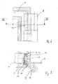
- Fig. 1 shows slightly schematically a wing 1 of a tilt-and-turn window, which is around a lower horizontal and one lateral vertical axis is pivotable. This is the Wing 1 at its upper horizontal wing leg with the frame 2 over a display device 3 connected.
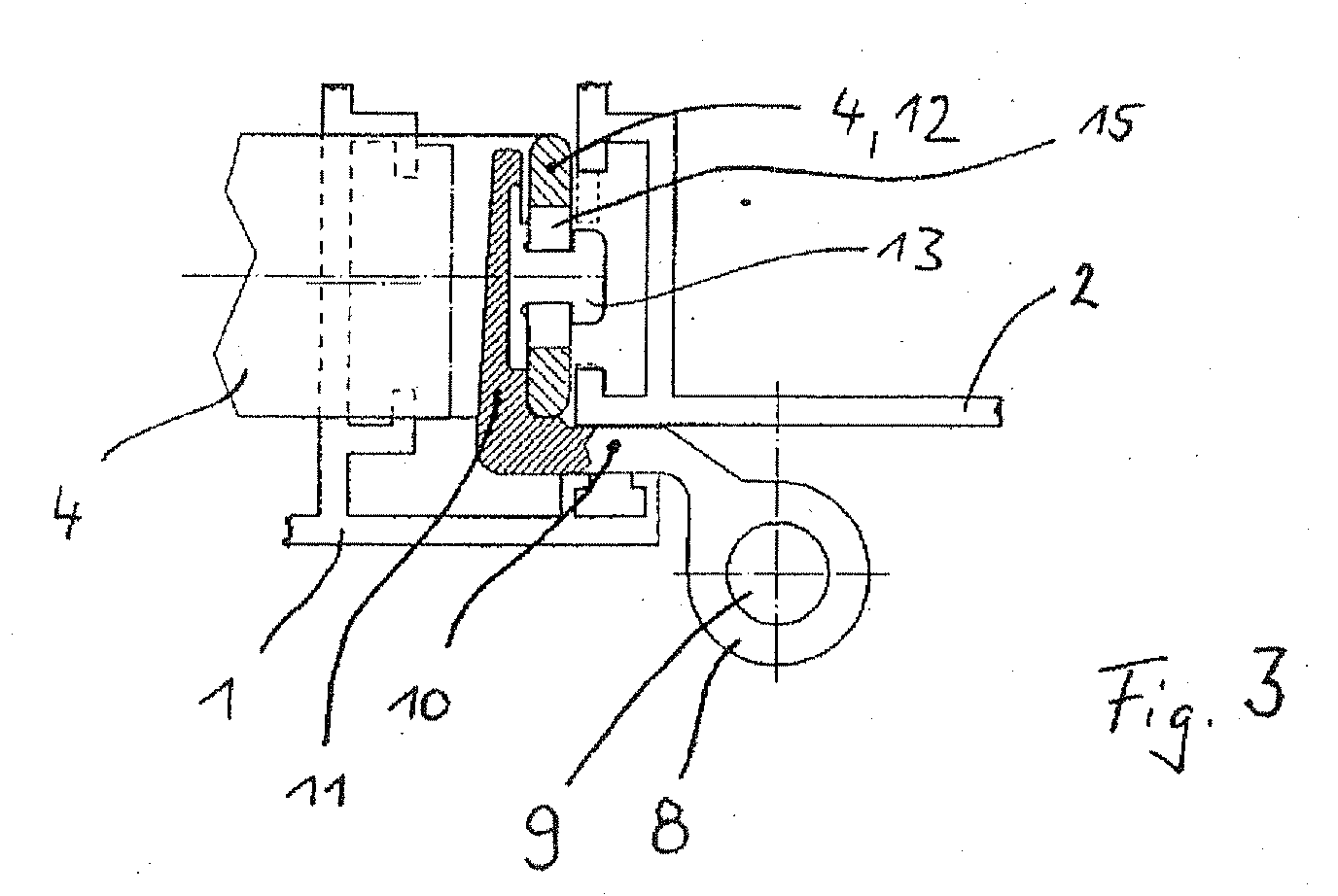
- the Ausstellvorraum 3 is with a Ausstellarm 4 provided pivoting at one end to the horizontal wing leg and is slidably mounted and the other end is associated with a pivot bearing 5.
- the pivot bearing 5 consists of a on the frame 2 to be fastened Bearing 6 and a wing part 7, with the bearing block 6 by means of a sleeve 8 of the wing portion 7 passing through hinge pin 9 is pivotally connected, such as a comparison with the Fig. 2 shows.
- the web 13 forms two positive locking elements (webs 13.1 and 13.2) by the web 13 is interrupted transversely to its axis of symmetry.
- the web 13.1 or 13.2 passes through in its illustrated functional position (FIG. 3) the leg 12 of the stay 4 in openings or recesses 14, 15, in 6 are recognizable.
- the recess 14 is as open edge slot formed while the recess 15 as a closed recess a Slot 16 with an extension 17 for the passage of one of the T-shaped webs 13.1 or 13.2 contains.
- the widened head of the web 13 (or the webs 13.1 and 13.2 engages behind the longitudinal edges of the recesses 14, 15 in the region of the narrower Sections.
- At least the recess 15 receives an L-shaped contour in which a leg on a longitudinal edge of the Schenkel 12 opens. This allows the bridge 13.1 or 13.2 with his foot in the Recess are introduced laterally on the leg and by moving longitudinally in its functional position be relocated. This embodiment reduces by the open-edged recess but the stability of the angled leg.
- the attachment of the wing part 7 on the leg 12 takes place in a known per se Way in that one of the webs-e.g. Bridge 13.1 in the extension 17 of Recess 15 is introduced, the dimensionally to the widened head of the Bridge 13 is adjusted.
- the portion lying between the recesses 14, 15 18 of the leg 12 is located between the webs 13.1 and 13.2, here a Have interruption 19.
- a longitudinal displacement of the web 13.1 is now in the narrow and matched to the foot of the web 13 slot 16 and the bridge 13.2 moved into the slot 14.
- the hinge flap 11 and the leg 12 in the direction 21 and opposite to each other fixed.
- the fuse element 22 consists of a Leaf spring 23, the middle acting between the two as positive locking elements Webs 13.1 and 13.2 in the region of the interruption 19 and the bore 20 is located.
- FIG. 5 Of particular advantage is the embodiment of FIG. 5, wherein the leaf spring 23 is added in sections in the bore 20 and at least partially an approximately circular and adapted to the bore 20 circumference 24 has.
- the leaf spring 23 is already at least in the longitudinal direction of the web 13 fixed and does not wear on the mounting tabs 11. Otherwise it would be namely necessary, between the fastening tab 12 and the leg 11th to provide a corresponding space. So can the manufacture of the 19 interruption used hole 20 at the same time to accommodate the Leaf spring 23 create necessary space.
- tuned perimeter 24 also allow a certain amount of commitment the leaf spring 23 transversely to the web 13 - in the direction 25 (Fig. 5), since due to the Making the interruption 19, the edge 26 in this direction a small Undercut forms.
- the undercut through the edge 26 may, for example, during assembly of the Leaf spring 23 are used on the pivot bearing 5 to a short-term Fixation bring about.
- it is more advantageous for alignment if the Leaf spring 23 has an angled web 27, which on the lateral edge 28th of the fastening tab 11 is present. As a result, the leaf spring 23 receives an opposite the direction 25 acting defined orientation relative to the fastening tabs 11th and at the same time within the bore 20 at right angles to Attachment tabs 11 aligned.
- the function of the leaf spring 23 is easily seen: During assembly of the wing part 7th on the leg 12, the portion 18 within the interruption 19 and the Bore 20 arranged, as already described above. Section 18 works doing so on the spring tongue 29, which thereby in the direction 21 in the flat bore 20th is pivoted into it. During subsequent displacement of the wing part 7 is the Section 18 relative to the wing part 7 so far displaced that this between the edge 30 of the spring tongue 29 and the web 13.1 and 13.2 is located. Jumps the spring tongue 29 Now back, so it lies between the spring tongue 29 and the web 13.1 and 13.2, so that a pushing back only with simultaneous deformation of the leaf spring 23rd is possible.
- This can be done, for example, by means of a wing 34 (FIG. 5), which is laterally next to the engaging in the bore 20 circular arc-shaped section lies.
- the Wing 34 terminates at an edge parallel to the pivot bearing axis edge, which comes to rest near the paragraph 33.
- the heel 33 may be partially sectioned e.g. be deformed by means of a forming die, so that the deformed material section 35 - as indicated in Figure 7 - the leaf spring 23 partially overlapped.
- the paragraph 33 clearly next to the widened head of the ridge 13 is located so that the paragraph 33 with the molding stamp light is reachable.
- a production of the wing part 7 is made a drawn profile easily possible, as for the production of the function exclusively a post-processing is necessary.
Landscapes
- Engineering & Computer Science (AREA)
- Mechanical Engineering (AREA)
- Hinges (AREA)
- Closing And Opening Devices For Wings, And Checks For Wings (AREA)
- Dental Tools And Instruments Or Auxiliary Dental Instruments (AREA)
Abstract
Gegenstand der Erfindung ist eine Ausstellvorrichtung für Fenster oder Türen mit mindestens einem Ausstellarm (4), der einerends am Flügel (1) schwenkbar und längsverschiebbar zu lagern und anderenends lösbar mit einem Schwenklager (5) kuppelbar ist. Das Schwenklager (5) besteht aus einem am Blendrahmen (2) zu befestigenden Lagerbock (6) und einem Flügelteil (7), das mit dem Lagerbock (6) mittels eines eine Hülse (8) des Flügelteils (7) durchsetzenden Gelenkbolzens (9) schwenkbar verbunden ist wobei sich an die Hülse (8) ein abgewinkelter Bandlappen (10) anschließt, dessen Befestigungslappen (11) zur Kopplung mit einem abgewinkelten Schenkel (12) des Ausstellarms (4) vorgesehen ist. Der Schenkel (12) ist mittels eines Sicherungselements (22) am Befestigungslappen (11) gehalten.The invention relates to a display device for windows or doors with at least one extension arm (4) which at one end on the wing (1) and pivotally longitudinally displaceable to store and at the other end detachable with a pivot bearing (5) is detachable. The pivot bearing (5) consists of a on the frame (2) fixing bearing block (6) and a wing part (7), which with the bearing block (6) by means of a hinge pin (9) passing through a sleeve (8) of the wing part (7) is pivotally connected to the sleeve (8) an angled hinge tab (10) connects, the fastening tabs (11) for coupling with a Angled leg (12) of the stay (4) is provided. The thigh (12) is held by a securing element (22) on the fastening tab (11).
Um eine möglichst einfache Verbindung des Ausstellarms (4) und des Bandlappens
(11) zu erreichen, welche eine einfache Herstellung der beteiligten Bauteile zulässt ist
vorgesehen, dass das Sicherungselement (22) aus einer Blattfeder (23) besteht, die
mittig zwischen zwei Formschlusselementen (13.1, 13.2) liegt, dass die
Formschlusselemente (13.1, 13.2) von einem unterbrochenen und im Querschnitt T-förmigen
Steg (13) des Befestigungslappens (11) gebildet werden, und dass die
Formschlusselemente (13.1, 13.2) in Öffnungen bzw. Ausnehmungen (14, 15) des
Schenkels (12) einführbar sind und diese hintergreifen.
Description
Gegenstand der Erfindung ist eine Ausstellvorrichtung nach dem Oberbegriff des
Anspruchs 1.The invention relates to a display device according to the preamble of
Aus der EP 0666 398 B1 ist eine Ausstellvorrichtung für ein Fenster oder eine Tür bekannt geworden, die einen Ausstellarm aufweist, der einerends am Flügel schwenkbar und längsverschiebbar zu lagern und anderenends lösbar mit einem Schwenklager kuppelbar ist. Das Schwenklager besteht aus einem am Blendrahmen zu befestigenden Lagerbock und einem Flügelteil, das mit dem Lagerbock mittels eines eine Hülse des Flügelteils durchsetzenden Gelenkbolzens schwenkbar verbunden ist. An die Hülse schließt sich ein abgewinkelter Bandlappen an, dessen Befestigungslappen zur Kopplung mit einem in Richtung der Schwenkachse abgewinkelten Schenkel des Ausstellarms vorgesehen ist. Dazu weist der Bandlappen eine Nut auf, in die der Schenkel des Ausstellarms eingeführt werden kann, so dass dieser in Längsrichtung des Ausstellarms formschlüssig aufgenommen ist. Um eine unerwünschtes entweichen aus der Verbindung zu erzielen ist, der Schenkel des Ausstellarms mit einer Blattfeder versehen, die so bemessen ist, dass sie den Befestigungslappen an einem Ende - im Bereich der Nut - hintergreift.From EP 0666 398 B1 is an opening device for a window or a door became known, which has a stay, the one at the wing to store pivotally and longitudinally displaceable and at the other end detachable with a Swing bearing is detachable. The pivot bearing consists of a on the frame to be fixed bearing block and a wing part, with the bearing block means a sleeve of the wing part passing through hinge pin pivotally connected is. The sleeve is followed by an angled hinge tab, whose Mounting tabs for coupling with a in the direction of the pivot axis Angled leg of the extension is provided. For this purpose, the hinge flap a groove into which the leg of the extension arm can be inserted so that this is received in a form-fitting manner in the longitudinal direction of the extension arm. To one To achieve undesirable escape from the joint is the thigh of the Arm provided with a leaf spring, which is dimensioned so that they Fixing tabs at one end - in the groove - engages behind.
Aus dem DE-GM 1 923 282 ist es ferner bekannt, einen Ausstellarm mit einem Scharnierteil über eine Renkverbindung miteinander zu verbinden. Der Ausstellarm weist dazu zwei im Abstand zueinander angeordnete Pilzzapfen auf, deren Lage abgestimmt ist mit zwei schlüssellochartigen Ausnehmungen an dem Scharnierteil. In die Erweiterungen der schlüssellochförmigen Ausnehmungen lassen sich die Pilzzapfen einführen, sodass die verbreiterten Köpfe nach einem Verschieben in die Funktionsstellung die Ränder des schmalen Abschnitts Ausnehmungen hintergreifen. Um auch hier ein unerwünschtes Verschieben aus der Funktionsstellung zu vermeiden ist eine Blattfeder vorgesehen, welche an dem Ausstellarm vorgesehen wird und welche bei der Montage des Scharnierteils zunächst durch dieses weggedrückt wird und nach dem Erreichen der Funktionsstellung eine Querkannte des Scharnierteils hintergreift, so dass eine Bewegung in entgegengesetzter Richtung zur Montagerichtung gesperrt ist. From DE-GM 1 923 282 it is also known, a stay with a Hinge part to connect with each other via a Renkverbindung. The extension arm has two spaced apart mushroom pin, their location is matched with two keyhole-like recesses on the hinge part. In the extensions of the keyhole-shaped recesses can be the Insert mushroom pins, so that the widened heads after moving into the Functional position engage behind the edges of the narrow section recesses. To here too an undesirable shift from the functional position to avoid a leaf spring is provided, which provided on the stay is and which in the assembly of the hinge part first by this is pushed away and after reaching the functional position a Querkannte of the hinge part engages behind, allowing a movement in the opposite direction is locked to the mounting direction.
Aufgabe der Erfindung ist es, eine möglichst einfache Verbindung des Ausstellarms und des Bandlappens zu erreichen, welche eine einfache Herstellung der beteiligten Bauteile zulässt.The object of the invention is to provide the simplest possible connection of the stay and Bandlappens to achieve, which is a simple production of the involved Allows components.
Die Lösung dieser Aufgabe gelingt mit den Merkmalen des Anspruchs 1. Es wird auf
diese Weise eine Herstellung des Bandlappens aus einem gezogenen Profilteil
möglich, welches nur einer geringen Nacharbeit zur Unterbrechung des Steges
bedarf. Der Ausstellarm ist nur mit einfach herzustellenden Ausnehmungen zu
versehen. Die Anordnung der Blattfeder an dem Befestigungslappen erleichtert die
Handhabung bei der Montage, da auf diese Weise nur das geringere Abmessungen
aufweisende Flügelteil bewegt werden muss. Die mittige Anordnung gewährleistet
dabei die Verwendung für nach links und nach rechts öffnenbare Flügel.The solution of this problem is achieved with the features of
Es ist ferner vorgesehen, dass der Steg mittels einer Bohrung durchbrochen wird. Dadurch wird in einem Arbeitsgang eine hinreichend große Unterbrechung des Steges, die darüber hinaus auch sehr einfach und maßhaltig ausgeführt werden kann.It is further provided that the web is broken by means of a bore. As a result, in a single operation a sufficiently large interruption of Bridge, which can also be made very simple and dimensionally stable.
Um eine Schwächung des Befestigungslappens zu vermeiden ist es von Vorteil, wenn die Bohrung als zylindrische Ausnehmung an dem Befestigungslappen ausgeführt ist. Dies kann beispielsweise mittels eines Schaftfräsers erreicht werden.In order to avoid weakening of the fastening tab, it is advantageous if the bore is designed as a cylindrical recess on the fastening tab. This can be achieved, for example, by means of an end mill.
Es kann auch vorgesehen werden, dass die Blattfeder abschnittsweise in der Bohrung aufgenommen ist und zumindest bereichsweise einen annähernd kreisförmigen und an die Bohrung angepassten Umfang hat. Dadurch ist die Blattfeder bereits in Längsrichtung des Steges festgelegt.It can also be provided that the leaf spring sections in the Bore is added and at least partially an approximate has circular and adapted to the bore circumference. This is the leaf spring already set in the longitudinal direction of the web.
Die Befestigung der Blattfeder kann noch dadurch verbessert werden, dass die Blattfeder einen abgewinkelten Steg aufweist, der an dem Befestigungslappen seitlich anliegt. Hierdurch ergibt sich eine Montageerleichterung, da die Blattfeder auch in dieser Richtung eine definierte Ausrichtung relativ zum Befestigungslappen erhält.The attachment of the leaf spring can be further improved by the Leaf spring has an angled web, which laterally on the mounting tab is applied. This results in a mounting relief, since the leaf spring in This direction receives a defined orientation relative to the mounting tab.
Zur unverlierbaren Befestigung der Blattfeder kann ferner vorgesehen werden, dass der Befestigungslappen einen parallel zur Schwenklagerachse verlaufenden Absatz aufweist, an dem die Blattfeder zumindest bereichsweise anliegt. Dieser Absatz kann abschnittsweise verformt werden, so dass der verformte Teil die Blattfeder teilweise überlappt. For captive attachment of the leaf spring can also be provided that the fastening tabs a parallel to the pivot bearing axis extending paragraph has, on which the leaf spring rests at least partially. This paragraph can be deformed in sections, so that the deformed part of the leaf spring partially overlaps.
Um die Stabilität des abgewinkelten Schenkel des Ausstellarms zu erhalten ist vorgesehen, dass der Befestigungslappen eine randoffene und eine geschlossene Ausnehmung enthält, wobei die randoffene Ausnehmung als Schlitz ausgebildet ist und die geschlossene Ausnehmung einen Schlitz mit einer Erweiterung zum Durchtritt eines der T-förmigen Stege enthält. Abweichend davon kann nämlich vorgesehen sein, dass zumindest eine der Ausnehmungen L-förmig und seitlich offen ist, so dass der Steg in die Ausnehmung seitlich am Schenkel eingeführt werden kann und durch längsverschieben in seine Funktionsstellung verlagert wird.In order to maintain the stability of the angled leg of the extension arm provided that the fastening tabs an open-edge and a closed Contains recess, wherein the open-edged recess is formed as a slot and the closed recess has a slot with an extension to the passage contains one of the T-shaped webs. By way of derogation, provision may be made be that at least one of the recesses is L-shaped and laterally open, so that the web can be inserted into the recess laterally on the leg and through is moved longitudinally displaced in its functional position.
Weitere vorteilhafte Ausgestaltungen ergeben sich aus den Fig. Es zeigt:
- Fig. 1
- ein Drehkippfenster mit einem gekippten Flügel,
- Fig. 2
- in einem größeren Maßstab den Lagerbock der Ausstellvorrichtung mit dem daran befestigten Ausstellarm,
- Fig. 3
- einen Schnitt entlang der Linie III-III in Fig. 2,
- Fig. 4
- einen Schnitt entlang der Linie IV-IV in Fig. 5 mit dem eingerasteten Sicherungselement,
- Fig. 5
- das Flügelteil mit dem Befestigungsteil in einer Draufsicht,
- Fig. 6
- den Schenkel des Ausstellarms und
- Fig. 7
- in einer vergrößerten Darstellung die Verbindung des Sicherungselementes mit dem Befestigungslappen.
- Fig. 1
- a tilt and turn window with a tilted wing,
- Fig. 2
- on a larger scale, the bearing block of the opening device with the stay arm attached thereto,
- Fig. 3
- a section along the line III-III in Fig. 2,
- Fig. 4
- a section along the line IV-IV in Figure 5 with the latched fuse element.
- Fig. 5
- the wing part with the fastening part in a plan view,
- Fig. 6
- the leg of the stay and
- Fig. 7
- in an enlarged view the connection of the securing element with the fastening tab.
Fig. 1 zeigt leicht schematisiert einen Flügel 1 eines Drehkipp-Fensters, der um eine
untere horizontale und eine seitliche vertikale Achse schwenkbar ist. Dazu ist der
Flügel 1 an seinem oberen horizontalen Flügelschenkel mit dem Blendrahmen 2 über
eine Ausstellvorrichtung 3 verbunden. Die Ausstellvorrichtung 3 ist mit einem
Ausstellarm 4 versehen, der einenends an dem horizontalen Flügelschenkel schwenk-
und verschiebbar gelagert ist und anderenends einem Schwenklager 5 zugeordnet ist.Fig. 1 shows slightly schematically a
Das Schwenklager 5 besteht aus einem am Blendrahmen 2 zu befestigenden
Lagerbock 6 und einem Flügelteil 7, das mit dem Lagerbock 6 mittels eines eine Hülse
8 des Flügelteils 7 durchsetzenden Gelenkbolzens 9 schwenkbar verbunden ist, wie
ein Vergleich mit der Fig. 2 zeigt. Wie auch in Verbindung mit der Fig. 3 ersichtlich,
schließt sich an die Hülse 8 ein abgewinkelter Bandlappen 10 an, dessen
Befestigungslappen 11 zur Kopplung mit einem abgewinkelten Schenkel 12 des
Ausstellarms 4 dient. The pivot bearing 5 consists of a on the
Es kann aber abweichend von der Darstellung nach Fig. 2 und 3 auch vorgesehen
werden, dass anstelle der einteiligen Ausgestaltung des Ausstellarms 4 ein
Winkelstück vorgesehen wird, welches mit einem Schenkels an dem Ausstellarm 4
angeschlossen ist und mit dem anderen Schenkel den Schenkel 12 bildet.However, it may deviate from the representation of FIG. 2 and 3 also provided
be that instead of the one-piece design of the stay 4 a
Elbow is provided, which with a leg on the
In den Fig. 3 und 4 ist die Verbindung des Schenkels 12 des Ausstellarms 4 und des
Befestigungslappens 11 erkennbar. Der Befestigungslappen 11 ist auf seiner dem
Schenkel 12 zugeordneten Fläche mit einen im wesentlichen T-förmigen Steg 13
versehen.In Figs. 3 and 4, the connection of the
Ausweislich der Fign. 3 bis 6 bildet der Steg 13 zwei Formschlusselemente (Stege
13.1 und 13.2), indem der Steg 13 quer zu seiner Symmetrieachse unterbrochen wird.
Der Steg 13.1 bzw. 13.2 durchgreift in seiner dargestellten Funktionsstellung (Fig. 3)
den Schenkel 12 des Ausstellarms 4 in Öffnungen oder Ausnehmungen 14, 15, die in
der Fig. 6 erkennbar sind. Die Ausnehmung 14 ist dabei als randoffener Schlitz
ausgebildet, während die Ausnehmung 15 als geschlossene Ausnehmung einen
Schlitz 16 mit einer Erweiterung 17 zum Durchtritt eines der T-förmigen Stege 13.1
bzw. 13.2 enthält. Der verbreiterte Kopf des Stegs 13 (bzw. der Stege 13.1 und 13.2
hintergreift dabei die Längsränder der Ausnehmungen 14, 15 im Bereich der engeren
Abschnitte.Evidenced the Fign. 3 to 6, the
Abweichend davon kann nämlich vorgesehen sein, dass zumindest die Ausnehmung
15 eine L-förmige Kontur erhält, bei der ein Schenkel an einer Längskante des
Schenkels 12 mündet. Dadurch kann der Steg 13.1 oder 13.2 mit seinem Fuß in die
Ausnehmung seitlich am Schenkel eingeführt werden und durch längsverschieben in
seine Funktionsstellung verlagert werden. Diese Ausgestaltung mindert durch die
randoffene Ausnehmung jedoch die Stabilität des abgewinkelten Schenkels.By way of derogation, it may be provided that at least the
Die Befestigung des Flügelteils 7 an dem Schenkel 12 erfolgt in an sich bekannter
Weise dadurch, dass einer der Stege -z.B. Steg 13.1 in die Erweiterung 17 der
Ausnehmung 15 eingeführt wird, die dazu maßlich an den verbreiterten Kopf des
Stegs 13 angepasst ist. Der zwischen den Ausnehmungen 14, 15 liegende Abschnitt
18 des Schenkels 12 liegt dazu zwischen den Stegen 13.1 und 13.2, die hier eine
Unterbrechung 19 aufweisen. Durch ein Längsverschieben wird der Steg 13.1 nun in
den schmalen und auf den Fuß des Steges 13 abgestimmten Schlitz 16 und der Steg
13.2 in den Schlitz 14 verschoben. Dadurch ist der Bandlappen 11 und der Schenkel
12 in Richtung 21 und entgegengesetzt dazu aneinander festgelegt.The attachment of the wing part 7 on the
Durch die Unterbrechung 19 werden die Stege 13.1 und 13.2 aus dem Steg 13
gebildet, wie aus der Fig. 5 ersichtlich. Wie hier auch erkennbar ist vorgesehen, dass
der Steg 13 mittels einer Bohrung 20 durchbrochen wird. Dadurch wird in einem
Arbeitsgang eine hinreichend große Unterbrechung 19 des Steges 13 auf einfache
Weise bewirkt, die darüber hinaus auch sehr einfach und maßhaltig ausgeführt
werden kann. In Verbindung mit der Fig. 4 wird deutlich, dass die Bohrung 20 als
flache zylindrische Ausnehmung an dem Befestigungslappen 11 ausgeführt ist. Dies
vermeidet eine Schwächung des Befestigungslappens 11 und die Bohrung 20 kann
als flache Sacklochbohrung beispielsweise mittels eines Schaftfräsers hergestellt
werden.Due to the
Um ein Lösen der Verbindung von Befestigungslappen und Schenkel 12 zu
verhindern ist vorgesehen, dass der Schenkel 12 mittels eines Sicherungselements 22
am Befestigungslappen 11 gehalten ist. Das Sicherungselement 22 besteht aus einer
Blattfeder 23, die mittig zwischen den zwei als Formschlusselementen wirksamen
Stegen 13.1 und 13.2 im Bereich der Unterbrechung 19 bzw. der Bohrung 20 liegt.To loosen the connection of fastening tabs and
Von besonderem Vorteil ist dabei die Ausgestaltung nach Fig. 5, bei der die Blattfeder
23 abschnittsweise in der Bohrung 20 aufgenommen ist und zumindest bereichsweise
einen annähernd kreisförmigen und an die Bohrung 20 angepassten Umfang 24 hat.
Dadurch ist die Blattfeder 23 nämlich bereits zumindest in Längsrichtung des Steges
13 festgelegt und trägt nicht auf den Befestigungslappen 11 auf. Anderenfalls wäre es
nämlich notwendig, zwischen dem Befestigungslappen 12 und dem Schenkel 11
einen entsprechenden Freiraum vorzusehen. So kann die zur Herstellung der
Unterbrechung 19 verwendete Bohrung 20 gleichzeitig den zur Unterbringung der
Blattfeder 23 notwendigen Raum schaffen. Die Bohrung 20 und der darauf
abgestimmte Umfang 24 erlauben aber darüber hinaus auch eine gewisse Festlegung
der Blattfeder 23 quer zu dem Steg 13 - in Richtung 25 (Fig. 5), da bedingt durch die
Herstellung der Unterbrechung 19 die Kante 26 in dieser Richtung einen geringen
Hinterschnitt bildet.Of particular advantage is the embodiment of FIG. 5, wherein the
Der Hinterschnitt durch die Kante 26 kann beispielsweise bei der Montage der
Blattfeder 23 an dem Schwenklager 5 verwendet werden, um eine kurzzeitige
Fixierung herbei zu führen. Vorteilhafter für eine Ausrichtung ist es jedoch, wenn die
Blattfeder 23 einen abgewinkelten Steg 27 aufweist, der an dem seitlichen Rand 28
des Befestigungslappens 11 anliegt. Hierdurch erhält die Blattfeder 23 eine entgegen
der Richtung 25 wirkende definierte Ausrichtung relativ zum Befestigungslappen 11
und wird gleichzeitig auch innerhalb der Bohrung 20 rechtwinklig zum
Befestigungslappen 11 ausgerichtet.The undercut through the
Die Funktion der Blattfeder 23 ist leicht ersichtlich: Bei der Montage des Flügelteils 7
an dem Schenkel 12 wird der Abschnitt 18 innerhalb der Unterbrechung 19 bzw. der
Bohrung 20 angeordnet, wie vorstehend bereits beschrieben. Der Abschnitt 18 wirkt
dabei auf die Federzunge 29, die dadurch in Richtung 21 in die flache Bohrung 20
hinein verschwenkt wird. Beim anschließenden Verschieben des Flügelteils 7 wird der
Abschnitt 18 relativ zum Flügelteil 7 so weit verlagert, dass dieser zwischen dem Rand
30 der Federzunge 29 und dem Steg 13.1 bzw. 13.2 liegt. Springt die Federzunge 29
nun zurück, so liegt sie zwischen der Federzunge 29 und dem Steg 13.1 bzw. 13.2, so
dass ein Zurückschieben nur unter gleichzeitiger Verformung der Blattfeder 23
möglich ist.The function of the
Es ist leicht ersichtlich, dass dazu der lichte Abstand der Federzunge 29 und des
Steges 13.1 oder 13.2 etwas größer bemessen sein muss als die Länge (entlang der
Mittelachse 32) des Anschnitts 18. Es ist aus der Fig. 4 und auch der Fig. 7
erkennbar, dass die Federzunge 29 so gebogen ist, dass sie in den Bereich des
Schenkels 12 vorragt.It is easy to see that the clearance of the
Zur unverlierbaren Befestigung der Blattfeder deutlich. Hierzu ist vorgesehen, dass
der Befestigungslappen 11 einen parallel zur Schwenklagerachse, also der Hülse 8,
verlaufenden Absatz 33 aufweist, an dem die Blattfeder 23 zumindest bereichsweise
anliegt. Dies kann beispielsweise mittels eines Flügels 34 (Fig. 5) erfolgen, der seitlich
neben dem in die Bohrung 20 eingreifenden kreisbogenförmigen Abschnitt liegt. Der
Flügel 34 endet an einer zur Schwenklagerachse parallelverlaufenden Kante, welche
nahe dem Absatz 33 zu liegen kommt. Der Absatz 33 kann abschnittsweise z.B.
mittels eines Formstempels verformt werden, so dass der verformte Materialabschnitt
35 - wie in Fig 7 angedeutet - die Blattfeder 23 teilweise überlappt. For captive attachment of the leaf spring clearly. For this purpose, it is provided that
the fastening tabs 11 a parallel to the pivot bearing axis, ie the sleeve 8,
extending
Für diese Ausgestaltung ist es zweckmäßig, dass der Absatz 33 deutlich neben dem
verbreiterten Kopf des Stegs 13 liegt, damit der Absatz 33 mit dem Formstempel leicht
erreichbar ist.For this embodiment, it is expedient that the
Durch die beschriebene Ausgestaltung ist eine Herstellung des Flügelteils 7 aus einem gezogenen Profil leicht möglich, da zur Herstellung der Funktion ausschließlich eine Nachbearbeitung notwendig ist. Due to the described embodiment, a production of the wing part 7 is made a drawn profile easily possible, as for the production of the function exclusively a post-processing is necessary.
- 11
- Flügelwing
- 22
- Rahmenframe
- 33
- AusstellvorrichtungA stay mechanism
- 44
- Ausstellarmout arm
- 55
- Schwenklagerpivot bearing
- 66
- Lagerbockbearing block
- 77
- Flügelteilwing part
- 88th
- Hülseshell
- 99
- Gelenkbolzenhinge pins
- 1010
- Bandlappenhinge flap
- 1111
- Befestigungslappenfastening tabs
- 1212
- Schenkelleg
- 1313
- Stegweb
- 13.113.1
- Stegweb
- 13.213.2
- Stegweb
- 1414
- Ausnehmungrecess
- 1515
- Ausnehmungrecess
- 1616
- Schlitzslot
- 1717
- Erweiterungextension
- 1818
- Abschnittsection
- 1919
- Unterbrechunginterruption
- 2020
- Bohrungdrilling
- 2121
- Richtungdirection
- 2222
- Sicherungselementfuse element
- 2323
- Blattfederleaf spring
- 2424
- Umfangscope
- 2525
- Richtungdirection
- 2626
- Kanteedge
- 2727
- Stegweb
- 2828
- Randedge
- 2929
- Federzungespring tongue
- 3030
- Randedge
- 3232
- Mittelachsecentral axis
- 3333
- Absatzparagraph
- 3434
- Flügelwing
- 3535
- Materialabschnittmaterial section
Claims (7)
Applications Claiming Priority (2)
| Application Number | Priority Date | Filing Date | Title |
|---|---|---|---|
| DE202004004927U | 2004-03-26 | ||
| DE202004004927U DE202004004927U1 (en) | 2004-03-26 | 2004-03-26 | A stay mechanism |
Publications (3)
| Publication Number | Publication Date |
|---|---|
| EP1580379A2 true EP1580379A2 (en) | 2005-09-28 |
| EP1580379A3 EP1580379A3 (en) | 2009-07-15 |
| EP1580379B1 EP1580379B1 (en) | 2010-06-02 |
Family
ID=34854235
Family Applications (1)
| Application Number | Title | Priority Date | Filing Date |
|---|---|---|---|
| EP05100856A Expired - Lifetime EP1580379B1 (en) | 2004-03-26 | 2005-02-08 | Fitting arrangement for tiltable wings of windows, doors or the like |
Country Status (4)
| Country | Link |
|---|---|
| EP (1) | EP1580379B1 (en) |
| AT (1) | ATE470039T1 (en) |
| DE (2) | DE202004004927U1 (en) |
| ES (1) | ES2343416T3 (en) |
Family Cites Families (3)
| Publication number | Priority date | Publication date | Assignee | Title |
|---|---|---|---|---|
| DE1923282U (en) * | 1965-06-30 | 1965-09-09 | Hans Bilstein | EXTENSION BAR FOR TILT-TURNING WINDOWS OD. DGL. |
| DE4040233C2 (en) * | 1990-12-15 | 1994-11-03 | Bilstein August Gmbh Co Kg | Swivel bearing on an opening device of turn-tilt sashes of windows, doors or the like |
| DE9401699U1 (en) * | 1994-02-02 | 1994-03-17 | Roto Frank Ag, 70771 Leinfelden-Echterdingen | Display device for windows, doors or the like. |
-
2004
- 2004-03-26 DE DE202004004927U patent/DE202004004927U1/en not_active Expired - Lifetime
-
2005
- 2005-02-08 DE DE502005009662T patent/DE502005009662D1/en not_active Expired - Lifetime
- 2005-02-08 ES ES05100856T patent/ES2343416T3/en not_active Expired - Lifetime
- 2005-02-08 EP EP05100856A patent/EP1580379B1/en not_active Expired - Lifetime
- 2005-02-08 AT AT05100856T patent/ATE470039T1/en active
Also Published As
| Publication number | Publication date |
|---|---|
| DE502005009662D1 (en) | 2010-07-15 |
| EP1580379A3 (en) | 2009-07-15 |
| ATE470039T1 (en) | 2010-06-15 |
| EP1580379B1 (en) | 2010-06-02 |
| DE202004004927U1 (en) | 2005-08-11 |
| ES2343416T3 (en) | 2010-07-30 |
Similar Documents
| Publication | Publication Date | Title |
|---|---|---|
| EP4180601B1 (en) | Door hinge with elongated slide | |
| EP1072745A1 (en) | Lock fitting for windows or doors | |
| WO1990015911A1 (en) | Hinge | |
| EP1308590A1 (en) | Edge bolt for a door | |
| DE8526659U1 (en) | Sash for a window, a door or the like. | |
| EP0249682A2 (en) | Checking device for the wings of windows, doors or the like, provided with a security device against closing in the open position of the wings | |
| DE10050796C1 (en) | Pivot hinge, for door or window, has one hinge part provided by rotary strap adjusted in horizontal plane via setting and locking device | |
| EP1580379B1 (en) | Fitting arrangement for tiltable wings of windows, doors or the like | |
| DE19758907B4 (en) | A flap having a flap of a window, a door or the like, with a hinge fitting and mounting method of the hinge fitting | |
| EP0246431A2 (en) | Checking device for a tilting wing, especially for a tilting and pivoting wing, or sliding and tilting wing of windows, doors or the like | |
| EP1759081B1 (en) | Outward positioning device | |
| EP3034727B1 (en) | Safe-t-catch lock with a safe-t-catch | |
| DE20012351U1 (en) | Window or door with relief device | |
| EP2811093B1 (en) | Support member of a pivoting fitting which can be fixed to a cover frame of a door or window | |
| DE9301655U1 (en) | Hinge fitting | |
| DE60115160T2 (en) | Intermediate fitting for door or window for invisible hinge fitting | |
| EP2374973B1 (en) | Belt for doors, windows and similar | |
| DE7112124U (en) | Opening device for tilting swivel sashes of windows, doors or | |
| WO2007087945A1 (en) | Hinge assembly for the articulated connection of a door leaf, a window casement or similar to a frame | |
| DE602004006501T2 (en) | Telescopic window brace | |
| AT379648B (en) | DOOR FITTING | |
| EP3205803B1 (en) | Device for damping and limiting an opening movement | |
| CH562386A5 (en) | ||
| DE2551316A1 (en) | Two side window stay mechanism - has adjusting element in hinge arm acting on lug protruding from stay arm end | |
| DE10306378A1 (en) | Bolt locking system for window or door has coupling element movable with respect to swing arm and movable catch can engage in slot in swing arm |
Legal Events
| Date | Code | Title | Description |
|---|---|---|---|
| PUAI | Public reference made under article 153(3) epc to a published international application that has entered the european phase |
Free format text: ORIGINAL CODE: 0009012 |
|
| AK | Designated contracting states |
Kind code of ref document: A2 Designated state(s): AT BE BG CH CY CZ DE DK EE ES FI FR GB GR HU IE IS IT LI LT LU MC NL PL PT RO SE SI SK TR |
|
| AX | Request for extension of the european patent |
Extension state: AL BA HR LV MK YU |
|
| PUAL | Search report despatched |
Free format text: ORIGINAL CODE: 0009013 |
|
| AK | Designated contracting states |
Kind code of ref document: A3 Designated state(s): AT BE BG CH CY CZ DE DK EE ES FI FR GB GR HU IE IS IT LI LT LU MC NL PL PT RO SE SI SK TR |
|
| AX | Request for extension of the european patent |
Extension state: AL BA HR LV MK YU |
|
| 17P | Request for examination filed |
Effective date: 20090819 |
|
| GRAP | Despatch of communication of intention to grant a patent |
Free format text: ORIGINAL CODE: EPIDOSNIGR1 |
|
| AKX | Designation fees paid |
Designated state(s): AT BE BG CH CY CZ DE DK EE ES FI FR GB GR HU IE IS IT LI LT LU MC NL PL PT RO SE SI SK TR |
|
| GRAF | Information related to payment of grant fee modified |
Free format text: ORIGINAL CODE: EPIDOSCIGR3 |
|
| GRAS | Grant fee paid |
Free format text: ORIGINAL CODE: EPIDOSNIGR3 |
|
| GRAA | (expected) grant |
Free format text: ORIGINAL CODE: 0009210 |
|
| AK | Designated contracting states |
Kind code of ref document: B1 Designated state(s): AT BE BG CH CY CZ DE DK EE ES FI FR GB GR HU IE IS IT LI LT LU MC NL PL PT RO SE SI SK TR |
|
| REG | Reference to a national code |
Ref country code: GB Ref legal event code: FG4D Free format text: NOT ENGLISH |
|
| REG | Reference to a national code |
Ref country code: CH Ref legal event code: EP |
|
| REG | Reference to a national code |
Ref country code: IE Ref legal event code: FG4D Free format text: LANGUAGE OF EP DOCUMENT: GERMAN |
|
| REF | Corresponds to: |
Ref document number: 502005009662 Country of ref document: DE Date of ref document: 20100715 Kind code of ref document: P |
|
| REG | Reference to a national code |
Ref country code: ES Ref legal event code: FG2A Ref document number: 2343416 Country of ref document: ES Kind code of ref document: T3 |
|
| REG | Reference to a national code |
Ref country code: NL Ref legal event code: VDEP Effective date: 20100602 |
|
| PG25 | Lapsed in a contracting state [announced via postgrant information from national office to epo] |
Ref country code: LT Free format text: LAPSE BECAUSE OF FAILURE TO SUBMIT A TRANSLATION OF THE DESCRIPTION OR TO PAY THE FEE WITHIN THE PRESCRIBED TIME-LIMIT Effective date: 20100602 Ref country code: SE Free format text: LAPSE BECAUSE OF FAILURE TO SUBMIT A TRANSLATION OF THE DESCRIPTION OR TO PAY THE FEE WITHIN THE PRESCRIBED TIME-LIMIT Effective date: 20100602 |
|
| LTIE | Lt: invalidation of european patent or patent extension |
Effective date: 20100602 |
|
| PG25 | Lapsed in a contracting state [announced via postgrant information from national office to epo] |
Ref country code: FI Free format text: LAPSE BECAUSE OF FAILURE TO SUBMIT A TRANSLATION OF THE DESCRIPTION OR TO PAY THE FEE WITHIN THE PRESCRIBED TIME-LIMIT Effective date: 20100602 Ref country code: SI Free format text: LAPSE BECAUSE OF FAILURE TO SUBMIT A TRANSLATION OF THE DESCRIPTION OR TO PAY THE FEE WITHIN THE PRESCRIBED TIME-LIMIT Effective date: 20100602 |
|
| PG25 | Lapsed in a contracting state [announced via postgrant information from national office to epo] |
Ref country code: CY Free format text: LAPSE BECAUSE OF FAILURE TO SUBMIT A TRANSLATION OF THE DESCRIPTION OR TO PAY THE FEE WITHIN THE PRESCRIBED TIME-LIMIT Effective date: 20100602 Ref country code: PL Free format text: LAPSE BECAUSE OF FAILURE TO SUBMIT A TRANSLATION OF THE DESCRIPTION OR TO PAY THE FEE WITHIN THE PRESCRIBED TIME-LIMIT Effective date: 20100602 |
|
| REG | Reference to a national code |
Ref country code: IE Ref legal event code: FD4D |
|
| PG25 | Lapsed in a contracting state [announced via postgrant information from national office to epo] |
Ref country code: IE Free format text: LAPSE BECAUSE OF FAILURE TO SUBMIT A TRANSLATION OF THE DESCRIPTION OR TO PAY THE FEE WITHIN THE PRESCRIBED TIME-LIMIT Effective date: 20100602 Ref country code: NL Free format text: LAPSE BECAUSE OF FAILURE TO SUBMIT A TRANSLATION OF THE DESCRIPTION OR TO PAY THE FEE WITHIN THE PRESCRIBED TIME-LIMIT Effective date: 20100602 Ref country code: EE Free format text: LAPSE BECAUSE OF FAILURE TO SUBMIT A TRANSLATION OF THE DESCRIPTION OR TO PAY THE FEE WITHIN THE PRESCRIBED TIME-LIMIT Effective date: 20100602 |
|
| PG25 | Lapsed in a contracting state [announced via postgrant information from national office to epo] |
Ref country code: IS Free format text: LAPSE BECAUSE OF FAILURE TO SUBMIT A TRANSLATION OF THE DESCRIPTION OR TO PAY THE FEE WITHIN THE PRESCRIBED TIME-LIMIT Effective date: 20101002 Ref country code: SK Free format text: LAPSE BECAUSE OF FAILURE TO SUBMIT A TRANSLATION OF THE DESCRIPTION OR TO PAY THE FEE WITHIN THE PRESCRIBED TIME-LIMIT Effective date: 20100602 Ref country code: RO Free format text: LAPSE BECAUSE OF FAILURE TO SUBMIT A TRANSLATION OF THE DESCRIPTION OR TO PAY THE FEE WITHIN THE PRESCRIBED TIME-LIMIT Effective date: 20100602 Ref country code: CZ Free format text: LAPSE BECAUSE OF FAILURE TO SUBMIT A TRANSLATION OF THE DESCRIPTION OR TO PAY THE FEE WITHIN THE PRESCRIBED TIME-LIMIT Effective date: 20100602 Ref country code: PT Free format text: LAPSE BECAUSE OF FAILURE TO SUBMIT A TRANSLATION OF THE DESCRIPTION OR TO PAY THE FEE WITHIN THE PRESCRIBED TIME-LIMIT Effective date: 20101004 |
|
| PLBE | No opposition filed within time limit |
Free format text: ORIGINAL CODE: 0009261 |
|
| STAA | Information on the status of an ep patent application or granted ep patent |
Free format text: STATUS: NO OPPOSITION FILED WITHIN TIME LIMIT |
|
| PG25 | Lapsed in a contracting state [announced via postgrant information from national office to epo] |
Ref country code: DK Free format text: LAPSE BECAUSE OF FAILURE TO SUBMIT A TRANSLATION OF THE DESCRIPTION OR TO PAY THE FEE WITHIN THE PRESCRIBED TIME-LIMIT Effective date: 20100602 |
|
| 26N | No opposition filed |
Effective date: 20110303 |
|
| REG | Reference to a national code |
Ref country code: DE Ref legal event code: R097 Ref document number: 502005009662 Country of ref document: DE Effective date: 20110302 |
|
| PG25 | Lapsed in a contracting state [announced via postgrant information from national office to epo] |
Ref country code: MC Free format text: LAPSE BECAUSE OF NON-PAYMENT OF DUE FEES Effective date: 20110228 |
|
| REG | Reference to a national code |
Ref country code: CH Ref legal event code: PL |
|
| GBPC | Gb: european patent ceased through non-payment of renewal fee |
Effective date: 20110208 |
|
| PG25 | Lapsed in a contracting state [announced via postgrant information from national office to epo] |
Ref country code: CH Free format text: LAPSE BECAUSE OF NON-PAYMENT OF DUE FEES Effective date: 20110228 Ref country code: LI Free format text: LAPSE BECAUSE OF NON-PAYMENT OF DUE FEES Effective date: 20110228 |
|
| PG25 | Lapsed in a contracting state [announced via postgrant information from national office to epo] |
Ref country code: GB Free format text: LAPSE BECAUSE OF NON-PAYMENT OF DUE FEES Effective date: 20110208 |
|
| REG | Reference to a national code |
Ref country code: AT Ref legal event code: MM01 Ref document number: 470039 Country of ref document: AT Kind code of ref document: T Effective date: 20110208 |
|
| PG25 | Lapsed in a contracting state [announced via postgrant information from national office to epo] |
Ref country code: AT Free format text: LAPSE BECAUSE OF NON-PAYMENT OF DUE FEES Effective date: 20110208 |
|
| PG25 | Lapsed in a contracting state [announced via postgrant information from national office to epo] |
Ref country code: LU Free format text: LAPSE BECAUSE OF NON-PAYMENT OF DUE FEES Effective date: 20110208 |
|
| PG25 | Lapsed in a contracting state [announced via postgrant information from national office to epo] |
Ref country code: BG Free format text: LAPSE BECAUSE OF FAILURE TO SUBMIT A TRANSLATION OF THE DESCRIPTION OR TO PAY THE FEE WITHIN THE PRESCRIBED TIME-LIMIT Effective date: 20100902 Ref country code: TR Free format text: LAPSE BECAUSE OF FAILURE TO SUBMIT A TRANSLATION OF THE DESCRIPTION OR TO PAY THE FEE WITHIN THE PRESCRIBED TIME-LIMIT Effective date: 20100602 |
|
| PG25 | Lapsed in a contracting state [announced via postgrant information from national office to epo] |
Ref country code: HU Free format text: LAPSE BECAUSE OF FAILURE TO SUBMIT A TRANSLATION OF THE DESCRIPTION OR TO PAY THE FEE WITHIN THE PRESCRIBED TIME-LIMIT Effective date: 20100602 |
|
| PG25 | Lapsed in a contracting state [announced via postgrant information from national office to epo] |
Ref country code: GR Free format text: LAPSE BECAUSE OF FAILURE TO SUBMIT A TRANSLATION OF THE DESCRIPTION OR TO PAY THE FEE WITHIN THE PRESCRIBED TIME-LIMIT Effective date: 20100602 |
|
| REG | Reference to a national code |
Ref country code: FR Ref legal event code: PLFP Year of fee payment: 12 |
|
| REG | Reference to a national code |
Ref country code: FR Ref legal event code: PLFP Year of fee payment: 13 |
|
| REG | Reference to a national code |
Ref country code: FR Ref legal event code: PLFP Year of fee payment: 14 |
|
| PGFP | Annual fee paid to national office [announced via postgrant information from national office to epo] |
Ref country code: DE Payment date: 20220221 Year of fee payment: 18 |
|
| PGFP | Annual fee paid to national office [announced via postgrant information from national office to epo] |
Ref country code: IT Payment date: 20220228 Year of fee payment: 18 Ref country code: FR Payment date: 20220219 Year of fee payment: 18 Ref country code: ES Payment date: 20220301 Year of fee payment: 18 Ref country code: BE Payment date: 20220218 Year of fee payment: 18 |
|
| REG | Reference to a national code |
Ref country code: DE Ref legal event code: R119 Ref document number: 502005009662 Country of ref document: DE |
|
| REG | Reference to a national code |
Ref country code: BE Ref legal event code: MM Effective date: 20230228 |
|
| PG25 | Lapsed in a contracting state [announced via postgrant information from national office to epo] |
Ref country code: IT Free format text: LAPSE BECAUSE OF NON-PAYMENT OF DUE FEES Effective date: 20230208 Ref country code: FR Free format text: LAPSE BECAUSE OF NON-PAYMENT OF DUE FEES Effective date: 20230228 Ref country code: DE Free format text: LAPSE BECAUSE OF NON-PAYMENT OF DUE FEES Effective date: 20230901 |
|
| PG25 | Lapsed in a contracting state [announced via postgrant information from national office to epo] |
Ref country code: BE Free format text: LAPSE BECAUSE OF NON-PAYMENT OF DUE FEES Effective date: 20230228 |
|
| REG | Reference to a national code |
Ref country code: ES Ref legal event code: FD2A Effective date: 20240402 |
|
| PG25 | Lapsed in a contracting state [announced via postgrant information from national office to epo] |
Ref country code: ES Free format text: LAPSE BECAUSE OF NON-PAYMENT OF DUE FEES Effective date: 20230209 |
|
| PG25 | Lapsed in a contracting state [announced via postgrant information from national office to epo] |
Ref country code: ES Free format text: LAPSE BECAUSE OF NON-PAYMENT OF DUE FEES Effective date: 20230209 |