EP1580379B1 - Ausstellvorrichtung für die Flügel von Fenstern, Türen od. dgl - Google Patents
Ausstellvorrichtung für die Flügel von Fenstern, Türen od. dgl Download PDFInfo
- Publication number
- EP1580379B1 EP1580379B1 EP05100856A EP05100856A EP1580379B1 EP 1580379 B1 EP1580379 B1 EP 1580379B1 EP 05100856 A EP05100856 A EP 05100856A EP 05100856 A EP05100856 A EP 05100856A EP 1580379 B1 EP1580379 B1 EP 1580379B1
- Authority
- EP
- European Patent Office
- Prior art keywords
- leaf spring
- check device
- web
- recess
- fastening plate
- Prior art date
- Legal status (The legal status is an assumption and is not a legal conclusion. Google has not performed a legal analysis and makes no representation as to the accuracy of the status listed.)
- Expired - Lifetime
Links
- 238000006073 displacement reaction Methods 0.000 claims description 6
- 230000008878 coupling Effects 0.000 claims description 3
- 238000010168 coupling process Methods 0.000 claims description 3
- 238000005859 coupling reaction Methods 0.000 claims description 3
- 230000000717 retained effect Effects 0.000 claims 1
- 235000001674 Agaricus brunnescens Nutrition 0.000 description 2
- 230000003313 weakening effect Effects 0.000 description 2
- 238000005553 drilling Methods 0.000 description 1
- 230000014759 maintenance of location Effects 0.000 description 1
Images


Classifications
-
- E—FIXED CONSTRUCTIONS
- E05—LOCKS; KEYS; WINDOW OR DOOR FITTINGS; SAFES
- E05D—HINGES OR SUSPENSION DEVICES FOR DOORS, WINDOWS OR WINGS
- E05D15/00—Suspension arrangements for wings
- E05D15/48—Suspension arrangements for wings allowing alternative movements
- E05D15/52—Suspension arrangements for wings allowing alternative movements for opening about a vertical as well as a horizontal axis
- E05D15/5205—Suspension arrangements for wings allowing alternative movements for opening about a vertical as well as a horizontal axis with horizontally-extending checks
-
- E—FIXED CONSTRUCTIONS
- E05—LOCKS; KEYS; WINDOW OR DOOR FITTINGS; SAFES
- E05D—HINGES OR SUSPENSION DEVICES FOR DOORS, WINDOWS OR WINGS
- E05D7/00—Hinges or pivots of special construction
- E05D7/02—Hinges or pivots of special construction for use on the right-hand as well as the left-hand side; Convertible right-hand or left-hand hinges
-
- E—FIXED CONSTRUCTIONS
- E05—LOCKS; KEYS; WINDOW OR DOOR FITTINGS; SAFES
- E05Y—INDEXING SCHEME ASSOCIATED WITH SUBCLASSES E05D AND E05F, RELATING TO CONSTRUCTION ELEMENTS, ELECTRIC CONTROL, POWER SUPPLY, POWER SIGNAL OR TRANSMISSION, USER INTERFACES, MOUNTING OR COUPLING, DETAILS, ACCESSORIES, AUXILIARY OPERATIONS NOT OTHERWISE PROVIDED FOR, APPLICATION THEREOF
- E05Y2600/00—Mounting or coupling arrangements for elements provided for in this subclass
- E05Y2600/50—Mounting methods; Positioning
- E05Y2600/52—Toolless
- E05Y2600/528—Hooking, e.g. using bayonets; Locking
-
- E—FIXED CONSTRUCTIONS
- E05—LOCKS; KEYS; WINDOW OR DOOR FITTINGS; SAFES
- E05Y—INDEXING SCHEME ASSOCIATED WITH SUBCLASSES E05D AND E05F, RELATING TO CONSTRUCTION ELEMENTS, ELECTRIC CONTROL, POWER SUPPLY, POWER SIGNAL OR TRANSMISSION, USER INTERFACES, MOUNTING OR COUPLING, DETAILS, ACCESSORIES, AUXILIARY OPERATIONS NOT OTHERWISE PROVIDED FOR, APPLICATION THEREOF
- E05Y2600/00—Mounting or coupling arrangements for elements provided for in this subclass
- E05Y2600/50—Mounting methods; Positioning
- E05Y2600/52—Toolless
- E05Y2600/53—Snapping
-
- E—FIXED CONSTRUCTIONS
- E05—LOCKS; KEYS; WINDOW OR DOOR FITTINGS; SAFES
- E05Y—INDEXING SCHEME ASSOCIATED WITH SUBCLASSES E05D AND E05F, RELATING TO CONSTRUCTION ELEMENTS, ELECTRIC CONTROL, POWER SUPPLY, POWER SIGNAL OR TRANSMISSION, USER INTERFACES, MOUNTING OR COUPLING, DETAILS, ACCESSORIES, AUXILIARY OPERATIONS NOT OTHERWISE PROVIDED FOR, APPLICATION THEREOF
- E05Y2900/00—Application of doors, windows, wings or fittings thereof
- E05Y2900/10—Application of doors, windows, wings or fittings thereof for buildings or parts thereof
- E05Y2900/13—Type of wing
- E05Y2900/132—Doors
-
- E—FIXED CONSTRUCTIONS
- E05—LOCKS; KEYS; WINDOW OR DOOR FITTINGS; SAFES
- E05Y—INDEXING SCHEME ASSOCIATED WITH SUBCLASSES E05D AND E05F, RELATING TO CONSTRUCTION ELEMENTS, ELECTRIC CONTROL, POWER SUPPLY, POWER SIGNAL OR TRANSMISSION, USER INTERFACES, MOUNTING OR COUPLING, DETAILS, ACCESSORIES, AUXILIARY OPERATIONS NOT OTHERWISE PROVIDED FOR, APPLICATION THEREOF
- E05Y2900/00—Application of doors, windows, wings or fittings thereof
- E05Y2900/10—Application of doors, windows, wings or fittings thereof for buildings or parts thereof
- E05Y2900/13—Type of wing
- E05Y2900/148—Windows
Definitions
- the invention relates to a display device according to the preamble of claim 1.
- the leg of the extension arm is provided with a leaf spring, which is dimensioned so that it engages behind the fastening tabs at one end - in the region of the groove.
- the hinge plate has a hammer-shaped head retention element that can be inserted into a keyhole-shaped opening in the leg of the extension arm. After twisting by 90 degrees, the hammer-shaped head engages over the edges of the keyhole-shaped opening. In this mounting position engages a, patch on the leg of the extension, leaf spring with a recess, the outer contour of the hammer-shaped head to prevent a reset.
- the extension arm has for this purpose two mutually spaced mushroom pin, whose position is matched with two keyhole-like recesses on the hinge part.
- the mushroom pin can be inserted so that the widened heads engage behind the edges of the narrow portion recesses after moving into the functional position.
- a leaf spring is provided here, which is provided on the extension arm and which is initially pushed away during assembly of the hinge part and after reaching the functional position engages behind a transverse edge of the hinge part, so that movement is locked in the opposite direction to the mounting direction.
- the object of the invention is to achieve the simplest possible connection of the extension arm and the hinge strap, which allows a simple production of the components involved.
- the web is broken by means of a bore.
- the bore is designed as a cylindrical recess on the fastening tab. This can be achieved, for example, by means of an end mill.
- the leaf spring is partially received in the bore and at least partially has an approximately circular and adapted to the bore circumference. As a result, the leaf spring is already fixed in the longitudinal direction of the web.
- the attachment of the leaf spring can be further improved by the fact that the leaf spring has an angled web which bears laterally against the fastening tab. This results in a simplification of assembly, since the leaf spring receives a defined orientation relative to the mounting tabs in this direction.
- the fastening tab has a parallel to the pivot bearing axis extending shoulder on which the leaf spring rests at least partially. This paragraph may be deformed in sections, so that the deformed part of the leaf spring overlaps partially.
- the attachment tabs contain an open-edged and a closed recess, wherein the open-edged recess is formed as a slot and the closed recess contains a slot with an extension to the passage of one of the T-shaped webs , Notwithstanding this, it can be provided that at least one of the recesses is L-shaped and laterally open, so that the web can be inserted into the recess laterally on the leg and is displaced by its longitudinal displacement into its functional position.
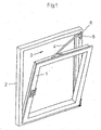
- Fig. 1 shows slightly schematically a wing 1 of a tilt-and-turn window, which is pivotable about a lower horizontal and a lateral vertical axis.
- the wing 1 is connected at its upper horizontal wing leg with the frame 2 via a display device 3.
- the opening device 3 is provided with a stay arm 4, which is pivotally and slidably mounted at one end to the horizontal wing leg and the other end is associated with a pivot bearing 5.
- the pivot bearing 5 consists of a frame 2 to be fixed to the bearing block 6 and a wing part 7, which is pivotally connected to the bearing block 6 by means of a sleeve 8 of the wing part 7 passing through hinge pin 9, as a comparison with the Fig. 2 shows.
- a sleeve 8 of the wing part 7 passing through hinge pin 9, as a comparison with the Fig. 2 shows.
- adjoins the sleeve 8 an angled hinge tabs 10 adjoins the sleeve 8 an angled hinge tabs 10, the fastening tabs 11 is used for coupling with an angled leg 12 of the stay 4.
- an elbow is provided, which is connected with a leg on the stay 4 and forms the leg 12 with the other leg.
- FIG. 3 and 4 is the connection of the leg 12 of the stay 4 and the mounting tab 11 recognizable.
- the mounting tabs 11 is provided on its the leg 12 associated surface with a substantially T-shaped ridge 13.
- the web 13 forms two form-locking elements (webs 13.1 and 13.2) by the web 13 is interrupted transversely to its axis of symmetry.
- the web 13.1 or 13.2 passes through in its illustrated functional position ( Fig. 3 ) the leg 12 of the stay 4 in openings or recesses 14, 15, in the Fig. 6 are recognizable.
- the recess 14 is designed as an open-edged slot, while the recess 15 as a closed recess a slot 16 with an extension 17 for the passage of one of the T-shaped webs 13.1 and 13.2 contains.
- the widened head of the web 13 or the webs 13.1 and 13.2 engages behind the longitudinal edges of the recesses 14, 15 in the region of the narrower sections.
- At least the recess 15 may have an L-shaped contour in which a leg opens on a longitudinal edge of the leg 12.
- the web can be inserted 13.1 or 13.2 with his foot in the recess laterally on the leg and be displaced by longitudinal displacement in its functional position.
- this embodiment reduces the stability of the angled leg due to the open-edged recess.
- the attachment of the wing portion 7 to the leg 12 is carried out in a conventional manner in that one of the webs -zB web 13.1 is inserted into the extension 17 of the recess 15 which is dimensionally adapted to the widened head of the web 13.
- the lying between the recesses 14, 15 section 18 of the leg 12 is located between the webs 13.1 and 13.2, which have an interruption 19 here.
- longitudinal displacement of the web 13.1 is now in the narrow and tuned to the foot of the web 13 slot 16 and the web 13.2 moved into the slot 14.
- the hinge flap 11 and the leg 12 in the direction 21 and opposite thereto is fixed to each other.
- the webs 13.1 and 13.2 are formed from the web 13, as shown in Fig. 5 seen.
- the web 13 is broken by means of a bore 20.
- a sufficiently large interruption 19 of the web 13 is effected in a single operation in a simple manner, which can also be carried out very easily and dimensionally stable beyond.
- the bore 20 is designed as a flat cylindrical recess on the fastening tabs 11. This avoids a weakening of the fastening tab 11 and the bore 20 can be produced as a flat blind hole, for example by means of an end mill.
- the leg 12 is held on the fastening tabs 11 by means of a securing element 22.
- the securing element 22 consists of a leaf spring 23 which lies centrally between the two webs 13.1 and 13.2, which act as form-locking elements, in the region of the interruption 19 or the bore 20.
- the leaf spring 23 is partially received in the bore 20 and at least partially has an approximately circular and the bore 20 adapted circumference 24.
- the leaf spring 23 is already fixed at least in the longitudinal direction of the web 13 and does not bear on the fastening tabs 11. Otherwise, it would be necessary to provide a corresponding free space between the fastening tabs 12 and the legs 11.
- the bore 20 used to make the interruption 19 can simultaneously provide the space necessary to accommodate the leaf spring 23.
- the bore 20 and the matching circumference 24 also allow a certain fixing of the leaf spring 23 transversely to the web 13 - in the direction 25 (FIG. Fig. 5 ), since due to the production of the interruption 19, the edge 26 forms a slight undercut in this direction.
- the undercut through the edge 26 can be used, for example, during assembly of the leaf spring 23 on the pivot bearing 5 to a short-term Fixation bring about.
- it is more advantageous for an alignment if the leaf spring 23 has an angled web 27, which rests against the lateral edge 28 of the fastening tab 11. As a result, the leaf spring 23 receives a counter to the direction 25 acting defined orientation relative to the mounting tabs 11 and is also aligned within the bore 20 at right angles to the mounting tabs 11.
- the function of the leaf spring 23 is readily apparent: When mounting the wing portion 7 on the leg 12, the portion 18 is disposed within the interruption 19 and the bore 20, as already described above. The section 18 acts on the spring tongue 29, which is thereby pivoted in the direction 21 in the flat bore 20 into it. During the subsequent displacement of the wing part 7, the portion 18 is displaced so far relative to the wing part 7 that it lies between the edge 30 of the spring tongue 29 and the web 13.1 or 13.2. If the spring tongue 29 now springs back, it lies between the spring tongue 29 and the web 13.1 or 13.2, so that a pushing back is only possible with simultaneous deformation of the leaf spring 23.
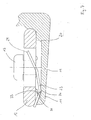
- the fastening tabs 11 has a parallel to the pivot bearing axis, so the sleeve 8, extending shoulder 33, on which the leaf spring 23 abuts at least partially.
- This can be done, for example, by means of a wing 34 (FIG. Fig. 5 ), which lies laterally next to the circular arc-shaped section engaging in the bore 20.
- the wing 34 ends at an edge parallel to the pivot bearing axis edge, which comes to rest near the shoulder 33.
- the shoulder 33 can be partially deformed, for example, by means of a forming punch, so that the deformed material portion 35 - as in Fig. 7 indicated - the leaf spring 23 partially overlapped.
- the shoulder 33 is clearly adjacent to the widened head of the web 13 so that the shoulder 33 is easily accessible with the forming punch.
Landscapes
- Engineering & Computer Science (AREA)
- Mechanical Engineering (AREA)
- Hinges (AREA)
- Closing And Opening Devices For Wings, And Checks For Wings (AREA)
- Dental Tools And Instruments Or Auxiliary Dental Instruments (AREA)
Description
- Gegenstand der Erfindung ist eine Ausstellvorrichtung nach dem Oberbegriff des Anspruchs 1.
- Aus der
EP 0666 398 B1 undDE 40 40 233 A1 ist eine Ausstellvorrichtung für ein Fenster oder eine Tür bekannt geworden, die einen Ausstellarm aufweist, der einerends am Flügel schwenkbar und längsverschiebbar zu lagern und anderenends lösbar mit einem Schwenklager kuppelbar ist. Das Schwenklager besteht aus einem am Blendrahmen zu befestigenden Lagerbock und einem Flügelteil, das mit dem Lagerbock mittels eines eine Hülse des Flügelteils durchsetzenden Gelenkbolzens schwenkbar verbunden ist. An die Hülse schließt sich ein abgewinkelter Bandlappen an, dessen Befestigungslappen zur Kopplung mit einem in Richtung der Schwenkachse abgewinkelten Schenkel des Ausstellarms vorgesehen ist. Dazu weist in derEP 0 666 398 81 - In der
DE 40 40 233 A1 weist der Bandlappen ein Rückhalteelement mit hammerförmigem Kopf auf, der in eine schlüssellochförmige Öffnung im Schenkel des Ausstellarms eingeführt werden kann. Nach Verdrehen um 90 Grad übergreift der hammerförmige Kopf die Ränder der schlüssellochförmigen Öffnung. In dieser Montageposition umgreift eine, auf den Schenkel des Ausstellarms aufgesetzte, Blattfeder mit einer Ausnehmung die Außenkontur des hammerförmigen Kopfes, um ein Rückstellen zu verhindern. - Aus dem DE-GM 1 923 282 ist es ferner bekannt, einen Ausstellarm mit einem Scharnierteil über eine Renkverbindung miteinander zu verbinden. Der Ausstellarm weist dazu zwei im Abstand zueinander angeordnete Pilzzapfen auf, deren Lage abgestimmt ist mit zwei schlüssellochartigen Ausnehmungen an dem Scharnierteil. In die Erweiterungen der schlüssellochförmigen Ausnehmungen lassen sich die Pilzzapfen einführen, sodass die verbreiterten Köpfe nach einem Verschieben in die Funktionsstellung die Ränder des schmalen Abschnitts Ausnehmungen hintergreifen. Um auch hier ein unerwünschtes Verschieben aus der Funktionsstellung zu vermeiden ist eine Blattfeder vorgesehen, welche an dem Ausstellarm vorgesehen wird und welche bei der Montage des Scharnierteils zunächst durch dieses weggedrückt wird und nach dem Erreichen der Funktionsstellung eine Querkante des Scharnierteils hintergreift, so dass eine Bewegung in entgegengesetzter Richtung zur Montagerichtung gesperrt ist.
- Aufgabe der Erfindung ist es, eine möglichst einfache Verbindung des Ausstellarms und des Bandlappens zu erreichen, welche eine einfache Herstellung der beteiligten Bauteile zulässt.
- Die Lösung dieser Aufgabe gelingt mit den Merkmalen des Anspruchs 1. Es wird auf diese Weise eine Herstellung des Bandlappens aus einem gezogenen Profilteil möglich, welches nur einer geringen Nacharbeit zur Unterbrechung des Steges bedarf. Der Ausstellarm ist nur mit einfach herzustellenden Ausnehmungen zu versehen. Die Anordnung der Blattfeder an dem Befestigungslappen erleichtert die Handhabung bei der Montage, da auf diese Weise nur das geringere Abmessungen aufweisende Flügelteil bewegt werden muss. Die mittige Anordnung gewährleistet dabei die Verwendung für nach links und nach rechts öffnenbare Flügel.
- Es ist ferner vorgesehen, dass der Steg mittels einer Bohrung durchbrochen wird. Dadurch wird in einem Arbeitsgang eine hinreichend große Unterbrechung des Steges, die darüber hinaus auch sehr einfach und maßhaltig ausgeführt werden kann.
- Um eine Schwächung des Befestigungslappens zu vermeiden ist es von Vorteil, wenn die Bohrung als zylindrische Ausnehmung an dem Befestigungslappen ausgeführt ist. Dies kann beispielsweise mittels eines Schaftfräsers erreicht werden.
- Es kann auch vorgesehen werden, dass die Blattfeder abschnittsweise in der Bohrung aufgenommen ist und zumindest bereichsweise einen annähernd kreisförmigen und an die Bohrung angepassten Umfang hat. Dadurch ist die Blattfeder bereits in Längsrichtung des Steges festgelegt.
- Die Befestigung der Blattfeder kann noch dadurch verbessert werden, dass die Blattfeder einen abgewinkelten Steg aufweist, der an dem Befestigungslappen seitlich anliegt. Hierdurch ergibt sich eine Montageerleichterung, da die Blattfeder auch in dieser Richtung eine definierte Ausrichtung relativ zum Befestigungslappen erhält.
- Zur unverlierbaren Befestigung der Blattfeder kann ferner vorgesehen werden, dass der Befestigungslappen einen parallel zur Schwenklagerachse verlaufenden Absatz aufweist, an dem die Blattfeder zumindest bereichsweise anliegt. Dieser Absatz kann abschnittsweise verformt werden, so dass der verformte Teil die Blattfeder teilweise überlappt.
- Um die Stabilität des abgewinkelten Schenkel des Ausstellarms zu erhalten ist vorgesehen, dass der Befestigungslappen eine randoffene und eine geschlossene Ausnehmung enthält, wobei die randoffene Ausnehmung als Schlitz ausgebildet ist und die geschlossene Ausnehmung einen Schlitz mit einer Erweiterung zum Durchtritt eines der T-förmigen Stege enthält. Abweichend davon kann nämlich vorgesehen sein, dass zumindest eine der Ausnehmungen L-förmig und seitlich offen ist, so dass der Steg in die Ausnehmung seitlich am Schenkel eingeführt werden kann und durch längsverschieben in seine Funktionsstellung verlagert wird.
- Weitere vorteilhafte Ausgestaltungen ergeben sich aus den Fig. Es zeigt:
- Fig. 1
- ein Drehkippfenster mit einem gekippten Flügel,
- Fig. 2
- in einem größeren Maßstab den Lagerbock der Ausstellvorrichtung mit dem daran befestigten Ausstellarm,
- Fig. 3
- einen Schnitt entlang der Linie III-III in
Fig. 2 , - Fig. 4
- einen Schnitt entlang der Linie IV-IV in
Fig. 5 mit dem eingerasteten Sicherungselement, - Fig. 5
- das Flügelteil mit dem Befestigungsteil in einer Draufsicht,
- Fig. 6
- den Schenkel des Ausstellarms und
- Fig. 7
- in einer vergrößerten Darstellung die Verbindung des Sicherungselementes mit dem Befestigungslappen.
-
Fig. 1 zeigt leicht schematisiert einen Flügel 1 eines Drehkipp-Fensters, der um eine untere horizontale und eine seitliche vertikale Achse schwenkbar ist. Dazu ist der Flügel 1 an seinem oberen horizontalen Flügelschenkel mit dem Blendrahmen 2 über eine Ausstellvorrichtung 3 verbunden. Die Ausstellvorrichtung 3 ist mit einem Ausstellarm 4 versehen, der einenends an dem horizontalen Flügelschenkel schwenk- und verschiebbar gelagert ist und anderenends einem Schwenklager 5 zugeordnet ist. - Das Schwenklager 5 besteht aus einem am Blendrahmen 2 zu befestigenden Lagerbock 6 und einem Flügelteil 7, das mit dem Lagerbock 6 mittels eines eine Hülse 8 des Flügelteils 7 durchsetzenden Gelenkbolzens 9 schwenkbar verbunden ist, wie ein Vergleich mit der
Fig. 2 zeigt. Wie auch in Verbindung mit derFig. 3 ersichtlich, schließt sich an die Hülse 8 ein abgewinkelter Bandlappen 10 an, dessen Befestigungslappen 11 zur Kopplung mit einem abgewinkelten Schenkel 12 des Ausstellarms 4 dient. - Es kann aber abweichend von der Darstellung nach
Fig. 2 und 3 auch vorgesehen werden, dass anstelle der einteiligen Ausgestaltung des Ausstellarms 4 ein Winkelstück vorgesehen wird, welches mit einem Schenkels an dem Ausstellarm 4 angeschlossen ist und mit dem anderen Schenkel den Schenkel 12 bildet. - In den
Fig. 3 und4 ist die Verbindung des Schenkels 12 des Ausstellarms 4 und des Befestigungslappens 11 erkennbar. Der Befestigungslappen 11 ist auf seiner dem Schenkel 12 zugeordneten Fläche mit einen im wesentlichen T-förmigen Steg 13 versehen. - Ausweislich der
Fign. 3 bis 6 bildet der Steg 13 zwei Formschlusselemente (Stege 13.1 und 13.2), indem der Steg 13 quer zu seiner Symmetrieachse unterbrochen wird. Der Steg 13.1 bzw. 13.2 durchgreift in seiner dargestellten Funktionsstellung (Fig. 3 ) den Schenkel 12 des Ausstellarms 4 in Öffnungen oder Ausnehmungen 14, 15, die in derFig. 6 erkennbar sind. Die Ausnehmung 14 ist dabei als randoffener Schlitz ausgebildet, während die Ausnehmung 15 als geschlossene Ausnehmung einen Schlitz 16 mit einer Erweiterung 17 zum Durchtritt eines der T-förmigen Stege 13.1 bzw. 13.2 enthält. Der verbreiterte Kopf des Stegs 13 (bzw. der Stege 13.1 und 13.2 hintergreift dabei die Längsränder der Ausnehmungen 14, 15 im Bereich der engeren Abschnitte. - Abweichend davon kann nämlich vorgesehen sein, dass zumindest die Ausnehmung 15 eine L-förmige Kontur erhält, bei der ein Schenkel an einer Längskante des Schenkels 12 mündet. Dadurch kann der Steg 13.1 oder 13.2 mit seinem Fuß in die Ausnehmung seitlich am Schenkel eingeführt werden und durch längsverschieben in seine Funktionsstellung verlagert werden. Diese Ausgestaltung mindert durch die randoffene Ausnehmung jedoch die Stabilität des abgewinkelten Schenkels.
- Die Befestigung des Flügelteils 7 an dem Schenkel 12 erfolgt in an sich bekannter Weise dadurch, dass einer der Stege -z.B. Steg 13.1 in die Erweiterung 17 der Ausnehmung 15 eingeführt wird, die dazu maßlich an den verbreiterten Kopf des Stegs 13 angepasst ist. Der zwischen den Ausnehmungen 14, 15 liegende Abschnitt 18 des Schenkels 12 liegt dazu zwischen den Stegen 13.1 und 13.2, die hier eine Unterbrechung 19 aufweisen. Durch ein Längsverschieben wird der Steg 13.1 nun in den schmalen und auf den Fuß des Steges 13 abgestimmten Schlitz 16 und der Steg 13.2 in den Schlitz 14 verschoben. Dadurch ist der Bandlappen 11 und der Schenkel 12 in Richtung 21 und entgegengesetzt dazu aneinander festgelegt.
- Durch die Unterbrechung 19 werden die Stege 13.1 und 13.2 aus dem Steg 13 gebildet, wie aus der
Fig. 5 ersichtlich. Wie hier auch erkennbar ist vorgesehen, dass der Steg 13 mittels einer Bohrung 20 durchbrochen wird. Dadurch wird in einem Arbeitsgang eine hinreichend große Unterbrechung 19 des Steges 13 auf einfache Weise bewirkt, die darüber hinaus auch sehr einfach und maßhaltig ausgeführt werden kann. In Verbindung mit derFig. 4 wird deutlich, dass die Bohrung 20 als flache zylindrische Ausnehmung an dem Befestigungslappen 11 ausgeführt ist. Dies vermeidet eine Schwächung des Befestigungslappens 11 und die Bohrung 20 kann als flache Sacklochbohrung beispielsweise mittels eines Schaftfräsers hergestellt werden. - Um ein Lösen der Verbindung von Befestigungslappen und Schenkel 12 zu verhindern ist vorgesehen, dass der Schenkel 12 mittels eines Sicherungselements 22 am Befestigungslappen 11 gehalten ist. Das Sicherungselement 22 besteht aus einer Blattfeder 23, die mittig zwischen den zwei als Formschlusselementen wirksamen Stegen 13.1 und 13.2 im Bereich der Unterbrechung 19 bzw. der Bohrung 20 liegt.
- Von besonderem Vorteil ist dabei die Ausgestaltung nach
Fig. 5 , bei der die Blattfeder 23 abschnittsweise in der Bohrung 20 aufgenommen ist und zumindest bereichsweise einen annähernd kreisförmigen und an die Bohrung 20 angepassten Umfang 24 hat. Dadurch ist die Blattfeder 23 nämlich bereits zumindest in Längsrichtung des Steges 13 festgelegt und trägt nicht auf den Befestigungslappen 11 auf. Anderenfalls wäre es nämlich notwendig, zwischen dem Befestigungslappen 12 und dem Schenkel 11 einen entsprechenden Freiraum vorzusehen. So kann die zur Herstellung der Unterbrechung 19 verwendete Bohrung 20 gleichzeitig den zur Unterbringung der Blattfeder 23 notwendigen Raum schaffen. Die Bohrung 20 und der darauf abgestimmte Umfang 24 erlauben aber darüber hinaus auch eine gewisse Festlegung der Blattfeder 23 quer zu dem Steg 13 - in Richtung 25 (Fig. 5 ), da bedingt durch die Herstellung der Unterbrechung 19 die Kante 26 in dieser Richtung einen geringen Hinterschnitt bildet. - Der Hinterschnitt durch die Kante 26 kann beispielsweise bei der Montage der Blattfeder 23 an dem Schwenklager 5 verwendet werden, um eine kurzzeitige Fixierung herbei zu führen. Vorteilhafter für eine Ausrichtung ist es jedoch, wenn die Blattfeder 23 einen abgewinkelten Steg 27 aufweist, der an dem seitlichen Rand 28 des Befestigungslappens 11 anliegt. Hierdurch erhält die Blattfeder 23 eine entgegen der Richtung 25 wirkende definierte Ausrichtung relativ zum Befestigungslappen 11 und wird gleichzeitig auch innerhalb der Bohrung 20 rechtwinklig zum Befestigungslappen 11 ausgerichtet.
- Die Funktion der Blattfeder 23 ist leicht ersichtlich: Bei der Montage des Flügelteils 7 an dem Schenkel 12 wird der Abschnitt 18 innerhalb der Unterbrechung 19 bzw. der Bohrung 20 angeordnet, wie vorstehend bereits beschrieben. Der Abschnitt 18 wirkt dabei auf die Federzunge 29, die dadurch in Richtung 21 in die flache Bohrung 20 hinein verschwenkt wird. Beim anschließenden Verschieben des Flügelteils 7 wird der Abschnitt 18 relativ zum Flügelteil 7 so weit verlagert, dass dieser zwischen dem Rand 30 der Federzunge 29 und dem Steg 13.1 bzw. 13.2 liegt. Springt die Federzunge 29 nun zurück, so liegt sie zwischen der Federzunge 29 und dem Steg 13.1 bzw. 13.2, so dass ein Zurückschieben nur unter gleichzeitiger Verformung der Blattfeder 23 möglich ist.
- Es ist leicht ersichtlich, dass dazu der lichte Abstand der Federzunge 29 und des Steges 13.1 oder 13.2 etwas größer bemessen sein muss als die Länge (entlang der Mittelachse 32) des Anschnitts 18. Es ist aus der
Fig. 4 und auch derFig. 7 erkennbar, dass die Federzunge 29 so gebogen ist, dass sie in den Bereich des Schenkels 12 vorragt. - Zur unverlierbaren Befestigung der Blattfeder. Hierzu ist vorgesehen, dass der Befestigungslappen 11 einen parallel zur Schwenklagerachse, also der Hülse 8, verlaufenden Absatz 33 aufweist, an dem die Blattfeder 23 zumindest bereichsweise anliegt. Dies kann beispielsweise mittels eines Flügels 34 (
Fig. 5 ) erfolgen, der seitlich neben dem in die Bohrung 20 eingreifenden kreisbogenförmigen Abschnitt liegt. Der Flügel 34 endet an einer zur Schwenklagerachse parallelverlaufenden Kante, welche nahe dem Absatz 33 zu liegen kommt. Der Absatz 33 kann abschnittsweise z.B. mittels eines Formstempels verformt werden, so dass der verformte Materialabschnitt 35 - wie inFig 7 angedeutet - die Blattfeder 23 teilweise überlappt. - Für diese Ausgestaltung ist es zweckmäßig, dass der Absatz 33 deutlich neben dem verbreiterten Kopf des Stegs 13 liegt, damit der Absatz 33 mit dem Formstempel leicht erreichbar ist.
- Durch die beschriebene Ausgestaltung ist eine Herstellung des Flügelteils 7 aus einem gezogenen Profil leicht möglich, da zur Herstellung der Funktion ausschließlich eine Nachbearbeitung notwendig ist.
-
- 1
- Flügel
- 2
- Rahmen
- 3
- Ausstellvorrichtung
- 4
- Ausstellarm
- 5
- Schwenklager
- 6
- Lagerbock
- 7
- Flügelteil
- 8
- Hülse
- 9
- Gelenkbolzen
- 10
- Bandlappen
- 11
- Befestigungslappen
- 12
- Schenkel
- 13
- Steg
- 13.1
- Steg
- 13.2
- Steg
- 14
- Ausnehmung
- 15
- Ausnehmung
- 16
- Schlitz
- 17
- Erweiterung
- 18
- Abschnitt
- 19
- Unterbrechung
- 20
- Bohrung
- 21
- Richtung
- 22
- Sicherungselement
- 23
- Blattfeder
- 24
- Umfang
- 25
- Richtung
- 26
- Kante
- 27
- Steg
- 28
- Rand
- 29
- Federzunge
- 30
- Rand
- 32
- Mittelachse
- 33
- Absatz
- 34
- Flügel
- 35
- Materialabschnitt
Claims (7)
- Ausstellvorrichtung für Fenster, Türen, insbesondere mit Drehkippflügel, mit mindestens einem Ausstellarm (4), der einerends an einem Flügel (1) schwenkbar und längsverschiebbar zu lagern und anderenends lösbar mit einem Schwenklager (5) der Ausstellvorrichtung kuppelbar ist, wobei das Schwenklager (5) aus einem an einem Blendrahmen (2) zu befestigenden Lagerbock (6) und einem Flügelteil (7) besteht, das mit dem Lagerbock (6), mittels eines eine Hülse (8) des Flügelteils (7) durchsetzenden Gelenkbolzens (9), schwenkbar verbunden ist, wobei sich an die Hülse (8) ein abgewinkelter Bandlappen (10) anschließt, dessen Befestigungslappen (11) zur Kopplung mit einem abgewinkelten Schenkel (12) des Ausstellarms (4) oder mit einem Schenkels eines an dem Ausstellarm (4) angeschlossenen Winkelstücks vorgesehen ist, und wobei der Schenkel (12) mittels eines Sicherungselements (22) am Befestigungslappen (11) gehalten ist, wobei das Sicherungselement (22) aus einer Blattfeder (23) besteht, dadurch gekennzeichnet, dass die Blattfeder (23) mittig zwischen zwei Formschlusselementen (13.1, 13.2) liegt, dass die Formschlusselemente (13.1, 13.2) von einem unterbrochenen und im Querschnitt T-förmigen Steg (13) des Befestigungslappens (11) gebildet werden, und dass die Formschlusselemente (13.1, 13.2) in Öffnungen bzw. Ausnehmungen (14, 15) des Schenkels (12) einführbar sind und durch längsverschieben in ihre Funktionsstellung verlagert werden, in der sie die Öffnungen bzw. Ausnehmungen (14, 15) hintergreifen.
- Ausstellvorrichtung nach Anspruch 1, dadurch gekennzeichnet, dass der Steg (13) mittels einer Bohrung (20) durchbrochen wird.
- Ausstellvorrichtung nach Anspruch 2, dadurch gekennzeichnet, dass die Bohrung (20) als zylindrische Ausnehmung an dem Befestigungslappen (11) ausgeführt ist.
- Ausstellvorrichtung nach Anspruch 2 oder 3, dadurch gekennzeichnet, dass die Blattfeder (23) abschnittsweise in der Bohrung (20) aufgenommen ist und zumindest bereichsweise einen annähernd kreisförmigen und an die Bohrung (20) angepassten Umfang (24) hat.
- Ausstellvorrichtung nach einem der Ansprüche 1 bis 4, dadurch gekennzeichnet, dass die Blattfeder (23) einen abgewinkelten Steg (27) aufweist, der an dem Befestigungslappen (11) seitlich anliegt.
- Ausstellvorrichtung nach einem der Ansprüche 1 bis 5, dadurch gekennzeichnet, dass der Befestigungslappen (11) einen parallel zur Schwenklagerachse verlaufenden Absatz (33) aufweist, an dem die Blattfeder (23) zumindest bereichsweise anliegt.
- Ausstellvorrichtung nach einem der Ansprüche 1 bis 6, dadurch gekennzeichnet, dass der Befestigungslappen (11) eine randoffene und eine geschlossene Ausnehmung (14, 15) enthält, wobei die randoffene Ausnehmung (14) als Schlitz ausgebildet ist und die geschlossene Ausnehmung (15) einen Schlitz (16) mit einer Erweiterung (17) zum Durchtritt eines der T-förmigen Stege (13.1, 13.2) enthält.
Applications Claiming Priority (2)
| Application Number | Priority Date | Filing Date | Title |
|---|---|---|---|
| DE202004004927U | 2004-03-26 | ||
| DE202004004927U DE202004004927U1 (de) | 2004-03-26 | 2004-03-26 | Ausstellvorrichtung |
Publications (3)
| Publication Number | Publication Date |
|---|---|
| EP1580379A2 EP1580379A2 (de) | 2005-09-28 |
| EP1580379A3 EP1580379A3 (de) | 2009-07-15 |
| EP1580379B1 true EP1580379B1 (de) | 2010-06-02 |
Family
ID=34854235
Family Applications (1)
| Application Number | Title | Priority Date | Filing Date |
|---|---|---|---|
| EP05100856A Expired - Lifetime EP1580379B1 (de) | 2004-03-26 | 2005-02-08 | Ausstellvorrichtung für die Flügel von Fenstern, Türen od. dgl |
Country Status (4)
| Country | Link |
|---|---|
| EP (1) | EP1580379B1 (de) |
| AT (1) | ATE470039T1 (de) |
| DE (2) | DE202004004927U1 (de) |
| ES (1) | ES2343416T3 (de) |
Family Cites Families (3)
| Publication number | Priority date | Publication date | Assignee | Title |
|---|---|---|---|---|
| DE1923282U (de) * | 1965-06-30 | 1965-09-09 | Hans Bilstein | Ausstellstange fuer dreh-kipp-fenster od. dgl. |
| DE4040233C2 (de) * | 1990-12-15 | 1994-11-03 | Bilstein August Gmbh Co Kg | Schwenklager an einer Ausstellvorrichtung von Dreh-Kipp-Flügeln von Fenstern, Türen oder dergleichen |
| DE9401699U1 (de) * | 1994-02-02 | 1994-03-17 | Roto Frank Ag, 70771 Leinfelden-Echterdingen | Ausstellvorrichtung für Fenster, Türen o.dgl. |
-
2004
- 2004-03-26 DE DE202004004927U patent/DE202004004927U1/de not_active Expired - Lifetime
-
2005
- 2005-02-08 DE DE502005009662T patent/DE502005009662D1/de not_active Expired - Lifetime
- 2005-02-08 ES ES05100856T patent/ES2343416T3/es not_active Expired - Lifetime
- 2005-02-08 EP EP05100856A patent/EP1580379B1/de not_active Expired - Lifetime
- 2005-02-08 AT AT05100856T patent/ATE470039T1/de active
Also Published As
| Publication number | Publication date |
|---|---|
| EP1580379A2 (de) | 2005-09-28 |
| DE502005009662D1 (de) | 2010-07-15 |
| EP1580379A3 (de) | 2009-07-15 |
| ATE470039T1 (de) | 2010-06-15 |
| DE202004004927U1 (de) | 2005-08-11 |
| ES2343416T3 (es) | 2010-07-30 |
Similar Documents
| Publication | Publication Date | Title |
|---|---|---|
| EP0403731B1 (de) | Ausstellvorrichtung für die Flügel von Fenstern, Türen od. dgl. | |
| EP2105564A2 (de) | Beschlag für eine Ausstell- und Kippbewegung eines Flügels eines Gebäudefensters oder einer Gebäudetür | |
| EP1072745A1 (de) | Beschlag für die Verriegelung von Fenstern oder Türen | |
| EP2754813B1 (de) | Band, insbesondere für Kunststoff-Türen und -Fenster | |
| EP1411201B1 (de) | Beschlag | |
| EP1223276A2 (de) | Bandanordnung für Türen, Fenster und dergleichen | |
| EP0628688B1 (de) | Lager für die wenigstens drehbare Lagerung eines Flügels, eines Fensters, einer Tür oder dergleichen | |
| DE8526659U1 (de) | Flügellager für ein Fenster, eine Tür od. dgl. | |
| EP1580379B1 (de) | Ausstellvorrichtung für die Flügel von Fenstern, Türen od. dgl | |
| DE8804008U1 (de) | Scharnier | |
| EP1197623A1 (de) | Scharnier | |
| EP1512817B1 (de) | Band für Türen, Fenster oder dergleichen | |
| EP0730074B1 (de) | Kantriegelbeschlag für Standflügel von doppelflügeligen Türen | |
| EP1759081B1 (de) | Ausstellvorrichtung | |
| DE20012351U1 (de) | Fenster oder Tür mit Entlastungseinrichtung | |
| DE9301655U1 (de) | Scharnierbeschlag | |
| EP0924375A1 (de) | Scharnierbeschlag für den einen Überschlag aufweisenden Flügel eines Fensters, einer Tür oder dergleichen | |
| EP1979567A1 (de) | Bandanordnung zur scharniergelenkigen verbindung eines flügels einer tür, eines fensters oder dergleichen, an einem rahmen | |
| DE102019134407A1 (de) | Beschlaganordnung | |
| EP2811093B1 (de) | An einem Blendrahmen einer Tür oder eines Fensters festlegbares Trägerteil eines Schwenkbeschlages | |
| DE60115160T2 (de) | Zwischenbeschlag für Tür oder Fenster für nicht sichtbaren Scharnierbeschlag | |
| DE1011773B (de) | Beschlag fuer Kipp-Schwenk-Fluegel von Fenstern, Tueren od. dgl. mit einem Gestaenge zum Aus- und Einkuppeln der Kipp- und Schwenkscharniere | |
| DE2727585C2 (de) | Nachstellbares Lenker-Drehlager für Kipp-Schwenkfenster oder -türen | |
| EP3205803B1 (de) | Vorrichtung zur dämpfung und begrenzung einer öffnungsbewegung | |
| CH562386A5 (de) |
Legal Events
| Date | Code | Title | Description |
|---|---|---|---|
| PUAI | Public reference made under article 153(3) epc to a published international application that has entered the european phase |
Free format text: ORIGINAL CODE: 0009012 |
|
| AK | Designated contracting states |
Kind code of ref document: A2 Designated state(s): AT BE BG CH CY CZ DE DK EE ES FI FR GB GR HU IE IS IT LI LT LU MC NL PL PT RO SE SI SK TR |
|
| AX | Request for extension of the european patent |
Extension state: AL BA HR LV MK YU |
|
| PUAL | Search report despatched |
Free format text: ORIGINAL CODE: 0009013 |
|
| AK | Designated contracting states |
Kind code of ref document: A3 Designated state(s): AT BE BG CH CY CZ DE DK EE ES FI FR GB GR HU IE IS IT LI LT LU MC NL PL PT RO SE SI SK TR |
|
| AX | Request for extension of the european patent |
Extension state: AL BA HR LV MK YU |
|
| 17P | Request for examination filed |
Effective date: 20090819 |
|
| GRAP | Despatch of communication of intention to grant a patent |
Free format text: ORIGINAL CODE: EPIDOSNIGR1 |
|
| AKX | Designation fees paid |
Designated state(s): AT BE BG CH CY CZ DE DK EE ES FI FR GB GR HU IE IS IT LI LT LU MC NL PL PT RO SE SI SK TR |
|
| GRAF | Information related to payment of grant fee modified |
Free format text: ORIGINAL CODE: EPIDOSCIGR3 |
|
| GRAS | Grant fee paid |
Free format text: ORIGINAL CODE: EPIDOSNIGR3 |
|
| GRAA | (expected) grant |
Free format text: ORIGINAL CODE: 0009210 |
|
| AK | Designated contracting states |
Kind code of ref document: B1 Designated state(s): AT BE BG CH CY CZ DE DK EE ES FI FR GB GR HU IE IS IT LI LT LU MC NL PL PT RO SE SI SK TR |
|
| REG | Reference to a national code |
Ref country code: GB Ref legal event code: FG4D Free format text: NOT ENGLISH |
|
| REG | Reference to a national code |
Ref country code: CH Ref legal event code: EP |
|
| REG | Reference to a national code |
Ref country code: IE Ref legal event code: FG4D Free format text: LANGUAGE OF EP DOCUMENT: GERMAN |
|
| REF | Corresponds to: |
Ref document number: 502005009662 Country of ref document: DE Date of ref document: 20100715 Kind code of ref document: P |
|
| REG | Reference to a national code |
Ref country code: ES Ref legal event code: FG2A Ref document number: 2343416 Country of ref document: ES Kind code of ref document: T3 |
|
| REG | Reference to a national code |
Ref country code: NL Ref legal event code: VDEP Effective date: 20100602 |
|
| PG25 | Lapsed in a contracting state [announced via postgrant information from national office to epo] |
Ref country code: LT Free format text: LAPSE BECAUSE OF FAILURE TO SUBMIT A TRANSLATION OF THE DESCRIPTION OR TO PAY THE FEE WITHIN THE PRESCRIBED TIME-LIMIT Effective date: 20100602 Ref country code: SE Free format text: LAPSE BECAUSE OF FAILURE TO SUBMIT A TRANSLATION OF THE DESCRIPTION OR TO PAY THE FEE WITHIN THE PRESCRIBED TIME-LIMIT Effective date: 20100602 |
|
| LTIE | Lt: invalidation of european patent or patent extension |
Effective date: 20100602 |
|
| PG25 | Lapsed in a contracting state [announced via postgrant information from national office to epo] |
Ref country code: FI Free format text: LAPSE BECAUSE OF FAILURE TO SUBMIT A TRANSLATION OF THE DESCRIPTION OR TO PAY THE FEE WITHIN THE PRESCRIBED TIME-LIMIT Effective date: 20100602 Ref country code: SI Free format text: LAPSE BECAUSE OF FAILURE TO SUBMIT A TRANSLATION OF THE DESCRIPTION OR TO PAY THE FEE WITHIN THE PRESCRIBED TIME-LIMIT Effective date: 20100602 |
|
| PG25 | Lapsed in a contracting state [announced via postgrant information from national office to epo] |
Ref country code: CY Free format text: LAPSE BECAUSE OF FAILURE TO SUBMIT A TRANSLATION OF THE DESCRIPTION OR TO PAY THE FEE WITHIN THE PRESCRIBED TIME-LIMIT Effective date: 20100602 Ref country code: PL Free format text: LAPSE BECAUSE OF FAILURE TO SUBMIT A TRANSLATION OF THE DESCRIPTION OR TO PAY THE FEE WITHIN THE PRESCRIBED TIME-LIMIT Effective date: 20100602 |
|
| REG | Reference to a national code |
Ref country code: IE Ref legal event code: FD4D |
|
| PG25 | Lapsed in a contracting state [announced via postgrant information from national office to epo] |
Ref country code: IE Free format text: LAPSE BECAUSE OF FAILURE TO SUBMIT A TRANSLATION OF THE DESCRIPTION OR TO PAY THE FEE WITHIN THE PRESCRIBED TIME-LIMIT Effective date: 20100602 Ref country code: NL Free format text: LAPSE BECAUSE OF FAILURE TO SUBMIT A TRANSLATION OF THE DESCRIPTION OR TO PAY THE FEE WITHIN THE PRESCRIBED TIME-LIMIT Effective date: 20100602 Ref country code: EE Free format text: LAPSE BECAUSE OF FAILURE TO SUBMIT A TRANSLATION OF THE DESCRIPTION OR TO PAY THE FEE WITHIN THE PRESCRIBED TIME-LIMIT Effective date: 20100602 |
|
| PG25 | Lapsed in a contracting state [announced via postgrant information from national office to epo] |
Ref country code: IS Free format text: LAPSE BECAUSE OF FAILURE TO SUBMIT A TRANSLATION OF THE DESCRIPTION OR TO PAY THE FEE WITHIN THE PRESCRIBED TIME-LIMIT Effective date: 20101002 Ref country code: SK Free format text: LAPSE BECAUSE OF FAILURE TO SUBMIT A TRANSLATION OF THE DESCRIPTION OR TO PAY THE FEE WITHIN THE PRESCRIBED TIME-LIMIT Effective date: 20100602 Ref country code: RO Free format text: LAPSE BECAUSE OF FAILURE TO SUBMIT A TRANSLATION OF THE DESCRIPTION OR TO PAY THE FEE WITHIN THE PRESCRIBED TIME-LIMIT Effective date: 20100602 Ref country code: CZ Free format text: LAPSE BECAUSE OF FAILURE TO SUBMIT A TRANSLATION OF THE DESCRIPTION OR TO PAY THE FEE WITHIN THE PRESCRIBED TIME-LIMIT Effective date: 20100602 Ref country code: PT Free format text: LAPSE BECAUSE OF FAILURE TO SUBMIT A TRANSLATION OF THE DESCRIPTION OR TO PAY THE FEE WITHIN THE PRESCRIBED TIME-LIMIT Effective date: 20101004 |
|
| PLBE | No opposition filed within time limit |
Free format text: ORIGINAL CODE: 0009261 |
|
| STAA | Information on the status of an ep patent application or granted ep patent |
Free format text: STATUS: NO OPPOSITION FILED WITHIN TIME LIMIT |
|
| PG25 | Lapsed in a contracting state [announced via postgrant information from national office to epo] |
Ref country code: DK Free format text: LAPSE BECAUSE OF FAILURE TO SUBMIT A TRANSLATION OF THE DESCRIPTION OR TO PAY THE FEE WITHIN THE PRESCRIBED TIME-LIMIT Effective date: 20100602 |
|
| 26N | No opposition filed |
Effective date: 20110303 |
|
| REG | Reference to a national code |
Ref country code: DE Ref legal event code: R097 Ref document number: 502005009662 Country of ref document: DE Effective date: 20110302 |
|
| PG25 | Lapsed in a contracting state [announced via postgrant information from national office to epo] |
Ref country code: MC Free format text: LAPSE BECAUSE OF NON-PAYMENT OF DUE FEES Effective date: 20110228 |
|
| REG | Reference to a national code |
Ref country code: CH Ref legal event code: PL |
|
| GBPC | Gb: european patent ceased through non-payment of renewal fee |
Effective date: 20110208 |
|
| PG25 | Lapsed in a contracting state [announced via postgrant information from national office to epo] |
Ref country code: CH Free format text: LAPSE BECAUSE OF NON-PAYMENT OF DUE FEES Effective date: 20110228 Ref country code: LI Free format text: LAPSE BECAUSE OF NON-PAYMENT OF DUE FEES Effective date: 20110228 |
|
| PG25 | Lapsed in a contracting state [announced via postgrant information from national office to epo] |
Ref country code: GB Free format text: LAPSE BECAUSE OF NON-PAYMENT OF DUE FEES Effective date: 20110208 |
|
| REG | Reference to a national code |
Ref country code: AT Ref legal event code: MM01 Ref document number: 470039 Country of ref document: AT Kind code of ref document: T Effective date: 20110208 |
|
| PG25 | Lapsed in a contracting state [announced via postgrant information from national office to epo] |
Ref country code: AT Free format text: LAPSE BECAUSE OF NON-PAYMENT OF DUE FEES Effective date: 20110208 |
|
| PG25 | Lapsed in a contracting state [announced via postgrant information from national office to epo] |
Ref country code: LU Free format text: LAPSE BECAUSE OF NON-PAYMENT OF DUE FEES Effective date: 20110208 |
|
| PG25 | Lapsed in a contracting state [announced via postgrant information from national office to epo] |
Ref country code: BG Free format text: LAPSE BECAUSE OF FAILURE TO SUBMIT A TRANSLATION OF THE DESCRIPTION OR TO PAY THE FEE WITHIN THE PRESCRIBED TIME-LIMIT Effective date: 20100902 Ref country code: TR Free format text: LAPSE BECAUSE OF FAILURE TO SUBMIT A TRANSLATION OF THE DESCRIPTION OR TO PAY THE FEE WITHIN THE PRESCRIBED TIME-LIMIT Effective date: 20100602 |
|
| PG25 | Lapsed in a contracting state [announced via postgrant information from national office to epo] |
Ref country code: HU Free format text: LAPSE BECAUSE OF FAILURE TO SUBMIT A TRANSLATION OF THE DESCRIPTION OR TO PAY THE FEE WITHIN THE PRESCRIBED TIME-LIMIT Effective date: 20100602 |
|
| PG25 | Lapsed in a contracting state [announced via postgrant information from national office to epo] |
Ref country code: GR Free format text: LAPSE BECAUSE OF FAILURE TO SUBMIT A TRANSLATION OF THE DESCRIPTION OR TO PAY THE FEE WITHIN THE PRESCRIBED TIME-LIMIT Effective date: 20100602 |
|
| REG | Reference to a national code |
Ref country code: FR Ref legal event code: PLFP Year of fee payment: 12 |
|
| REG | Reference to a national code |
Ref country code: FR Ref legal event code: PLFP Year of fee payment: 13 |
|
| REG | Reference to a national code |
Ref country code: FR Ref legal event code: PLFP Year of fee payment: 14 |
|
| PGFP | Annual fee paid to national office [announced via postgrant information from national office to epo] |
Ref country code: DE Payment date: 20220221 Year of fee payment: 18 |
|
| PGFP | Annual fee paid to national office [announced via postgrant information from national office to epo] |
Ref country code: IT Payment date: 20220228 Year of fee payment: 18 Ref country code: FR Payment date: 20220219 Year of fee payment: 18 Ref country code: ES Payment date: 20220301 Year of fee payment: 18 Ref country code: BE Payment date: 20220218 Year of fee payment: 18 |
|
| REG | Reference to a national code |
Ref country code: DE Ref legal event code: R119 Ref document number: 502005009662 Country of ref document: DE |
|
| REG | Reference to a national code |
Ref country code: BE Ref legal event code: MM Effective date: 20230228 |
|
| PG25 | Lapsed in a contracting state [announced via postgrant information from national office to epo] |
Ref country code: IT Free format text: LAPSE BECAUSE OF NON-PAYMENT OF DUE FEES Effective date: 20230208 Ref country code: FR Free format text: LAPSE BECAUSE OF NON-PAYMENT OF DUE FEES Effective date: 20230228 Ref country code: DE Free format text: LAPSE BECAUSE OF NON-PAYMENT OF DUE FEES Effective date: 20230901 |
|
| PG25 | Lapsed in a contracting state [announced via postgrant information from national office to epo] |
Ref country code: BE Free format text: LAPSE BECAUSE OF NON-PAYMENT OF DUE FEES Effective date: 20230228 |
|
| REG | Reference to a national code |
Ref country code: ES Ref legal event code: FD2A Effective date: 20240402 |
|
| PG25 | Lapsed in a contracting state [announced via postgrant information from national office to epo] |
Ref country code: ES Free format text: LAPSE BECAUSE OF NON-PAYMENT OF DUE FEES Effective date: 20230209 |
|
| PG25 | Lapsed in a contracting state [announced via postgrant information from national office to epo] |
Ref country code: ES Free format text: LAPSE BECAUSE OF NON-PAYMENT OF DUE FEES Effective date: 20230209 |