EP1579945A1 - Boxing joint with excellent fatigue strength, method of manufacturing the boxing joint, and welded structure - Google Patents
Boxing joint with excellent fatigue strength, method of manufacturing the boxing joint, and welded structure Download PDFInfo
- Publication number
- EP1579945A1 EP1579945A1 EP03754044A EP03754044A EP1579945A1 EP 1579945 A1 EP1579945 A1 EP 1579945A1 EP 03754044 A EP03754044 A EP 03754044A EP 03754044 A EP03754044 A EP 03754044A EP 1579945 A1 EP1579945 A1 EP 1579945A1
- Authority
- EP
- European Patent Office
- Prior art keywords
- steel plate
- residual stress
- circularly
- fatigue
- welded
- Prior art date
- Legal status (The legal status is an assumption and is not a legal conclusion. Google has not performed a legal analysis and makes no representation as to the accuracy of the status listed.)
- Granted
Links
Images


Classifications
-
- B—PERFORMING OPERATIONS; TRANSPORTING
- B23—MACHINE TOOLS; METAL-WORKING NOT OTHERWISE PROVIDED FOR
- B23K—SOLDERING OR UNSOLDERING; WELDING; CLADDING OR PLATING BY SOLDERING OR WELDING; CUTTING BY APPLYING HEAT LOCALLY, e.g. FLAME CUTTING; WORKING BY LASER BEAM
- B23K9/00—Arc welding or cutting
- B23K9/02—Seam welding; Backing means; Inserts
-
- B—PERFORMING OPERATIONS; TRANSPORTING
- B23—MACHINE TOOLS; METAL-WORKING NOT OTHERWISE PROVIDED FOR
- B23K—SOLDERING OR UNSOLDERING; WELDING; CLADDING OR PLATING BY SOLDERING OR WELDING; CUTTING BY APPLYING HEAT LOCALLY, e.g. FLAME CUTTING; WORKING BY LASER BEAM
- B23K31/00—Processes relevant to this subclass, specially adapted for particular articles or purposes, but not covered by any single one of main groups B23K1/00 - B23K28/00
- B23K31/003—Processes relevant to this subclass, specially adapted for particular articles or purposes, but not covered by any single one of main groups B23K1/00 - B23K28/00 relating to controlling of welding distortion
-
- B—PERFORMING OPERATIONS; TRANSPORTING
- B23—MACHINE TOOLS; METAL-WORKING NOT OTHERWISE PROVIDED FOR
- B23K—SOLDERING OR UNSOLDERING; WELDING; CLADDING OR PLATING BY SOLDERING OR WELDING; CUTTING BY APPLYING HEAT LOCALLY, e.g. FLAME CUTTING; WORKING BY LASER BEAM
- B23K31/00—Processes relevant to this subclass, specially adapted for particular articles or purposes, but not covered by any single one of main groups B23K1/00 - B23K28/00
- B23K31/12—Processes relevant to this subclass, specially adapted for particular articles or purposes, but not covered by any single one of main groups B23K1/00 - B23K28/00 relating to investigating the properties, e.g. the weldability, of materials
-
- B—PERFORMING OPERATIONS; TRANSPORTING
- B23—MACHINE TOOLS; METAL-WORKING NOT OTHERWISE PROVIDED FOR
- B23K—SOLDERING OR UNSOLDERING; WELDING; CLADDING OR PLATING BY SOLDERING OR WELDING; CUTTING BY APPLYING HEAT LOCALLY, e.g. FLAME CUTTING; WORKING BY LASER BEAM
- B23K9/00—Arc welding or cutting
- B23K9/235—Preliminary treatment
-
- B—PERFORMING OPERATIONS; TRANSPORTING
- B23—MACHINE TOOLS; METAL-WORKING NOT OTHERWISE PROVIDED FOR
- B23K—SOLDERING OR UNSOLDERING; WELDING; CLADDING OR PLATING BY SOLDERING OR WELDING; CUTTING BY APPLYING HEAT LOCALLY, e.g. FLAME CUTTING; WORKING BY LASER BEAM
- B23K2103/00—Materials to be soldered, welded or cut
- B23K2103/02—Iron or ferrous alloys
- B23K2103/04—Steel or steel alloys
-
- B—PERFORMING OPERATIONS; TRANSPORTING
- B23—MACHINE TOOLS; METAL-WORKING NOT OTHERWISE PROVIDED FOR
- B23K—SOLDERING OR UNSOLDERING; WELDING; CLADDING OR PLATING BY SOLDERING OR WELDING; CUTTING BY APPLYING HEAT LOCALLY, e.g. FLAME CUTTING; WORKING BY LASER BEAM
- B23K31/00—Processes relevant to this subclass, specially adapted for particular articles or purposes, but not covered by any single one of main groups B23K1/00 - B23K28/00
- B23K31/02—Processes relevant to this subclass, specially adapted for particular articles or purposes, but not covered by any single one of main groups B23K1/00 - B23K28/00 relating to soldering or welding
-
- Y—GENERAL TAGGING OF NEW TECHNOLOGICAL DEVELOPMENTS; GENERAL TAGGING OF CROSS-SECTIONAL TECHNOLOGIES SPANNING OVER SEVERAL SECTIONS OF THE IPC; TECHNICAL SUBJECTS COVERED BY FORMER USPC CROSS-REFERENCE ART COLLECTIONS [XRACs] AND DIGESTS
- Y10—TECHNICAL SUBJECTS COVERED BY FORMER USPC
- Y10T—TECHNICAL SUBJECTS COVERED BY FORMER US CLASSIFICATION
- Y10T428/00—Stock material or miscellaneous articles
- Y10T428/12—All metal or with adjacent metals
- Y10T428/12375—All metal or with adjacent metals having member which crosses the plane of another member [e.g., T or X cross section, etc.]
-
- Y—GENERAL TAGGING OF NEW TECHNOLOGICAL DEVELOPMENTS; GENERAL TAGGING OF CROSS-SECTIONAL TECHNOLOGIES SPANNING OVER SEVERAL SECTIONS OF THE IPC; TECHNICAL SUBJECTS COVERED BY FORMER USPC CROSS-REFERENCE ART COLLECTIONS [XRACs] AND DIGESTS
- Y10—TECHNICAL SUBJECTS COVERED BY FORMER USPC
- Y10T—TECHNICAL SUBJECTS COVERED BY FORMER US CLASSIFICATION
- Y10T428/00—Stock material or miscellaneous articles
- Y10T428/12—All metal or with adjacent metals
- Y10T428/12493—Composite; i.e., plural, adjacent, spatially distinct metal components [e.g., layers, joint, etc.]
- Y10T428/12771—Transition metal-base component
- Y10T428/12861—Group VIII or IB metal-base component
- Y10T428/12951—Fe-base component
- Y10T428/12958—Next to Fe-base component
- Y10T428/12965—Both containing 0.01-1.7% carbon [i.e., steel]
Definitions
- the present invention relates to a circularly welded joint featuring excellent fatigue strength used for the welded structures such as buildings, ships, bridges, construction machinery and off-shore structures, to a method of producing the circularly welded joints and a welded structure using the circularly welded joints.
- the invention relates to a circularly welded joint featuring excellent fatigue strength obtained by welding ends of two pieces of steel plates that are perpendicularly combined together, to a method of producing the circularly welded joints and to a welded structure using the circularly welded joints.
- a circularly welded joint obtained by welding the ends of two pieces of steel plates perpendicularly combined together has been much used as a welded joint for buildings, ships, bridges, construction machinery and off-shore structures, and a variety of welding methods have also been employed, such as arc welding, plasma welding, laser welding, electron beam welding and the like.
- the circularly welded joint receives repetitive load due to wind, waves and mechanical vibration, and it is very important to improve its fatigue strength.
- (1) grinding,(2) TIG dressing, (3) shot peening and (4) hammer peening accompanied, however, by the problems described below.
- the grinding and the TIG dressing are for improving the shapes of the welded beads, both of which, however, are very inefficient.
- Shot peening and the hammer peening are effective in improving the fatigue strength.
- shot peening requires a huge machine as well as various utilities.
- hammer peening is accompanied by a large reaction and poor stability in the result of treatment often causing the press formability and the fatigue strength to be rather decreased. Further, hammer peening gives too great a plastic deformation and cannot be favorably applied to thin plates.
- grinding and hammer peening subject the joint to machining at a frequency as low as several hertz. Therefore, the machined surface becomes very rough. If stress concentrates in the mountain portions and if a load is repetitively exerted on the joint, cracks develop in the portion where stress is concentrated resulting in a decrease in the fatigue strength of the joint as a whole.
- residual stress is introduced into the welded portion due to the heat input of welding.
- the residual stress is one of the factors that decrease the fatigue strength in the welded portion.
- compressive residual stress can be imparted by effecting the shot peening near the welded end.
- the shot peening is a method of imparting the compressive residual stress by striking a number of steel balls of sizes of not larger than 1 mm onto a portion where cracks occur due to fatigue.
- the shot peening requires steel balls posing problems of after treatment with steel balls and cost. There, further, exists a problem of dispersion in the margin for improving the fatigue strength.
- the conventional technology for improving the fatigue strength cannot be employed for the circularly welded joint. Even if it could be employed, the margin of improving the fatigue strength is confined to a low level.
- USP 6171415 discloses a method of applying ultrasonic oscillation along the weld-seamed portion heated by the arcing of welding.
- JP-A-6-271985 discloses a steel plate which lowers the rate of propagation of cracks due to fatigue by effecting water-cooling after the two-phase zone rolling for lowering the finish rolling temperature of a steel plate which contains components shown in the column of the kind of steel b in Table 1, so that there forms Martensite-Austenite constituent in which the cracks, due to fatigue, undergo branching, making it possible to lower the propagation rate of cracks due to fatigue.
- JP-A-11-1742 discloses a steel plate for suppressing the propagation of cracks by controlling the form of the second phase in a composite microstructure comprising ferrite and second phase in a steel plate which contains components shown in the column of the kind of steel c in Table 1, and controlling the hardness of the ferrite and of the second phase, so that there occurs fine cracks from the main cracks in the second phase, which work to disperse and weaken the propagation of cracks.
- JP-A-7-90478 discloses a steel plate which suppresses the propagation of cracks by rolling the steel plate which contains components shown in the column of the kind of steel d in Table 1 in the non-recrystallized zone, followed by slow cooling to form a ⁇ -zone in which carbon is concentrated and, thereafter, effecting the quick cooling to control the formation of Martensite-Austenite constituent.
- JP-A-2002-129181 discloses a steel plate which suppresses the propagation of cracks due to fatigue by dispersing ferrite and second phase that has a strength greatly different from that of the ferrite so as to exist in suitable sizes and in suitable amounts in a steel plate which contains components shown in the column of the kind of steel e in Table 1 and, further, enabling a particular set microstructure to develop concurrently.
- JP-A-8-225882 discloses a steel plate which delays the rate of crack propagation by forming a steel plate containing components shown in the column of the kind of steel f in Table 1 and having a two-phase microstructure of ferrite and bainite, and by specifying the ratio of the ferrite phase portion, hardness of the ferrite, and number of phase boundaries between ferrite and bainite to lie within predetermined ranges.
- JP-A-11-310846 discloses a steel plate which renders the cracks, due to fatigue, to become stagnant by forming a steel plate containing components shown in the column of the kind of steel g in Table 1 and having a two-phase microstructure of ferrite and bentonite or a three-phase texture of ferrite, bainite and martensite, wherein, when a difference in the hardness between the microstructures among the composite microstructures is set to be greater than a predetermined value or when an average particle size of a soft portion or an average gap in a hard portion is suppressed to be smaller than a predetermined value in addition to the above, the plastic deformation is suppressed at the end portion in case the crack that is developing has arrived at the vicinity of the boundary between the hard portion and the soft portion.
- the stress concentrates at the welded end, and the concentration of stress is promoted if the tensile residual stress works on the end portion due to the heat input at the time of welding, causing a decrease in the fatigue strength to a conspicuous degree.
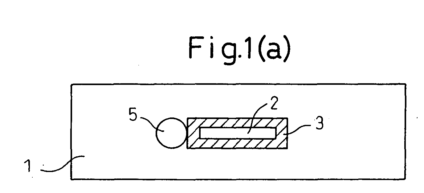
- Figs. 1(a) and 1(b) are views illustrating an embodiment of the circularly welded joint according to the present invention.
- a steel plate 1 that receives the main stress and a steel plate 2 that does not receive the main stress are perpendicularly together, and are welded together at the surrounding circularly welded portion 3.
- the steel 1 plate is used as a strengthening member for the welded structure while the steel plate 2 is used for a purpose other than the strengthening member.
- the steel plate 1 of the side which receives main stress is at least the one that suppresses the propagation of cracks due to fatigue. This is because, cracks due to fatigue through the repetition of stress' cause a problem in this member.
- the steel plate that suppresses the propagation of cracks due to fatigue stands for the above-mentioned SUF steel having a very fine microstructure in the surface layer and a steel plate that suppresses the propagation of cracks due to fatigue by controlling the two-phase zone rolling and the microstructure.
- cracks become stagnant due to the hard phase formed in the soft phase, and start branching so as to detour around the hard phase.
- the closure effect is promoted to suppress the cracks, and the rate of propagation of cracks becomes 1/10 to 1/4 that of the general steel plates.
- the steel plate for suppressing the propagation of cracks due to fatigue is the one that has the compressive residual stress in the surface layer of the steel plate.
- the tensile residual stress due to the heat input at the time of welding can be relaxed.
- the stress can be transformed into the compressive residual stress over a range of from the surface of the steel plate deep into the plate in the direction of thickness of the plate, and the fatigue strength can be improved to a remarkable degree.
- the range is confined to be not larger than 5 mm. This is because, the stress concentrates in this range, and striking the range in excess of 5 mm does not work to relax the concentration of stress.
- impacted traces there can be formed impacted traces, at a depth of about several hundreds of microns, having excellent surface smoothness of impacted portions by using a power source of 500 W to 1 KW, by generating ultrasonic oscillation of 20 Hz to 60 Hz by using a transducer, and by amplifying the oscillation through a wave guide to oscillate an ultrasonic oscillation terminal, which is a pin of a diameter of 2 mm to 6 mm, with an amplitude of 30 to 40 ⁇ m.
- Fig. 2 is a diagram illustrating a distribution of residual stress at a point A (where the ultrasonic impact is effected) in Fig. 1(b) in the direction of the plate thickness of the steel plate 1 of prior to effecting the circularly welding.
- the direction (+) represents the tensile residual stress and the direction (-) represents the compressive residual stress.
- the cooling water is sprayed onto the surface of the steel plate 1 to quickly cool it, whereby the compressive residual stress is generated in an amount of about 50% of the yield stress in the surface layer of the steel plate as shown in Fig. 2.
- Fig. 3 is a diagram illustrating a distribution of residual stress at the point A (where the ultrasonic impact is effected) in Fig. 1(b) in the direction of the plate thickness of the steel plate 1 after having effected the circularly welding.
- the direction (+) represents the tensile residual stress and the direction (-) represents the compressive residual stress.
- the tensile residual stress is generated to a degree of about 90% of the yield stress in the front and back surfaces of the steel plate.
- the concentration of stress is promoted at the welding end portion, and the fatigue strength decreases to a remarkable degree.
- Fig. 3 illustrates a case where the steel plate 1 is circularly welded from the front and back surfaces, and the distribution is symmetrical between the front surface and the back surface.
- Fig. 4 is a diagram illustrating a distribution of residual stress at the point A in Fig. 1(b) in the direction of the plate thickness of the steel plate 1 after having effected the ultrasonic impact.
- the direction (+) represents the tensile residual stress
- the direction (-) represents the compressive residual stress
- the residual stress in the direction of main stress is the compressive residual stress over a range of t 0 ⁇ t/8 in the direction of plate thickness from the circularly welded surface of the steel plate. Namely, the concentration of stress at the welding end is relaxed to a large extent making it possible to greatly increase the fatigue strength.
- the distribution of residual stress (dotted line) is such that the range of the compressive residual stress is in the quite surface layer in the direction of plate thickness, exhibiting a small effect for relaxing the concentration of stress at the end portion and, hence, exhibiting a small effect for increasing the fatigue strength.
- welded structures such as buildings, ships, bridges, construction machinery and off-shore structures by using the circularly welded joints featuring excellent fatigue strength of the present invention, it is made possible to provide welded structures featuring excellent fatigue strength.
- Figs. 2 and 3 show chemical composition (mass%) and production processes of the steel plate used for the Example.
- the steels A to F are ordinary finished steels which do not suppress the propagation of cracks due to fatigue
- the steels G to L are propagation suppress steels for suppressing the propagation of cracks due to fatigue used in the present invention.
- Fig. 4 shows the results of impacting a range within 5 mm from the end of the circularly welded joints of the steels A to L by using an ultrasonic oscillation terminal.
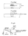
- Figs. 5(a) and 5(b) are diagrams illustrating the circularly welded joint used for the embodiment.
- the distance to of the compressive residual stress zone from the surface layer shown in Fig. 6 was measured by an X-ray sin 2 ⁇ method.
- the residual stress in the surface layer was measured, the residual stress was measured after the grinding while maintaining a gap of 0.5 mm in the direction of plate thickness to find a distance to a position where the residual stress becomes zero from the surface layer.
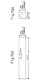
- Figs. 7(a) and 7(b) are views illustrating a test piece used for the propagation testing of cracks due to fatigue.
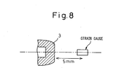
- a strain gauge was fixed at a place 5 mm away from the end portion, and the time until the output of the strain gauge has dropped by 5% was regarded to be the occurring life.
- Nos. 1, 3, 5, 7, 9 and 11 are Comparative Examples in which the ordinary finished steels were not subjected to the ultrasonic impact treatment. Therefore, the residual stress at the end portion became the tensile residual stress, and the breaking life, which is the sum of the occurring life until the cracks occur due to fatigue and the propagation life, became the shortest.
- Nos. 2, 4, 6, 8, 10 and 12 are Comparative Examples in which the ordinary finished steels were subjected to the ultrasonic impact treatment.
- the residual stress at the end portion became the compressive residual stress.
- t the thickness of the steel plate
- the compressive residual stress exists only within a range of not larger than t/15 in the direction of the plate thickness from the surface layer. Therefore, the breaking life, which is the sum of the occurring life until the cracks occur due to fatigue, and the propagation life were about twice as great as those when the ultrasonic impact treatment was not effected.
- Nos. 13, 15, 17, 19, 21 and 23 are Comparative Examples in which the steels suppressing the propagation of cracks due to fatigue were not subjected to the ultrasonic impact treatment. Therefore, the residual stress at the end portion became the tensile residual stress. Due to the effect for suppressing the propagation of cracks due to fatigue, however, the breaking life, which is the sum of the occurring life until the cracks occur due to fatigue, and the propagation life were about twice as great as those of the ordinary finished steel.
- Nos. 14, 16, 18, 20, 22 and 24 are Examples of the present invention in which the steels suppressing the propagation of cracks due to fatigue were subjected to the ultrasonic impact treatment.
- the residual stress at the end portion became the compressive residual stress.
- the thickness of the steel plate is denoted by t
- the compressive residual stress exists over a range of not smaller than t/10 or not smaller than 3 mm in the direction of the plate thickness from the surface layer. Therefore, the breaking life, which is the sum of the occurring life until the cracks occur due to fatigue and the propagation life, became not smaller than three times as great as those of the case of when the ultrasonic impact treatment was not effected.
- a circularly welded joint featuring excellent fatigue strength obtained by welding the ends of two pieces of steel plates perpendicularly together and used for the welded structures such as buildings, ships, bridges, construction machinery and off-shore structures, a method of producing the circularly welded joints and a welded structure using the circularly welded joints.
- the end portions of the circularly welded joint, using a steel plate which suppresses the propagation of cracks due to fatigue are subjected to the ultrasonic impact treatment to increase the breaking life of the welded joint to not smaller than three times as long as that of the conventional welded joints and, hence, to improve the reliability of the welded structures against the breakdown by fatigue, which are industrially very useful effects.
Landscapes
- Engineering & Computer Science (AREA)
- Mechanical Engineering (AREA)
- Physics & Mathematics (AREA)
- Plasma & Fusion (AREA)
- Heat Treatment Of Steel (AREA)
- Butt Welding And Welding Of Specific Article (AREA)
Abstract
Description


Claims (4)
- A circularly welded joint, featuring excellent fatigue strength properties, obtained by welding the ends of two pieces of steel plates perpendicularly together, wherein between the two pieces of said steel plates, at least the steel plate on the side on which the main stress is exerted is the one that suppresses the propagation of cracks due to fatigue and, when the thickness of said steel plate is denoted by t, the residual stress in the direction of main stress is the compressive residual stress over a range of not smaller than t/10 or not smaller than 3 mm in the direction of plate thickness from the circularly welded surface of said steel plate.
- A circularly welded joint featuring excellent fatigue strength according to claim 1, wherein said steel plate that suppresses the propagation of cracks due to fatigue is one that has the compressive residual stress in the surface layer of said steel plate.
- A method of producing a circularly welded joint featuring excellent fatigue strength of claim 1 or 2, wherein a range within 5 mm from the end portion of said circularly welded joint is impacted with an ultrasonic oscillation terminal.
- A welded structure, featuring excellent fatigue strength, using the circularly welded joint of claim 1 or 2.
Applications Claiming Priority (3)
| Application Number | Priority Date | Filing Date | Title |
|---|---|---|---|
| JP2002294397 | 2002-10-08 | ||
| JP2002294397A JP4537649B2 (en) | 2002-10-08 | 2002-10-08 | Rotating welded joint, manufacturing method of Rotated welded joint, and welded structure |
| PCT/JP2003/012916 WO2004033144A1 (en) | 2002-10-08 | 2003-10-08 | Boxing joint with excellent fatigue strength, method of manufacturing the boxing joint, and welded structure |
Publications (3)
| Publication Number | Publication Date |
|---|---|
| EP1579945A1 true EP1579945A1 (en) | 2005-09-28 |
| EP1579945A4 EP1579945A4 (en) | 2010-05-05 |
| EP1579945B1 EP1579945B1 (en) | 2012-12-12 |
Family
ID=32089174
Family Applications (1)
| Application Number | Title | Priority Date | Filing Date |
|---|---|---|---|
| EP03754044A Expired - Lifetime EP1579945B1 (en) | 2002-10-08 | 2003-10-08 | Method of manufacturing a boxing joint with high fatigue strength |
Country Status (8)
| Country | Link |
|---|---|
| US (1) | US7695825B2 (en) |
| EP (1) | EP1579945B1 (en) |
| JP (1) | JP4537649B2 (en) |
| KR (1) | KR100606312B1 (en) |
| CN (1) | CN100446910C (en) |
| AU (1) | AU2003272950A1 (en) |
| ES (1) | ES2400851T3 (en) |
| WO (1) | WO2004033144A1 (en) |
Families Citing this family (13)
| Publication number | Priority date | Publication date | Assignee | Title |
|---|---|---|---|---|
| JP4555794B2 (en) * | 2005-04-08 | 2010-10-06 | 新日本製鐵株式会社 | Metal parts or metal structures excellent in fatigue crack initiation / propagation prevention characteristics and methods for producing the same |
| JP5052918B2 (en) * | 2007-03-07 | 2012-10-17 | 新日本製鐵株式会社 | Welded joint, welded structure excellent in crack initiation propagation characteristics, and method for improving crack initiation propagation characteristics |
| JP5251486B2 (en) * | 2008-12-22 | 2013-07-31 | 新日鐵住金株式会社 | Machining method using ultrasonic impact treatment |
| ES2542743T3 (en) * | 2009-12-04 | 2015-08-11 | Nippon Steel & Sumitomo Metal Corporation | Welded structure with a butt welded joint and method for manufacturing |
| RU2469109C2 (en) * | 2010-11-10 | 2012-12-10 | Федеральное государственное бюджетное образовательное учреждение высшего профессионального образования "Национальный исследовательский ядерный университет "МИФИ" (НИЯУ МИФИ) | Ultrasonic device to process welded joints of metals of austenitic class in process of automatic welding |
| KR101594913B1 (en) * | 2011-03-28 | 2016-02-17 | 제이에프이 스틸 가부시키가이샤 | Thick steel sheet having superior fatigue resistance properties in sheet thickness direction, method for producing same, and fillet welded joint using said thick steel sheet |
| JP5972480B2 (en) * | 2012-11-29 | 2016-08-17 | 北京理工大学 | Standard value residual stress calibration sample and its manufacturing and storage method |
| CN103434205B (en) * | 2013-07-18 | 2016-02-24 | 浙江中隧桥波形钢腹板有限公司 | Corrugated sheet steel and plain plate welded unit and manufacturing process |
| JP6662399B2 (en) * | 2017-03-31 | 2020-03-11 | Jfeスチール株式会社 | Turning welding joint and turning welding method excellent in fatigue strength |
| CN109765271B (en) * | 2018-12-30 | 2021-09-07 | 河海大学 | Apparatus and method for judging hammer closure of metal fatigue cracks |
| JP6696604B1 (en) | 2019-03-08 | 2020-05-20 | Jfeスチール株式会社 | Needle peening method |
| CN110280884B (en) * | 2019-07-29 | 2020-12-22 | 吉林大学 | Ultrasonic impact toughening joint with groove added with alloy powder |
| KR102211568B1 (en) | 2019-11-20 | 2021-02-03 | 한국생산기술연구원 | Apparatus and method for controlling residual stress in welded joint |
Family Cites Families (31)
| Publication number | Priority date | Publication date | Assignee | Title |
|---|---|---|---|---|
| US3274033A (en) * | 1963-08-12 | 1966-09-20 | Branson Instr | Ultrasonics |
| DE2415764A1 (en) * | 1974-04-01 | 1975-10-09 | Kraftwerk Union Ag | HEAT EXCHANGER |
| JPS5524717A (en) * | 1978-08-08 | 1980-02-22 | Toshiba Corp | Method of preventing stress corrosion cracking |
| JP3002229B2 (en) * | 1990-05-14 | 2000-01-24 | 川崎製鉄株式会社 | Method for improving the fatigue strength of welded joints |
| JPH04113187U (en) * | 1991-03-15 | 1992-10-02 | 三菱重工業株式会社 | Welded structure with fatigue fracture prevention function |
| JPH06262385A (en) * | 1993-03-16 | 1994-09-20 | Nippon Steel Corp | Improving method for fatigue strength of end part of weld by local quenching |
| JP2991586B2 (en) * | 1993-03-22 | 1999-12-20 | 新日本製鐵株式会社 | Steel sheet excellent in fatigue propagation resistance and manufacturing method thereof |
| US5634988A (en) * | 1993-03-25 | 1997-06-03 | Nippon Steel Corporation | High tensile steel having excellent fatigue strength at its weld and weldability and process for producing the same |
| JP3037855B2 (en) | 1993-09-13 | 2000-05-08 | 新日本製鐵株式会社 | Steel sheet with good fatigue crack propagation resistance and method for producing the same |
| JPH07204844A (en) * | 1994-01-14 | 1995-08-08 | Ishikawajima Harima Heavy Ind Co Ltd | Welding method for pipe branch and cooling device |
| JPH08118012A (en) * | 1994-10-31 | 1996-05-14 | Mitsubishi Heavy Ind Ltd | Method for preventing generation of fatigue crack |
| JP3489243B2 (en) | 1995-02-16 | 2004-01-19 | 住友金属工業株式会社 | Ferritic bainite duplex stainless steel |
| JPH08333632A (en) | 1995-06-06 | 1996-12-17 | Ishikawajima Harima Heavy Ind Co Ltd | Method of introducing compressive residual stress to metal surface |
| JPH10122768A (en) * | 1996-10-17 | 1998-05-15 | Honda Motor Co Ltd | Heat exchanger |
| DE69724569T2 (en) * | 1996-12-27 | 2004-07-08 | Kawasaki Steel Corp., Kobe | welding processes |
| JP3434434B2 (en) | 1997-06-10 | 2003-08-11 | 新日本製鐵株式会社 | Steel material excellent in fatigue crack propagation characteristics and method of manufacturing the same |
| US6171415B1 (en) | 1998-09-03 | 2001-01-09 | Uit, Llc | Ultrasonic impact methods for treatment of welded structures |
| JP2000158127A (en) * | 1998-11-30 | 2000-06-13 | Nippon Steel Corp | Welding method for steel with excellent arrestability |
| JP3298544B2 (en) * | 1999-03-29 | 2002-07-02 | 住友金属工業株式会社 | Steel plate with fatigue crack growth control effect |
| KR100520371B1 (en) * | 1999-12-17 | 2005-10-11 | 제이에프이 스틸 가부시키가이샤 | Welding material and method for producing welding joint by using the same and welding joint by the method |
| US6467321B2 (en) * | 2000-05-30 | 2002-10-22 | Integrity Testing Laboratory, Inc. | Device for ultrasonic peening of metals |
| JP2002096192A (en) * | 2000-09-21 | 2002-04-02 | Nippon Steel Corp | High fatigue strength welded joint |
| JP2002129281A (en) | 2000-10-23 | 2002-05-09 | Nippon Steel Corp | High-strength steel for welded structure having excellent weld fatigue properties and method of manufacturing the same |
| CN1102478C (en) * | 2000-10-27 | 2003-03-05 | 重庆大学 | Crack welding and repairing process for ferrous metal parts |
| CA2450369A1 (en) * | 2001-06-12 | 2002-12-19 | Leonid Mikhaylovich Lobanov | Method for processing welded metalwork joints by high-frequency hummering |
| JP4537621B2 (en) | 2001-06-19 | 2010-09-01 | 新日本製鐵株式会社 | Steel tube column base and method for strengthening steel tube column base |
| JP4537622B2 (en) | 2001-06-19 | 2010-09-01 | 新日本製鐵株式会社 | Steel tube column base and method for strengthening steel tube column base |
| JP4394860B2 (en) * | 2002-04-08 | 2010-01-06 | 新日本製鐵株式会社 | Welding method using ultra low temperature transformation melt, high fatigue strength joint and ultra low temperature transformation melt |
| US20050252888A1 (en) * | 2002-09-09 | 2005-11-17 | Akihiko Ohta | Welding method using welding material of low transformation temperature |
| US20070000968A1 (en) * | 2003-10-08 | 2007-01-04 | Tadashi Ishikawa | Weld structure having excellent resistance brittle crack propagation resistance and method of welding the weld structure |
| US7399371B2 (en) * | 2004-04-16 | 2008-07-15 | Nippon Steel Corporation | Treatment method for improving fatigue life and long-life metal material treated by using same treatment |
-
2002
- 2002-10-08 JP JP2002294397A patent/JP4537649B2/en not_active Expired - Fee Related
-
2003
- 2003-10-08 AU AU2003272950A patent/AU2003272950A1/en not_active Abandoned
- 2003-10-08 KR KR1020057005948A patent/KR100606312B1/en not_active Expired - Fee Related
- 2003-10-08 CN CNB2003801011111A patent/CN100446910C/en not_active Expired - Fee Related
- 2003-10-08 ES ES03754044T patent/ES2400851T3/en not_active Expired - Lifetime
- 2003-10-08 US US10/530,948 patent/US7695825B2/en not_active Expired - Fee Related
- 2003-10-08 WO PCT/JP2003/012916 patent/WO2004033144A1/en not_active Ceased
- 2003-10-08 EP EP03754044A patent/EP1579945B1/en not_active Expired - Lifetime
Also Published As
| Publication number | Publication date |
|---|---|
| KR100606312B1 (en) | 2006-07-28 |
| AU2003272950A1 (en) | 2004-05-04 |
| KR20050054997A (en) | 2005-06-10 |
| WO2004033144A1 (en) | 2004-04-22 |
| ES2400851T3 (en) | 2013-04-12 |
| JP4537649B2 (en) | 2010-09-01 |
| US20070134059A1 (en) | 2007-06-14 |
| EP1579945B1 (en) | 2012-12-12 |
| EP1579945A4 (en) | 2010-05-05 |
| CN100446910C (en) | 2008-12-31 |
| CN1703300A (en) | 2005-11-30 |
| US7695825B2 (en) | 2010-04-13 |
| JP2004130316A (en) | 2004-04-30 |
Similar Documents
| Publication | Publication Date | Title |
|---|---|---|
| EP1579945A1 (en) | Boxing joint with excellent fatigue strength, method of manufacturing the boxing joint, and welded structure | |
| EP1559796A1 (en) | Method of increasing toughness of heat-affected part of steel product welded joint | |
| JPWO2009104798A1 (en) | Welded joint with excellent fatigue resistance and method for producing the same | |
| US12234535B2 (en) | Weathering steel for solid-state welding, weathering steel material for solid-state welding, solid-state welded structure and solid-state welding method | |
| Ying et al. | Correction of buckling distortion by ultrasonic shot peening treatment for 5A06 aluminum alloy welded structure | |
| Tuz | Evaluation of microstructure and selected mechanical properties of laser beam welded S690QL high-strength steel | |
| Komerla et al. | The effect of beam oscillations on the microstructure and mechanical properties of electron beam welded steel joints | |
| JP2004130313A (en) | Method of improving fatigue strength of lap fillet welded joint | |
| JP2006320960A (en) | Metal parts or metal structures having excellent fatigue crack initiation / propagation suppression characteristics and methods for producing the same | |
| JP5251486B2 (en) | Machining method using ultrasonic impact treatment | |
| JP4392337B2 (en) | Processing method and structure using ultrasonic striking device | |
| Kim et al. | Effect of laser beam wobbling on the overlap joint strength of hot-press-forming steel over 2.0 GPa tensile strength | |
| JP2004169340A (en) | Reinforcement method of girder structure | |
| JP5599653B2 (en) | Welded joint | |
| JP4767885B2 (en) | Welded joint, welded structure excellent in brittle crack propagation stopping characteristics, and method for improving brittle crack propagation stopping characteristics | |
| JP3840172B2 (en) | UOE steel pipe manufacturing method with excellent HAZ toughness | |
| JP6314670B2 (en) | Structure with excellent fatigue characteristics | |
| Gai et al. | Ductile—brittle transition of steel electron beam weld metal in small punch test | |
| Illés et al. | Post-treatment of welding joints of high strength steels II.: Improving residual stress condition–Overview | |
| JP3843059B2 (en) | Manufacturing method of UOE steel pipe excellent in seam weld strength characteristics and internal pressure fatigue characteristics | |
| Rhee et al. | Fatigue behavior characterization of laser-welded cold rolled sheet metal (SPCEN) | |
| Wang et al. | Effect of ultra-sonic peening on laser-arc hybrid welded NV E690 steel | |
| JP3900490B2 (en) | Fatigue reinforcement method for girders with flange gussets | |
| El-Deen et al. | Optimization of electron beam welding parameters of dissimilar joint of aisi 304 stainless steel and aisi 1020 low carbon steEL | |
| JP2024146759A (en) | Methods for improving fatigue strength of welds |
Legal Events
| Date | Code | Title | Description |
|---|---|---|---|
| PUAI | Public reference made under article 153(3) epc to a published international application that has entered the european phase |
Free format text: ORIGINAL CODE: 0009012 |
|
| 17P | Request for examination filed |
Effective date: 20050413 |
|
| AK | Designated contracting states |
Kind code of ref document: A1 Designated state(s): AT BE BG CH CY CZ DE DK EE ES FI FR GB GR HU IE IT LI LU MC NL PT RO SE SI SK TR |
|
| AX | Request for extension of the european patent |
Extension state: AL LT LV MK |
|
| DAX | Request for extension of the european patent (deleted) | ||
| A4 | Supplementary search report drawn up and despatched |
Effective date: 20100408 |
|
| RIC1 | Information provided on ipc code assigned before grant |
Ipc: B23K 9/02 20060101ALI20100331BHEP Ipc: C21D 7/02 20060101ALI20100331BHEP Ipc: B23K 31/00 20060101AFI20040426BHEP Ipc: C21D 9/50 20060101ALI20100331BHEP Ipc: B23K 9/235 20060101ALI20100331BHEP |
|
| 17Q | First examination report despatched |
Effective date: 20100723 |
|
| GRAC | Information related to communication of intention to grant a patent modified |
Free format text: ORIGINAL CODE: EPIDOSCIGR1 |
|
| GRAP | Despatch of communication of intention to grant a patent |
Free format text: ORIGINAL CODE: EPIDOSNIGR1 |
|
| RIC1 | Information provided on ipc code assigned before grant |
Ipc: C21D 9/50 20060101ALI20120322BHEP Ipc: B23K 31/00 20060101AFI20120322BHEP Ipc: B23K 9/02 20060101ALI20120322BHEP Ipc: B23K 9/235 20060101ALI20120322BHEP Ipc: C21D 7/02 20060101ALI20120322BHEP |
|
| RTI1 | Title (correction) |
Free format text: METHOD OF MANUFACTURING A BOXING JOINT WITH HIGH FATIGUE STRENGTH |
|
| GRAS | Grant fee paid |
Free format text: ORIGINAL CODE: EPIDOSNIGR3 |
|
| RIN1 | Information on inventor provided before grant (corrected) |
Inventor name: NAKASHIMA, KIYOTAKA Inventor name: ISHIKAWA, TADASHI |
|
| GRAA | (expected) grant |
Free format text: ORIGINAL CODE: 0009210 |
|
| AK | Designated contracting states |
Kind code of ref document: B1 Designated state(s): AT BE BG CH CY CZ DE DK EE ES FI FR GB GR HU IE IT LI LU MC NL PT RO SE SI SK TR |
|
| REG | Reference to a national code |
Ref country code: GB Ref legal event code: FG4D |
|
| REG | Reference to a national code |
Ref country code: CH Ref legal event code: EP |
|
| REG | Reference to a national code |
Ref country code: AT Ref legal event code: REF Ref document number: 588090 Country of ref document: AT Kind code of ref document: T Effective date: 20121215 |
|
| REG | Reference to a national code |
Ref country code: IE Ref legal event code: FG4D |
|
| RAP2 | Party data changed (patent owner data changed or rights of a patent transferred) |
Owner name: NIPPON STEEL & SUMITOMO METAL CORPORATION |
|
| REG | Reference to a national code |
Ref country code: DE Ref legal event code: R082 Ref document number: 60342849 Country of ref document: DE Representative=s name: VOSSIUS & PARTNER, DE Ref country code: DE Ref legal event code: R082 Ref document number: 60342849 Country of ref document: DE Representative=s name: VOSSIUS & PARTNER PATENTANWAELTE RECHTSANWAELT, DE |
|
| REG | Reference to a national code |
Ref country code: DE Ref legal event code: R096 Ref document number: 60342849 Country of ref document: DE Effective date: 20130207 |
|
| REG | Reference to a national code |
Ref country code: NL Ref legal event code: T3 |
|
| REG | Reference to a national code |
Ref country code: SE Ref legal event code: TRGR |
|
| REG | Reference to a national code |
Ref country code: ES Ref legal event code: FG2A Ref document number: 2400851 Country of ref document: ES Kind code of ref document: T3 Effective date: 20130412 |
|
| REG | Reference to a national code |
Ref country code: AT Ref legal event code: MK05 Ref document number: 588090 Country of ref document: AT Kind code of ref document: T Effective date: 20121212 |
|
| PG25 | Lapsed in a contracting state [announced via postgrant information from national office to epo] |
Ref country code: GR Free format text: LAPSE BECAUSE OF FAILURE TO SUBMIT A TRANSLATION OF THE DESCRIPTION OR TO PAY THE FEE WITHIN THE PRESCRIBED TIME-LIMIT Effective date: 20130313 Ref country code: SI Free format text: LAPSE BECAUSE OF FAILURE TO SUBMIT A TRANSLATION OF THE DESCRIPTION OR TO PAY THE FEE WITHIN THE PRESCRIBED TIME-LIMIT Effective date: 20121212 |
|
| PG25 | Lapsed in a contracting state [announced via postgrant information from national office to epo] |
Ref country code: EE Free format text: LAPSE BECAUSE OF FAILURE TO SUBMIT A TRANSLATION OF THE DESCRIPTION OR TO PAY THE FEE WITHIN THE PRESCRIBED TIME-LIMIT Effective date: 20121212 Ref country code: AT Free format text: LAPSE BECAUSE OF FAILURE TO SUBMIT A TRANSLATION OF THE DESCRIPTION OR TO PAY THE FEE WITHIN THE PRESCRIBED TIME-LIMIT Effective date: 20121212 Ref country code: CY Free format text: LAPSE BECAUSE OF FAILURE TO SUBMIT A TRANSLATION OF THE DESCRIPTION OR TO PAY THE FEE WITHIN THE PRESCRIBED TIME-LIMIT Effective date: 20121212 Ref country code: SK Free format text: LAPSE BECAUSE OF FAILURE TO SUBMIT A TRANSLATION OF THE DESCRIPTION OR TO PAY THE FEE WITHIN THE PRESCRIBED TIME-LIMIT Effective date: 20121212 Ref country code: BG Free format text: LAPSE BECAUSE OF FAILURE TO SUBMIT A TRANSLATION OF THE DESCRIPTION OR TO PAY THE FEE WITHIN THE PRESCRIBED TIME-LIMIT Effective date: 20130312 |
|
| PG25 | Lapsed in a contracting state [announced via postgrant information from national office to epo] |
Ref country code: PT Free format text: LAPSE BECAUSE OF FAILURE TO SUBMIT A TRANSLATION OF THE DESCRIPTION OR TO PAY THE FEE WITHIN THE PRESCRIBED TIME-LIMIT Effective date: 20130412 Ref country code: RO Free format text: LAPSE BECAUSE OF FAILURE TO SUBMIT A TRANSLATION OF THE DESCRIPTION OR TO PAY THE FEE WITHIN THE PRESCRIBED TIME-LIMIT Effective date: 20121212 |
|
| PLBE | No opposition filed within time limit |
Free format text: ORIGINAL CODE: 0009261 |
|
| STAA | Information on the status of an ep patent application or granted ep patent |
Free format text: STATUS: NO OPPOSITION FILED WITHIN TIME LIMIT |
|
| PG25 | Lapsed in a contracting state [announced via postgrant information from national office to epo] |
Ref country code: DK Free format text: LAPSE BECAUSE OF FAILURE TO SUBMIT A TRANSLATION OF THE DESCRIPTION OR TO PAY THE FEE WITHIN THE PRESCRIBED TIME-LIMIT Effective date: 20121212 |
|
| 26N | No opposition filed |
Effective date: 20130913 |
|
| REG | Reference to a national code |
Ref country code: DE Ref legal event code: R097 Ref document number: 60342849 Country of ref document: DE Effective date: 20130913 |
|
| PG25 | Lapsed in a contracting state [announced via postgrant information from national office to epo] |
Ref country code: MC Free format text: LAPSE BECAUSE OF FAILURE TO SUBMIT A TRANSLATION OF THE DESCRIPTION OR TO PAY THE FEE WITHIN THE PRESCRIBED TIME-LIMIT Effective date: 20121212 |
|
| REG | Reference to a national code |
Ref country code: CH Ref legal event code: PL |
|
| REG | Reference to a national code |
Ref country code: IE Ref legal event code: MM4A |
|
| PG25 | Lapsed in a contracting state [announced via postgrant information from national office to epo] |
Ref country code: LI Free format text: LAPSE BECAUSE OF NON-PAYMENT OF DUE FEES Effective date: 20131031 Ref country code: CH Free format text: LAPSE BECAUSE OF NON-PAYMENT OF DUE FEES Effective date: 20131031 |
|
| PG25 | Lapsed in a contracting state [announced via postgrant information from national office to epo] |
Ref country code: IE Free format text: LAPSE BECAUSE OF NON-PAYMENT OF DUE FEES Effective date: 20131008 |
|
| PG25 | Lapsed in a contracting state [announced via postgrant information from national office to epo] |
Ref country code: TR Free format text: LAPSE BECAUSE OF FAILURE TO SUBMIT A TRANSLATION OF THE DESCRIPTION OR TO PAY THE FEE WITHIN THE PRESCRIBED TIME-LIMIT Effective date: 20121212 |
|
| PG25 | Lapsed in a contracting state [announced via postgrant information from national office to epo] |
Ref country code: HU Free format text: LAPSE BECAUSE OF FAILURE TO SUBMIT A TRANSLATION OF THE DESCRIPTION OR TO PAY THE FEE WITHIN THE PRESCRIBED TIME-LIMIT; INVALID AB INITIO Effective date: 20031008 Ref country code: LU Free format text: LAPSE BECAUSE OF NON-PAYMENT OF DUE FEES Effective date: 20131008 |
|
| REG | Reference to a national code |
Ref country code: FR Ref legal event code: PLFP Year of fee payment: 14 |
|
| REG | Reference to a national code |
Ref country code: FR Ref legal event code: PLFP Year of fee payment: 15 |
|
| REG | Reference to a national code |
Ref country code: FR Ref legal event code: PLFP Year of fee payment: 16 |
|
| REG | Reference to a national code |
Ref country code: DE Ref legal event code: R082 Ref document number: 60342849 Country of ref document: DE Representative=s name: VOSSIUS & PARTNER PATENTANWAELTE RECHTSANWAELT, DE Ref country code: DE Ref legal event code: R081 Ref document number: 60342849 Country of ref document: DE Owner name: NIPPON STEEL CORPORATION, JP Free format text: FORMER OWNER: NIPPON STEEL & SUMITOMO METAL CORPORATION, TOKYO, JP |
|
| PGFP | Annual fee paid to national office [announced via postgrant information from national office to epo] |
Ref country code: FR Payment date: 20190913 Year of fee payment: 17 Ref country code: NL Payment date: 20190912 Year of fee payment: 17 Ref country code: CZ Payment date: 20190923 Year of fee payment: 17 |
|
| PGFP | Annual fee paid to national office [announced via postgrant information from national office to epo] |
Ref country code: BE Payment date: 20190917 Year of fee payment: 17 |
|
| PGFP | Annual fee paid to national office [announced via postgrant information from national office to epo] |
Ref country code: DE Payment date: 20190924 Year of fee payment: 17 Ref country code: FI Payment date: 20191009 Year of fee payment: 17 Ref country code: SE Payment date: 20191010 Year of fee payment: 17 |
|
| PGFP | Annual fee paid to national office [announced via postgrant information from national office to epo] |
Ref country code: ES Payment date: 20191104 Year of fee payment: 17 Ref country code: IT Payment date: 20191009 Year of fee payment: 17 |
|
| PGFP | Annual fee paid to national office [announced via postgrant information from national office to epo] |
Ref country code: GB Payment date: 20191003 Year of fee payment: 17 |
|
| PG25 | Lapsed in a contracting state [announced via postgrant information from national office to epo] |
Ref country code: CZ Free format text: LAPSE BECAUSE OF NON-PAYMENT OF DUE FEES Effective date: 20201008 |
|
| REG | Reference to a national code |
Ref country code: DE Ref legal event code: R119 Ref document number: 60342849 Country of ref document: DE |
|
| REG | Reference to a national code |
Ref country code: FI Ref legal event code: MAE |
|
| REG | Reference to a national code |
Ref country code: SE Ref legal event code: EUG |
|
| REG | Reference to a national code |
Ref country code: NL Ref legal event code: MM Effective date: 20201101 |
|
| GBPC | Gb: european patent ceased through non-payment of renewal fee |
Effective date: 20201008 |
|
| REG | Reference to a national code |
Ref country code: BE Ref legal event code: MM Effective date: 20201031 |
|
| PG25 | Lapsed in a contracting state [announced via postgrant information from national office to epo] |
Ref country code: DE Free format text: LAPSE BECAUSE OF NON-PAYMENT OF DUE FEES Effective date: 20210501 Ref country code: NL Free format text: LAPSE BECAUSE OF NON-PAYMENT OF DUE FEES Effective date: 20201101 Ref country code: FI Free format text: LAPSE BECAUSE OF NON-PAYMENT OF DUE FEES Effective date: 20201008 Ref country code: FR Free format text: LAPSE BECAUSE OF NON-PAYMENT OF DUE FEES Effective date: 20201031 |
|
| PG25 | Lapsed in a contracting state [announced via postgrant information from national office to epo] |
Ref country code: SE Free format text: LAPSE BECAUSE OF NON-PAYMENT OF DUE FEES Effective date: 20201009 Ref country code: GB Free format text: LAPSE BECAUSE OF NON-PAYMENT OF DUE FEES Effective date: 20201008 Ref country code: BE Free format text: LAPSE BECAUSE OF NON-PAYMENT OF DUE FEES Effective date: 20201031 |
|
| PG25 | Lapsed in a contracting state [announced via postgrant information from national office to epo] |
Ref country code: IT Free format text: LAPSE BECAUSE OF NON-PAYMENT OF DUE FEES Effective date: 20201008 |
|
| REG | Reference to a national code |
Ref country code: ES Ref legal event code: FD2A Effective date: 20220120 |
|
| PG25 | Lapsed in a contracting state [announced via postgrant information from national office to epo] |
Ref country code: ES Free format text: LAPSE BECAUSE OF NON-PAYMENT OF DUE FEES Effective date: 20201009 |