EP1577182B1 - Scheibenwischervorrichtung - Google Patents
Scheibenwischervorrichtung Download PDFInfo
- Publication number
- EP1577182B1 EP1577182B1 EP03777238.1A EP03777238A EP1577182B1 EP 1577182 B1 EP1577182 B1 EP 1577182B1 EP 03777238 A EP03777238 A EP 03777238A EP 1577182 B1 EP1577182 B1 EP 1577182B1
- Authority
- EP
- European Patent Office
- Prior art keywords
- wiper
- wiper arm
- vis
- blade
- rotary shaft
- Prior art date
- Legal status (The legal status is an assumption and is not a legal conclusion. Google has not performed a legal analysis and makes no representation as to the accuracy of the status listed.)
- Expired - Lifetime
Links
- 238000001514 detection method Methods 0.000 claims description 42
- 230000005389 magnetism Effects 0.000 claims description 25
- 230000007246 mechanism Effects 0.000 claims description 24
- 230000009467 reduction Effects 0.000 claims description 21
- 230000002093 peripheral effect Effects 0.000 claims description 5
- 238000000034 method Methods 0.000 description 12
- 230000008859 change Effects 0.000 description 7
- 229910052760 oxygen Inorganic materials 0.000 description 6
- 230000002441 reversible effect Effects 0.000 description 5
- 238000004519 manufacturing process Methods 0.000 description 4
- 230000002159 abnormal effect Effects 0.000 description 3
- 230000007704 transition Effects 0.000 description 2
- RYGMFSIKBFXOCR-UHFFFAOYSA-N Copper Chemical compound [Cu] RYGMFSIKBFXOCR-UHFFFAOYSA-N 0.000 description 1
- 230000005415 magnetization Effects 0.000 description 1
- 230000008569 process Effects 0.000 description 1
- 239000011347 resin Substances 0.000 description 1
- 229920005989 resin Polymers 0.000 description 1
- 230000000087 stabilizing effect Effects 0.000 description 1
- 229910052717 sulfur Inorganic materials 0.000 description 1
Images


Classifications
-
- B—PERFORMING OPERATIONS; TRANSPORTING
- B60—VEHICLES IN GENERAL
- B60S—SERVICING, CLEANING, REPAIRING, SUPPORTING, LIFTING, OR MANOEUVRING OF VEHICLES, NOT OTHERWISE PROVIDED FOR
- B60S1/00—Cleaning of vehicles
- B60S1/02—Cleaning windscreens, windows or optical devices
- B60S1/04—Wipers or the like, e.g. scrapers
- B60S1/06—Wipers or the like, e.g. scrapers characterised by the drive
- B60S1/08—Wipers or the like, e.g. scrapers characterised by the drive electrically driven
-
- H—ELECTRICITY
- H02—GENERATION; CONVERSION OR DISTRIBUTION OF ELECTRIC POWER
- H02K—DYNAMO-ELECTRIC MACHINES
- H02K11/00—Structural association of dynamo-electric machines with electric components or with devices for shielding, monitoring or protection
- H02K11/20—Structural association of dynamo-electric machines with electric components or with devices for shielding, monitoring or protection for measuring, monitoring, testing, protecting or switching
- H02K11/21—Devices for sensing speed or position, or actuated thereby
- H02K11/215—Magnetic effect devices, e.g. Hall-effect or magneto-resistive elements
-
- H—ELECTRICITY
- H02—GENERATION; CONVERSION OR DISTRIBUTION OF ELECTRIC POWER
- H02K—DYNAMO-ELECTRIC MACHINES
- H02K11/00—Structural association of dynamo-electric machines with electric components or with devices for shielding, monitoring or protection
- H02K11/30—Structural association with control circuits or drive circuits
- H02K11/38—Control circuits or drive circuits associated with geared commutator motors of the worm-and-wheel type
-
- H—ELECTRICITY
- H02—GENERATION; CONVERSION OR DISTRIBUTION OF ELECTRIC POWER
- H02K—DYNAMO-ELECTRIC MACHINES
- H02K7/00—Arrangements for handling mechanical energy structurally associated with dynamo-electric machines, e.g. structural association with mechanical driving motors or auxiliary dynamo-electric machines
- H02K7/10—Structural association with clutches, brakes, gears, pulleys or mechanical starters
- H02K7/116—Structural association with clutches, brakes, gears, pulleys or mechanical starters with gears
- H02K7/1163—Structural association with clutches, brakes, gears, pulleys or mechanical starters with gears where at least two gears have non-parallel axes without having orbital motion
- H02K7/1166—Structural association with clutches, brakes, gears, pulleys or mechanical starters with gears where at least two gears have non-parallel axes without having orbital motion comprising worm and worm-wheel
Definitions
- the wiper arm position is detected by adding/subtracting the number of pulses generated by a pulse generator whose operation is interlocked with the rotary motion of the motor.
- a multi-polar magnet is fitted to the rotary shaft of the motor and a sensor typically comprising Hall ICs is arranged vis-à-vis the magnet in order to detect the polar change due to the rotation of the rotary shaft and to output a pulse signal.
- the pulse count is reset at a point (origin position) that operates as reference position for the rotary position of the output shaft of the motor unit in order to prevent discrepancies of pulses.
- a magnet is also fitted to the output shaft and a corresponding sensor is arranged in such a way that the sensor outputs a reference signal when a magnetic pole passes by a predetermined position.
- An object of the present invention is to provide a wiper device that can reliably detect the wiper arm position with a small number of sensors.
- the predetermined position of the output shaft is either side of rotating direction relative to the reference position as the polarity of the first magnetic pole and that of the second magnetic pole are determined by means of the first and second magnetism detection elements.
- the motor abnormally stops because of a power shut down or some other reason, it is possible to force it to start in such a way that the predetermined position of the output shaft thereof comes to be located vis-à-vis the reference position with the smallest rotary angle.
- the wiper arm passes the reference position or arrives at the lower limit position thereafter in its one way movement without fail and the count value of the pulse signal is reset to the reference value or the predetermined value, whichever appropriate, so that it is possible to accurately grasp the position of the wiper arm.
- Two permanent magnets 12, 13 are arranged on the inner peripheral surface of the motor housing 10 with the opposite magnetic poles thereof facing each other to produce a magnetic field in the inside of the motor housing 10.
- An armature 14 is arranged within the magnetic field in the inside of the motor housing 10.
- the rotary shaft 15 of the armature 14 is rotatably supported by self-aligning type bearings 16, 17.
- the bearings 16, 17 are arranged respectively on the bottom 10b of the motor housing 10 and in the bearing section 11a.
- the armature 14 has an armature core 18 that is provided with a plurality of slots.
- a copper wire is wound around the armature core 18 through the slots to form an armature coil 19.
- a commutator 29 is fixed to the shaft at the left side of the armature core 18 in FIG. 2 .
- the commutator 20 includes a trunk section 20a, which is made of resin and rigidly fitted to the rotary shaft 15, and a plurality of commutator segments 20b, which is radially arranged on the periphery of the trunk section and insulated each other. The commutator segments 20b are connected to the armature coil 19.
- the rotary shaft 15 projects into the inside of the gear chamber 11b.
- the front end section 15a of the rotary shaft 15 is located near the wall surface 26 of the gear chamber 11b that is located away from the motor main body 8.
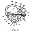
- two worms 27, 28 that are threaded in opposite directions are formed in the outer peripheral surface of the rotary shaft 15 at a position located in the inside of the gear chamber 11b.
- Two worm wheels 29, 30 are arranged in the inside of the gear chamber 11b so as to be engaged with the worms 27, 28 respectively.
- the worms 27, 28 and the worm wheels 29, 30 constitute a worm gear 31.
- Pinion gears 32, 33 are arranged so as to be respectively coaxial with the worm wheels 29, 30.
- the pinion gears 32, 33 are engaged with a drive gear 35 that is a rotary body integral with the output shaft 34 of the speed reduction mechanism 9.
- a drive gear 35 that is a rotary body integral with the output shaft 34 of the speed reduction mechanism 9.
- the output shafts 34 of the motors 7a, 7b are mechanically linked to the respective wiper shafts 4a, 4b.
- the wiper shafts 4a, 4b rotate integrally with the respective output shafts 34.
- the worms 27, 28 are subjected to thrust that acts in the axial direction of the rotary shaft 15 because of the provision of the worm wheels 29, 30. Since the worms 27, 28 are threaded in opposite directions, the thrust is made to act in two opposite directions. As a result, any movement of the rotary shaft 15 in the directions of the thrust is suppressed and hence it is not necessary to arrange any thrust bearing and the like for the rotary shaft 15.
- a printed circuit board 36 is fitted to the wall surface 26 of the casing 11 and arranged so as to extend perpendicularly relative to the rotary shaft 15.
- a connection terminal 40 located in the communication section 11c is fitted to the printed circuit board 36. Power is supplied and detection signals are transmitted from a control section (not shown) by way of the connection terminal 40.
- a Hall IC is a sensor that transforms a change in the magnetic field into an electric current and emits a pulse signal.
- the object of detection of a Hall IC needs to be a magnet.
- a ring-shaped sensor magnet 41 is attached to the bottom of the drive gear 35 along the outer peripheral surface thereof as object of detection for the absolute position detecting Hall ICs 37a, 37b.
- the sensor magnet 41 is adapted to rotate integrally with the drive gear 35 and magnetized to show two poles in the sense of rotation thereof.
- a multi-polar magnet 42 (to be referred to simply as magnet 42 hereinafter) is fitted to the front end 15a of the rotary shaft 15 as object of detection for the relative position detecting Hall ICs 38, 39.
- the magnet 42 is adapted to rotate integrally with the rotary shaft 15 and magnetized to show six poles in the sense of rotation thereof.
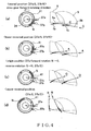
- FIG. 4 is a schematic illustration of the positional relationship between the Hall ICs 37a, 37b and the sensor magnet 41.
- one of the poles (S-pole in the illustrations) of the sensor magnet 41 is made to show a larger angle of magnetization than the other pole (N-pole in the illustrations).
- the drive gear 35 rotates, the magnetic poles that passes in front of the Hall ICs 37a, 37b change accordingly.
- the positions of the wiper arms 1a, 1b can be recognized by means of the combination of the changes.
- the Hall ICs 38, 39 are fitted to the surface of the printed circuit board 36 at respective positions located vis-à-vis the magnet 42 with their phases shifted by 90° in the sense of rotation of the magnet 42.
- the Hall ICs 38, 39 output respective pulses for six cycle periods.
- the pulses are transmitted toward a control section (not shown) by way of the connection terminal 40 so that it is possible to detect the rotary angle of the rotary shaft 15 by counting the pulses. Since the phases of the Hall ICs 38, 39 are shifted by 90° from each other, the sequence of appearance of the pulses transmitted from the Hall ICs 38, 39 varies depending on the sense of rotation of the rotary shaft 15.
- the Hall ICs 37a, 37b respectively face the S-pole and the N-pole of the sensor magnet 41. Then, the detection signal of the Hall ICs 37a, 37b will be "37a : S, 37b : N" as shown in FIG. 4 (a) .
- the Hall IC 37a also comes to face the N-pole of the of the sensor magnet 41. Then, the detection signal of the Hall ICs 37a, 37b will be "37a : N, 37b : N" as shown in FIG. 4(b) .
- the combinations of magnetic poles as detected by the Hall ICs 37a, 37b at the above described control points differ from each other and hence it is possible to know the current positions of the wiper arms 1a, 1b approximately by identifying the current combinations of magnetic poles. Additionally, it is possible to detect the moving direction of the wiper arms 1a, 1b by catching the change of the magnetic pole or poles when the wiper arms 1a, 1b passes the origin positions. In short, the two Hall ICs 37a, 37b can recognize the wiper arms 1a, 1b at four positions. The positions of the magnetic poles including the S-pole and the N-pole of the sensor magnet 41 may be switched.
- the signal from the Hall ICs 37a, 37b will be "37a : S, 37b : S". If, on the other hand, the signal from the Hall ICs 37a, 37b is other than the combination of "37a : S, 37b : S", the wiper arms 1a, 1b are positioned respectively at the side of the low reversal positions relative to the origin positions O.
- the wiper arms 1a, 1b respectively pass the origin positions O without fail if they are driven to move toward the sides of the lower reversal positions.
- the signal of the Hall ICs 37a, 37b is other than "37a : S, 37b : S”
- the wiper arms 1a, 1b respectively pass the origin positions O without fail if they are driven to move toward the sides of the upper reversal positions.
- the signal from the Hall IC 37a becomes to be S - N and the pulse count of the Hall ICs 38, 39 is reset.
- the pulse count is restarted for the movements of the wiper arms 1a, 1b toward the lower reversal positions A and, when a predetermined number of pulses are counted, the control section recognizes that the wiper arms 1a, 1b are at the respective lower reversal positions A. Accordingly, the motor starts rotating in the opposite direction once again and the wiper arms 1a, 1b start moving toward the upper reversal positions B.
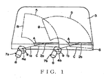
- the wiper arms 1a, 1b swing respectively between the lower reversal positions A and the upper reversal positions B for wiping operations by the wiper blades 2a, 2b.
- the control section drives the wiper arms 1a, 1b to move respectively from the lower reversal positions A to the storage sections 6.
- the pulse counting operation of the Hall ICs 38, 39 is continued during the above described movements and, when a predetermined number of pulses are counted, the control section recognizes that the wiper arms 1a, 1b arrive at the respective stored positions C and stops the supply of electric current to the brushes 22, 23.
- FIG. 6 is a schematic cross sectional view of a motor unit that is used for a wiper device to which a control method is applicable.
- the motor unit 101 of FIG. 6 is adapted to be used as drive source of a wiper device of an automobile.
- the wiper blade of the wiper device (to be referred to simply as blade hereinafter) gets to the upper and lower reversal positions, the sense of rotation of the motor unit 101 is switched.
- the motor unit 101 comprises a motor 102 and a gear box 103.
- the rotation of the rotary shaft 104 of the motor 102 is reduced in the gear box 103 and output by way of an output shaft 105.
- the rotary shaft 104 is rotatably borne by a yoke 106 showing a profile of a bottomed cylinder.
- An armature core 107 around which a coil is wound and a commutator 108 are fitted to the rotary shaft 104.
- a plurality of permanent magnets 109 are rigidly secured to the inner surface of the yoke 106.
- a feed brush 110 is held in contact with the commutator 108.
- the speed of the motor 102 (the number of revolutions per unit time) is controlled by way of the intensity of the electric current supplied to the brush 110.
- Case frame 111 of the gear box 103 is fitted to the peripheral edge of the open end of the yoke 106.
- FIG. 7 is a schematic illustration of the inside of the case frame 111 of the motor unit of FIG. 6 as viewed from above.
- FIG. 8 is a schematic illustration of the inside of the case frame 111 of the motor unit similar to FIG. 7 but without the gear in the gear box 103.
- the front end of the rotary shaft 104 of the motor unit that projects from the yoke 106 is contained in the case frame 111.
- Worms 112a, 112b are formed at the front end of the rotary shaft 104.
- the worms 112a, 112b are engaged respectively with worm gears 113a, 113b that are rotatably supported by the case frame 111.
- Small diameter first gears 114a, 114b are integrally and coaxially formed with the respective worm gears 113a, 113b.
- the first gears 114a, 114b are engaged with a large diameter second gear 115.
- An output shaft 105 is integrally fitted to the second gear 115 and rotatably borne by the case frame 111.
- the drive power of the motor 2 is transmitted to the output shaft 105 at a reduced rotary speed by way of the worms 112a, 112b, the worm gears 113a, 113b, the first gears 114a, 114b and the second gear 115.
- the link mechanism (not shown) of the wiper device is connected to the output shaft 105. As the electric motor 102 is driven to operate, the link member is by turn driven by way of the output shaft 105 and cooperates with the other link members in an interlocked manner to drive the wiper arm to move.
- Stoppers 121, 122 project from the bottom surface 111a of the case frame 111 for the purpose of restricting the rotary angle of the second gear 115.
- the second gear 115 is provided with a guide groove 123 that matches the stoppers 121, 122.
- FIG. 9 is a schematic illustration of the configuration of the second gear 115.
- the guide groove 123 is formed to extend along the circumference of the second gear 115 and illustrated as a hatched area in FIG. 9 .
- the stoppers 121, 122 are contained in the guide groove 123.
- the opposite ends of the guide groove 123 are walls that operate as respective rotation restricting sections 124, 125.
- the blade As the second gear 115 rotates and the rotation restricting section 124 hits the stopper 121, the blade is mechanically restricted so that it cannot move downward any further. Similarly, as the rotation restricting section 125 hits the stopper 122, the blade is mechanically restricted so that it cannot move upward any further.
- a multi-polar magnet 116 (to be referred to simply as magnet 116 hereinafter) is fitted to the rotary shaft 104 and Hall ICs 117 are arranged in the case frame 111 so as to face the outer periphery of the magnet 116.
- FIG. 10 is a schematic illustration of the relationship between the magnet 116 and the Hall ICs 117 and the output signal (motor pulse) of the Hall ICs 117.
- the two Hall ICs 117 (117A, 117B) are arranged at positions that form 90° relative to the center of the rotary shaft 104. Since the magnet 116 is magnetized to show six poles, as the rotary shaft 104 rotates and makes a full turn, the Hall ICs 117 output respective pulses for six cycle periods.
- the number of revolutions per unit time of the rotary shaft 104 and the moving speed of the wiper blade show a correlation that is determined as a function of the reduction ratio and the working ratio of the link so that it is possible to computationally determine the moving speed of the blade on the basis of the number of revolutions per unit time of the rotary shaft 104.
- a ring magnet 118 (to be referred to simply as magnet 118 hereinafter) is fitted to the bottom surface of the second gear 115 for the purpose of detecting the absolute positions of the blade.
- a printed circuit board 119 is fitted to the case frame 111 and a Hall IC 120 is arranged on the printed circuit board 119 and vis-à-vis the magnet 118.
- the crank arm is fitted to the second gear 115 so as to rotate by about 180° when the blade is driven to reciprocate for a wiping operation.
- the Hall IC 120 squarely faces the magnet 118 and an origin position reset signal is output.
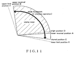
- FIG. 11 is a schematic illustration of the moving range of the blade.
- the blade reciprocates between the upper and lower reversal positions A and B, or within the wiping range hatched in FIG. 11 .
- the blade moves from the lower reversal position A to the upper reversal position B when the motor is driven to turn forward, whereas it moves from the upper reversal position B to the lower reversal position A when the motor is driven to turn backward.
- the blade is moved to a stored position C that is located below the lower reversal position A and stored in the storage section.
- the storage section is arranged in the inside of the bonnet (not shown) of the body of the automobile.
- the origin position reset signal is used as a reference signal that indicates the absolute position of the blade.
- an origin position reset signal is obtained, it is judged that the blade just passes the origin position O shown in FIG. 11 .
- the motor pulses from the Hall IC 117 are used as signal indicating the relative position of the blade.
- the output motor pulses are proportional to the rotary angle of the rotary shaft 4 and the pulse count value (accumulated number) thereof corresponds to the angle by which the rotary shaft 4 rotates.
- a lower limit position X and an upper limit position Y are formed respectively at the outside of the stored position C and at the outside of the upper reversal position B by the stoppers 121, 122 and the guide groove 123 as limits of mechanical motion.
- the lower limit position X and the upper limit position Y define mechanical limits and hence located at respective positions that are always separated from the origin position O by predetermined distances (angles). In other words, when the blade gets to the lower limit position X or the upper limit position Y, the pulse count value from the origin position O always shows a constant value. Therefore, it is possible to use the lower limit position X and/or the upper limit position Y as position for resetting the pulse count value just like the origin position O.
- the wiper device of this embodiment firstly drives the blade to move backwardly toward the origin position O in order to grasp the current position of the blade. If the blade is driven to move backwardly when it is positioned between B and O, it passes the origin position thereafter without fail.
- the wiper device of this embodiment may be so arranged that the pulse count value is appropriately corrected by using the lower limit position X so as not to produce any discrepancies due to a repeated reciprocating motion when the blade is positioned between the lower reversal position A and the stored position C.
- Either of two techniques may be used to correct the pulse count value for this purpose. With the first technique, the blade is moved to the lower limit position X each time it is operated to move and the pulse count value is reset to the count value of the lower limit position X.
- the pulse count value is reset when large discrepancies seem to arise in the pulse.
- the blade when an angular deviation occurs to the blade toward the stored position C, the blade eventually gets to the lower limit position X as the deviation increases and the pulse count value is automatically corrected there.
- the blade when an angular deviation occurs to the blade toward the lower reversal position A, the blade eventually gets to the origin position O as the deviation increases and the pulse count value is automatically reset there.
- a resetting operation at the origin position O is disadvantageous to the wiper device from the control point of view because the blade is driven to move beyond the lower reverse position A.
- the wiper device of this embodiment when the blade abnormally stops because of a power shut down or some other reason, it is possible to reset the pulse count value, utilizing the origin position O or the lower limit position X, when the blade is started to move once again from the abnormally stopped state. Therefore, the wiper device of this embodiment is free from a situation where it cannot recognize the current position of the blade when the blade is started to move once again from an abnormally stopped state and an overrun takes place at the upper reversal position B and hence the blade is started to move once again very smoothly. Additionally, the pulse discrepancies that take place when the blade is moving between the lower reversal position A and the stored position C can be corrected accurately to make it possible to drive the blade to reciprocate very smoothly. Only a single sensor, or a Hall IC 120, is required for the above-described operation of correctly driving the blade in the wiper device of this embodiment. Thus, it is possible to reduce the number of sensors and the manufacturing cost of the product.
- an electric motor according to the invention is applied to a wiper device of an automobile
- the present invention is by no means limited thereto and it can find applications in the field of other car accessories such as power windows and also in the field of home electric appliances.
- the two wiper arms are driven to move respectively by means of the two different motors 7a, 7b in the above described first embodiment, it is possible to drive the two wiper arms 1a, 1b to move by means of a single electric motor and a link mechanism.
- the present invention is applied to a parallel wiping type wiper device in each of the above described embodiments, the present invention can also be applied to an opposite type wiper device.
- the magnetic poles (N, S) of the ring-shaped sensor magnet 41 of the first embodiment may be inversely arranged. Then, the magnetic poles detected by the Hall ICs 37a, 37b are opposite to those illustrated in FIGS. 4 and 5 .
- the setting of mechanically restricting positions is not limited to the use of stoppers 121, 122 and a guide groove 123 as described above.
- the rotary angle of the second gear 115 may be restricted by the engagement of a pin that is arranged to project from the case frame 111 and a groove that is formed to contain the pin in the second gear 115.
- a rotary restricting section 126 for restricting swing angle is provided in the link mechanism, and accordingly, a mechanical limit position may be set.
- a wiper device comprises a sensor magnet having a first magnetic pole and a second magnetic pole. Both first and second magnetism detection elements are located vis-à-vis the second magnetic pole (e.g., the S-pole) when a wiper arm is at the side of an upper reversal position relative to a reference position, and at least either the first magnetism detection element or the second magnetism detection element is located vis-à-vis the first magnetic pole (e.g., the N-pole) when the wiper arm is at the side of a lower reversal position relative to the reference position.
- the second magnetic pole e.g., the S-pole
- the wiper arm is driven by an electric motor and the wiper arm position is detected by means of the count value of the pulse signal output as a result of the rotary motion of the motor to control the operation of the wiper arm
- the passage through the reference position of the wiper arm is detected by a sensor.
- the arrival to the lower limit position gives rise to mechanical restrictions and the count value of the pulse signal at that time shows a predetermined known value.
- the position of the wiper arm at the time of restarting can be grasped by means of a single sensor that is arranged at the reference position. Then, it is possible to reduce the number of sensors to a minimally necessary number and hence the cost of manufacturing the device.
Landscapes
- Engineering & Computer Science (AREA)
- Power Engineering (AREA)
- Microelectronics & Electronic Packaging (AREA)
- Mechanical Engineering (AREA)
- Connection Of Motors, Electrical Generators, Mechanical Devices, And The Like (AREA)
Claims (7)
- Scheibenwischereinrichtung, die eingerichtet ist, um durch einen elektrischen Motor mit einem Untersetzungsmechanismus (7a, 7b), der einen Motorhauptkörper (8), der eine Drehachse (15) aufweist, und einen Untersetzungsmechanismus (9), zum Reduzieren der Drehzahl der Drehachse (15) und zum Übertragen der Umdrehungen der Drehachse (15) zu einer Antriebswelle (34) beinhaltet, angetrieben zu werden, mit:einem Scheibenwischerarm (1a, 1b), der mit der Antriebswelle (34) verbunden ist und eingerichtet ist, um sich beim einen Scheibenwischvorgang zwischen einer oberen Umkehrposition und einer unteren Umkehrposition hin und her zu bewegen;gekennzeichnet durchein erstes Magnetismusdetektionselement (37a, 37b), das so angeordnet ist, dass es gegenüber einer vorbestimmten Position der Antriebswelle angeordnet ist, wenn der Scheibenwischerarm an einer Referenzposition befindet;ein zweites Magnetismusdetektionselement (38, 39), das an einer Position, die von dem ersten Magnetismusdetektionselement (37a, 37b) um einen vorbestimmten Winkel beabstandet ist, angeordnet ist;einen Sensormagnet (41), der an der Antriebswelle (34) angeordnet ist und einen ersten magnetischen Pol und einen zweiten magnetischen Pol, die in einer Umfangsrichtung angeordnet sind und die unterschiedliche Polaritäten aufzeigen, aufweist, wobei sowohl die ersten als auch die zweiten Magnetismusdetektionselemente (37a, 37b, 38, 39) gegenüber dem zweiten magnetischen Pol angeordnet sind, wenn sich der Scheibenwischerarm (1a, 1b) relativ zu der Referenzposition an der Seite der oberen Umkehrposition befindet, wobei zumindest entweder das erste Magnetismusdetektionselement (37a, 37b) oder das zweite Magnetismusdetektionselement (38, 39) gegenüber dem ersten magnetischen Pol angeordnet sind, wenn sich der Scheibenwischerarm (1a, 1b) relativ zu der Referenzposition an der Seite der unteren Umkehrposition befindet; undeinen Sensor (40) zum Detektieren des Drehwinkels der Drehachse (15), wobei der Sensor (40) den Drehwinkel der Drehachse zum Zeitpunkt, zu dem der Scheibenwischerarm (1a, 1b) in der Referenzposition positioniert ist, zu detektieren beginnt.
- Einrichtung gemäß Anspruch 1, bei der
das erste Magnetismusdetektionselement (37a, 37b) gegenüber der Grenze des ersten magnetischen Pols und des zweiten magnetischen Pols angeordnet ist, wenn der Scheibenwischerarm (1a, 1b) die Referenzposition durchläuft. - Einrichtung gemäß Anspruch 1 oder 2, bei der
sowohl das erste Magnetismusdetektionselement (37a, 37b) als auch das zweite Magnetismusdetektionselement (38, 39) gegenüber dem ersten magnetischen Pol angeordnet sind, wenn sich der Scheibenwischerarm (1a, 1b) an der unteren Umkehrposition befindet. - Einrichtung gemäß einem der Ansprüche 1 bis 3, bei der
eine Scheibenwischerarmruheposition unter der unteren Umkehrposition angeordnet ist und das erste Magnetismusdetektionselement (37a, 37b) gegenüber dem ersten magnetischen Pol angeordnet ist und das zweite Magnetismusdetektionselement (38, 39) gegenüber dem zweiten magnetischen Pol angeordnet ist, wenn sich der Scheibenwischerarm (1a, 1b) an der Ruheposition befindet. - Einrichtung gemäß einem der Ansprüche 1 bis 4, bei der,
wenn der Scheibenwischerarm (1a, 1b) während des Betriebs zwischen der oberen Umkehrposition und der unteren Umkehrposition anhält, er immer so neu gestartet wird, dass er sich zum Zeitpunkt des Neustarts zu der Referenzposition hin bewegt. - Einrichtung gemäß Anspruch 4, bei der,
wenn der Scheibenwischerarm (1a, 1b) in einer anderen Position als der Ruheposition anhält, der Scheibenwischerarm (1a, 1b) immer so neu gestartet wird, dass er sich zum Zeitpunkt des Neustarts zu der Referenzposition hin bewegt. - Einrichtung gemäß Anspruch 1, bei der die Einrichtung einen elektrischen Motor mit einem Untersetzungsmechanismus aufweist, mit: einem Motorhauptkörper (8), der eine Drehachse (15) aufweist, und einem Geschwindigkeitsreduktionsmechanismus (9) zum Reduzieren der Drehzahl der Drehachse (15) und der die Umdrehungen zu einer Antriebswelle (34) überträgt.
Applications Claiming Priority (5)
| Application Number | Priority Date | Filing Date | Title |
|---|---|---|---|
| JP2002363041A JP4298991B2 (ja) | 2002-12-13 | 2002-12-13 | ワイパ装置の制御方法及びワイパ装置並びに減速機構付きモータ |
| JP2002363041 | 2002-12-13 | ||
| JP2003341493 | 2003-09-30 | ||
| JP2003341493A JP4410524B2 (ja) | 2003-09-30 | 2003-09-30 | ワイパ装置制御方法 |
| PCT/JP2003/015519 WO2004054856A1 (ja) | 2002-12-13 | 2003-12-04 | ワイパ装置制御方法及びワイパ装置並びに減速機構付きモータ |
Publications (3)
| Publication Number | Publication Date |
|---|---|
| EP1577182A1 EP1577182A1 (de) | 2005-09-21 |
| EP1577182A4 EP1577182A4 (de) | 2010-03-10 |
| EP1577182B1 true EP1577182B1 (de) | 2013-06-05 |
Family
ID=32599258
Family Applications (1)
| Application Number | Title | Priority Date | Filing Date |
|---|---|---|---|
| EP03777238.1A Expired - Lifetime EP1577182B1 (de) | 2002-12-13 | 2003-12-04 | Scheibenwischervorrichtung |
Country Status (3)
| Country | Link |
|---|---|
| US (1) | US7586275B2 (de) |
| EP (1) | EP1577182B1 (de) |
| WO (1) | WO2004054856A1 (de) |
Families Citing this family (26)
| Publication number | Priority date | Publication date | Assignee | Title |
|---|---|---|---|---|
| EP1663740A4 (de) * | 2003-09-15 | 2010-04-14 | Magna Closures Inc | Umkehrmotor-windschutzscheibenwischersystem |
| US7503310B2 (en) * | 2005-03-21 | 2009-03-17 | Continental Automotive Canada, Inc. | Packaging arrangement for an increment position sensor |
| JPWO2007052503A1 (ja) | 2005-10-31 | 2009-04-30 | 株式会社ミツバ | ワイパ制御方法及びワイパ制御システム |
| DE102006045928A1 (de) * | 2006-09-28 | 2008-04-03 | Robert Bosch Gmbh | Anschlusssystem mit außenliegender Leitungsführung an Wischermotorgehäusen |
| DE102006060621A1 (de) * | 2006-12-21 | 2008-06-26 | Robert Bosch Gmbh | Elektrische Antriebsvorrichtung mit einer elektronischen Steuerungseinheit |
| DE102008024356A1 (de) * | 2008-05-20 | 2009-11-26 | Valeo Systèmes d'Essuyage | Elektromotorischer Hilfsantrieb, insbesondere Wischermotor |
| JP5186465B2 (ja) | 2008-12-09 | 2013-04-17 | アスモ株式会社 | ワイパ装置及びワイパ制御方法 |
| DE102010002793A1 (de) * | 2010-03-11 | 2011-09-15 | Robert Bosch Gmbh | Antriebseinrichtung mit einem elektrischen Antriebsmotor und einem Getriebe |
| FR2959711B1 (fr) * | 2010-05-06 | 2012-07-20 | Ece | Circuit et procede de commande pour moteur electrique, notamment d'entrainement d'essuie-glace |
| US9031390B2 (en) * | 2012-03-26 | 2015-05-12 | Asmo Co., Ltd. | Wiper device |
| JP5840048B2 (ja) * | 2012-03-26 | 2016-01-06 | アスモ株式会社 | ワイパ装置 |
| BR112014025606B1 (pt) * | 2012-04-16 | 2018-03-13 | Mitsuba Corporation | Aparelho Limpador |
| JP5996486B2 (ja) * | 2012-08-06 | 2016-09-21 | アスモ株式会社 | 車両用ワイパ装置 |
| CN103401492A (zh) * | 2013-08-09 | 2013-11-20 | 张岳峰 | 电子式无触点单向旋转智能雨刮器电机控制电路工作原理 |
| KR101490952B1 (ko) * | 2013-12-23 | 2015-02-09 | 현대자동차 주식회사 | 회전체의 위치를 파악하는 장치 및 이를 이용한 와이퍼 작동 장치 |
| KR102441844B1 (ko) * | 2015-02-04 | 2022-09-08 | 삼성전자주식회사 | 회전체를 제어하기 위한 방법 및 그 전자 장치 |
| JP6411916B2 (ja) | 2015-02-26 | 2018-10-24 | ラピスセミコンダクタ株式会社 | 半導体装置、ワイパシステム、及び移動体制御方法 |
| KR101559117B1 (ko) * | 2015-05-21 | 2015-10-08 | 디와이오토 주식회사 | 차량용 와이퍼 모터 장치 |
| DE102015220277A1 (de) * | 2015-10-19 | 2017-04-20 | Robert Bosch Gmbh | Wischvorrichtung |
| JP6696190B2 (ja) * | 2016-02-01 | 2020-05-20 | 株式会社デンソー | ワイパ制御装置 |
| FR3055279A1 (fr) * | 2016-08-24 | 2018-03-02 | Valeo Systemes D'essuyage | Dispositif de motorisation d’essuie-glace et systeme d’essuyage |
| DE102019126430A1 (de) * | 2019-10-01 | 2021-04-01 | Infineon Technologies Ag | Erfassung eines Drehwinkels |
| US11613233B2 (en) * | 2021-01-25 | 2023-03-28 | Rosemount Aerospace Inc. | Windshield wiper system with an internal trigger |
| CN115675367A (zh) * | 2022-11-18 | 2023-02-03 | 湖南联诚轨道装备有限公司 | 一种轨道交通电动刮雨器系统 |
| CN116279855B (zh) * | 2023-02-14 | 2026-03-10 | 曼德电子电器有限公司 | 电动尾翼位置控制方法、装置及存储介质和汽车 |
| KR102869938B1 (ko) * | 2024-08-19 | 2025-10-13 | 디와이오토 주식회사 | 고장 대응용 이중 고정자 구조가 구비된 차량 와이퍼용 브러시리스 모터 장치 |
Family Cites Families (8)
| Publication number | Priority date | Publication date | Assignee | Title |
|---|---|---|---|---|
| DE19840895A1 (de) * | 1998-09-08 | 2000-03-16 | Bosch Gmbh Robert | Scheibenwischer-Antriebsvorrichtung |
| JP2000118360A (ja) * | 1998-10-09 | 2000-04-25 | Jidosha Denki Kogyo Co Ltd | ワイパモータの回転位置検出装置 |
| JP4005256B2 (ja) * | 1999-03-05 | 2007-11-07 | アスモ株式会社 | ワイパ制御装置 |
| JP2002002454A (ja) * | 2000-06-15 | 2002-01-09 | Niles Parts Co Ltd | ワイパー制御装置 |
| JP2002262515A (ja) | 2001-03-02 | 2002-09-13 | Mitsuba Corp | 減速機構付き電動モータ |
| JP2002264773A (ja) * | 2001-03-07 | 2002-09-18 | Mitsuba Corp | 対向払拭型ワイパ装置の制御方法 |
| JP2002264777A (ja) * | 2001-03-14 | 2002-09-18 | Mitsuba Corp | 対向払拭型ワイパ装置の制御方法 |
| JP2003054371A (ja) * | 2001-08-15 | 2003-02-26 | Jidosha Denki Kogyo Co Ltd | ワイパ制御装置 |
-
2003
- 2003-12-04 EP EP03777238.1A patent/EP1577182B1/de not_active Expired - Lifetime
- 2003-12-04 WO PCT/JP2003/015519 patent/WO2004054856A1/ja not_active Ceased
- 2003-12-04 US US10/537,803 patent/US7586275B2/en not_active Expired - Lifetime
Also Published As
| Publication number | Publication date |
|---|---|
| EP1577182A4 (de) | 2010-03-10 |
| WO2004054856A1 (ja) | 2004-07-01 |
| US7586275B2 (en) | 2009-09-08 |
| US20060113942A1 (en) | 2006-06-01 |
| EP1577182A1 (de) | 2005-09-21 |
Similar Documents
| Publication | Publication Date | Title |
|---|---|---|
| EP1577182B1 (de) | Scheibenwischervorrichtung | |
| JP4191509B2 (ja) | モータ制御方法及びモータ制御装置 | |
| JP6545169B2 (ja) | ブラシレスワイパモータおよびその組立方法 | |
| WO2015045003A1 (ja) | ブラシレスワイパモータ | |
| JP5129477B2 (ja) | ワイパモータ | |
| US9819288B2 (en) | Apparatus and method for detecting and preventing movement of a motor in a device of system | |
| CN100540367C (zh) | 刮水器装置控制方法 | |
| JP5634328B2 (ja) | モータ制御装置及びモータ制御方法 | |
| JP4410524B2 (ja) | ワイパ装置制御方法 | |
| US8005590B2 (en) | Wiper control method and wiper control system | |
| JP2013223317A (ja) | ブラシレスワイパモータ | |
| JP4298991B2 (ja) | ワイパ装置の制御方法及びワイパ装置並びに減速機構付きモータ | |
| JP6286293B2 (ja) | ワイパ装置 | |
| JP4981420B2 (ja) | 減速機構付き電動モータ | |
| JP4615885B2 (ja) | モータ制御方法及びモータ制御装置 | |
| JP2004254455A (ja) | 減速機構付き電動モータ | |
| JP2011057174A (ja) | ワイパ制御装置 | |
| US8897970B2 (en) | Wiper control device and wiper control method | |
| JP2020131885A (ja) | ワイパ装置並びにワイパ制御装置及びワイパ制御方法 | |
| JP5138951B2 (ja) | モータ | |
| JP2004007931A (ja) | 減速機構付き電動モータ | |
| JP2003219673A (ja) | モータ制御装置 |
Legal Events
| Date | Code | Title | Description |
|---|---|---|---|
| PUAI | Public reference made under article 153(3) epc to a published international application that has entered the european phase |
Free format text: ORIGINAL CODE: 0009012 |
|
| 17P | Request for examination filed |
Effective date: 20050628 |
|
| AK | Designated contracting states |
Kind code of ref document: A1 Designated state(s): DE FR GB |
|
| RBV | Designated contracting states (corrected) |
Designated state(s): DE FR |
|
| A4 | Supplementary search report drawn up and despatched |
Effective date: 20100210 |
|
| 17Q | First examination report despatched |
Effective date: 20101109 |
|
| GRAP | Despatch of communication of intention to grant a patent |
Free format text: ORIGINAL CODE: EPIDOSNIGR1 |
|
| GRAS | Grant fee paid |
Free format text: ORIGINAL CODE: EPIDOSNIGR3 |
|
| GRAA | (expected) grant |
Free format text: ORIGINAL CODE: 0009210 |
|
| AK | Designated contracting states |
Kind code of ref document: B1 Designated state(s): DE FR |
|
| REG | Reference to a national code |
Ref country code: DE Ref legal event code: R096 Ref document number: 60344233 Country of ref document: DE Effective date: 20130801 |
|
| PLBE | No opposition filed within time limit |
Free format text: ORIGINAL CODE: 0009261 |
|
| STAA | Information on the status of an ep patent application or granted ep patent |
Free format text: STATUS: NO OPPOSITION FILED WITHIN TIME LIMIT |
|
| 26N | No opposition filed |
Effective date: 20140306 |
|
| REG | Reference to a national code |
Ref country code: DE Ref legal event code: R097 Ref document number: 60344233 Country of ref document: DE Effective date: 20140306 |
|
| REG | Reference to a national code |
Ref country code: FR Ref legal event code: PLFP Year of fee payment: 13 |
|
| REG | Reference to a national code |
Ref country code: FR Ref legal event code: PLFP Year of fee payment: 14 |
|
| REG | Reference to a national code |
Ref country code: FR Ref legal event code: PLFP Year of fee payment: 15 |
|
| PGFP | Annual fee paid to national office [announced via postgrant information from national office to epo] |
Ref country code: DE Payment date: 20191119 Year of fee payment: 17 |
|
| PGFP | Annual fee paid to national office [announced via postgrant information from national office to epo] |
Ref country code: FR Payment date: 20191115 Year of fee payment: 17 |
|
| REG | Reference to a national code |
Ref country code: DE Ref legal event code: R119 Ref document number: 60344233 Country of ref document: DE |
|
| PG25 | Lapsed in a contracting state [announced via postgrant information from national office to epo] |
Ref country code: FR Free format text: LAPSE BECAUSE OF NON-PAYMENT OF DUE FEES Effective date: 20201231 |
|
| PG25 | Lapsed in a contracting state [announced via postgrant information from national office to epo] |
Ref country code: DE Free format text: LAPSE BECAUSE OF NON-PAYMENT OF DUE FEES Effective date: 20210701 |