EP1576864B1 - Trennplatte zum herstellen von leiterplattenkomponenten - Google Patents
Trennplatte zum herstellen von leiterplattenkomponenten Download PDFInfo
- Publication number
- EP1576864B1 EP1576864B1 EP03779556A EP03779556A EP1576864B1 EP 1576864 B1 EP1576864 B1 EP 1576864B1 EP 03779556 A EP03779556 A EP 03779556A EP 03779556 A EP03779556 A EP 03779556A EP 1576864 B1 EP1576864 B1 EP 1576864B1
- Authority
- EP
- European Patent Office
- Prior art keywords
- separator plate
- core layer
- layers
- aluminum
- plate according
- Prior art date
- Legal status (The legal status is an assumption and is not a legal conclusion. Google has not performed a legal analysis and makes no representation as to the accuracy of the status listed.)
- Expired - Lifetime
Links
- 238000004519 manufacturing process Methods 0.000 title claims abstract description 12
- 239000010410 layer Substances 0.000 claims abstract description 54
- 229910052751 metal Inorganic materials 0.000 claims abstract description 40
- 239000002184 metal Substances 0.000 claims abstract description 40
- 239000012792 core layer Substances 0.000 claims abstract description 23
- 238000003825 pressing Methods 0.000 claims abstract description 14
- 238000000576 coating method Methods 0.000 claims abstract description 7
- 239000011248 coating agent Substances 0.000 claims abstract description 5
- 229910052782 aluminium Inorganic materials 0.000 claims description 29
- XAGFODPZIPBFFR-UHFFFAOYSA-N aluminium Chemical compound [Al] XAGFODPZIPBFFR-UHFFFAOYSA-N 0.000 claims description 29
- RYGMFSIKBFXOCR-UHFFFAOYSA-N Copper Chemical compound [Cu] RYGMFSIKBFXOCR-UHFFFAOYSA-N 0.000 claims description 25
- 229910052802 copper Inorganic materials 0.000 claims description 13
- 239000010949 copper Substances 0.000 claims description 13
- 229910000831 Steel Inorganic materials 0.000 claims description 10
- 239000010959 steel Substances 0.000 claims description 10
- PXHVJJICTQNCMI-UHFFFAOYSA-N Nickel Chemical compound [Ni] PXHVJJICTQNCMI-UHFFFAOYSA-N 0.000 claims description 6
- 238000005253 cladding Methods 0.000 claims description 6
- 239000000314 lubricant Substances 0.000 claims description 5
- 229910000975 Carbon steel Inorganic materials 0.000 claims description 4
- 239000010962 carbon steel Substances 0.000 claims description 4
- 150000001336 alkenes Chemical class 0.000 claims description 3
- 229910052759 nickel Inorganic materials 0.000 claims description 3
- JRZJOMJEPLMPRA-UHFFFAOYSA-N olefin Natural products CCCCCCCC=C JRZJOMJEPLMPRA-UHFFFAOYSA-N 0.000 claims description 3
- 239000004411 aluminium Substances 0.000 claims description 2
- 238000007747 plating Methods 0.000 abstract description 5
- 238000005192 partition Methods 0.000 description 25
- 239000002131 composite material Substances 0.000 description 20
- 239000011889 copper foil Substances 0.000 description 13
- 239000010935 stainless steel Substances 0.000 description 13
- 229910001220 stainless steel Inorganic materials 0.000 description 13
- 229920005989 resin Polymers 0.000 description 8
- 239000011347 resin Substances 0.000 description 8
- 150000002739 metals Chemical class 0.000 description 7
- 230000006835 compression Effects 0.000 description 5
- 238000007906 compression Methods 0.000 description 5
- 239000004020 conductor Substances 0.000 description 5
- 238000009826 distribution Methods 0.000 description 5
- 239000000463 material Substances 0.000 description 5
- 229920003002 synthetic resin Polymers 0.000 description 5
- 239000000057 synthetic resin Substances 0.000 description 5
- 239000000853 adhesive Substances 0.000 description 4
- 230000001070 adhesive effect Effects 0.000 description 4
- 239000003822 epoxy resin Substances 0.000 description 4
- 229920000647 polyepoxide Polymers 0.000 description 4
- 229910000838 Al alloy Inorganic materials 0.000 description 3
- 239000004831 Hot glue Substances 0.000 description 3
- 238000005516 engineering process Methods 0.000 description 3
- 230000004927 fusion Effects 0.000 description 3
- 238000000926 separation method Methods 0.000 description 3
- 239000000758 substrate Substances 0.000 description 3
- NIXOWILDQLNWCW-UHFFFAOYSA-M Acrylate Chemical compound [O-]C(=O)C=C NIXOWILDQLNWCW-UHFFFAOYSA-M 0.000 description 2
- 230000008094 contradictory effect Effects 0.000 description 2
- 230000000694 effects Effects 0.000 description 2
- 239000007788 liquid Substances 0.000 description 2
- 239000002356 single layer Substances 0.000 description 2
- 239000007787 solid Substances 0.000 description 2
- 229910000851 Alloy steel Inorganic materials 0.000 description 1
- 239000004820 Pressure-sensitive adhesive Substances 0.000 description 1
- 239000012790 adhesive layer Substances 0.000 description 1
- AZDRQVAHHNSJOQ-UHFFFAOYSA-N alumane Chemical group [AlH3] AZDRQVAHHNSJOQ-UHFFFAOYSA-N 0.000 description 1
- -1 aluminum or copper Chemical class 0.000 description 1
- 230000000181 anti-adherent effect Effects 0.000 description 1
- 230000000712 assembly Effects 0.000 description 1
- 238000000429 assembly Methods 0.000 description 1
- 238000010276 construction Methods 0.000 description 1
- 150000001879 copper Chemical class 0.000 description 1
- 238000011161 development Methods 0.000 description 1
- 230000018109 developmental process Effects 0.000 description 1
- 230000005484 gravity Effects 0.000 description 1
- 230000012447 hatching Effects 0.000 description 1
Images
Classifications
-
- B—PERFORMING OPERATIONS; TRANSPORTING
- B32—LAYERED PRODUCTS
- B32B—LAYERED PRODUCTS, i.e. PRODUCTS BUILT-UP OF STRATA OF FLAT OR NON-FLAT, e.g. CELLULAR OR HONEYCOMB, FORM
- B32B15/00—Layered products comprising a layer of metal
-
- B—PERFORMING OPERATIONS; TRANSPORTING
- B32—LAYERED PRODUCTS
- B32B—LAYERED PRODUCTS, i.e. PRODUCTS BUILT-UP OF STRATA OF FLAT OR NON-FLAT, e.g. CELLULAR OR HONEYCOMB, FORM
- B32B37/00—Methods or apparatus for laminating, e.g. by curing or by ultrasonic bonding
- B32B37/14—Methods or apparatus for laminating, e.g. by curing or by ultrasonic bonding characterised by the properties of the layers
- B32B37/26—Methods or apparatus for laminating, e.g. by curing or by ultrasonic bonding characterised by the properties of the layers with at least one layer which influences the bonding during the lamination process, e.g. release layers or pressure equalising layers
-
- H—ELECTRICITY
- H05—ELECTRIC TECHNIQUES NOT OTHERWISE PROVIDED FOR
- H05K—PRINTED CIRCUITS; CASINGS OR CONSTRUCTIONAL DETAILS OF ELECTRIC APPARATUS; MANUFACTURE OF ASSEMBLAGES OF ELECTRICAL COMPONENTS
- H05K3/00—Apparatus or processes for manufacturing printed circuits
- H05K3/46—Manufacturing multilayer circuits
- H05K3/4611—Manufacturing multilayer circuits by laminating two or more circuit boards
-
- B—PERFORMING OPERATIONS; TRANSPORTING
- B32—LAYERED PRODUCTS
- B32B—LAYERED PRODUCTS, i.e. PRODUCTS BUILT-UP OF STRATA OF FLAT OR NON-FLAT, e.g. CELLULAR OR HONEYCOMB, FORM
- B32B37/00—Methods or apparatus for laminating, e.g. by curing or by ultrasonic bonding
- B32B37/14—Methods or apparatus for laminating, e.g. by curing or by ultrasonic bonding characterised by the properties of the layers
- B32B37/26—Methods or apparatus for laminating, e.g. by curing or by ultrasonic bonding characterised by the properties of the layers with at least one layer which influences the bonding during the lamination process, e.g. release layers or pressure equalising layers
- B32B2037/262—Partition plates or sheets for separating several laminates pressed simultaneously
-
- B—PERFORMING OPERATIONS; TRANSPORTING
- B32—LAYERED PRODUCTS
- B32B—LAYERED PRODUCTS, i.e. PRODUCTS BUILT-UP OF STRATA OF FLAT OR NON-FLAT, e.g. CELLULAR OR HONEYCOMB, FORM
- B32B2311/00—Metals, their alloys or their compounds
-
- B—PERFORMING OPERATIONS; TRANSPORTING
- B32—LAYERED PRODUCTS
- B32B—LAYERED PRODUCTS, i.e. PRODUCTS BUILT-UP OF STRATA OF FLAT OR NON-FLAT, e.g. CELLULAR OR HONEYCOMB, FORM
- B32B2457/00—Electrical equipment
- B32B2457/08—PCBs, i.e. printed circuit boards
-
- Y—GENERAL TAGGING OF NEW TECHNOLOGICAL DEVELOPMENTS; GENERAL TAGGING OF CROSS-SECTIONAL TECHNOLOGIES SPANNING OVER SEVERAL SECTIONS OF THE IPC; TECHNICAL SUBJECTS COVERED BY FORMER USPC CROSS-REFERENCE ART COLLECTIONS [XRACs] AND DIGESTS
- Y10—TECHNICAL SUBJECTS COVERED BY FORMER USPC
- Y10S—TECHNICAL SUBJECTS COVERED BY FORMER USPC CROSS-REFERENCE ART COLLECTIONS [XRACs] AND DIGESTS
- Y10S428/00—Stock material or miscellaneous articles
- Y10S428/901—Printed circuit
-
- Y—GENERAL TAGGING OF NEW TECHNOLOGICAL DEVELOPMENTS; GENERAL TAGGING OF CROSS-SECTIONAL TECHNOLOGIES SPANNING OVER SEVERAL SECTIONS OF THE IPC; TECHNICAL SUBJECTS COVERED BY FORMER USPC CROSS-REFERENCE ART COLLECTIONS [XRACs] AND DIGESTS
- Y10—TECHNICAL SUBJECTS COVERED BY FORMER USPC
- Y10T—TECHNICAL SUBJECTS COVERED BY FORMER US CLASSIFICATION
- Y10T428/00—Stock material or miscellaneous articles
- Y10T428/12—All metal or with adjacent metals
- Y10T428/12493—Composite; i.e., plural, adjacent, spatially distinct metal components [e.g., layers, joint, etc.]
- Y10T428/12736—Al-base component
- Y10T428/1275—Next to Group VIII or IB metal-base component
- Y10T428/12757—Fe
-
- Y—GENERAL TAGGING OF NEW TECHNOLOGICAL DEVELOPMENTS; GENERAL TAGGING OF CROSS-SECTIONAL TECHNOLOGIES SPANNING OVER SEVERAL SECTIONS OF THE IPC; TECHNICAL SUBJECTS COVERED BY FORMER USPC CROSS-REFERENCE ART COLLECTIONS [XRACs] AND DIGESTS
- Y10—TECHNICAL SUBJECTS COVERED BY FORMER USPC
- Y10T—TECHNICAL SUBJECTS COVERED BY FORMER US CLASSIFICATION
- Y10T428/00—Stock material or miscellaneous articles
- Y10T428/12—All metal or with adjacent metals
- Y10T428/12493—Composite; i.e., plural, adjacent, spatially distinct metal components [e.g., layers, joint, etc.]
- Y10T428/12771—Transition metal-base component
- Y10T428/12861—Group VIII or IB metal-base component
- Y10T428/12903—Cu-base component
- Y10T428/1291—Next to Co-, Cu-, or Ni-base component
-
- Y—GENERAL TAGGING OF NEW TECHNOLOGICAL DEVELOPMENTS; GENERAL TAGGING OF CROSS-SECTIONAL TECHNOLOGIES SPANNING OVER SEVERAL SECTIONS OF THE IPC; TECHNICAL SUBJECTS COVERED BY FORMER USPC CROSS-REFERENCE ART COLLECTIONS [XRACs] AND DIGESTS
- Y10—TECHNICAL SUBJECTS COVERED BY FORMER USPC
- Y10T—TECHNICAL SUBJECTS COVERED BY FORMER US CLASSIFICATION
- Y10T428/00—Stock material or miscellaneous articles
- Y10T428/12—All metal or with adjacent metals
- Y10T428/12493—Composite; i.e., plural, adjacent, spatially distinct metal components [e.g., layers, joint, etc.]
- Y10T428/12771—Transition metal-base component
- Y10T428/12861—Group VIII or IB metal-base component
- Y10T428/12903—Cu-base component
- Y10T428/12917—Next to Fe-base component
- Y10T428/12924—Fe-base has 0.01-1.7% carbon [i.e., steel]
-
- Y—GENERAL TAGGING OF NEW TECHNOLOGICAL DEVELOPMENTS; GENERAL TAGGING OF CROSS-SECTIONAL TECHNOLOGIES SPANNING OVER SEVERAL SECTIONS OF THE IPC; TECHNICAL SUBJECTS COVERED BY FORMER USPC CROSS-REFERENCE ART COLLECTIONS [XRACs] AND DIGESTS
- Y10—TECHNICAL SUBJECTS COVERED BY FORMER USPC
- Y10T—TECHNICAL SUBJECTS COVERED BY FORMER US CLASSIFICATION
- Y10T428/00—Stock material or miscellaneous articles
- Y10T428/12—All metal or with adjacent metals
- Y10T428/12493—Composite; i.e., plural, adjacent, spatially distinct metal components [e.g., layers, joint, etc.]
- Y10T428/12771—Transition metal-base component
- Y10T428/12861—Group VIII or IB metal-base component
- Y10T428/12937—Co- or Ni-base component next to Fe-base component
-
- Y—GENERAL TAGGING OF NEW TECHNOLOGICAL DEVELOPMENTS; GENERAL TAGGING OF CROSS-SECTIONAL TECHNOLOGIES SPANNING OVER SEVERAL SECTIONS OF THE IPC; TECHNICAL SUBJECTS COVERED BY FORMER USPC CROSS-REFERENCE ART COLLECTIONS [XRACs] AND DIGESTS
- Y10—TECHNICAL SUBJECTS COVERED BY FORMER USPC
- Y10T—TECHNICAL SUBJECTS COVERED BY FORMER US CLASSIFICATION
- Y10T428/00—Stock material or miscellaneous articles
- Y10T428/12—All metal or with adjacent metals
- Y10T428/12493—Composite; i.e., plural, adjacent, spatially distinct metal components [e.g., layers, joint, etc.]
- Y10T428/12986—Adjacent functionally defined components
-
- Y—GENERAL TAGGING OF NEW TECHNOLOGICAL DEVELOPMENTS; GENERAL TAGGING OF CROSS-SECTIONAL TECHNOLOGIES SPANNING OVER SEVERAL SECTIONS OF THE IPC; TECHNICAL SUBJECTS COVERED BY FORMER USPC CROSS-REFERENCE ART COLLECTIONS [XRACs] AND DIGESTS
- Y10—TECHNICAL SUBJECTS COVERED BY FORMER USPC
- Y10T—TECHNICAL SUBJECTS COVERED BY FORMER US CLASSIFICATION
- Y10T428/00—Stock material or miscellaneous articles
- Y10T428/24—Structurally defined web or sheet [e.g., overall dimension, etc.]
- Y10T428/24802—Discontinuous or differential coating, impregnation or bond [e.g., artwork, printing, retouched photograph, etc.]
- Y10T428/24917—Discontinuous or differential coating, impregnation or bond [e.g., artwork, printing, retouched photograph, etc.] including metal layer
Definitions
- the invention relates to a partition plate for the manufacture of printed circuit board components under compression of individual layers according to the introductory part of claim 1.
- a partition plate is known from EP 453 629 A.
- a metal layer is provided on one side in a cladding tape with a comparatively harder coating.
- separating plates also called press plates.
- the partition plates are usually made of a steel sheet or aluminum sheet and are therefore also called baffles. Due to the described function they should be harder than the copper foils. This requirement is all the more important when it is considered that in modern circuit boards, the tracks are getting narrower, and also their distances are getting smaller.
- stainless steel is a comparatively poor conductor of heat, especially in the aforementioned HDI circuit boards with the ever smaller trace widths and distances a particularly fast and uniform heat distribution over the surface of the individual layers as well as over the entire height or thickness of the to be pressed Stack is important to ensure appropriate quality.
- known separating plates with a better thermal conductivity are made in particular of aluminum (or of an aluminum alloy, if aluminum is mentioned below, this is always to be understood as an aluminum alloy), cf.
- Aluminum sheets as separator plates have a substantially lower surface hardness compared to stainless steel separator plates, and have e.g.
- Another disadvantage of aluminum separator plates is that aluminum has a high thermal expansion coefficient compared to most other metals in question. This results in pressing as mentioned above, in particular after liquefaction of the epoxy resin, a shift of the individual layers to be pressed in the press package when the aluminum separator plates expand, and this can be particularly at the mentioned Porterzugbreiten in the micrometer range, and indeed at widths of eg 100 ⁇ m and below, leading to damage and thus to rejects.
- a separator plate made of aluminum is also known, for example, from US Pat. No. 5,256,474, whereby in this separator plate an anti-adhesive layer is applied on both sides to the aluminum core layer in order to more easily release the separator plate from the copper layers of the printed circuit boards after pressing can.
- this is also an aluminum sheet separator plate with the disadvantages mentioned above.
- WO 99/53737 A and WO 02/058448 A disclose dividing plates with a substrate made of a steel alloy, to which, according to WO 99/53737 A, at least one copper layer is further applied; however, as shown, this copper layer has a low surface hardness, and the core layer, i. the substrate, has a low thermal conductivity; this disadvantage is also given in the partition plate according to WO 02/058448 A, where there are metallic intermediate layers, in particular made of aluminum, which outer metal layers, in particular of copper, connect to the steel substrate; these outer metal layers, in particular copper layers, are incorporated into the electrical components to be produced, and therefore, more precisely, are not part of the actual separation plate.
- the invention is based on the idea of making the separator plates as composite separator plates and thus to provide and use the properties of different metals in combination.
- the invention provides a partition plate with the features of the independent claim.
- Advantageous embodiments and further developments are defined in the subclaims.
- a core layer or middle layer made of a highly thermally conductive metal, such as aluminum or copper
- this core layer is clad on both sides by cold plating with a hard metal, e.g. Stainless steel, carbon steel, but also nickel or the like., Connected.
- This hard metal cladding may be comparatively thin, for example of the order of about 0.075 mm thick, whereas the core, e.g. made of aluminum or copper, for example, has a thickness of 0.35 mm.
- the two-dimensional bonding of the metals takes place in the manner of a fusion, which also has the advantageous effect that, when heated, the thermal expansion can only take place corresponding to that of the hard metal cladding, i. it no longer comes to the relatively strong thermal expansions of thermally conductive metals such as aluminum or copper, when these metals are used alone for the partition plate.
- thermal expansion for example of steel, which is considerably lower than that of aluminum, only comes into play at a comparatively high temperature, but this high temperature does not occur in the concrete compression of individual layers for the production of printed circuit board components.
- 600x450 mm aluminum separator plates would experience an elongation of about 5 mm in each direction, a steel separator plate of these dimensions per se - but only at high temperatures - only an elongation of about 2 mm, but only at higher temperatures, at the temperatures in question of 180 ° C or 200 ° C during compression, however, only in the extent of 0.1 mm - 0.2 mm. Due to the fusion with the hard plating material, the core layer of thermally conductive metal must inevitably also be adapted to this low elongation.
- partition plate according to the invention is that despite the production as a composite panel low cost can also be achieved because aluminum has a relatively low specific gravity, so that the pro Kilogram of purchase price for aluminum is relatively small reflected in the selling price for the separating plates, which is calculated according to the area of the separating plates.
- a partition plate is thus obtained by the invention thus, on the one hand due to the good thermal conductivity of the relevant hie Position relevant core (based on the total mass of the partition plate are about 75% thermally conductive material, eg aluminum, and only 25% hard metal, eg steel, before) a ensures even heat distribution over the surface and the stack height during pressing, ie the epoxy resin is practically everywhere at once liquid using the separator plates according to the invention, and on the other hand by the plated hard metal has the required surface hardness to avoid the unwanted image transfer, and also to allow frequent use of the partition plate in Verpressvorêtn.
- a lubricant such. an olefin-based lubricant.
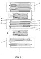
- a multilayer press pack is shown schematically and in sections, wherein it is apparent that composite panel composite components 1 with single-layer assemblies 2 for multilayer printed circuit boards, hereinafter referred to as arrangements 2 alternate.
- the partition plate composite components 1 illustrated with dashed rectangles each have a separating plate 3, also called a pressing plate, separating plate or press plate, on the copper foils 5 provided with a resin layer 4 via non-stick layers 6, here in the form of release films, are attached.
- the entire unit with resin-coated copper foil 5, 4, release film 6, separating plate 3, again release film 6 and coated with synthetic resin 4 copper foil 5, is assembled in advance to the composite component 1, as will be explained below with reference to Figures 2 and 3 in one embodiment becomes.
- the copper foils 4 of the composite components 1 coated with resin 5 become part of the multilayer printed circuit boards, to which further etched inner layers 7 (base materials) and synthetic resin layers (prepreg layers) 8 of the arrangements 2 belong.
- partition plate composite components 1 are provided as units and can be stacked alternately with the multilayer individual layers when producing the printed circuit boards (components), the stacking in the press is substantially simplified, since five components - 4/5, 6, 3 ; 6; 5/4 - can be placed in a single operation at once. This significantly reduces the handling time.
- the etched inner layers 7 realize the desired circuit or conductor structure, and they are glued together with the aid of the prepreg layers 8. This bonding takes place in a press at elevated temperature (for example at 180 ° C) and under pressure or vacuum.
- 20 arrangements 2 can be stacked on top of one another. Between the individual arrangements 2, the separating plate composite components 1 are laid, wherein the separating plates 3 provide a smooth, clean surface of the multilayer printed circuit boards produced.
- the synthetic resin of the prepreg layers 8 begins to flow.
- the resin of the layers 8 is prevented from getting onto the baffles or partition plates 3 in general, and also the resin is prevented from flowing to the edges of the partition plates 3.
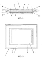
- separate release films are provided as the non-stick layers 6, and these release films 6 are larger than the separation plate 3 and larger than the copper foils 5 with the resin layers 4.
- the copper foils 5 and the partition plate 3 preferably the same size, Even if the copper foils 5 may be slightly smaller than the partition plate 3. Since the release films 6 project on all sides on the partition plate 3, so the liquid resin can be caught. So that the resin can not get between the release sheets 6 to the separation plate 3, the release films 6 are connected together along a glued seam 9 by means of a pressure-sensitive adhesive, an acrylate adhesive or a hot melt adhesive. As a result, the separating plate 3 is enclosed between the sack-like interconnected separating films 6, that is, the separating plate 3 is present in a release film bag, being freely movable in this release film bag.
- the copper foils 5 are also coated with adhesives, e.g. Hot melt adhesives, in particular hot melt adhesives, or acrylate adhesives, glued to the release films 6 in the manner of an adhesive seam 10.
- adhesives e.g. Hot melt adhesives, in particular hot melt adhesives, or acrylate adhesives
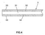
- FIG 4 is now a schematic cross-section of the better representation because of (without hatching) shown by a partition plate 3, which has a special, novel composite structure.
- a middle layer or core layer 3.1 made of a highly thermally conductive metal, such as aluminum or copper, is provided, and this core layer 3.1 is outside on both sides by roll-bonding, generally cold-plating, connected to an outer metal layer 3.2, which consists of a comparison to the core layer 3.1 hard metal is made, such as stainless steel, carbon steel, but also nickel or the like.
- an outer metal layer 3.2 which consists of a comparison to the core layer 3.1 hard metal is made, such as stainless steel, carbon steel, but also nickel or the like.
- Metal When applying these outer hard metal layers 3.2 on the core layer 3.1 by cold plating a fusion of the two metals is brought about, so that there is a solid, surface connection.
- a separator plate 3 was provided with a core layer 3.1 of aluminum having a thickness of about 0.35 mm, which is provided on both sides with an outer metal layer made of stainless steel, with a thickness of approx. 0.075 mm.
- this combined thermal conductivity is quite on the order of that of aluminum, about 170 W / m. K compared to 210 W / m. K.
- the combined thermal expansion of this composite separating plate 3 substantially corresponds to that of steel, in particular stainless steel or carbon steel, ie, for example, it is only 1/25 to 1/50 of the thermal expansion of aluminum alone.
- the composite separating plate 3 can still be provided with outer lubricant coatings 3.3 on both sides or surfaces, wherein these lubricant coatings can be provided in a manner known per se on an olefin basis.
- the present composite partition plate 3 in particular the advantage of combining the actually contradictory effects of high strength and surface hardness on the one hand and good thermal conductivity on the other hand, to ensure a rapid, uniform liquefaction of the epoxy resin during the compression of individual layers for the production of printed circuit board components as well as to prevent any image transfer or damage to the surface and also to ensure reuses of the separating plate 3.
Landscapes
- Engineering & Computer Science (AREA)
- Manufacturing & Machinery (AREA)
- Microelectronics & Electronic Packaging (AREA)
- Laminated Bodies (AREA)
- Control Of Driving Devices And Active Controlling Of Vehicle (AREA)
- Shielding Devices Or Components To Electric Or Magnetic Fields (AREA)
- Window Of Vehicle (AREA)
- Fuel Cell (AREA)
- Cell Separators (AREA)
- Casting Or Compression Moulding Of Plastics Or The Like (AREA)
Description
- Die Erfindung betrifft eine Trennplatte zum Herstellen von Leiterplattenkomponenten unter Verpressen von Einzellagen gemäß dem einleitenden Teil von Anspruch 1. Eine solche Trennplatte ist aus EP 453 629 A bekannt. Im Einzelnen wird dabei eine Metallschicht an einer Seite in einem Plattierband mit einer vergleichsweise härteren Beschichtung versehen.
- Zur Herstellung von aus mehreren Lagen gebildeten Leiterplattenkomponeten, insbesondere von sogenannten Multilayer-Leiterplatten oder kurz Multilayers, ist es bekannt, Einzellagen-Presspakete in entsprechenden Etagen- oder Vakuumpressen bei einer Temperatur von z.B. ca. 180°C miteinander zu verbinden. Die einzelnen Anordnungen bestehen aus Kupferfolien, die zur Herstellung der Leiterbahnen erforderlich sind, sowie aus Kunstharzschichten (Prepreg-Schichten, üblicherweise Epoxidharz-Schichten) bzw. Laminatschichten. Eine der Multilayer-Leiterplatten-Herstellung vergleichbare Herstellung ist bei den sogenannten Basismaterialien für Leiterplatten denkbar, bei denen es sich üblicherweise um eine Kunstharzschicht (Prepreg-Schicht) handelt, die einseitig oder beidseitig mit einer leitenden Schicht (insbesondere einer Kupferfolie) kaschiert ist. Diese Basismaterialien werden auch als sogenannte "Innenlagen" bei der Herstellung von Multilayer-Leiterplatten verwendet und bilden für sich ebenfalls Leiterplattenkomponenten.
- In der Regel werden beim Verpressen wie oben angeführt mehrere Presspakete übereinander in einer Presse angeordnet, und diese Pakete werden durch Trennplatten, auch Pressplatten genannt, voneinander getrennt. Die Trennplatten haben vor allem die Aufgabe, eine einheitliche Druck- und Temperaturverteilung beim Pressen der Einzellagen herbeizuführen, um so qualitativ hochwertige Leiterplattenprodukte zu erzielen. Die Trennplatten bestehen zumeist aus einem Stahlblech oder aber aus Aluminiumblech und werden deshalb auch Trennbleche genannt. Aufgrund der beschriebenen Funktion sollen sie härter sein als die Kupferfolien. Diese Anforderung ist umso bedeutsamer, wenn bedacht wird, dass bei modernen Leiterplatten die Leiterbahnen immer schmäler werden, und auch ihre Abstände immer kleiner werden. Beispielsweise werden bei sog. High Tech-Leiterplatten nach der HDI-Technologie (HDI-High Density Interconnect-Technologie) Kupferfolien mit Dicken von < 12 µm, beispielsweise bloß 5 µm, verwendet. Dabei ist die Gefahr gegeben, dass sich die Leiterbahnen beim Verpressen durch die äußeren Kupferfolien in den Presspaketen durchdrücken können, welcher Effekt als "Imagetransfer" bezeichnet wird. Um diesen Imagetransfer auf kostengünstige Weise zu vermeiden, werden daher in der Multilayer-Technologie zumeist Edelstahlbleche, beispielsweise mit einer Dicke von 1,5 mm oder 1,2 mm, als Trennplatten eingesetzt, da diese Edelstahlbleche eine große Oberflächenhärte aufweisen und überdies, wie dies ebenfalls aus Kostengründen erwünscht ist, wiederholt verwendet werden können.
- Andererseits ist jedoch Edelstahl ein vergleichsweise schlechter Wärmeleiter, wobei gerade bei den vorerwähnten HDI-Leiterplatten mit den immer kleineren Leiterbahn-Breiten und -Abständen eine besonders schnelle und gleichmäßige Wärmeverteilung über die Fläche der einzelnen Lagen wie auch über die gesamte Höhe oder Dicke des zu verpressenden Stapels wichtig ist, um eine entsprechende Qualität zu sichern. Bekannte Trennplatten mit einer besseren Wärmeleitfähigkeit bestehen demgemäß insbesondere aus Aluminium (bzw. einer Aluminium-Legierung; wenn nachstehend Aluminium erwähnt wird, so ist hierunter auch immer eine Aluminium-Legierung zu verstehen), vgl. beispielsweise US 5 153 050 A. Aluminiumbleche als Trennplatten haben jedoch im Vergleich zu Edelstahl-Trennplatten eine wesentlich geringere Oberflächenhärte, und sie weisen z.B. lediglich eine Streckgrenze in der Höhe von ca. 40% der Streckgrenze von Edelstahl auf. Hinzu kommt, dass Aluminium gerade bei der Presstemperatur, bei ca. 180°C bis 200°C, ungefähr 25% seiner Festigkeit (Streckgrenze) verliert und "weichgeglüht" wird. Auch hierdurch kommt es zum vorerwähnten Imagetransfer. Bei der Presstemperatur von 180°C oder 200°C ändert sich bei Edelstahl-Trennplatten hingegen die Festigkeit oder Oberflächenhärte praktisch noch nicht.
- Ein weiterer Nachteil von Aluminium-Trennplatten ist darin zu sehen, dass Aluminium im Vergleich zu den meisten anderen hier in Frage kommenden Metallen einen hohen Wärmeausdehnungskoeffizienten hat. Dadurch ergibt sich beim Pressen wie vorstehend erwähnt, insbesondere nach Verflüssigung des Epoxidharzes, eine Verschiebung der einzelnen zu verpressenden Lagen im Presspaket, wenn sich die Aluminium-Trennplatten ausdehnen, und dies kann insbesondere bei den erwähnten Leiterzugbreiten im Mikrometerbereich, und zwar bereits bei Breiten von z.B. 100 µm und darunter, zu Schäden und somit zum Ausschuss führen.
- Die vorstehend im Zusammenhang mit Aluminium-Trennplatten angeführten Nachteile gelten in vergleichbarer Weise für Trennplatten, die aus Kupfer hergestellt werden. Kupfer wäre ein ausgezeichneter Wärmeleiter und würde so die schnelle und gleichmäßige Wärmeverteilung im Pressstapel sicherstellen, jedoch kann Kupfer bei weitem nicht die Kriterien hinsichtlich Festigkeit bzw. Oberflächenhärte, zur Vermeidung des angeführten Imagetransfers, erfüllen.
- Eine Trennplatte aus Aluminium ist im Übrigen beispielsweise auch aus der US 5 256 474 A bekannt, wobei bei dieser Trennplatte überdies an der Aluminium-Kernschicht eine Antihaftschicht auf beiden Seiten aufgebracht ist, um nach dem Verpressen die Trennplatte leichter von den Kupferlagen der Leiterplatten lösen zu können. Es handelt sich jedoch auch hier um eine Aluminiumblech-Trennplatte mit den vorstehend erwähnten Nachteilen.
- Aus der WO 99/53737 A und der WO 02/058448 A sind andererseits Trennplatten mit einem Substrat aus einer Stahllegierung bekannt, auf dem gemäß WO 99/53737 A weiters zumindest eine Kupferlage aufgebracht ist; diese Kupferlage hat jedoch wie dargelegt eine niedrige Oberflächenhärte, und die Kernschicht, d.h. das Substrat, hat eine niedrige Wärmeleitfähigkeit; dieser Nachteil ist auch bei der Trennplatte gemäß der WO 02/058448 A gegeben, wobei dort metallische Zwischenschichten, insbesondere aus Aluminium, vorgesehen sind, welche äußere Metallschichten, insbesondere aus Kupfer, mit dem Stahl-Substrat verbinden; diese äußeren Metallschichten, insbesondere Kupferschichten, werden in die herzustellenden elektrischen Komponenten eingebaut, sind also überdies genau genommen nicht Teil der eigentlichen Trennplatte.
- Es ist nun Aufgabe der Erfindung, eine Trennplatte wie eingangs angeführt vorzusehen, mit der den erwähnten, aufgrund der zusammenhängenden Materialeigenschaften einander widersprechenden Anforderungen betreffend gleichmäßige Wärmeverteilung einerseits und hohe Festigkeit bzw. Oberflächenhärte andererseits in zufriedenstellender Weise entsprochen werden kann. Die Erfindung basiert dabei auf der Überlegung, die Trennplatten als Verbundwerkstoff-Trennplatten auszuführen und so die Eigenschaften verschiedener Metalle in Kombination vorzusehen und zu nutzen.
- Zur Lösung dieser Aufgabe sieht die Erfindung eine Trennplatte mit den Merkmalen des unabhängigen Anspruches vor. Vorteilhafte Ausführungsformen und Weiterbildungen sind in den Unteransprüchen definiert.
- Bei der erfindungsgemäßen Trennplatte liegt somit eine Kernschicht oder Mittelschicht aus einem hoch wärmeleitfähigen Metall wie Aluminium oder Kupfer vor, und diese Kernschicht wird beidseitig durch Kaltplattieren bzw. Walzplattieren mit einem harten Metall, wie z.B. Edelstahl, Kohlenstoffstahl, aber auch Nickel oder dergl., verbunden. Diese Hartmetallplattierung kann dabei vergleichsweise dünn sein, beispielsweise in der Größenordnung von ca. 0,075 mm dick sein, wogegen der Kern, z.B. aus Aluminium oder Kupfer, beispielsweise eine Dicke von 0,35 mm aufweist. Beim Walzplattieren bzw. Kaltplattieren erfolgt eine flächige Verbindung der Metalle in der Art einer Verschmelzung, wobei sich auch als vorteilhafter Effekt ergibt, dass bei einer Erwärmung die Wärmeausdehnung nur entsprechend jener der Hartmetallplattierung erfolgen kann, d.h. es kommt nicht mehr zu den verhältnismäßig starken-Wärmeausdehnungen der wärmeleitfähigen Metalle wie Aluminium oder Kupfer, wenn diese Metalle allein für die Trennplatte verwendet werden. Hinzu kommt, dass die Wärmedehnung, beispielsweise von Stahl, die von Haus aus wesentlich geringer ist als jene von Aluminium, erst bei einer vergleichsweise hohen Temperatur zum Tragen kommt, diese hohe Temperatur aber beim gegenständlichen Verpressen von Einzellagen zur Herstellung von Leiterplattenkomponenten nicht auftritt. Beispielsweise würden Aluminium-Trennplatten in einer Größe von 600x450 mm eine Dehnung um ca. 5 mm in jeder Richtung erfahren, eine Trennplatte aus Stahl mit diesen Abmessungen an sich - jedoch erst bei hohen Temperaturen - nur eine Dehnung um ca. 2 mm, jedoch erst bei höheren Temperaturen, bei den fraglichen Temperaturen von 180°C oder 200°C beim Verpressen hingegen nur im Ausmaß von 0,1 mm - 0,2 mm. An diese geringe Dehnung muss sich zwangsläufig aufgrund der Verschmelzung mit dem harten Plattierungsmaterial auch die Kernschicht aus wärmeleitfähigem Metall angleichen.
- Ein weiterer Vorteil der erfindungsgemäßen Trennplatte liegt darin, dass trotz der Herstellung als Verbundplatte niedrige Kosten auch deshalb erzielt werden können, da Aluminium ein relativ niedriges spezifisches Gewicht hat, so dass sich der pro Kilogramm zu berechnende Einkaufspreis für Aluminium relativ gering im Verkaufspreis für die Trennplatten niederschlägt, der nach der Fläche der Trennplatten berechnet wird.
- Insgesamt wird durch die Erfindung somit eine Trennplatte erhalten, die einerseits aufgrund der guten Wärmeleitfähigkeit des hiefür maßgeblichen Kerns (bezogen auf die Gesamtmasse der Trennplatte liegen ca. 75% wärmeleitfähiges Material, z.B. Aluminium, und nur 25% Hartmetall, z.B. Stahl, vor) eine gleichmäßige Wärmeverteilung über die Fläche und die Stapelhöhe beim Verpressen sicherstellt, d.h. das Epoxidharz wird bei Verwendung der erfindungsgemäßen Trennplatten praktisch überall auf einmal flüssig, und die andererseits durch das aufplattierte Hartmetall die erforderliche Oberflächenhärte besitzt, um den unerwünschten Imagetransfer zu vermeiden, und um auch eine oftmalige Verwendung der Trennplatte in Verpressvorgängen zu ermöglichen. Zum Verpressen ist es dabei auch mit Vorteil möglich, auf der äußeren, harten Metallschicht ein Gleitmittel, wie z.B. ein Gleitmittel auf Olefinbasis, aufzubringen.
- Die Erfindung wird nachstehend anhand eines in der Zeichnung dargestellten, besonders vorteilhaften Ausführungsbeispiels, auf das sie jedoch nicht beschränkt sein soll, noch weiter erläutert. Es zeigen im Einzelnen:
- Fig. 1 in einer schematischen Ansicht einen Aufbau eines Multilayer-Presspakets mit mehreren Einzellagen und Trennplatten-Verbundkomponenten;
- Fig. 2 schematisch in einer Ansicht eine Trennplatten-Verbundkomponente mit einem Trennfoliensack;
- Fig. 3 eine schematische Draufsicht auf eine derartige Trennplatten-Verbundkomponente gemäß Fig. 2; und
- Fig. 4 einen schematischen Schnitt durch eine Trennplatte, wie sie in den Anordnungen von Fig. 1 bis 3 verwendet werden kann, und wie sie Gegenstand der vorliegenden Erfindung ist.
- In Fig. 1 ist ein Multilayer-Presspaket schematisch und ausschnittsweise gezeigt, wobei ersichtlich ist, dass Trennplatten-Verbundkomponenten 1 mit Einzellagen-Anordnungen 2 für Multilayer-Leiterplatten, nachstehend kurz Anordnungen 2 genannt, abwechseln. Die mit strichlierten Rechtecken veranschaulichten Trennplatten-Verbundkomponenten 1 weisen je eine Trennplatte 3, auch Pressplatte, Trennblech oder Pressblech genannt, auf, an der mit einer Harzschicht 4 versehene Kupferfolien 5 über Antihaftlagen 6, hier in Form von Trennfolien, angebracht werden. Die gesamte Einheit mit harzbeschichteter Kupferfolie 5, 4, Trennfolie 6, Trennblech 3, neuerlich Trennfolie 6 und mit Kunstharz 4 beschichtete Kupferfolie 5, wird im Vorhinein zur Verbundkomponente 1 zusammengefügt, wie dies nachstehend anhand der Figuren 2 und 3 in einem Ausführungsbeispiel näher erläutert werden wird.
- Die mit Harz 5 beschichteten Kupferfolien 4 der Verbundkomponenten 1 werden Bestandteil der Multilayer-Leiterplatten, zu denen weiters geätzte Innenlagen 7 (Basismaterialien) und Kunstharzschichten (Prepreg-Schichten) 8 der Anordnungen 2 gehören.
- Dadurch, dass derartige Trennplatten-Verbundkomponenten 1 als Einheiten vorgesehen und beim Herstellen der Leiterplatten(komponenten) abwechselnd mit den Multilayer-Einzellagen übereinander gestapelt werden können, wird das Stapeln in der Presse wesentlich vereinfacht, da fünf Komponenten - 4/5;6;3;6;5/4 - in einem einzigen Vorgang auf einmal gelegt werden können. Dies reduziert die Handlingzeit wesentlich. Die geätzten Innenlagen 7 realisieren die gewünschte Schaltung bzw. Leiterstruktur, und sie werden mit Hilfe der Prepreg-Schichten 8 miteinander verklebt. Dieses Verbinden erfolgt in einer Presse bei erhöhter Temperatur (z.B. bei 180°C) sowie bei Druck oder aber Vakuum. In einem solchen Presspaket, wie es schematisch zum Teil in Fig. 1 veranschaulicht ist, können durchaus 20 Anordnungen 2 übereinander geschichtet sein. Zwischen den einzelnen Anordnungen 2 werden die Trennblech-Verbundkomponenten 1 gelegt, wobei die Trennbleche 3 für eine glatte, saubere Oberfläche der hergestellten Multilayer-Leiterplatten sorgen.
- Während des definierten Presszyklus beginnt das Kunstharz der Prepreg-Schichten 8 zu fließen. Dadurch, dass die Antihaftlagen oder Trennlagen 6 vorgesehen sind, wird verhindert, dass das Harz der Schichten 8 auf die Trennbleche oder allgemein Trennplatten 3 gelangt, und es wird auch verhindert, dass das Harz zu den Kanten der Trennplatten 3 fließt.
- Gemäß Fig. 2 und 3 sind gesonderte Trennfolien als Antihaftlagen 6 vorgesehen, und diese Trennfolien 6 sind größer als die Trennplatte 3 und auch größer als die Kupferfolien 5 mit den Harzschichten 4. Wie aus Fig. 2 ersichtlich, sind in diesem Fall die Kupferfolien 5 und die Trennplatte 3 bevorzugt gleich groß, auch wenn die Kupferfolien 5 geringfügig kleiner sein können als die Trennplatte 3. Da die Trennfolien 6 allseitig über die Trennplatte 3 vorstehen, kann so das flüssige Harz gefangen werden. Damit das Harz auch nicht zwischen den Trennfolien 6 zur Trennplatte 3 gelangen kann, sind die Trennfolien 6 miteinander längs einer Klebenaht 9 mit Hilfe eines druckempfindlichen Klebers, eines Acrylatklebers bzw. eines Schmelzklebers verbunden. Dadurch ist die Trennplatte 3 zwischen den sackartig miteinander verbundenen Trennfolien 6 eingeschlossen, das heißt die Trennplatte 3 liegt in einem Trennfoliensack vor, wobei sie in diesem Trennfoliensack frei beweglich angeordnet ist.
- Die Kupferfolien 5 sind andererseits ebenfalls mit Hilfe von Klebern, z.B. Schmelzklebern, insbesondere Heißschmelzklebern, oder Acrylatklebern, in der Art einer Klebenaht 10 an den Trennfolien 6 angeklebt.
- In Fig.4 ist nun ein schematischer Querschnitt der besseren Darstellung wegen (ohne Schraffuren) durch eine Trennplatte 3 gezeigt, die einen speziellen, neuartigen Verbund-Aufbau aufweist. Im Einzelnen ist eine Mittelschicht oder Kernschicht 3.1 aus einem hoch-wärmeleitfähigen Metall, wie beispielsweise Aluminium oder aber auch Kupfer, vorgesehen, und diese Kernschicht 3.1 ist beidseitig außen durch Walzplattieren, allgemein Kaltplattieren, mit einer äußeren Metallschicht 3.2 verbunden, die aus einem im Vergleich zur Kernschicht 3.1 harten Metall besteht, wie beispielsweise aus Edelstahl, Kohlenstoffstahl, aber auch Nickel oder dergl. Metall. Beim Aufbringen dieser äußeren, harten Metallschichten 3.2 auf der Kernschicht 3.1 durch Kaltplattieren wird eine Verschmelzung der beiden Metalle herbeigeführt, so dass sich eine feste, flächige Verbindung ergibt. Diese feste, flächige Verbindung führt bei der fertigen Trennplatte 3 dazu, dass sich die Kernschicht 3.1 aus dem vergleichsweise (also relativ zu den äußeren Metallschichten 3.2) gut wärmeleitenden Metall nicht mehr in einem derartigen Ausmaß dehnen kann, wenn sie erwärmt wird, wie in dem Fall, wenn sie frei vorliegt, d.h. es ergibt sich insgesamt eine Wärmedehnung entsprechend jener der äußeren Metallschichten 3.2 aus hartem Metall.
- In einem Beispiel wurde eine Trennplatte 3 mit einer Kernschicht 3.1 aus Aluminium mit einer Dicke von ungefähr 0,35 mm vorgesehen, welche beidseitig mit einer äußeren Metallschicht aus Edelstahl, mit einer Dicke von ca. 0,075 mm, versehen wurde. Es ergibt sich dabei zwar eine kombinierte Wärmeleitfähigkeit, die etwas geringer ist als jene von Aluminium (bzw. der Aluminiumlegierung) allein, jedoch liegt diese kombinierte Wärmeleitfähigkeit durchaus in der Größenordnung von jener von Aluminium, etwa bei 170 W/m . K im Vergleich zu 210 W/m . K. Die kombinierte Wärmedehnung dieser Verbund-Trennplatte 3 entspricht andererseits im Wesentlichen jener von Stahl, insbesondere Edelstahl oder aber Kohlenstoffstahl, d.h. sie beträgt beispielsweise nur 1/25 bis 1/50 der Wärmedehnung von Aluminium allein.
- Ein anderes konkretes Beispiel, dass sich bei praktischen Tests besonders bewährt hat, hat bei einer Trennplatten-Gesamtdicke von 0,5 mm beispielsweise folgenden Aufbau:
- 0,05 mm Edelstahl (oder Stahl)
- 0,40 mm Aluminium
- 0,05 mm Edelstahl (oder Stahl)
- Es ergeben sich daher folgende physikalische Werte, anhand derer die Bedeutung der vorliegenden Verbund-Trennplatte deutlich wird:
Aluminium Edelstahl Verbundwerkstoff (Trennplatte) Festigkeit/Oberflächen-härte in Mpa ca. 240 ca. 800 ca. 800 Wärmeleitfähigkeit in W / m.K 210 25 170 Wärmeausdehnung in 10-6.K-1 23,5 10,5 10,5 - Aus Fig.4 ist noch ersichtlich, dass die Verbund-Trennplatte 3 noch mit äußeren Gleitmittel-Beschichtungen 3.3 auf beiden Seiten oder Oberflächen versehen sein kann, wobei diese Gleitmittel-Beschichtungen in an sich bekannter Weise auf einer Olefinbasis vorgesehen sein können.
- Eine derartige Verbund-Trennplatte 3 mit den unterschiedlichen Metallen kann in einer Trennplatten-Verbundkomponente wie vorstehend anhand der Fig.1 bis 3 beschrieben verwendet werden, sie kann jedoch selbstverständlich auch in Presspaketen in einer Einzelanordnung, wie dies aus dem Stand der Technik, etwa gemäß US 5 356 474 A, an sich bekannt ist, in gleicher Weise eingesetzt werden. Da wie dort erbringt die vorliegende Verbund-Trennplatte 3 im Besonderen den Vorteil der Kombination der einander eigentlich widersprechenden Effekte der hohen Festigkeit und Oberflächenhärte einerseits sowie der guten Wärmeleitfähigkeit andererseits, um beim Verpressen von Einzellagen zur Herstellung von Leiterplattenkomponenten ein rasches, gleichmäßiges Verflüssigen des Epoxidharzes sicherzustellen sowie einen Imagetransfer bzw. Beschädigungen der Oberfläche hintanzuhalten und auch Wiederverwendungen der Trennplatte 3 sicherzustellen.
Claims (9)
- Trennplatte (3) zum Herstellen von Leiterplattenkomponenten unter Verpressen von Einzellagen, welche Trennplatte (3) eine metallische Kernschicht (3.1) und eine Beschichtung aus einem Metall aufweist, das im Vergleich zur metallischen Kernschicht (3.1) eine große Oberflächenhärte aufweist, dadurch gekennzeichnet, dass die Beschichtung an beiden Seiten der Kernschicht (3.1) aus durch Kaltplattieren auf die Kernschicht aufgebrachten äußeren Metallschichten (3.2) besteht, wobei die metallische Kernschicht (3.1) aus einem im Vergleich zu den beiden äußeren Metallschichten (3.2) gut wärmeleitenden Metall besteht.
- Trennplatte nach Anspruch 1, dadurch gekennzeichnet, dass die äußeren Metallschichten (3.2) durch Walzplattieren aufgebracht ist.
- Trennplatte nach Anspruch 1 oder 2, dadurch gekennzeichnet, dass die äußeren Metallschichten (3.2) aus Stahl, wie z.B. Edelstahl oder Kohlenstoffstahl, besteht.
- Trennplatte nach Anspruch 1 oder 2, dadurch gekennzeichnet, dass die äußeren Metallschichten (3.2) aus Nickel bestehen.
- Trennplatte nach einem der Ansprüche 1 bis 4, dadurch gekennzeichnet, dass die Kernschicht (3.1) aus Aluminium besteht.
- Trennplatte nach einem der Ansprüche 1 bis 4, dadurch gekennzeichnet, dass die Kernschicht (3.1) aus Kupfer besteht.
- Trennplatte nach einem der Ansprüche 1 bis 6, dadurch gekennzeichnet, dass die Kernschicht (3.1) eine Dicke von ca. 0,35 mm aufweist.
- Trennplatte nach einem der Ansprüche 1 bis 7, dadurch gekennzeichnet, dass die äußeren Metallschichten (3.2) eine Dicke von ca. 0,075 mm aufweist.
- Trennplatte nach einem der Ansprüche 1 bis 8, dadurch gekennzeichnet, dass auf den äußeren Metallschichten (3.2) ein Gleitmittel (3.3), z.B. auf Olefinbasis, aufgebracht ist.
Priority Applications (1)
| Application Number | Priority Date | Filing Date | Title |
|---|---|---|---|
| AT03779556T ATE332626T1 (de) | 2002-12-27 | 2003-12-29 | Trennplatte zum herstellen von leiterplattenkomponenten |
Applications Claiming Priority (3)
| Application Number | Priority Date | Filing Date | Title |
|---|---|---|---|
| AT0193702A AT411893B (de) | 2002-12-27 | 2002-12-27 | Trennplatte zum herstellen von leiterplattenkomponenten |
| AT19372002 | 2002-12-27 | ||
| PCT/AT2003/000389 WO2004060036A1 (de) | 2002-12-27 | 2003-12-29 | Trennplatte zum herstellen von leiterplattenkomponenten |
Publications (2)
| Publication Number | Publication Date |
|---|---|
| EP1576864A1 EP1576864A1 (de) | 2005-09-21 |
| EP1576864B1 true EP1576864B1 (de) | 2006-07-05 |
Family
ID=29588469
Family Applications (1)
| Application Number | Title | Priority Date | Filing Date |
|---|---|---|---|
| EP03779556A Expired - Lifetime EP1576864B1 (de) | 2002-12-27 | 2003-12-29 | Trennplatte zum herstellen von leiterplattenkomponenten |
Country Status (9)
| Country | Link |
|---|---|
| US (1) | US7097915B2 (de) |
| EP (1) | EP1576864B1 (de) |
| KR (1) | KR101118696B1 (de) |
| CN (1) | CN100471366C (de) |
| AT (2) | AT411893B (de) |
| AU (1) | AU2003287760A1 (de) |
| DE (1) | DE50304175D1 (de) |
| TW (1) | TW200418353A (de) |
| WO (1) | WO2004060036A1 (de) |
Families Citing this family (8)
| Publication number | Priority date | Publication date | Assignee | Title |
|---|---|---|---|---|
| DE102005034499B4 (de) * | 2005-07-20 | 2011-03-31 | Wickeder Westfalenstahl Gmbh | Presspaketaufbau zum Verpressen von Multilayern bzw. Presse zur Verpressung bzw. Herstellung von Multilayern |
| CN100477889C (zh) * | 2005-09-19 | 2009-04-08 | 金像电子股份有限公司 | 软硬复合板的制造方法 |
| DE102007054171A1 (de) * | 2007-02-28 | 2008-09-04 | Backhaus, Monika | Press- und Heizsystem zum Verpressen eines Multilayerpresspaketes |
| KR101017934B1 (ko) * | 2009-05-18 | 2011-03-04 | (주)티에이치엔 | 정션박스용 버스 플레이트 및 그 제조 방법 |
| CN104955279B (zh) * | 2015-05-22 | 2017-12-29 | 苏州市嘉明机械制造有限公司 | 一种高强度防凹陷镜板的生产工艺 |
| CN105568203A (zh) * | 2015-12-10 | 2016-05-11 | 苏州市嘉明机械制造有限公司 | 一种基于等离子喷涂的抗刮绝缘镜板的制造方法 |
| CN105420660A (zh) * | 2015-12-10 | 2016-03-23 | 苏州市嘉明机械制造有限公司 | 一种基于等离子喷涂的耐磨绝缘镜板的制造方法 |
| CN112499255A (zh) * | 2020-11-13 | 2021-03-16 | 枣庄睿诺电子科技有限公司 | 一种冷却接驳设备 |
Family Cites Families (22)
| Publication number | Priority date | Publication date | Assignee | Title |
|---|---|---|---|---|
| US3462827A (en) * | 1965-10-01 | 1969-08-26 | Olin Mathieson | Process for obtaining a composite article |
| US3778238A (en) * | 1972-04-14 | 1973-12-11 | D Tyler | Composite metal article |
| US3952938A (en) * | 1973-12-10 | 1976-04-27 | Clad Metals, Inc. | Method of making multiple member composite metal products |
| US4103076A (en) * | 1973-12-10 | 1978-07-25 | Clad Metals, Inc. | Clad metal product of Cu, Al and stainless steel |
| US4167606A (en) * | 1976-11-22 | 1979-09-11 | Clad Metals, Inc. | Multiple member clad metal products |
| US3861884A (en) * | 1973-12-13 | 1975-01-21 | Olin Corp | Composite metal article |
| US4264030A (en) * | 1979-09-06 | 1981-04-28 | Dimark, Inc. | Process for rolling edge of stainless steel clad aluminum cooking vessels |
| US4759486A (en) * | 1984-03-01 | 1988-07-26 | Copperweld Corporation | Controlled environment chamber for use in cladding a nonaluminum core with aluminum |
| US5256474A (en) | 1986-11-13 | 1993-10-26 | Johnston James A | Method of and apparatus for manufacturing printed circuit boards |
| JPS63172639A (ja) * | 1987-01-12 | 1988-07-16 | 住友金属工業株式会社 | 熱伝導の優れた両面クラツド鋼帯 |
| US5215951A (en) * | 1987-10-29 | 1993-06-01 | Sumitomo Chemical Company, Limited | Process for producing α-olefin polymer |
| JPH049498A (ja) * | 1990-04-26 | 1992-01-14 | Nkk Corp | 優れた剥離性および高い硬度を有するニツケル‐燐合金めつき金属板およびその製造方法 |
| JPH04319431A (ja) * | 1991-04-19 | 1992-11-10 | Nippon Steel Corp | 軽量で加工性の優れた自動車用薄鋼板クラッドアルミニウム薄板およびその製造方法 |
| US5153050A (en) | 1991-08-27 | 1992-10-06 | Johnston James A | Component of printed circuit boards |
| JPH11170382A (ja) * | 1997-12-08 | 1999-06-29 | Shin Kobe Electric Mach Co Ltd | 積層板の製造法および積層板の成形用プレート |
| WO1999053737A1 (en) * | 1998-04-10 | 1999-10-21 | R.E. Service Company, Inc. | Steel alloy separator sheets and copper/steel laminated sheets for use in manufacturing printed circuit boards |
| US6129990A (en) * | 1998-04-10 | 2000-10-10 | R. E. Service Company, Inc. | Copper/steel laminated sheet for use in manufacturing printed circuit boards |
| CN2340146Y (zh) * | 1998-04-16 | 1999-09-22 | 朱科 | 双面金属薄膜 |
| US6060438A (en) * | 1998-10-27 | 2000-05-09 | D. A. Stuart | Emulsion for the hot rolling of non-ferrous metals |
| AT409612B (de) * | 1999-01-21 | 2002-09-25 | Boehler Bleche Gmbh | Plattenförmiges presswerkzeug und verfahren zu dessen herstellung |
| US6329075B1 (en) * | 2000-02-03 | 2001-12-11 | Reycan, L.P. | Electrical conductivity and high strength aluminum alloy composite material and methods of manufacturing and use |
| US20020124938A1 (en) * | 2000-12-28 | 2002-09-12 | Henrich Peter J. | Apparatus and method for producing non- or lightly-embossed panels |
-
2002
- 2002-12-27 AT AT0193702A patent/AT411893B/de not_active IP Right Cessation
-
2003
- 2003-07-25 US US10/627,042 patent/US7097915B2/en not_active Expired - Fee Related
- 2003-12-18 TW TW092136038A patent/TW200418353A/zh unknown
- 2003-12-29 WO PCT/AT2003/000389 patent/WO2004060036A1/de not_active Ceased
- 2003-12-29 CN CNB2003801073419A patent/CN100471366C/zh not_active Expired - Fee Related
- 2003-12-29 EP EP03779556A patent/EP1576864B1/de not_active Expired - Lifetime
- 2003-12-29 AU AU2003287760A patent/AU2003287760A1/en not_active Abandoned
- 2003-12-29 KR KR1020057012178A patent/KR101118696B1/ko not_active Expired - Fee Related
- 2003-12-29 DE DE50304175T patent/DE50304175D1/de not_active Expired - Lifetime
- 2003-12-29 AT AT03779556T patent/ATE332626T1/de active
Also Published As
| Publication number | Publication date |
|---|---|
| EP1576864A1 (de) | 2005-09-21 |
| DE50304175D1 (de) | 2006-08-17 |
| US7097915B2 (en) | 2006-08-29 |
| ATE332626T1 (de) | 2006-07-15 |
| CN1732725A (zh) | 2006-02-08 |
| CN100471366C (zh) | 2009-03-18 |
| AT411893B (de) | 2004-07-26 |
| KR20050089990A (ko) | 2005-09-09 |
| TW200418353A (en) | 2004-09-16 |
| ATA19372002A (de) | 2003-12-15 |
| WO2004060036A1 (de) | 2004-07-15 |
| AU2003287760A1 (en) | 2004-07-22 |
| US20040151941A1 (en) | 2004-08-05 |
| KR101118696B1 (ko) | 2012-05-30 |
Similar Documents
| Publication | Publication Date | Title |
|---|---|---|
| DE69505553T2 (de) | MONOLITHISCHE MIKROELEKTRONISCHE SCHALTUNGSMODULE AUS FLüSSIGKRISTALLPOLYMER | |
| DE112006002571B4 (de) | Kupferplattierter Schichtstoff, gedruckte Leiterplatten, mehrschichtige gedruckte Leiterplatte und Verfahren zum Herstellen derselben | |
| DE68925688T2 (de) | Trennfolie aus einem Laminat | |
| DE102004016744B4 (de) | Mehrschichtige gedruckte Schaltungskarte und Verfahren zur Herstellung derselben | |
| DE10309188B4 (de) | Steif-flexible Leiterplatte und Verfahren zu deren Herstellung | |
| DE69012019T2 (de) | Aussenschichtmaterial von einer gedruckten mehrschichtleiterplatte und verfahren zu deren herstellung. | |
| DE2823669B2 (de) | Heißverformbare Kunstharz-Schichtpreßstoffplatte, sowie Verfahren zum Verformen dieser Platten | |
| EP1576864B1 (de) | Trennplatte zum herstellen von leiterplattenkomponenten | |
| DE19522338B4 (de) | Chipträgeranordnung mit einer Durchkontaktierung | |
| EP1910068B1 (de) | Presspaketaufbau zum verpressen von multilayern bzw. presse zur verpressung bzw. herstellung von multilayern | |
| DE2735261A1 (de) | Verfahren zum herstellen einer verbundplatte | |
| EP1401636B1 (de) | Trennblech bzw. verfahren zur herstellung eines trennbleches für ein multilayerpresspaket | |
| DE4118814A1 (de) | Verfahren und vorrichtung zum verkleben von mehrlagenplatten | |
| EP1097615B1 (de) | Verfahren zur verbindung von kupferfolien und trennblechen | |
| EP1448378B1 (de) | Trennplatten-verbundkomponente zur herstellung von leiterplattenkomponenten und verfahren zur herstellung einer solchen verbundkomponente | |
| DE102004041309A1 (de) | Verfahren zum Löten von mikrostrukturierten, metallischen Schichtblechen und Schichtblock eines Mikrowärmeübertragers oder -reaktors, insbesondere hergestellt nach dem Verfahren | |
| DE3302857A1 (de) | Verfahren zum herstellen von vorlaminaten fuer starrflexible leiterplatten | |
| DE10038429C2 (de) | Verbundlaminat und Verfahren zur Herstellung desselben | |
| DE19859613C2 (de) | Presspaketaufbau und Verfahren zu dessen Herstellung | |
| DE2444698A1 (de) | Einrichtung zum verpressen grossflaechiger mehrlagiger leiterplatten | |
| AT516609B1 (de) | Elektrisch leitende Bauteile mit verbesserter Haftung und Verfahren zu deren Herstellung | |
| DE3541977A1 (de) | Mehrschicht-laminat zum verpressen von gedruckten schaltungsteilen untereinander oder mit folien | |
| EP1457616A1 (de) | Verbundplatte aus Leichtmetall | |
| DE3220272C2 (de) | Verfahren zum Ausbilden einer mehrschichtigen gedruckten Platte | |
| DE3609239C2 (de) |
Legal Events
| Date | Code | Title | Description |
|---|---|---|---|
| PUAI | Public reference made under article 153(3) epc to a published international application that has entered the european phase |
Free format text: ORIGINAL CODE: 0009012 |
|
| 17P | Request for examination filed |
Effective date: 20050616 |
|
| AK | Designated contracting states |
Kind code of ref document: A1 Designated state(s): AT BE BG CH CY CZ DE DK EE ES FI FR GB GR HU IE IT LI LU MC NL PT RO SE SI SK |
|
| AX | Request for extension of the european patent |
Extension state: AL LT LV MK |
|
| GRAP | Despatch of communication of intention to grant a patent |
Free format text: ORIGINAL CODE: EPIDOSNIGR1 |
|
| DAX | Request for extension of the european patent (deleted) | ||
| RBV | Designated contracting states (corrected) |
Designated state(s): AT BE BG CH CY CZ DE DK EE ES FI FR GB GR HU IE IT LI LU MC NL PT RO SE SI SK TR |
|
| RIC1 | Information provided on ipc code assigned before grant |
Ipc: B32B 37/00 20060101ALI20060124BHEP Ipc: H05K 3/46 20060101AFI20060124BHEP |
|
| GRAS | Grant fee paid |
Free format text: ORIGINAL CODE: EPIDOSNIGR3 |
|
| GRAA | (expected) grant |
Free format text: ORIGINAL CODE: 0009210 |
|
| AK | Designated contracting states |
Kind code of ref document: B1 Designated state(s): AT BE BG CH CY CZ DE DK EE ES FI FR GB GR HU IE IT LI LU MC NL PT RO SE SI SK TR |
|
| PG25 | Lapsed in a contracting state [announced via postgrant information from national office to epo] |
Ref country code: IT Free format text: LAPSE BECAUSE OF FAILURE TO SUBMIT A TRANSLATION OF THE DESCRIPTION OR TO PAY THE FEE WITHIN THE PRESCRIBED TIME-LIMIT;WARNING: LAPSES OF ITALIAN PATENTS WITH EFFECTIVE DATE BEFORE 2007 MAY HAVE OCCURRED AT ANY TIME BEFORE 2007. THE CORRECT EFFECTIVE DATE MAY BE DIFFERENT FROM THE ONE RECORDED. Effective date: 20060705 Ref country code: RO Free format text: LAPSE BECAUSE OF FAILURE TO SUBMIT A TRANSLATION OF THE DESCRIPTION OR TO PAY THE FEE WITHIN THE PRESCRIBED TIME-LIMIT Effective date: 20060705 Ref country code: GB Free format text: LAPSE BECAUSE OF FAILURE TO SUBMIT A TRANSLATION OF THE DESCRIPTION OR TO PAY THE FEE WITHIN THE PRESCRIBED TIME-LIMIT Effective date: 20060705 Ref country code: IE Free format text: LAPSE BECAUSE OF FAILURE TO SUBMIT A TRANSLATION OF THE DESCRIPTION OR TO PAY THE FEE WITHIN THE PRESCRIBED TIME-LIMIT Effective date: 20060705 Ref country code: CZ Free format text: LAPSE BECAUSE OF FAILURE TO SUBMIT A TRANSLATION OF THE DESCRIPTION OR TO PAY THE FEE WITHIN THE PRESCRIBED TIME-LIMIT Effective date: 20060705 Ref country code: SI Free format text: LAPSE BECAUSE OF FAILURE TO SUBMIT A TRANSLATION OF THE DESCRIPTION OR TO PAY THE FEE WITHIN THE PRESCRIBED TIME-LIMIT Effective date: 20060705 Ref country code: FI Free format text: LAPSE BECAUSE OF FAILURE TO SUBMIT A TRANSLATION OF THE DESCRIPTION OR TO PAY THE FEE WITHIN THE PRESCRIBED TIME-LIMIT Effective date: 20060705 Ref country code: SK Free format text: LAPSE BECAUSE OF FAILURE TO SUBMIT A TRANSLATION OF THE DESCRIPTION OR TO PAY THE FEE WITHIN THE PRESCRIBED TIME-LIMIT Effective date: 20060705 Ref country code: NL Free format text: LAPSE BECAUSE OF FAILURE TO SUBMIT A TRANSLATION OF THE DESCRIPTION OR TO PAY THE FEE WITHIN THE PRESCRIBED TIME-LIMIT Effective date: 20060705 |
|
| REG | Reference to a national code |
Ref country code: GB Ref legal event code: FG4D Free format text: NOT ENGLISH |
|
| REG | Reference to a national code |
Ref country code: CH Ref legal event code: EP |
|
| REG | Reference to a national code |
Ref country code: IE Ref legal event code: FG4D Free format text: LANGUAGE OF EP DOCUMENT: GERMAN |
|
| REF | Corresponds to: |
Ref document number: 50304175 Country of ref document: DE Date of ref document: 20060817 Kind code of ref document: P |
|
| PG25 | Lapsed in a contracting state [announced via postgrant information from national office to epo] |
Ref country code: DK Free format text: LAPSE BECAUSE OF FAILURE TO SUBMIT A TRANSLATION OF THE DESCRIPTION OR TO PAY THE FEE WITHIN THE PRESCRIBED TIME-LIMIT Effective date: 20061005 Ref country code: SE Free format text: LAPSE BECAUSE OF FAILURE TO SUBMIT A TRANSLATION OF THE DESCRIPTION OR TO PAY THE FEE WITHIN THE PRESCRIBED TIME-LIMIT Effective date: 20061005 Ref country code: BG Free format text: LAPSE BECAUSE OF FAILURE TO SUBMIT A TRANSLATION OF THE DESCRIPTION OR TO PAY THE FEE WITHIN THE PRESCRIBED TIME-LIMIT Effective date: 20061005 |
|
| PG25 | Lapsed in a contracting state [announced via postgrant information from national office to epo] |
Ref country code: ES Free format text: LAPSE BECAUSE OF FAILURE TO SUBMIT A TRANSLATION OF THE DESCRIPTION OR TO PAY THE FEE WITHIN THE PRESCRIBED TIME-LIMIT Effective date: 20061016 |
|
| NLV1 | Nl: lapsed or annulled due to failure to fulfill the requirements of art. 29p and 29m of the patents act | ||
| PG25 | Lapsed in a contracting state [announced via postgrant information from national office to epo] |
Ref country code: PT Free format text: LAPSE BECAUSE OF FAILURE TO SUBMIT A TRANSLATION OF THE DESCRIPTION OR TO PAY THE FEE WITHIN THE PRESCRIBED TIME-LIMIT Effective date: 20061205 |
|
| PG25 | Lapsed in a contracting state [announced via postgrant information from national office to epo] |
Ref country code: MC Free format text: LAPSE BECAUSE OF NON-PAYMENT OF DUE FEES Effective date: 20061231 Ref country code: BE Free format text: LAPSE BECAUSE OF NON-PAYMENT OF DUE FEES Effective date: 20061231 |
|
| GBV | Gb: ep patent (uk) treated as always having been void in accordance with gb section 77(7)/1977 [no translation filed] |
Effective date: 20060705 |
|
| REG | Reference to a national code |
Ref country code: IE Ref legal event code: FD4D |
|
| EN | Fr: translation not filed | ||
| PLBE | No opposition filed within time limit |
Free format text: ORIGINAL CODE: 0009261 |
|
| STAA | Information on the status of an ep patent application or granted ep patent |
Free format text: STATUS: NO OPPOSITION FILED WITHIN TIME LIMIT |
|
| 26N | No opposition filed |
Effective date: 20070410 |
|
| BERE | Be: lapsed |
Owner name: C2C TECHNOLOGIE FUR LEITERPLATTEN GMBH Effective date: 20061231 |
|
| PG25 | Lapsed in a contracting state [announced via postgrant information from national office to epo] |
Ref country code: GR Free format text: LAPSE BECAUSE OF FAILURE TO SUBMIT A TRANSLATION OF THE DESCRIPTION OR TO PAY THE FEE WITHIN THE PRESCRIBED TIME-LIMIT Effective date: 20061006 Ref country code: FR Free format text: LAPSE BECAUSE OF FAILURE TO SUBMIT A TRANSLATION OF THE DESCRIPTION OR TO PAY THE FEE WITHIN THE PRESCRIBED TIME-LIMIT Effective date: 20070511 |
|
| PG25 | Lapsed in a contracting state [announced via postgrant information from national office to epo] |
Ref country code: EE Free format text: LAPSE BECAUSE OF FAILURE TO SUBMIT A TRANSLATION OF THE DESCRIPTION OR TO PAY THE FEE WITHIN THE PRESCRIBED TIME-LIMIT Effective date: 20060705 |
|
| PG25 | Lapsed in a contracting state [announced via postgrant information from national office to epo] |
Ref country code: LU Free format text: LAPSE BECAUSE OF NON-PAYMENT OF DUE FEES Effective date: 20061229 Ref country code: TR Free format text: LAPSE BECAUSE OF FAILURE TO SUBMIT A TRANSLATION OF THE DESCRIPTION OR TO PAY THE FEE WITHIN THE PRESCRIBED TIME-LIMIT Effective date: 20060705 Ref country code: HU Free format text: LAPSE BECAUSE OF FAILURE TO SUBMIT A TRANSLATION OF THE DESCRIPTION OR TO PAY THE FEE WITHIN THE PRESCRIBED TIME-LIMIT Effective date: 20070106 |
|
| REG | Reference to a national code |
Ref country code: CH Ref legal event code: PL |
|
| PG25 | Lapsed in a contracting state [announced via postgrant information from national office to epo] |
Ref country code: LI Free format text: LAPSE BECAUSE OF NON-PAYMENT OF DUE FEES Effective date: 20071231 Ref country code: CH Free format text: LAPSE BECAUSE OF NON-PAYMENT OF DUE FEES Effective date: 20071231 |
|
| PG25 | Lapsed in a contracting state [announced via postgrant information from national office to epo] |
Ref country code: CY Free format text: LAPSE BECAUSE OF FAILURE TO SUBMIT A TRANSLATION OF THE DESCRIPTION OR TO PAY THE FEE WITHIN THE PRESCRIBED TIME-LIMIT Effective date: 20060705 Ref country code: FR Free format text: LAPSE BECAUSE OF FAILURE TO SUBMIT A TRANSLATION OF THE DESCRIPTION OR TO PAY THE FEE WITHIN THE PRESCRIBED TIME-LIMIT Effective date: 20060705 |
|
| PGFP | Annual fee paid to national office [announced via postgrant information from national office to epo] |
Ref country code: DE Payment date: 20121015 Year of fee payment: 10 |
|
| PGFP | Annual fee paid to national office [announced via postgrant information from national office to epo] |
Ref country code: AT Payment date: 20121220 Year of fee payment: 10 |
|
| REG | Reference to a national code |
Ref country code: DE Ref legal event code: R119 Ref document number: 50304175 Country of ref document: DE |
|
| REG | Reference to a national code |
Ref country code: AT Ref legal event code: MM01 Ref document number: 332626 Country of ref document: AT Kind code of ref document: T Effective date: 20131229 |
|
| REG | Reference to a national code |
Ref country code: DE Ref legal event code: R119 Ref document number: 50304175 Country of ref document: DE Effective date: 20140701 |
|
| PG25 | Lapsed in a contracting state [announced via postgrant information from national office to epo] |
Ref country code: DE Free format text: LAPSE BECAUSE OF NON-PAYMENT OF DUE FEES Effective date: 20140701 |
|
| PG25 | Lapsed in a contracting state [announced via postgrant information from national office to epo] |
Ref country code: AT Free format text: LAPSE BECAUSE OF NON-PAYMENT OF DUE FEES Effective date: 20131229 |