EP1574906A2 - Vorrichtung zum Ausrichten, Belichtungsapparat, und Verfahren zur Herstellung einer Vorrichtung - Google Patents
Vorrichtung zum Ausrichten, Belichtungsapparat, und Verfahren zur Herstellung einer Vorrichtung Download PDFInfo
- Publication number
- EP1574906A2 EP1574906A2 EP05251254A EP05251254A EP1574906A2 EP 1574906 A2 EP1574906 A2 EP 1574906A2 EP 05251254 A EP05251254 A EP 05251254A EP 05251254 A EP05251254 A EP 05251254A EP 1574906 A2 EP1574906 A2 EP 1574906A2
- Authority
- EP
- European Patent Office
- Prior art keywords
- coil
- unit
- coils
- magnet
- force
- Prior art date
- Legal status (The legal status is an assumption and is not a legal conclusion. Google has not performed a legal analysis and makes no representation as to the accuracy of the status listed.)
- Withdrawn
Links
Images


Classifications
-
- G—PHYSICS
- G03—PHOTOGRAPHY; CINEMATOGRAPHY; ANALOGOUS TECHNIQUES USING WAVES OTHER THAN OPTICAL WAVES; ELECTROGRAPHY; HOLOGRAPHY
- G03F—PHOTOMECHANICAL PRODUCTION OF TEXTURED OR PATTERNED SURFACES, e.g. FOR PRINTING, FOR PROCESSING OF SEMICONDUCTOR DEVICES; MATERIALS THEREFOR; ORIGINALS THEREFOR; APPARATUS SPECIALLY ADAPTED THEREFOR
- G03F7/00—Photomechanical, e.g. photolithographic, production of textured or patterned surfaces, e.g. printing surfaces; Materials therefor, e.g. comprising photoresists; Apparatus specially adapted therefor
- G03F7/70—Microphotolithographic exposure; Apparatus therefor
- G03F7/70691—Handling of masks or workpieces
- G03F7/70758—Drive means, e.g. actuators, motors for long- or short-stroke modules or fine or coarse driving
-
- H—ELECTRICITY
- H02—GENERATION; CONVERSION OR DISTRIBUTION OF ELECTRIC POWER
- H02K—DYNAMO-ELECTRIC MACHINES
- H02K41/00—Propulsion systems in which a rigid body is moved along a path due to dynamo-electric interaction between the body and a magnetic field travelling along the path
- H02K41/02—Linear motors; Sectional motors
- H02K41/03—Synchronous motors; Motors moving step by step; Reluctance motors
- H02K41/031—Synchronous motors; Motors moving step by step; Reluctance motors of the permanent magnet type
-
- H—ELECTRICITY
- H02—GENERATION; CONVERSION OR DISTRIBUTION OF ELECTRIC POWER
- H02K—DYNAMO-ELECTRIC MACHINES
- H02K16/00—Machines with more than one rotor or stator
- H02K16/02—Machines with one stator and two or more rotors
-
- H—ELECTRICITY
- H02—GENERATION; CONVERSION OR DISTRIBUTION OF ELECTRIC POWER
- H02K—DYNAMO-ELECTRIC MACHINES
- H02K2201/00—Specific aspects not provided for in the other groups of this subclass relating to the magnetic circuits
- H02K2201/18—Machines moving with multiple degrees of freedom
-
- H—ELECTRICITY
- H02—GENERATION; CONVERSION OR DISTRIBUTION OF ELECTRIC POWER
- H02K—DYNAMO-ELECTRIC MACHINES
- H02K3/00—Details of windings
- H02K3/46—Fastening of windings on the stator or rotor structure
- H02K3/47—Air-gap windings, i.e. iron-free windings
Definitions
- the present invention relates to a aligning apparatus for aligning an object and, more particularly, a aligning apparatus in a manufacturing apparatus such as an exposure apparatus for manufacturing devices such as semiconductor devices or liquid crystal devices, which is suitably used to align a substrate and/or original.
- a plane motor type aligning apparatus for example, a aligning apparatus described in Japanese Patent Laid-Open No. 08-006642 is available.
- the aligning apparatus uses a movable element obtained by winding a coil around an inductor toothed iron core and a stator obtained by forming tooth-like projections on a magnetic base.
- the movable element is driven by a pulse motor scheme using so-called Sawyer's principle.
- the movable element has an air supply hole. Air is supplied between the stator and movable element to levitate the movable element.
- Japanese Patent Laid-Open No. 11-069764 discloses a aligning apparatus in which a wafer table having a magnet plate is sandwiched by a core table and top yoke. In this structure, a coil provided to the core plate generates a thrust and levitating force in the wafer table. Most of the weight of the wafer table is levitated and supported by using a magnetic circuit formed of a core portion, the top yoke, and support columns which support the core portion and top yoke.
- the movable element is levitated by the pneumatic pressure, a problem arises for use in a vacuum.
- the driving scheme is the pulse motor scheme using Sawyer's principle, vibration from the stator tends to be transmitted easily, and high accurate position control is difficult to perform.
- the movable element includes a coil, the coil needs a cable for power supply. Accordingly, the coil is susceptible to disturbance from the cable. In this respect as well, high alignment accuracy control is difficult to perform.
- a fine-movement stage for Z tilt direction control must be provided, making the structure complicated.
- the lower core portion is made of a magnetic material as in Japanese Patent Laid-Open No. 11-069764, cogging occurs undesirably, and high accurate alignment control is difficult to perform.
- An embodiment of the present invention seeks to provide aligning apparatus which performs high accurate alignment while suppressing the influence of coil heat generation.
- a aligning apparatus characterized by comprising a moving member, a magnetic member arranged vertically above the moving member, a stator unit which is arranged vertically below the moving member and has a plurality of coreless coils, a first magnet unit which is provided to the moving member and generates a force with the magnetic member, and a second magnet unit which is provided to the moving member and generates a force with the stator unit.
- Embodiments of the present invention seek to provide aligning apparatus which can perform high accurate alignment while suppressing the influence of coil heat generation can be provided.
- FIGs. 1A and 1B show the first embodiment, in which Fig. 1A is a view seen from the vertical (Z) direction and Fig. 1B is a view seen from the horizontal (Y) direction.
- a aligning apparatus has a movable element unit 1 which moves with an object mounted on it, a stator unit 2, and an attracting plate 4 which is supported by the stator unit 2 through support columns 3.
- the movable element unit 1 is a single plate and has a substantially rectangular parallelepiped top plate 5, a magnet unit 6 which is formed under the top plate 5 and formed of a plurality of permanent magnets, and permanent magnets 8 which are provided to the four corners on the top plate 5 through yokes 7.
- the attracting plate 4 faces the upper portions of the permanent magnets 8 in a noncontact manner and is made of a magnetic material.
- two permanent magnets respectively magnetized in N and S poles are arranged at each of the four corners.
- An attracting force that acts between the permanent magnets 8 and attracting plate 4 can levitate the movable element unit 1 vertically upward (in a +Z direction).
- the attracting force is designed to almost balance with the weight of the movable element unit 1.
- the movable element unit 1 can levitate upon reception of only a small force from the stator unit 2 (to be described later). As a result, the movable element unit 1 is supported by the attracting plate 4 and stator unit 2 in a noncontact manner.
- the stator unit 2 has a coil array 10 fixed on a base 9.
- the coil array 10 forms layers stacked in the Z direction and includes, e.g., 6 layers of coil arrays.
- Figs. 3A and 3B are views each showing the coil array of each layer.
- the coil array 10 is obtained by arranging a plurality of substantially elliptic coils, having straight portions parallel to a predetermined direction, in a direction perpendicular to the predetermined direction.
- Fig. 3A shows an example of a coil array having straight portions parallel to the Y direction
- Fig. 3B shows a coil array having straight portions parallel to the X directions.
- a substantially elliptic coil includes a coil obtained by eliminating the corner portions of a rectangular coil.
- the straight portions described above refer to the long-side straight portions of two sets of sides.
- three layers in each of which a substantially elliptic coil has straight portions parallel to the X direction and three layers in each of which a substantially elliptic coil has straight portions parallel to the Y directions are stacked, that is, the same numbers of layers are stacked.
- Each coil is a coreless coil having no magnetic core portion.
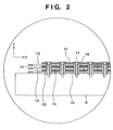
- Fig. 2 is a view showing the coil array of each layer in more detail, in which a portion A of Fig. 1B is enlarged.
- the coil array 10 is formed on the base 9 through an insulating sheet 20.
- the coil array 10 includes a first-layer coil array 11, second-layer coil array 12, third-layer coil array 13, fourth-layer coil array 14, fifth-layer coil array 15, and sixth-layer coil array 16 sequentially from the upper side.
- the substantially elliptic coil of the coil array 11 has straight portions parallel to the Y direction, and is mainly used for driving in the X direction.
- the substantially elliptic coil of the coil array 12 has straight portions parallel to the X direction, and is mainly used for driving in the Y direction.
- the substantially elliptic coil of the coil array 13 has straight portions parallel to the Y direction, and is mainly used for driving in the Z direction.
- the substantially elliptic coil of the coil array 14 has straight portions parallel to the X direction, and is mainly used for driving in the ⁇ Z direction.
- the substantially elliptic coil of the coil array 15 has straight portions parallel to the Y direction, and is mainly used for driving in the ⁇ Y direction.
- the substantially elliptic coil of the coil array 16 has straight portions parallel to the X direction, and is mainly used for driving in the ⁇ X direction.
- Insulating sheets 20 are arranged between the respective coil arrays. The insulating sheets 20 serve to prevent short-circuiting among the coil arrays.
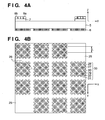
- Figs. 4A and 4B are views showing the movable element unit 1 in detail, in which Fig. 4A is a side view of the movable element unit 1, and Fig. 4B is a bottom view of the movable element unit 1 seen in a vertically upward direction (-Z direction).
- Fig. 4B the front side of the sheet surface coincides with the -Z direction, and the deep side of the sheet surface coincides with the +Z direction.
- the magnet unit 6 is fixed to the lower portion of the top plate 5.
- the magnet unit 6 includes six types of magnets, i.e., a magnet magnetized such that a magnetic flux flows in it in the +Z direction, a magnet magnetized in the -Z direction, and magnets magnetized in directions inclined by 45°, 135°, -135°, and -45°, respectively, with respect to the X direction.
- a magnet magnetized such that a magnetic flux flows in it in the +Z direction a magnet magnetized in the -Z direction
- magnets magnetized in directions inclined by 45°, 135°, -135°, and -45°, respectively, with respect to the X direction are indicated by arrows in the corresponding directions.
- a magnetic flux in the +Z direction is generated near each magnet 27 magnetized in the +Z direction.
- a magnetic flux in the -Z direction is generated near each magnet 28 magnetized in the -Z direction.
- a magnetic flux in the direction of -135° with respect to the X direction is generated near each magnet 29 magnetized in the direction of 45° with respect to the X direction.
- a magnetic flux in the direction of -45° with respect to the X direction is generated near each magnet 30 magnetized in the direction of 135° with respect to the X direction.
- a magnetic flux in the direction of 135° with respect to the X direction is generated near each magnet 31 magnetized in the direction of -45° with respect to the X direction.
- a magnetic flux in the direction of 45° with respect to the X direction is generated near each magnet 32 magnetized in the direction of -135° with respect to the X direction. This is apparent when considering the directions of the magnetic fluxes around a magnet magnetized in a predetermined direction.
- the magnets magnetized in the respective directions are arranged in a so-called Halbach array. A specific arrangement will be described hereinafter.
- the magnets 27 magnetized in the +Z direction align themselves in the X and Y directions at a period L, and in the directions inclined by 45° and -45° with respect to the X direction at a period ⁇ 2 x L.
- Magnets magnetized in the +Z direction and -Z direction alternately align themselves in directions inclined by 45° and -45° with respect to the X direction at every distance ⁇ 2/2 x L.
- Magnets magnetized in the directions inclined by 45° and -135° with respect to the X direction are alternately arranged, in the direction inclined by 45° with respect to the X direction, between magnets magnetized in the +Z direction and magnets magnetized in the -Z direction.
- Magnets magnetized in the directions inclined by -45° and 135° with respect to the X direction are alternately arranged, in the direction of -45° with respect to the X direction, between magnets magnetized in the +Z direction and magnets magnetized in the -Z direction.
- the magnetic fluxes directed to the front side that is, the magnetic fluxes in the -Z direction are reinforced as they are gathered in the four directions (directions inclined by ⁇ 45° and ⁇ 135° with respect to the X direction).
- the magnetic fluxes which run to the deep side of the sheet surface that is, the magnetic fluxes in the +Z direction are reinforced as they are dispersed in the four directions.
- the magnetic fluxes cancel each other, so that the magnetic flux distribution becomes substantially zero.
- the magnets 27 to 32 align themselves in the X and Y directions each at the period L. Therefore, the magnets 27 to 32 are distributed such that their magnetic flux density in the vertical direction and that in the horizontal direction both form substantial sine curves with periods L along the X and Y directions, respectively.
- the magnetic flux density in the vertical direction and that in the horizontal direction are distributed with a shift of distance L/4. Assuming that the distance L is a 360° (2 ⁇ ) phase, the peak position of the magnetic flux density distribution in the vertical direction and that of the magnetic flux density distribution in the horizontal direction are phase-shifted from each other by 90°.
- non-magnet portions 25 where no permanent magnets are provided exist on the two end portions (the upper right corner and lower left corner of the top plate 5) of one diagonal on the lower surface of the top plate 5. Also, three linear non-magnet portions 26 exist in each of the X and Y directions.
- 14 small magnet units 33 each including a total of 33 magnets, i.e., four magnets magnetized in the +Z direction, four magnets magnetized in the -Z direction, nine magnets magnetized in the direction of -45° with respect to the X direction, six magnets magnetized in the direction of 45° with respect to the X direction, four magnets magnetized in the direction of 135° with respect to the X direction, and six magnets magnetized in the direction of -135° with respect to the X direction, are arranged on the lower surface of the top plate 5.
- the magnet unit 6 includes small units in this manner, the movable element unit 1 can be made lightweight. Also, as the magnets are arranged such that they are asymmetric with respect to a straight line parallel to the X or Y direction, driving in the rotational direction is possible.
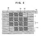
- FIG. 5 is a view of the coil array 12 and top plate 5 seen from the -Z direction.
- the coil array 12 is a layer including substantially elliptic coils each having straight portions in the X direction.
- the distance between the two straight lines (long sides) of each substantially elliptic coil is half the period L, that is, L/2, and adjacent substantially elliptic coils are separate from each other by 3/4 X L.
- L the period L
- an adjacent coil is shifted from it by 270°
- the next adjacent coil is shifted from it by 540° (180°)
- the still next coil is shifted from it by 810° (90°)
- the still next coil has the same phase as 1,080° (0°). This phase pattern is repeated.
- the coils can appear as coils having two types of phases, i.e., 0° and 90°.
- the current direction in every other coil is set in the opposite direction.
- a coil to which the opposite current is supplied is indicated by a "-" (minus) sign. Accordingly, the current flowing to the coils appears to include two phases, i.e., A phase and B phase.
- the -A phase current and -B phase current are determined automatically.
- each of the vertical magnetic flux density and horizontal magnetic flux density has a substantial sine wave distribution with the period L.
- a coil layer including substantially elliptic coils having straight portions parallel to the X direction forces with arbitrary magnitudes can be generated in the ⁇ Y directions or ⁇ Z directions.
- a coil layer (e.g., Fig. 3A) including substantially elliptic coils having straight portions parallel to the Y direction forces with arbitrary magnitudes can be generated in the ⁇ X directions or ⁇ Z directions.
- the magnet unit 6 is not arranged on the entire lower surface of the top plate 5 and has the linear non-magnet portions 26. At the non-magnet portions, when a current is supplied to the coils, no propelling force or levitating force is generated. Thus, current application is controlled so that no current is supplied to the non-magnet portions 26. In other words, current control is performed to supply a current only to coils facing the magnets.
- the number of A or -A phase coils and the number of B or -B phase coils are set to be equal.
- control is performed such that a current having the same phase as that of the magnetic flux density distribution is supplied to the coils, a substantially constant propelling force or levitating force is obtained regardless of the position. This applies when the number of A or -A phase coils and the number of B or -B phase coils are equal.
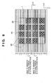
- a method of turning on/off the coils will be described with reference to Figs. 6A and 6B and Figs. 7A and 7B.
- Figs. 6A and 6B are views for explaining energization switching for a coil array that generates the propelling force.
- 14 small magnet units 33 each including 33 magnets are arranged on the lower surface of the top plate 5.
- the coils are turned on/off such that the A or -A phase coils and the B or -B phase coils in the same numbers act on the small magnet units.
- the coils are turned on/off such that the current flows to a total of two coils, i.e., one A or -A phase coil and one B or -B phase coil, of each small magnet unit.
- Figs. 6A and 6B are views aiming at how the movable element unit 1 moves in the +Y direction.
- the movable element unit 1 having moved in the +Y direction reaches the state of Fig. 6A and further moves in the +Y direction to reach the state of Fig. 6B.
- the coils that are turned on are indicated by double lines (the -B phase coils under the movable element unit 1 in Figs. 6A and 6B) and thick solid lines (the A phase coils under the movable element unit 1 in Figs. 6A and 6B), and the coils that are turned off are indicated by solid lines.
- a propelling force proportional to the sine wave amplitude can be generated.
- control is performed such that the currents of the B or -B phase coils the straight portions of which are immediately under the magnets magnetized in the ⁇ Z directions are the maximum, and that the currents of the A or -A phase coils the straight portions of which are just at the middle of the magnets magnetized in the ⁇ Z directions are zero.
- the sine wave current is a current defined as a sin function, a cos function, or a function having a harmonic component.
- the -A and -B phase coils are ON.
- the -A phase coils are turned off and the A phase coils are turned on.
- the B phase coils located on the lower surface of the non-magnet portions 26 are OFF, and coils that are not located on the lower surface of the movable element unit 1 are all OFF regardless of whether they are A, B, -A, or -B phase coils.
- the -B phase coils are turned off, and the B phase coils are turned on.
- the on/off of each coil is switched at the moment the coil reaches the peak of the vertical magnetic flux density distribution (that is, the moment the current value supplied to the coil also reaches the peak and the current values of two adjacent coils having phases shifted by 90° become zero), so that two coils act on each small magnet unit.
- current control is performed in this manner, while suppressing power consumption by a coil that does not contribute to the thrust, propelling forces in the ⁇ Y directions proportional to the instructed value can be generated regardless of the position of the movable element unit 1.
- the on/off of each coil is performed at a position where the current of the coil to be switched becomes zero, fluctuations in the thrust can be decreased.
- Figs. 7A and 7B are views for explaining energization switching for a coil array that generates the levitating force.
- the movable element unit 1 having moved in the +Y direction reaches the state of Fig. 7A and further moves in the +Y direction to reach the state of Fig. 7B.
- the idea of switching is the same as that for the case of Figs. 6A and 6B.
- Energization is switched such that one A or -A phase and one B or -B phase coil act on the small magnet unit. Note that the peak position of the magnetic flux distribution is different from that of Figs. 6A and 6B and accordingly the coil switching position is different from that of Figs. 6A and 6B.
- the current is controlled to zero when the coil straight portions are located just at the middle of a magnet magnetized in the Z direction and a magnet magnetized in the -Z direction. If a levitating force is to be generated, the current is controlled to zero when the coil straight portions are located immediately under the magnets magnetized in the ⁇ Z directions.
- the position to control the current to zero differs, in connection with the relationship between the coil straight portions and the magnets magnetized in the ⁇ Z directions, between the propelling force and levitating force by a L/4 period in the position in the Y-axis direction.
- X-direction driving is mainly performed by the coil array 11 including substantially elliptic coils which are the closest to the magnets and have straight portions parallel to the Y direction.
- Y-direction driving is mainly performed by the coil array 12 adjacent to the coil array 11 and including the substantially elliptic coils which have straight portions parallel to the X direction.
- Z-direction driving is mainly performed by the coil array 13 adjacent to the coil array 12 and including substantially elliptic coils which have straight portions parallel to the Y direction.
- Fig. 8 is a view for explaining generation of a moment about the Z-axis.
- a layer including substantially elliptic coils having straight portions parallel to the X direction of the magnets provided to the movable element unit 1, only those coil portions which face the non-magnet portions 25 are energized, and coil energization is controlled such that propelling forces in opposite directions (forces in the +Y and -Y directions) are generated by these two coil portions. Due to the presence of the non-magnet portions 25, the acting lines of the propelling forces in the opposite directions are shifted in the X direction, so that a moment about the Z-axis can be generated. Specifically, the moment about the Z-axis can be generated by using the coil array 14 shown in Fig. 2.
- the current control method and switching method for the coils are the same as those described above, and a description thereof will be omitted.
- Fig. 9 is a view for explaining generation of a moment about the X-axis.
- a layer including substantially elliptic coils having straight portions parallel to the X direction only the coil portions which face eight small magnet units at the center having no non-magnet portions 25 are driven to generate forces in the ⁇ Z directions.
- Energization to the coils is controlled to generate a force in the Z direction that acts in the opposite directions through a center line G of the movable element as a boundary.
- forces in the opposite Z directions form a moment that rotates the movable element unit 1 about the X-axis.
- the moment about the X-axis can be generated by using the coil array 16 shown in Fig. 2.
- Fig. 10 is a view for explaining generation of a moment about the Y-axis.
- a layer including substantially elliptic coils having straight portions parallel to the Y direction only the coil portions which face eight small magnet units at the center having no non-magnet portions are driven to generate forces in the ⁇ Z directions.
- Energization to the coils is controlled to generate a force in the Z direction that acts in the opposite directions through the center line G of the movable element as a boundary.
- forces in the opposite Z directions form a moment that rotates the movable element unit 1 about the Y-axis.
- the moment about the Y-axis can be generated by using the coil array 15 shown in Fig. 2.
- the forces in the six-axis directions are proportional to the current, and can insulate vibration between the movable element unit and stator unit.
- the movable element unit 1 having the magnet unit 6 arranged asymmetrically with the top plate 5, and the stator unit 2 obtained by fixing to a base a plurality of coil layers each including substantially elliptic coils having straight portions parallel to the X or Y directions the Lorentz forces in directions of six degrees of freedom can be applied to the movable element unit 1 formed of the top plate 5 and magnets.
- a position measuring means (not shown) for measuring the directions of six degrees of freedom and position control is performed such that the movable element unit 1 is located at a desired position
- high accurate position control can be performed.
- the weight of the movable element unit 1 is almost canceled by the attracting force of the permanent magnets 8.
- substantially no Lorentz force in the Z direction need be generated, and only a small current for correcting a small positional shift flows.
- the coils of the stator unit have no magnetic cores, cogging can be decreased. As a result, coil heat generation can be largely decreased.
- bipolar magnets are arranged at the four corners of the top plate 5 of the movable element unit 1.
- Figs. 11A and 11B are views showing a modification in which the stator unit has four coil layers.
- the movable element unit and attracting plate are the same as those of the first embodiment.
- the stator unit has two layers each including substantially elliptic coils having straight portions parallel to the X direction, and two layers each including substantially elliptic coils having straight portions parallel to the Y direction, leading to a total of four layers.
- a layer that generates forces in directions of six degrees of freedom is provided separately.
- the stator unit includes four layers each of which generates forces in directions of two degrees of freedom.
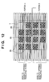
- Fig. 12 is a view for explaining driving in the Y direction and driving in the ⁇ z direction.
- a coil layer e.g., a coil array 42 of Fig. 11B
- a coil layer including substantially elliptic coils having straight portions parallel to the X direction
- only coils that face a movable stage 1 are driven, and the current is controlled such that different translating forces are generated by the upper half (portion U) and lower half (portion D) in Fig. 12 with respect to a line segment extending through the Y-direction center of the movable stage 1.
- the sum of the force generated by the upper half and the force generated by the lower half forms translating forces in the Y direction.
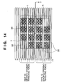
- Fig. 14 is a view for explaining driving in the X direction and driving in the ⁇ z direction.
- a coil layer e.g., a coil array 41 of Fig. 11B
- a coil layer including substantially elliptic coils having straight portions parallel to the Y direction
- only coils that face the movable stage 1 are driven, and the current is controlled such that different translating forces are generated by the right half (portion R) and left half (portion L) in Fig. 14 with respect to a line segment extending through the X-direction center of the movable stage 1.
- the sum of the force generated by the right half and the force generated by the left half forms translating forces in the X direction.
- Fig. 13 is a view for explaining driving in the Z direction and driving in the ⁇ x direction.
- a coil layer e.g., a coil array 44 of Fig. 11B
- a coil layer including substantially elliptic coils having straight portions parallel to the X direction
- only coils that face the movable stage 1 are driven, and the current is controlled such that different Z-direction levitating forces are generated by the upper half (portion U) and lower half (portion D) in Fig. 13 of the movable stage 1.
- the sum of the force in the Z direction generated by the upper half and the force in the Z direction generated by the lower half forms levitating forces to act on the movable element.
- the acting line of the force generated by the upper half and the acting line of the force generated by the lower half are shifted from each other in the Y direction, the difference between the forces generated by the upper and lower halves acts as a moment in the ⁇ x direction.
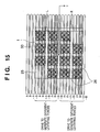
- Fig. 15 is a view for explaining driving in the Z direction and driving in the ⁇ y direction.
- a coil layer e.g., a coil array 43 of Fig. 11B
- a coil layer including substantially elliptic coils having straight portions parallel to the Y direction
- only coils that face the movable stage 1 are driven, and the current is controlled such that different Z-direction levitating forces are generated by the right half (portion R) and left half (portion L) in Fig. 15 of the movable stage 1.
- the sum of the force in the Z direction generated by the right half and the force in the Z direction generated by the left half forms levitating forces to act on the movable stage 1.
- the acting line of the force generated by the right half and the acting line of the force generated by the left half are shifted from each other in the X direction, the difference between the forces generated by the right and left halves acts as a moment in the ⁇ y direction.
- the number of coil layers can be decreased. From another point of view, the coil sectional area per layer can be increased, and accordingly the resistance of the coils is decreased and heat generated by the coils is decreased.
- the number of coil layers is four and six in the above description, the present invention is not limited to them.
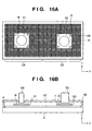
- Figs. 16A and 16B show the second embodiment.
- one movable unit is provided.
- two movable units are provided.
- the arrangement having two movable units in this manner attracts attention recent years as a wafer stage used in an exposure apparatus.
- exposure operation of exposing a pattern onto a wafer and measurement (alignment) operation of measuring the position of the pattern exposed last time are performed simultaneously, an increase in throughput can be expected.
- Fig. 16A is a view of movable stages 51 and 52 seen from the Z-axis direction.
- the two movable stages 51 and 52 can move in a measurement region 54 and exposure region 53, respectively.
- a projection optical unit 55 e.g., a projection lens, which exposes the pattern of the wafer mounted on the movable element is arranged above the exposure region 53.
- a measurement optical unit 56 e.g., an off-axis scope, which measures the position of the exposed pattern is arranged above the measurement region 54.
- a wafer W transported from a transport system (not shown) is mounted on the movable stage 51 located within the measurement region 54.
- the position of the pattern on the mounted wafer which is exposed last time is measured by using the measurement optical unit 56 in the measurement region 54.
- the movable stage 51 subjected to the measuring operation moves to the exposure region 53.
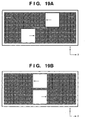
- the movable stage 52 located within the exposure region 53 moves to the measurement region 54 not to come into contact with the movable stage 51 (see Figs. 19A and 19B).
- Exposure operation takes place on the movable stage 51 having moved to the exposure region 53 by using the projection optical unit 55.
- the next wafer W transported from the transport system is mounted on the movable stage 52, having moved to the measurement region 54, in the measurement region 54, and the position of the pattern exposed last time is measured by using the measurement optical unit 56.
- the movable stage 51 where the exposure operation takes place moves to the measurement region 54.
- the wafer W on the movable stage 51 is recovered by a recovery device (not shown), and a new transported wafer is mounted on the movable stage 51.
- the movable stage 52 where the measurement operation has been performed moves to the exposure region 53. After that, the same operations are repeated.
- An attracting plate 57 is arranged above the movable stages 51 and 52 to cover their moving range to cancel the weights of the movable stages 51 and 52.
- the attracting plate 57 has openings at portions where the exposure optical unit 55 and measurement optical unit 56 are provided.
- the attracting plate 57 can be divided into the exposure region 53 and measurement region 54.
- stator unit 58 according to the second embodiment will be described with reference to Figs. 18A and 18B.
- the stator unit 58 has four or six coil layers each including substantially elliptic coils. Note that in the second embodiment, the two movable stages 51 and 52 must be interchangeable between the exposure region 53 and measurement region 54. A mechanism for achieving this will be described hereinafter.
- the layer including the substantially elliptic coils having straight portions parallel to the X direction is halved into left and right portions.
- the two movable stages are located in the exposure region 53 and measurement region 54. Even when the two movable stages are aligned on one straight line parallel to the X direction, the forces in 6-axis directions of each movable stage can be controlled independently. Conversely, if the coil layer is not halved, when the two movable stages are aligned on one straight line parallel to the X direction, the substantially elliptic coils having the straight lines parallel to the X direction are shared between the two movable stages.
- the substantially elliptic coils are divided in the Y direction at a portion in the vicinity of the dividing boundary of the layer, described above, including the substantially elliptic coils having the straight portions parallel to the X direction, that is, at a portion in the vicinity of the boundary of the exposure region 53 and measurement region 54.
- the dividing boundary of the substantially elliptic coils is located on, e.g., a straight line that connects an exposure position and measurement position.
- the movable stages as shown in Figs. 19A and 19B are interchanged.
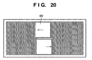
- the two movable stages should not be aligned at an X position outside the dividing boundary. This is because if the movable stages 51 and 52 are aligned on a substantially elliptic coil as shown in Fig. 20, they cannot be controlled independently.
- the divisional region may be formed larger than the X-direction width of each movable stage, or the two movable stages are controlled such that they can meet each other with a rotationally symmetric positional relationship with respect to the X-direction center of the divisional region. (Modification of Attracting plate)
- Figs. 17A to 17C show modifications of the attracting plate. More specifically, in Figs. 17A to 17C, the attracting plate 57 of Fig. 16B is modified to have a stacked layer structure. In Figs. 17B and 17C, an attracting plate 67 is formed by stacking in the X direction thin plates extending along a Y-Z plane, and is arranged through supports. The effect of the stacked layer structure will be described hereinafter.
- the attracting plate 57 is made of a magnetic material, generally a conductor, to generate an attracting force together with the permanent magnets 8 on the two movable stages.
- magnetic fluxes generated by the permanent magnets pass through the attracting plate 57.
- an eddy current is undesirably generated in the attracting plate 57 in an attempt to cancel a change in magnetic fluxes.
- the eddy current exerts a viscous force to the movable stages in the horizontal direction to increase heat generation by the coils for driving.
- the attracting plate 67 has a stacked layer structure including thin plates, so that the electrical resistance is equivalently increased with respect to the eddy current which is to flow, thus decreasing the value of the eddy current. Then, the viscous force decreases to decrease an increase in coil heat generation. The pulsation component of the force characteristics is also decreased to improve the control accuracy.
- the attracting plate 67 is formed by stacking in the X direction the thin plates extending along the Y-Z plane.
- the permanent magnets on each movable stage are preferably arranged such that their N and S poles are arrayed in the Y direction as shown in Fig. 17B.
- the magnetic flux obtained with this arrangement mainly includes only a Z-direction component and Y-direction component.
- the attracting plate 67 is formed by stacking the thin plates extending along the Y-Z plane, a resistance against the eddy current about the Z-axis and a resistance against the eddy current about the Y-axis are large. In other words, the structure of Fig. 17B can effectively decrease an eddy current generated when the movable stage moves in the Y direction.
- the attracting plate 67 can be formed by stacking in the Y direction thin plates extending in the X-Z direction.
- the permanent magnets 8 on the movable stage are arranged such that their N and S poles are arrayed in the Y direction, the eddy current which is generated when the movable stage moves in the X direction by the above reason can be decreased effectively.
- Fig. 17C shows a structure in which a nonmagnetic and/or insulating cover 68 is provided under the stacked attracting plate 67.
- the cover 68 is provided to prevent attraction of the permanent magnets 8 and attracting plate 67 to each other.
- the cover 68 is made of a nonmagnetic material, a situation magnetically equivalent to air is created, so that an adverse influence of magnetism is eliminated.
- the cover 68 is made of an insulator, an adverse influence of the eddy current is suppressed.
- a large gap may be designed between the permanent magnets 8 on the movable stage and the attracting plate 67, so that the movable stage is not sensitive to fluctuations of the attracting plate 68 in the Z direction. If a large gap cannot be formed due to some reason, a cover 68 slightly thinner than the gap is desirably provided between the permanent magnets 8 and attracting plate 67. With this structure, even if control becomes impossible and the permanent magnets 8 are attracted to the attracting plate 67, as the difference between the weight of the movable stage and the attracting force is small, the permanent magnets 8 can be restored by supplying a current to the stationary unit.
- Thin plates or tapes having a small coefficient of friction can be provided on the permanent magnets 8, or a rolling means such as a cam follower may be provided between the movable stage and the attracting plate 67. Then, when the permanent magnets 8 are attracted to the attracting plate 67, the permanent magnets 8 and cover 68 do not come into direct contact with each other, so that damage or the like to the permanent magnets 8 can be prevented.
- a current is supplied to the coils of the stator unit 2 while the permanent magnets 8 are kept attracted to the cover 68, the movable stage can be moved in the horizontal direction and brought to a desired position.
- the examples of the attracting plates having the stacked layer structure and covers described above are not limited to a case wherein two movable stages are provided but can also be naturally applied to a case wherein one movable stage is provided, and to any other modification.
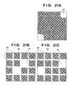
- Figs. 21A to 21C show modifications of the arrangement of the permanent magnets of the magnet unit provided under the movable stage. These modifications can be applied to both the first and second embodiments.
- Fig. 21A shows a structure in which the linear non-magnet portions 26 in the first embodiment are eliminated and non-magnet portions 25 are provided only to the two ends (upper right corner and lower left corner) of one diagonal.
- the control method is basically the same as that of the first embodiment and a description thereof will accordingly be omitted.
- the magnets in the first embodiment are divided into the small magnet units 33 each including 33 magnets. In this case, the magnetic flux decreases at the edge portion of each small magnet unit 33.
- the edge portions of the small magnet units 33 can be eliminated. As a result, a decrease in magnetic flux can be eliminated to increase the thrust and the uniformity of the thrust.
- Fig. 21B shows a structure in which the non-magnet portions 25 of the first embodiment are arranged inside the movable stage. Even with this structure, in a certain coil layer, currents in the opposite directions may be supplied to the coil portions facing two non-magnet portions to generate translating forces in the opposite directions, in the same manner as in the first embodiment. Alternatively, in a certain coil layer, the translating forces may be controlled separately between the upper and lower portions or the left and right portions of the movable stage, in the same manner as described above (the modification in which the stator unit includes four coil layers). Then, a moment in the wz direction can be generated.
- non-magnet portions 25 can be formed at the positions shown in Fig. 21C.
- the permanent magnets are arranged on the lower surface of the movable stage such that they are asymmetric with respect to a straight line parallel to the X direction and/or to a straight line parallel to a straight line parallel to the Y direction.
- Figs. 22A and 22B are views for explaining the structure of a coil cooling system.
- coil heat generation is an issue.
- the following cooling system is desirably provided.
- Fig. 22A shows a structure in which the coil is cooled by a refrigerant directly
- Fig. 22B shows a structure in which the coil is cooled by a refrigerant indirectly.
- the coil of a stator unit 70 is covered by a partition 71.
- the partition 71 may be integral with a base 72, or may be fixed to the base 72.
- the partition 71 has a supply port 73 for supplying a refrigerant and a discharge port 74 for discharging the refrigerant.
- a refrigerant such as Fluorinert or pure water is supplied inside and discharged outside the partition 71, so that the temperature-controlled refrigerant is circulated by a circulating system (not shown). With this structure, the temperature increase of the coil can be decreased effectively.
- a partition 71 which covers the coil is filled with a heat conductive material 75 having high thermal conductivity.
- a refrigerant is circulated in a flow channel 76 such as a cooling pipe arranged in a base 72 by a circulating system (not shown). With this structure, the base 72 is cooled by the refrigerant. Heat is conducted from the base 72 to the heat conductive material 75 to cool the coil indirectly by the heat conductive material 75.
- the control accuracy of the coil temperature is more or less lower than that in the structure of Fig. 22A, as the coil and refrigerant do not come into direct contact with each other, the measure for insulation can be simple, and no countermeasure is necessary against leakage of the refrigerant.
- the partition 71 does not receive the internal pressure of the refrigerant, the partition 71 can be made thin.
- the coil can be cooled to be deprived of heat. Therefore, a larger current can be supplied to the coil, and the adverse influence that the ambient temperature around the coil imposes on the measurement accuracy can be decreased.
- Fig. 23 shows an example in which the aligning apparatus (stage device) described above is employed in a vacuum atmosphere.
- the aligning apparatus is applied to an exposure apparatus which uses EUV (Extreme Ultra Violet) light as exposure light.
- EUV Extreme Ultra Violet
- the EUV exposure apparatus prints a reticle pattern onto a wafer by using light having as very a short wavelength of about 13 nm.
- short-wavelength light such as EUV light
- a vacuum atmosphere is needed to prevent attenuation of the energy.
- a high-vacuum atmosphere is needed around the optical system.
- a stage device as a aligning apparatus is set inside a partition 90 (vacuum chamber) having an interior filled with a vacuum atmosphere.
- the structure and operation of a movable stage 1 and stator unit 2 can be basically the same as those of the embodiments and modifications described above, and a detailed description thereof will accordingly be omitted.
- a magnet unit (not shown) for generating a driving force is arranged on the lower surface of the movable stage 1.
- Permanent magnets 8 for generating an attracting force and a wafer chuck (not shown) for holding a wafer W are arranged on the upper surface of the movable stage 1.
- the upper surface of the wafer W and the upper surfaces of the attracting permanent magnets are located within one plane.
- a level plate 88 is provided among the wafer W, wafer chuck, and permanent magnets 8 to make a continuous surface from the upper surface of the wafer W to the upper surfaces of the attracting permanent magnets 8.
- An attracting plate 84 arranged above the movable stage 1 serves as a so-called differential exhaust plate.
- the vacuum chamber has three regions (V 1 , V 2 , and V 3 ) having different vacuum degrees.
- the space where the movable stage 1 and stator unit 2 are arranged has the lowest vacuum degree among the three spaces (this space will be called a vacuum region V 3 ).
- the space around the EUV optical system has the next lowest vacuum degree (this space will be called a vacuum region V 2 ).
- the interior of the EUV optical system has the highest vacuum degree (this space will be called a vacuum region V 1 ). This is due to the following reason.
- the EUV optical system includes a plurality of reflection mirrors 82. If a little water or carbon exists in the space where the reflection mirrors 82 are present, chemical compounds form on the surfaces of the mirrors to decrease the reflectance. To prevent this, the space where the EUV optical system is arranged requires a high vacuum. The spaces V 1 and V 2 cannot be completely partitioned by a wall because the EUV optical system extends through them.
- the differential exhaust plate 84 as shown in Fig. 23 is provided to face the upper surface of the movable stage 1 through a small gap G.
- the differential exhaust plate 84 also serves as the attracting plate (described above) and is made of a magnetic material.
- the differential exhaust plate 84 can have (incorporate) an attracting plate and nonmagnetic or insulating cover. In this case, apart from the small gap G for differential exhaust between the movable stage 1 and differential exhaust plate 84, a large magnetic gap is present between the movable stage 1 and differential exhaust plate 84.
- a cooling pipe 85 is arranged in the differential exhaust plate 84 to adjust it to a desired temperature.
- heat transfer is small and an energy received from exposure light is accumulated.
- the temperatures of the wafer W, chuck, and top plate can be controlled to prevent their deformation or the like.
- the differential exhaust plate 84 serves not only as the attracting plate but also a radiation cooling plate.
- the attracting plate 84 incorporates a cover, and a large magnetic gap is designed between the attracting plate 84 and the permanent magnets 8 on the movable stage 1.
- the upper surfaces of the permanent magnets 8 can be lowered from the upper surface of the wafer W by about the magnetic gap, so that a cover having a thickness almost equal to the magnetic gap can be arranged on the permanent magnets 8. If the cover is formed as a level plate to form one surface continuous to the upper surface of the wafer W, the structure of the level plate becomes simple.
- the aligning apparatus described in the first or second embodiment can be suitably used as an exposure apparatus in general.
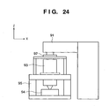
- a general exposure apparatus will be briefly described with reference to Fig. 24.
- the exposure apparatus is used to manufacture devices having fine patterns, e.g., a semiconductor device such as a semiconductor integrated circuit, a micromachine, and a thin film magnetic head.
- Exposure light (this is a generic term for visible light, ultraviolet light, EUV light, X-rays, an electron beam, a charged particle beam, or the like) serving as an exposure energy from an illumination system unit 91 through a reticle as an original irradiates a semiconductor wafer W as a substrate through a projection lens 93 (this is a generic term for a dioptric lens, reflecting lens, cata-dioptric lens system, charged particle lens, or the like) serving as a projection system to form a desired pattern on a substrate mounted on a wafer stage 94.
- the exposure apparatus requires exposure in a vacuum atmosphere.
- a wafer (object) as a substrate is held on a chuck mounted on the wafer stage 94.
- the pattern of the reticle as the original mounted on a reticle stage 92 is transferred onto the respective regions on the wafer by the illumination system unit 91 in accordance with step & repeat or step & scan.
- the aligning apparatus described in the first or second embodiment is used as the wafer stage 94 or reticle stage 92.
- the attracting plate has an opening through which the illumination system unit 91 or projection lens 93 is to extend.
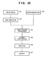
- Fig. 25 is a flowchart showing the flow of the entire semiconductor device manufacturing process.
- step 1 circuit design
- step 2 mask fabrication
- a mask is fabricated on the basis of the designed circuit pattern.
- step 3 wafer manufacture
- step 4 wafer process
- step 5 wafer process
- step 5 assembly process
- step 6 inspections including operation check test and durability test of the semiconductor device fabricated in step 5 are performed.
- a semiconductor device is finished with these processes and delivered in step 7.
- the wafer process of the above step 4 includes the following steps, i.e., an oxidation step of oxidizing the surface of the wafer, a CVD step of forming an insulating film on the wafer surface, an electrode formation step of forming an electrode on the wafer by deposition, an ion implantation step of implanting ions in the wafer, a resist process step of applying a photosensitive agent to the wafer, an exposure step of transferring the circuit pattern to the wafer after the resist process step by the exposure apparatus described above, a developing step of developing the wafer exposed in the exposure step, an etching step of removing portions other than the resist image developed in the developing step, and a resist removal step of removing any unnecessary resist after etching. These steps are repeated to form multiple circuit patterns on the wafer.
Landscapes
- Physics & Mathematics (AREA)
- Engineering & Computer Science (AREA)
- General Physics & Mathematics (AREA)
- Chemical & Material Sciences (AREA)
- Combustion & Propulsion (AREA)
- Electromagnetism (AREA)
- Power Engineering (AREA)
- Linear Motors (AREA)
- Exposure And Positioning Against Photoresist Photosensitive Materials (AREA)
- Container, Conveyance, Adherence, Positioning, Of Wafer (AREA)
- Exposure Of Semiconductors, Excluding Electron Or Ion Beam Exposure (AREA)
- Motor Or Generator Cooling System (AREA)
Applications Claiming Priority (2)
| Application Number | Priority Date | Filing Date | Title |
|---|---|---|---|
| JP2004059162 | 2004-03-03 | ||
| JP2004059162A JP2005253179A (ja) | 2004-03-03 | 2004-03-03 | 位置決め装置、露光装置およびデバイス製造方法 |
Publications (2)
| Publication Number | Publication Date |
|---|---|
| EP1574906A2 true EP1574906A2 (de) | 2005-09-14 |
| EP1574906A3 EP1574906A3 (de) | 2009-10-28 |
Family
ID=34824509
Family Applications (1)
| Application Number | Title | Priority Date | Filing Date |
|---|---|---|---|
| EP05251254A Withdrawn EP1574906A3 (de) | 2004-03-03 | 2005-03-02 | Vorrichtung zum Ausrichten, Belichtungsapparat, und Verfahren zur Herstellung einer Vorrichtung |
Country Status (3)
| Country | Link |
|---|---|
| US (2) | US7075197B2 (de) |
| EP (1) | EP1574906A3 (de) |
| JP (1) | JP2005253179A (de) |
Families Citing this family (32)
| Publication number | Priority date | Publication date | Assignee | Title |
|---|---|---|---|---|
| JP2005253179A (ja) * | 2004-03-03 | 2005-09-15 | Canon Inc | 位置決め装置、露光装置およびデバイス製造方法 |
| JP2005294468A (ja) * | 2004-03-31 | 2005-10-20 | Canon Inc | 位置決め装置、露光装置及びデバイス製造方法 |
| JP4566697B2 (ja) * | 2004-11-08 | 2010-10-20 | キヤノン株式会社 | 位置決め装置およびそれを用いた露光装置、デバイス製造方法 |
| JP2007068256A (ja) * | 2005-08-29 | 2007-03-15 | Canon Inc | ステージ装置の制御方法 |
| TWI285305B (en) * | 2005-11-07 | 2007-08-11 | High Tech Comp Corp | Auto-aligning and connecting structure between electronic device and accessory |
| KR100726711B1 (ko) * | 2005-12-30 | 2007-06-12 | 한국전기연구원 | 자기부상방식의 대면적 스테이지 장치 |
| JP2007312516A (ja) * | 2006-05-18 | 2007-11-29 | Canon Inc | 駆動装置、露光装置及びデバイス製造方法 |
| US20080024749A1 (en) * | 2006-05-18 | 2008-01-31 | Nikon Corporation | Low mass six degree of freedom stage for lithography tools |
| JP2008004647A (ja) * | 2006-06-20 | 2008-01-10 | Canon Inc | 位置決め装置、露光装置及びデバイスの製造方法 |
| US7592760B2 (en) * | 2006-09-11 | 2009-09-22 | Asml Netherlands B.V. | Lithographic apparatus and device manufacturing method |
| JP4702313B2 (ja) * | 2007-03-22 | 2011-06-15 | ウシオ電機株式会社 | ステージ装置 |
| WO2009003186A1 (en) | 2007-06-27 | 2008-12-31 | Brooks Automation, Inc. | Multiple dimension position sensor |
| US8283813B2 (en) | 2007-06-27 | 2012-10-09 | Brooks Automation, Inc. | Robot drive with magnetic spindle bearings |
| JP5421255B2 (ja) | 2007-06-27 | 2014-02-19 | ブルックス オートメーション インコーポレイテッド | 揚上機能および低コギングの特性を伴うモータ固定子 |
| US9752615B2 (en) | 2007-06-27 | 2017-09-05 | Brooks Automation, Inc. | Reduced-complexity self-bearing brushless DC motor |
| US8823294B2 (en) | 2007-06-27 | 2014-09-02 | Brooks Automation, Inc. | Commutation of an electromagnetic propulsion and guidance system |
| KR101532060B1 (ko) | 2007-06-27 | 2015-06-26 | 브룩스 오토메이션 인코퍼레이티드 | 셀프 베어링 모터를 위한 위치 피드백 |
| KR20100056468A (ko) | 2007-07-17 | 2010-05-27 | 브룩스 오토메이션 인코퍼레이티드 | 챔버 벽들에 일체화된 모터들을 갖는 기판 처리 장치 |
| JP2009253090A (ja) | 2008-04-08 | 2009-10-29 | Canon Inc | 位置決めステージ装置、露光装置およびデバイス製造方法 |
| CN101978585B (zh) * | 2008-04-18 | 2013-08-07 | 株式会社安川电机 | 多自由度传动装置以及载物台装置 |
| JP5481064B2 (ja) * | 2008-12-25 | 2014-04-23 | Thk株式会社 | リニアモータ |
| US7808133B1 (en) * | 2009-04-21 | 2010-10-05 | Asm Assembly Automation Ltd. | Dual-axis planar motor providing force constant and thermal stability |
| US8593016B2 (en) * | 2010-12-03 | 2013-11-26 | Sri International | Levitated micro-manipulator system |
| EP2759047B1 (de) | 2011-10-27 | 2022-03-16 | The University Of British Columbia | Verschiebungsvorrichtungen und verfahren zur herstellung, ihre verwendung und steuerung |
| US20130271738A1 (en) * | 2012-04-13 | 2013-10-17 | Nikon Corporation | Movable body apparatus, exposure apparatus, and device manufacturing method |
| CN103066894B (zh) * | 2012-12-12 | 2015-05-20 | 清华大学 | 一种六自由度磁悬浮工件台 |
| CN105452812B (zh) | 2013-08-06 | 2019-04-30 | 不列颠哥伦比亚大学 | 移位装置以及用于检测和估计与其相关联的运动的方法和设备 |
| WO2015179962A1 (en) * | 2014-05-30 | 2015-12-03 | The University Of British Columbia | Displacement devices and methods for fabrication, use and control of same |
| EP3152822B1 (de) | 2014-06-07 | 2019-08-07 | The University Of British Columbia | Verfahren und systeme zur kontrollierten bewegung von mehrerer beweglicher stufen in einer verdrängervorrichtung |
| WO2015188281A1 (en) | 2014-06-14 | 2015-12-17 | The University Of British Columbia | Displacement devices, moveable stages for displacement devices and methods for fabrication, use and control of same |
| CN107852082B (zh) | 2015-07-06 | 2020-05-26 | 不列颠哥伦比亚大学 | 用于在位移装置上可控制地移动一个或多个可移动台的方法和系统 |
| US20250118602A1 (en) * | 2023-10-10 | 2025-04-10 | Kla Corporation | Metrology system with twin planar motor stage |
Citations (2)
| Publication number | Priority date | Publication date | Assignee | Title |
|---|---|---|---|---|
| US6144119A (en) * | 1999-06-18 | 2000-11-07 | Nikon Corporation | Planar electric motor with dual coil and magnet arrays |
| US20020149270A1 (en) * | 2001-04-12 | 2002-10-17 | Hazelton Andrew J. | Planar electric motor with two sided magnet array |
Family Cites Families (24)
| Publication number | Priority date | Publication date | Assignee | Title |
|---|---|---|---|---|
| JPS58173843A (ja) * | 1982-04-07 | 1983-10-12 | Telmec Co Ltd | 平面駆動装置 |
| US5196745A (en) * | 1991-08-16 | 1993-03-23 | Massachusetts Institute Of Technology | Magnetic positioning device |
| JPH086642A (ja) | 1994-06-20 | 1996-01-12 | Brother Ind Ltd | 平面モータの位置決め装置 |
| FR2728092A1 (fr) * | 1994-12-07 | 1996-06-14 | Philips Electronique Lab | Procede pour le decodage d'images comprimees |
| US5925956A (en) * | 1995-06-30 | 1999-07-20 | Nikon Corporation | Stage construction incorporating magnetically levitated movable stage |
| US5780943A (en) * | 1996-04-04 | 1998-07-14 | Nikon Corporation | Exposure apparatus and method |
| JPH10521A (ja) * | 1996-06-07 | 1998-01-06 | Nikon Corp | 支持装置 |
| US5886432A (en) * | 1997-04-28 | 1999-03-23 | Ultratech Stepper, Inc. | Magnetically-positioned X-Y stage having six-degrees of freedom |
| EP1017155A4 (de) * | 1997-08-21 | 2007-05-02 | Nikon Corp | Positioniervorrichtung, antriebseinheit, und ausrichtvorrichtung mit einer solchen positioniervorrichtung |
| JPH1169764A (ja) | 1997-08-21 | 1999-03-09 | Nikon Corp | 位置決め装置及び該装置を備えた露光装置 |
| US6188147B1 (en) * | 1998-10-02 | 2001-02-13 | Nikon Corporation | Wedge and transverse magnet arrays |
| JP4619594B2 (ja) * | 1999-06-21 | 2011-01-26 | エスアールアイ インターナショナル | 摩擦のない輸送装置および方法 |
| TWI248718B (en) * | 1999-09-02 | 2006-02-01 | Koninkl Philips Electronics Nv | Displacement device |
| JP2001118773A (ja) * | 1999-10-18 | 2001-04-27 | Nikon Corp | ステージ装置及び露光装置 |
| JP2001217183A (ja) * | 2000-02-04 | 2001-08-10 | Nikon Corp | モータ装置、ステージ装置、露光装置及びデバイス製造方法 |
| US6452292B1 (en) * | 2000-06-26 | 2002-09-17 | Nikon Corporation | Planar motor with linear coil arrays |
| US6445093B1 (en) * | 2000-06-26 | 2002-09-03 | Nikon Corporation | Planar motor with linear coil arrays |
| EP1189018B1 (de) * | 2000-09-15 | 2009-02-25 | Vistec Electron Beam GmbH | Sechsachsiges Positioniersystem mit magnetfeldfreiem Raum |
| TWI245482B (en) * | 2000-11-21 | 2005-12-11 | Yaskawa Electric Corp | Linear motor |
| DE10211892A1 (de) * | 2001-03-19 | 2002-12-05 | Canon Kk | Linearer Schrittmotor, Objektträgervorrichtung und Belichtungsvorrichtung |
| KR100432243B1 (ko) * | 2001-07-06 | 2004-05-22 | 삼익Lms주식회사 | 방열구조를 가진 리니어모터 |
| EP1333468B1 (de) * | 2002-01-22 | 2010-05-26 | Ebara Corporation | Trägerplattevorrichtung |
| EP1378986A1 (de) * | 2002-07-02 | 2004-01-07 | Nti Ag | Konstantkraftgeber |
| JP2005253179A (ja) * | 2004-03-03 | 2005-09-15 | Canon Inc | 位置決め装置、露光装置およびデバイス製造方法 |
-
2004
- 2004-03-03 JP JP2004059162A patent/JP2005253179A/ja not_active Withdrawn
-
2005
- 2005-03-02 US US11/068,784 patent/US7075197B2/en not_active Expired - Fee Related
- 2005-03-02 EP EP05251254A patent/EP1574906A3/de not_active Withdrawn
-
2006
- 2006-05-02 US US11/415,175 patent/US7547998B2/en not_active Expired - Fee Related
Patent Citations (2)
| Publication number | Priority date | Publication date | Assignee | Title |
|---|---|---|---|---|
| US6144119A (en) * | 1999-06-18 | 2000-11-07 | Nikon Corporation | Planar electric motor with dual coil and magnet arrays |
| US20020149270A1 (en) * | 2001-04-12 | 2002-10-17 | Hazelton Andrew J. | Planar electric motor with two sided magnet array |
Also Published As
| Publication number | Publication date |
|---|---|
| US20060202568A1 (en) | 2006-09-14 |
| EP1574906A3 (de) | 2009-10-28 |
| JP2005253179A (ja) | 2005-09-15 |
| US20050194843A1 (en) | 2005-09-08 |
| US7547998B2 (en) | 2009-06-16 |
| US7075197B2 (en) | 2006-07-11 |
Similar Documents
| Publication | Publication Date | Title |
|---|---|---|
| US7075197B2 (en) | Aligning apparatus, exposure apparatus, and device manufacturing method | |
| US7227284B2 (en) | Alignment apparatus and exposure apparatus using the same | |
| US6323567B1 (en) | Circulating system for shaft-type linear motors | |
| US8212435B2 (en) | High efficiency voice coil motor | |
| US20100167556A1 (en) | Three degree of movement mover and method for controlling a three degree of movement mover | |
| JP4639517B2 (ja) | ステージ装置、リソグラフィーシステム、位置決め方法、及びステージ装置の駆動方法 | |
| JP4352445B2 (ja) | 平面モータ装置、ステージ装置、露光装置及びその製造方法、並びにデバイス及びその製造方法 | |
| US7348695B2 (en) | Linear motor, moving stage system, exposure apparatus, and device manufacturing method | |
| JPWO1999048192A1 (ja) | 平面モータ装置、ステージ装置、露光装置及びその製造方法、並びにデバイス及びその製造方法 | |
| US7508099B2 (en) | Driving apparatus, exposure apparatus, and device manufacturing method | |
| US7768156B2 (en) | Coil support unit, motor and exposure apparatus using the same, and device manufacturing method | |
| US20040245861A1 (en) | Linear motor, stage device having this linear motor, exposure device, and device manufacturing method | |
| JP3278380B2 (ja) | リニアモータ | |
| JP4702958B2 (ja) | 位置決め装置 | |
| JP2005295762A (ja) | ステージ装置および露光装置 | |
| US20050174551A1 (en) | Position control and heat dissipation for photolithography systems | |
| JP3592292B2 (ja) | リニアモータを有するステージ装置、露光装置 | |
| US20060232145A1 (en) | System for cooling motors | |
| JP2004031673A (ja) | リニアモータ装置及びステージ装置並びに露光装置 | |
| JP3944198B2 (ja) | ステージ装置、露光装置及びデバイス製造方法 |
Legal Events
| Date | Code | Title | Description |
|---|---|---|---|
| PUAI | Public reference made under article 153(3) epc to a published international application that has entered the european phase |
Free format text: ORIGINAL CODE: 0009012 |
|
| AK | Designated contracting states |
Kind code of ref document: A2 Designated state(s): AT BE BG CH CY CZ DE DK EE ES FI FR GB GR HU IE IS IT LI LT LU MC NL PL PT RO SE SI SK TR |
|
| AX | Request for extension of the european patent |
Extension state: AL BA HR LV MK YU |
|
| PUAL | Search report despatched |
Free format text: ORIGINAL CODE: 0009013 |
|
| AK | Designated contracting states |
Kind code of ref document: A3 Designated state(s): AT BE BG CH CY CZ DE DK EE ES FI FR GB GR HU IE IS IT LI LT LU MC NL PL PT RO SE SI SK TR |
|
| AX | Request for extension of the european patent |
Extension state: AL BA HR LV MK YU |
|
| RIC1 | Information provided on ipc code assigned before grant |
Ipc: H02N 15/00 20060101ALI20090918BHEP Ipc: H01L 21/68 20060101ALI20090918BHEP Ipc: G03F 7/20 20060101AFI20050623BHEP |
|
| 17P | Request for examination filed |
Effective date: 20100428 |
|
| AKX | Designation fees paid |
Designated state(s): DE NL |
|
| 17Q | First examination report despatched |
Effective date: 20130308 |
|
| STAA | Information on the status of an ep patent application or granted ep patent |
Free format text: STATUS: THE APPLICATION HAS BEEN WITHDRAWN |
|
| 18W | Application withdrawn |
Effective date: 20130710 |