EP1574342B1 - Mehrfach-Funktions-Gerät, Drucker und Farbstoffzufuhrvorrichtung dafür - Google Patents
Mehrfach-Funktions-Gerät, Drucker und Farbstoffzufuhrvorrichtung dafür Download PDFInfo
- Publication number
- EP1574342B1 EP1574342B1 EP05251385A EP05251385A EP1574342B1 EP 1574342 B1 EP1574342 B1 EP 1574342B1 EP 05251385 A EP05251385 A EP 05251385A EP 05251385 A EP05251385 A EP 05251385A EP 1574342 B1 EP1574342 B1 EP 1574342B1
- Authority
- EP
- European Patent Office
- Prior art keywords
- ink
- cartridge
- supply structure
- structure according
- ink cartridge
- Prior art date
- Legal status (The legal status is an assumption and is not a legal conclusion. Google has not performed a legal analysis and makes no representation as to the accuracy of the status listed.)
- Not-in-force
Links
- 230000000153 supplemental effect Effects 0.000 claims abstract description 9
- 230000013011 mating Effects 0.000 claims abstract 3
- 238000003466 welding Methods 0.000 claims description 21
- 239000002985 plastic film Substances 0.000 claims description 14
- 238000011176 pooling Methods 0.000 claims description 11
- 230000002093 peripheral effect Effects 0.000 claims description 4
- 230000000717 retained effect Effects 0.000 claims description 2
- 239000007788 liquid Substances 0.000 abstract description 5
- 239000006260 foam Substances 0.000 description 18
- 238000012856 packing Methods 0.000 description 10
- 238000004891 communication Methods 0.000 description 9
- 238000007639 printing Methods 0.000 description 9
- 206010019133 Hangover Diseases 0.000 description 4
- 238000000034 method Methods 0.000 description 3
- 238000003825 pressing Methods 0.000 description 3
- 230000009969 flowable effect Effects 0.000 description 2
- 230000005499 meniscus Effects 0.000 description 2
- 239000002184 metal Substances 0.000 description 2
- 229920005989 resin Polymers 0.000 description 2
- 239000011347 resin Substances 0.000 description 2
- 229920003002 synthetic resin Polymers 0.000 description 2
- 239000000057 synthetic resin Substances 0.000 description 2
- JOYRKODLDBILNP-UHFFFAOYSA-N Ethyl urethane Chemical compound CCOC(N)=O JOYRKODLDBILNP-UHFFFAOYSA-N 0.000 description 1
- 238000013459 approach Methods 0.000 description 1
- 238000005452 bending Methods 0.000 description 1
- 230000005540 biological transmission Effects 0.000 description 1
- 238000011109 contamination Methods 0.000 description 1
- 238000013500 data storage Methods 0.000 description 1
- 230000003111 delayed effect Effects 0.000 description 1
- 239000006185 dispersion Substances 0.000 description 1
- 238000001035 drying Methods 0.000 description 1
- 238000010438 heat treatment Methods 0.000 description 1
- 238000001746 injection moulding Methods 0.000 description 1
- 238000004519 manufacturing process Methods 0.000 description 1
- 239000000463 material Substances 0.000 description 1
- 239000000155 melt Substances 0.000 description 1
- 238000002844 melting Methods 0.000 description 1
- 230000008018 melting Effects 0.000 description 1
- 238000010137 moulding (plastic) Methods 0.000 description 1
- 238000005192 partition Methods 0.000 description 1
- 230000000149 penetrating effect Effects 0.000 description 1
- 230000035699 permeability Effects 0.000 description 1
- 239000004033 plastic Substances 0.000 description 1
- 229920006255 plastic film Polymers 0.000 description 1
- 238000009834 vaporization Methods 0.000 description 1
- 230000008016 vaporization Effects 0.000 description 1
Images


Classifications
-
- B—PERFORMING OPERATIONS; TRANSPORTING
- B41—PRINTING; LINING MACHINES; TYPEWRITERS; STAMPS
- B41J—TYPEWRITERS; SELECTIVE PRINTING MECHANISMS, i.e. MECHANISMS PRINTING OTHERWISE THAN FROM A FORME; CORRECTION OF TYPOGRAPHICAL ERRORS
- B41J2/00—Typewriters or selective printing mechanisms characterised by the printing or marking process for which they are designed
- B41J2/005—Typewriters or selective printing mechanisms characterised by the printing or marking process for which they are designed characterised by bringing liquid or particles selectively into contact with a printing material
- B41J2/01—Ink jet
- B41J2/17—Ink jet characterised by ink handling
- B41J2/175—Ink supply systems ; Circuit parts therefor
- B41J2/17503—Ink cartridges
- B41J2/1752—Mounting within the printer
Definitions
- the present invention relates to an ink supply structure for use in a printer or multi function device where ink is supplied from an ink cartridge to a recoding portion.
- an ink cartridge is disposed on an ink jet head such that the ink printer may be large in height.
- an ink cartridge may be separately disposed from an ink jet head (See JP-A-2001-130020 , FIG. 3 ).
- an ink cartridge holder is disposed on a front-left side portion of the printer main body.
- the ink cartridge holder is opened forwardly to house the ink cartridge from the opening.
- a rod-like ink outlet port connectable to an ink cartridge is disposed at a back-face wall of the ink cartridge holder.
- a tube path connecting between the inkjet head and the ink outlet port is disposed on a back side of the back-face wall.
- EP 1 164 025 A upon which the precharacterising portion of appended claim 1 is based describes an ink cartridge in which on one surface of a cartridge case, there are provided a positioning means used in case that the ink cartridge is attached to a recording apparatus, an ink outlet port from an ink pack, an inlet port of the pressurized air and a connection terminal of a circuit board having a data storage means that stores ink information of the cartridge therein, and an inkjet recording apparatus provided with its ink cartridge are provided.
- the ink cartridge of this mode since the cartridge is exactly positioned and fixed to a holder three-dimensionally by the positioning means, mechanical positional adjustment and electrical connection can be exactly performed, so that operation reliability of the recording apparatus can be improved.
- connection terminal of the board in a state where the cartridge has been mounted on the recording apparatus by the positioning means, the connection terminal of the board is located at the upper portion of the ink outlet port.
- the connection terminal can be prevented from being stained with the ink.
- the present invention is based on the above-problem. It is an object of the invention to provide a multi function device, printer and an ink supply structure therefore, which can downsize.
- an ink supply structure as defined in appended claim 1.
- the ink flowing out from the ink cartridge is transporting to an ink transporting tube at the recording portion via a cartridge connecting portion, an ink flow path and a tube connecting portion.
- the ink flow path is disposed between the cartridge connecting portion and the ink transporting tube, so that an extracting direction of the ink transporting tube can be arbitrarily set.
- Fig. 1 is a perspective view showing a multi function device applied to this embodiment.
- the multi function device 10 has a communication function in addition to a facsimile function, and further has a scanner function and a printer function when connected to a personal computer or the like.
- the near side of Fig. 1 is set as a front side, and the right-and-left direction is defined on the basis of the orientation of Fig. 1 .
- the multi function device 10 has a flat bed type scanner device 130 disposed at the upper side of a case body 121 in which various devices included in a printer are accommodated. Operating keys and a touch panel are provided at the front side of the scanner device 130, and also an operation panel 140 for carrying out an input operation of a telephone number, etc. is disposed.
- the scanner device 130 is connected to the case body 121 through a hinge which is provided at the side edge of the upper surface of the case body 121.
- a receiver body (hereinafter referred to as "master phone") D is provided at the outer surface side of a side wall of the case body 121 to enable telephone call.
- master phone D By disposing the master phone D at the left side of the case body 121 as described above, for example when a jammed recording sheet is removed or an ink cartridge is exchanged, it is possible for a user to carry out the removing or exchanging work with his/her right hand while holding the master phone D by his/her left hand and receiving an instruction on the removing or exchanging method.
- the master phone D is mounted at the highest possible position under the condition that it does not interfere with the scanner device 130 when the scanner device 130 is set to the sideways-opened state, that is, a gap is kept between the master phone D and the scanner device 130 even in consideration of dispersion of products, etc.
- the master phone D is disposed at the highest possible position of the upper side of the base body 121 in consideration of usability when the master phone D is used.
- a communication unit 181 is mounted in a vertical position at the right side edge portion of the rear portion of the case body 121 as shown in Fig. 1 .
- the communication unit 181 has a casing 182 formed of synthetic resin, and the communication board is accommodated in the casing 182.
- This communication board is used to wirelessly connect the communication unit 181 to another transceiver (hereinafter referred to as a slave phone), and has an antenna 183A for transmission/reception.
- the multi function device 10 is provided with the directly connected master phone D and the cordless slave phone, and both the receivers (master phone, slave phone) are selectively usable in accordance with an application. Furthermore, the communications can be carried out between both the receivers.
- a main board for electrically controlling the driving of each device is provided at a corner portion 121A out of the corner portions of the case body 121, the corner portion 121A being located at the opposite corner to a corner portion 121B at which the communication board is disposed.
- the main board and the communication board are disposed so as to be away from each other so that noise is prevented from being applied to the main board.
- a tray accommodating unit 122 penetrating in the front-and-rear direction is provided at the center lower portion of the case body.
- a supply tray 132 is engagedly fitted in the tray accommodating unit 122 so as to be detachable from the front side.
- the supply tray 132 is formed of synthetic resin and designed like a plate.
- An arch-shaped guide piece 133 is provided from both the right and left edge portions so as to cover the upper side of the recording sheet set on the tray.
- the guide piece 133 has a function of positioning the recording sheet in the right-and-left direction and a function as a discharge tray (described later).
- the supply tray 132 is wholly accommodated in the tray accommodating unit 122, and the tip position of the supply tray 132 is substantially coincident with the front end position of the tray accommodating unit 122. Furthermore, under this state, a gap is provided between the upper surface portion of the guide piece 133 and the ceiling wall of the tray accommodating unit 122
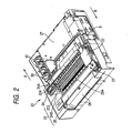
- Fig. 2 is a perspective view showing a recording mechanism 20 from backside in a multifunction device that is applied to this embodiment.
- the recording mechanism 20 is an inkjet-type, having a recording unit 21 on its rear side (showed as a near side in Fig.2 ).
- the recording unit 21 broadly includes a carriage 22 having a printing head 22c (functioning as a recording portion of the invention), a carriage guide 2 3, a carriage driving motor 203 and a timing belt 204.
- the carriage guide 23 includes a pair of guide plates 24, 25 that extend in a lateral direction of the recording mechanism 20.
- Each of the guide plates 24 and 25 is made of metal, and is disposed along with each other at a rear portion of the recording mechanism 20 and is arranged in a forward and backward direction viewed by a user.
- the guide plate 24 has a guide portion 24B at a rear end portion thereof for guiding the carriage 22 in a direction perpendicular to a transporting direction of the recording paper.
- the guide portion 24B is formed by bending a part of the guide plate 24.
- the sliding portions 24A and 25A are provided on a frond end side of the guide plate 25 and the rear end side of the guide plate 24.
- the carriage 22 is provided with a groove portion 22a that is engageable with the guide portion 24B and protrusion portions 22b protruding downward. (See Fig. 15 )
- the carriage 22 is mounted so as to be bridged between both of the guide plates 24 and 25.
- the groove portion 22a is slidably engaged with the guide portion 24B and lower surfaces of the protrusion portions 22b are brought in contact with the sliding portions 24A and 25A.
- the carriage 22 is positioned heightwise with respect to the recording paper.
- the protrusion portion 22b slides on the sliding portions 24A and 25A while being guided by the guide portion 24B, and the carriage 22 reciprocates in a direction crossing the recording paper laterally.
- a main control board (not shown) is disposed being covered by a metal shield case 27.
- a paper feeding cassette and a recording-paper transporting unit are disposed (not shown) .
- a plate 28 for making the recording paper U-turn is provided on the rear end of the recording mechanism 20.
- the recording-paper transporting unit functions to send the recording paper out sheet-by-sheet, from the front side of the recording mechanism 20 to the rear side of the recoding mechanism 20 (in a direction indicated by "R" direction in Fig.2 ).
- the sent recording paper is reversed in 180 degree from the lower side to the upper side through the plate 28 for U-turning, and is further transported from the rear side of the recording mechanism 20 to the front side of the recording mechanism 20 (in a direction indicated by "P" direction in Fig.2 ). Further, the recording paper is printed (recorded) by the printing head 22c at a printing position and afterwards ejected on the paper feeding cassette (not shown).
- Ink cartridges 30 (hereinafter, simply referred to as "cartridge") are accommodated by a holder 60.
- the holder 60 which will be later described in detail, is provided with an ink-flow passage and an air-flow passage.
- the ink discharged from the cartridge 30 is supplied to the printing head 22c ( Fig. 15 ) through the ink-flow passage and an ink transporting tube S.
- the air pressure in an ink room 31 may be reduced in accordance with the discharge of the ink.
- the air is introduced into the cartridge 30 via the air-flow passage so that the air pressure in the ink room 31 is maintained substantially the same as the atmosphere pressure.
- the cartridge 30 is box-shaped and the interior of the cartridge 30 is formed as the ink room 31 in which the ink is filled.
- a float 32 is provided in the ink room 31.
- the float 32 is inclinable around a hinge 32A so that the float 32 changes the posture thereof according to the remaining amount of the ink (the position of the liquid level of the ink). Therefore, by detecting the position of the tip end portion by a sensor (not shown) that is mounted on the holder 60, it is possible to sense the remaining amount of the ink in the cartridge 30.
- the position of the float shown in Fig. 4 corresponds to the condition in which the ink is empty. In the condition in which the ink is filled, the float 32 is brought into the standing posture.
- an ink supply port 33 communicating with the ink room 31 and an air tower 38 that is disposed at the side of the ink supply port 33.
- the ink supply port 33 is opened downward and accommodates therein an ink packing 41 having a first valve body 45 of the normally closed-type.
- the center portion of the ink packing 41 is provided with an ink outlet hole 42 that is normally closed by the first valve body 45.
- the ink outlet hole 42 is formed to allow a tip end portion of an ink receptive portion 81, which will be later described, to be inserted therein from below.
- the air tower 38 is cylindrically formed so as to penetrate the ink room 31 in the upright direction.
- the upper end of the air tower 38 is formed in height so as to face with a roof wall 31A ( Fig. 3 ) of the ink room 31.
- the position of the upper end of the air tower 38 is set higher than the liquid level of the ink in the initial filling condition of the ink in the ink room. Due to this, the ink filled in the ink room does not flow into the air tower 38 when the cartridge 30 is not in an inclined posture.
- the lower portion of the air tower 38 is provided with an air inlet port 39.
- the air inlet port 39 is formed larger in inner diameter than the other portion of the air tower 38 so that the air inlet port 39 can accommodate an air packing 51 having a second valve body 55 of the normally closed type.
- the second valve body 55 includes a rod-like body portion 56 that penetrates an air hole 52 formed in the air packing 51 in the upright direction.
- the outer peripheral portion of the second valve body 55 is provided with a seal edge 57 that seals the air inlet port 39 as well as the air hole 52 by being in close contact with an upper opening surface 52A of the air hole 52.
- the lower end portion of the body portion 56A of the second valve body 55 is in a condition of protruding from the lower surface of the cartridge 30 at the time before the cartridge 30 is mounted on the holder 60. Further, a cylindrical lip 53 is provided on the bottom surface of the air packing 51 so as to surround the lower end portion of the second valve body 55.
- the holder 60 has a parallel-piped shape. As shown in Fig. 8 , the holder 60 includes a locking clutch 69 having a guiding portion 69a and a retaining rib 69b, on a side wall located on a front side of Fig. 8 .
- the guiding portion 69a and the retaining rib 69b are used to fix the holder 60 to a casing on which the holder 60 is mounted.
- a right edge portion (a hang-over portion 64) of the bottom wall 71 protrudes toward a side direction.
- An inserting portion 691 for the casing is formed at an end portion of the hang-over portion 64.
- dividing walls 65 are provided inside the holder 60.
- the dividing walls 65 extend straightly from the side wall 61 on one side (that is, the side wall 61 located on an upper side of Fig. 7 ) toward the opposite side wall 62.
- the dividing walls 65 partition the inside of the holder 60 into four cartridge housing rooms 68.
- the first to third cartridge housing rooms 68 from the left have widths substantially equal to each other.
- the rightmost cartridge housing room 68 has a width wider somewhat larger than those of the other cartridge housing rooms 68.
- Front ends of the dividing walls 65 do not reach the side wall 62. This is because foam 100 (functioning as an ink absorbingbody) described later will be arranged in the vicinity of the side wall 62 so that the foam 100 straddles the cartridge housing rooms 68.
- elastic locking arms 67 are provided on the dividing walls 65 and the left-side wall 63, respectively. As shown in Fig. 3 , the elastic locking arms 67 extend toward the upper side of the drawing from an upper wall of the left-side wall 63 and upper walls of the dividing walls 65, respectively.
- a locking clutch 67A which can engage with a roof wall 31A of the cartridge 30, is provided at an end portion of each elastic locking arm 67. with this configuration, each elastic locking arm 67 retains the cartridge 30 mounted on the holder 60.
- Openings 71B are defined in the bottom wall 71 of the holder 60 so that each opening 71B has a shape following an outline of each locking clutch 67A.
- the openings 71B are defined to serve as relief holes, in consideration of an operation of opening molds when the locking clutches 67A are molded.
- the bottom wall 71 of each cartridge housing room 68 expands toward the upper side of the drawing (hereinafter, this portion of the bottom wall 71 is referred to as an expanding portion 75). Steps are formed between the expanding portions 75 and the other portions (hereinafter, referred to as base portions 72).
- the steps of the bottom walls 71 have height substantially equal to a sum of thickness of the foam 100 disposed on the base portions 72 and thickness of a holding plate 110 disposed on the foam 100. It is noted that the bottom walls 71 function as a base of the holder 60.
- Ink receptive portions 81 are integrally formed at positions facing the ink supply ports 33 of the cartridges 30 and on a side of the base portions 72 of the bottom walls 71.
- An outer dimension of a tip end portion of each ink receptive portion 81 is slightly larger than an inner diameter of the ink outlet hole 42.
- a guiding taper 42A is formed on a peripheral edge of each ink outlet hole 42. Therefore, when the ink receptive portions 81 are inserted into the ink packings 41 in a press fit manner, the ink receptive portions 81 move into the ink outlet holes 42.
- Circular receiving face portions 85 are provided on a side of the expanding portions 75 of the bottom walls 71, at positions facing the air towers 38, respectively.
- the circular receiving face portions 85 function as an air connecting portion.
- An air inlet hole 86 is defined at a center portion of each circular receiving face portion 85.
- An upper portion of each air inlet hole 86 is larger in an inner diameter than a lower portion thereof.
- a lower end portion of a second valve body 55 abuts against the upper portion of each air inlet hole 86. Therefore, when the cartridges 30 are mounted in the cartridge housing rooms 68, the second valve bodies 55 abut against the step portions of the air inlet holes 86, thereby pressing the second valve bodies 55 upward. As a result, the second valve bodies 55 open the air holes 52.
- a slit 56A is defined in the lower end portion of each second valve body 55.
- the air inlet holes 86 and the slits 56A continue to each other, respectively. Therefore, air can flow from an air inlet hole 86 side through the air inlet ports 39 to the inside of the ink rooms 31.
- a cylindrical lip 53 of each air packing 51 elastically contacts with the upper surface of the circular receiving face portion 85 while being bent inward, to seal between an inner portion of the air tower 38 and the circular receiving face portion 85.
- the second valve body 55 is opened slightly earlier than the first valve body 45.
- a pressure of the ink room 41 is set to be lower than air pressure. Therefore, if the first valve body 45 were opened earlier than the second valve body 55 or the first valve body 45 and the second valve body 55 were opened simultaneously, ink would be absorbed from the printing head 22c through the ink transporting tube S, resulting in destroying meniscus formed in the nozzle portion 22d of the printing head 22c. Therefore, the second valve body 55 is opened earlier than the first valve body 45 in order to prevent the meniscus from being destroyed.
- ink grooves 83 communicating with the ink receptive portions 81 and air grooves 93 communicating with the air inlet holes 86 will be described with reference to Figs. 9 , 10 and 14 .
- the ink grooves 83 are formed (recessed) on a lower face 71A of the bottom wall 71, that is, on a face opposite to the side where the cartridge 30 is mounted, for each ink receptive portion 81.
- the ink grooves 83 obliquely extend from the ink receptive portions 81, extend sideways (right side in Fig. 9 ) along a side edge (upper edge in Fig. 9 ) of the holder 60, and then obliquely extend toward a hang-over portion 64 formed on the right side portion of the holder 60.
- Portions of the ink grooves 83 other than starting end side portions are constructed such that the adjacent ink grooves 83 share a part of groove wall.
- one groove wall 84B of the ink groove 83B is connected to a groove wall 84A of the ink groove 83A in its midway portion, and then the ink groove 83B is formed between the groove wall 84B and the groove wall 84A of the ink groove 83A. Since the part of groove wall is commonly used in this manner, the width of the arrangement space of the grooves can be reduced.
- a plastic sheet having a low heat conductance (for example, GX film manufactured by Toppan Co., Ltd.) is heat-welded to the lower face of the holder 60. More specifically, on the groove edges of the ink grooves 83 and on the periphery of the holder 60, welding ribs 91 are formed. Each of the welding ribs 91 has, as shown in Fig. 10A , a triangular sectional shape, and the tip end side thereof is made narrower than the base end side thereof. The welding ribs 91 are provided on the entire groove edges. The welding rib 91 is provided on almost the whole peripheral edge of the holder 60 except for a portion where the ink grooves 83 are formed.
- the welding ribs 91 melt and the plastic sheet F comes in close contact with the periphery of the holder 60. Further, the ink grooves 83 and the air grooves 93 described later are sealed without voids so that the both grooves 83, 93 are heat sealed. Incidentally, the plastic sheet F functions as the supplemental member.
- the tip end of the welding rib 91 narrow and the base end of the welding rib 91 thick, the melt of the welding rib 91 by heating is facilitated and the welding voids are prevented from being formed. Further, since the periphery of the holder 60 is heat-welded in addition to the edges of the ink grooves 83 and the air grooves 93, even in a case where the ink is leaked when attaching or detaching the cartridge 30, the ink thus leaked does not drop through some holes that are requited for injection molding and formed on the holder 60 because the whole of the lower face 71a is covered with the plastic sheet F. Therefore, contamination of the inside of the apparatus is prevented.
- the structure in which the ink grooves 83 are covered with the plastic sheet F functions as the ink flow path, and the structure in which the air grooves are covered with the sheet functions as the air flow path.
- each of the air grooves 93 is provided with an ink pooling portion 95 that is formed in a size that surrounds the circular receiving face portion 85, and a meandering portion 97 that is formed above, as shown in Fig. 9 , the ink pooling portion 95.
- the meandering portion 97 is formed to extend near to the ink receptive portion 81 while meandering in left and right direction, and is provided with an opening 98 at a leading edge thereof, the opening 98 that communicates through the bottom wall 71 in up and down direction.
- the air groove 93 arranged at rightmost in Fig. 9 is configured to have a shape different from other air grooves 93 in order to form the air groove 93 away from the portion where the ink groove 83 is formed.
- the welding rib 91 is formed around entire circumference of each of the ink pooling portions 95 and the meandering portions 97 along the edge of the ink pooling portions 95 and the meandering portions 97. According to this configuration, when the heat pressing is performed, the plastic sheet F is closely attached along the edge of the air grooves 93, whereby the air grooves 93 are heat-sealed. Accordingly, air is introduced into the air tower 38 through the opening 98, the air groove 93, the air inlet hole 86, and the air inlet port 39.
- the meandering portion 97 is provided for allowing the air to be less flowable in the air groove 93 and for obtaining more length for the passage of the air groove 93.
- the air groove 93 has shorter passage and configured to allow the air to be more flowable therein, the air circulation in the cartridge 30 is improved and the ink in the cartridge 30 dries faster.
- the drying of the ink in the cartridge 30 is delayed by providing the meandering portion 97.
- a groove width of the meandering portion 97 is configured to be substantially equal to a groove width of the ink groove 83.
- the meandering portion 97 is configured to be more shallow than the ink groove 83 in order to prevent a vaporization of the ink by reducing a movement of the air, which is a gas that has less passage friction with respect to the liquid of the ink.
- a foam 100 is provided.
- the foam 100 is formed by a urethane member and is provided with four slits 101 formed in plate having a key-like shape and arranged to be juxtaposed with each other ( Fig. 10 ).
- the slits 101 serves as escape ports to avoid interference with the dividing wall 65 formed on the holder 60 and with the ink receptive portion 81.
- the foam 100 when attached, is configured to cover the circumference of the surface of the bottom wall 71 at the opening 98. Accordingly, when the ink flow backwards from the opening 98 to the upper surface of the bottom wall 71 (i.e. when the ink is reserved in the ink pooling portion 95 to the amount that reaches the opening 98), the foam 100 sucks the ink to avoid the inner portion of the holder 60 to be tainted.
- a supporting protrusion portion 98A is provided at a rim of each of the opening 98. The supporting protrusion portion 98A protrudes to the side where the foam 100 is provided and supports the foam 100 from below to retain the foam 100 in a curved state as shown in Fig. 14 . According to the configuration that the foam 100 is retained in a state spaced apart from the opening 98, air permeability is assured.
- the empty cartridge 30 is removed from the holder 60.
- a latching is released by pushing the end part of the elastic locking arm 67 latched with the cartridge 30 in the lock-releasing direction. From this state, bylifting the cartridge 30 upward, the ink receptive portion 81 is retreated from the ink packing 41, and the ink cartridge 30 is removed from the holder 60.
- a new cartridge filled with ink is attached. For that, a bottom face of the cartridge 30 is kept directed downwardly. Further, an ink supply port 33 and an air tower 38 of the cartridge are rendered to be opposed to an ink receptive portion 81 and a circular receiving face portion 85 of the holder 60. From this state, the cartridge 30 is pushed toward the holder 60.
- the ink run out from the cartridge 30, is sent to the ink transporting tube S through the ink supply port 33, the ink path and the ink connecting portion 92.
- a drawing direction of the ink transporting tube S can be arbitrarily determined, since the ink path is configured to be intervened between the ink receptive portion 81 and the ink transporting tube S.
- the ink transporting tube S can be disposed from any position other than a rear face 71A of the bottom wall 71, and space saving becomes possible.
- a structure is simple, since the ink path is formed only by pasting (heat welding) a plastic film sheet F on the rear face 71A of the holder bottom wall 71.
- the ink groove 83 and the air groove 93 are formed on the rear face 71A of the bottom wall 71. Then, the ink groove 83 and the air groove 93 can be sealed by one plastic sheet F in a lump. Accordingly, a production efficiency is better than that when each of the ink groove 93 and the air groove 93 is sealed by a separate sheet.
Landscapes
- Ink Jet (AREA)
- Dot-Matrix Printers And Others (AREA)
- Particle Formation And Scattering Control In Inkjet Printers (AREA)
Claims (19)
- Tintenlieferstruktur zum Liefern von Tinte, die aus einer Tintenpatrone (30) heraus fließt, die eine Tintenlieferöffnung (33) enthält, über eine Tintentransportröhre (S) zu einem Aufzeichnungsabschnitt (22), mit:einem Tintenpatronenhalter (60) mit einer Basis (71) mit einem Patronenverbindungsabschnitt (81), über den die Tinte aus einer Tintenpatrone (30) heraus fließt, wenn der Patronenverbindungsabschnitt (81) mit der Tintenlieferöffnung (33) der Tintenpatrone (30) durch Laden der Tintenpatrone (30) in den Tintenpatronenhalter (60) verbunden ist;einem Tintenflusspfad (83), der mit der Tintentransportröhre (81) verbunden ist;einem Röhrenverbindungsabschnitt (92), der mit der Tintentransportröhre (S) verbunden ist;dadurch gekennzeichnet,dass die Tintenpatronenhalterbasis (71) eine untere Fläche (71A) aufweist, die eine Fläche gegenüber der Seite ist, an der die Patrone (30) angebracht ist, und ein zusätzliches Teil (F) auf die untere Fläche (71A) der Tintenpatronenhalterbasis (71) gepaßt ist,wobei der Tintenflusspfad (83) auf der zugehörigen Fläche zwischen der unteren Fläche (71A) der Tintenpatronenhalterbasis (71) und dem zusätzlichen Teil (F) gebildet ist.
- Tintenlieferstruktur nach Anspruch 1,
bei der der Patronenverbindungsabschnitt (81) in einer Röhrenform zum Einführen in die Tintenlieferöffnung (33) gebildet ist, wobei der Patronenverbindungsabschnitt (81) einstückig mit der Tintenpatronenhalterbasis (71) gebildet ist. - Tintenlieferstruktur nach Anspruch 1 oder 2,
bei der der Röhrenverbindungsabschnitt (92) in einer Röhrenform zur Außenpassung mit der Tintentransportröhre (S) gebildet ist und
bei der der Röhrenverbindungsabschnitt (92) einstückig mit der Basis (71) des Tintenpatronenhalters (60) gebildet ist. - Tintenlieferstruktur nach Anspruch 1 oder 2,
bei der Röhrenverbindungsabschnitt (92) außen mit der Tintentransportröhre (S) gepaßt ist,
bei der der Röhrenverbindungsabschnitt (92) in eine Röhrenform zum Vorstehen entlang einer Laderichtung einer Tintenpatrone (30) gebildet ist und
bei der der Röhrenverbindungsabschnitt (92) einstückig mit der Basis (71) des Tintenpatronenhalters (60) gebildet ist. - Tintenlieferstruktur nach einem der vorhergehenden Ansprüche,
bei der eine Tintenrille (83) den Tintenflusspfad (83) in der unteren Fläche (71A) des Tintenpatronenhalters (71) bildet und
bei der die Tintenrille (83) durch das zusätzliche Teil (F) bedeckt ist. - Tintenlieferstruktur nach Anspruch 5,
bei der das zusätzliche Teil (F) eine Kunststoffplatte (F) ist, die an der unteren Fläche (71A) der Tintenpatronenhalterbasis (71) angebracht ist, und
bei der die Kunststoffplatte (F) die Tintenrille (83) abdeckt. - Tintenlieferstruktur nach Anspruch 6,
bei der eine Schweißrippe (91), die sich entlang der Tintenrille (83) erstreckt, an einer Rillenkante der Tintenrille (83) vorgesehen ist, und
bei der die Kunststoffplatte (F) an der Schweißrippe (91) wärmegeschweißt ist. - Tintenlieferstruktur nach Anspruch 7,
bei der ein Querschnitt der Schweißrippe (91) vor dem Schweißen allmählich von einem Basisende der Schweißrippe (91) zu einem spitzen Ende der Schweißrippe angeschrägt ist. - Tintenlieferstruktur nach einem der vorhergehenden Ansprüche,
bei der die Basis (71) des Tintenpatronenhalters (60) mit einer Seitenwand (61, 62, 63) versehen ist, die eine Seite der Tintenpatrone (30) umgibt, wenn die Basis mit der Tintenpatrone (30) beladen ist. - Tintenlieferstruktur nach einem der vorhergehenden Ansprüche,
bei der die Tintenpatrone (30) elastisch durch einen elastischen Verriegelungsarm (67) zurückgehalten wird, der mit der Basis (71) des Tintenpatronenhalters (60) versehen ist, wenn die Basis (71) mit der Tintenpatrone (30) beladen ist. - Tintenlieferstruktur nach einem der vorhergehenden Ansprüche,
bei der ein Lufteinlassloch (39) zum Fließenlassen von Luft in die Tintenpatrone (30) gemäß einem Tintenfluss in der Tintenpatrone (30) vorgesehen ist,
bei der das Tinteneinlassloch (39) so gebildet ist, dass es durch einen Ventilkörper (55) in einem geschlossenen Zustand ist,
bei der ein Luftverbindungsabschnitt (86), der mit dem Lufteinlassloch (39) durch Öffnen des Ventilkörpers (55) verbunden ist, auf der Basis (71) des Tintenpatronenhalters (60) vorgesehen ist,
bei der ein Luftflusspfad (93) zwischen der zugehörigen unteren Fläche (71A) der Basis (71) des Tintenpatronenhalters (60) und dem zusätzlichen Teil (F) gebildet ist,
bei der ein Ende des Luftflusspfads (93) mit dem Luftverbindungsabschnitt (86) verbunden ist und
bei der eine Öffnung (98) sich zu der Atmosphäre an dem anderen Ende des Luftflusspfads (93) öffnet. - Tintenlieferstruktur nach Anspruch 11,
bei der der Luftflusspfad (93) als eine Rille (93) in der unteren Fläche (71A) der Basis (71) des Tintenpatronenhalters (60) aufgebaut ist und
bei der die Luftrille (93) durch das zusätzliche Teil (F) bedeckt ist. - Tintenlieferstruktur nach Anspruch 11 oder 12,
bei der der Luftflusspfad (93) in einer Mäanderform gebogen ist. - Tintenlieferstruktur nach Anspruch 11, 12 oder 13,
bei der ein Tintensammelabschnitt (95) die Tinte sammelt, die rückwärts zu der Luftflusspfadseite über das Tinteneinlassloch (39) in der Tintenpatrone (30) fließt. - Tintenlieferstruktur nach einem der Ansprüche 11 bis 13, bei der ein plattenförmiges poröses tintenabsorbierendes Teil (100) entlang einer Seitenfläche der Tintenpatronenhalterbasis (71) gehalten wird und
bei der sich die Öffnung (98) des Luftflusspfads (93) zum Kontaktieren mit dem tintenabsorbierenden Teil (100) öffnet. - Tintenlieferstruktur nach einem der Ansprüche 11 bis 15, bei der ein tragendes Vorsprungsteil (98A), das zum Tragen des tintenabsorbierenden Teils (100) in einem schwebenden Zustand von der Öffnung (98) betätigbar ist, an einem Randkantenabschnitt der Öffnung in der Patronenhalterbasis (71) vorgesehen ist, während das tragende Vorsprungsteil (98A) zu einer Seite des tintenabsorbierenden Teils vorsteht.
- Tintenlieferstruktur nach Anspruch 15,
bei der das tintenabsorbierende Teil (100) an einer Ladeseite der Tintenpatrone in der Tintenpatronenhalterbasis (71) vorgesehen ist und
bei der eine Halterplatte (110) zwischen dem tintenabsorbierenden Teil (100) und der Tintenpatrone (30) vorgesehen ist. - Multifunktionsvorrichtung (10) mit:mindestens einem Scanner;mindestens einem Telefon;einem Drucker mit:einer Tintenlieferstruktur nach einem der vorhergehenden Ansprüche.
- Drucker (10) mit:einer Tintenlieferstruktur nach einem der Ansprüche 1 bis 17.
Applications Claiming Priority (2)
| Application Number | Priority Date | Filing Date | Title |
|---|---|---|---|
| JP2004064325A JP4206938B2 (ja) | 2004-03-08 | 2004-03-08 | インクの供給構造、及びインクの供給構造の製造方法 |
| JP2004064325 | 2004-03-08 |
Publications (2)
| Publication Number | Publication Date |
|---|---|
| EP1574342A1 EP1574342A1 (de) | 2005-09-14 |
| EP1574342B1 true EP1574342B1 (de) | 2011-04-27 |
Family
ID=34824530
Family Applications (1)
| Application Number | Title | Priority Date | Filing Date |
|---|---|---|---|
| EP05251385A Not-in-force EP1574342B1 (de) | 2004-03-08 | 2005-03-08 | Mehrfach-Funktions-Gerät, Drucker und Farbstoffzufuhrvorrichtung dafür |
Country Status (6)
| Country | Link |
|---|---|
| US (1) | US7393087B2 (de) |
| EP (1) | EP1574342B1 (de) |
| JP (1) | JP4206938B2 (de) |
| CN (1) | CN100528575C (de) |
| AT (1) | ATE507077T1 (de) |
| DE (1) | DE602005027631D1 (de) |
Families Citing this family (9)
| Publication number | Priority date | Publication date | Assignee | Title |
|---|---|---|---|---|
| JP4518038B2 (ja) * | 2006-03-31 | 2010-08-04 | ブラザー工業株式会社 | インクリフィルユニット |
| JP4569507B2 (ja) | 2006-03-31 | 2010-10-27 | ブラザー工業株式会社 | インクジェット記録装置 |
| JP4466598B2 (ja) | 2006-03-31 | 2010-05-26 | ブラザー工業株式会社 | インクリフィルユニット |
| JP4929917B2 (ja) * | 2006-08-17 | 2012-05-09 | セイコーエプソン株式会社 | カートリッジホルダの組み付け構造及び記録装置 |
| JP4904985B2 (ja) * | 2006-08-17 | 2012-03-28 | セイコーエプソン株式会社 | カートリッジホルダの組み付け構造及び記録装置 |
| JP6036019B2 (ja) * | 2012-08-31 | 2016-11-30 | セイコーエプソン株式会社 | 液体噴射装置 |
| JP6287144B2 (ja) * | 2013-12-06 | 2018-03-07 | ブラザー工業株式会社 | インクジェット記録装置、複合機、及びインクカートリッジ収容体 |
| JP6794783B2 (ja) * | 2016-11-04 | 2020-12-02 | セイコーエプソン株式会社 | 液体噴射装置 |
| JP7528536B2 (ja) * | 2020-05-27 | 2024-08-06 | セイコーエプソン株式会社 | 液体噴射装置 |
Family Cites Families (11)
| Publication number | Priority date | Publication date | Assignee | Title |
|---|---|---|---|---|
| JP2804684B2 (ja) | 1992-08-25 | 1998-09-30 | アルプス電気株式会社 | インクカートリッジ |
| US5980032A (en) * | 1994-10-31 | 1999-11-09 | Hewlett-Packard Company | Compliant ink interconnect between print cartridge and carriage |
| JP2001130020A (ja) | 1999-11-02 | 2001-05-15 | Seiko Epson Corp | インクジェット式プリンタ |
| ATE461043T1 (de) * | 1999-11-05 | 2010-04-15 | Seiko Epson Corp | Aufzeichnungsgerät des tintenstrahltyps und verfahren zur tintenversorgung für den untertank mittels desselben gertes und verfahren zur kontrolle der dem untertank zugeführten tintenmenge mittels desselben gerätes |
| ATE269788T1 (de) * | 1999-11-05 | 2004-07-15 | Seiko Epson Corp | Tintenstrahlaufzeichnungsvorrichtung |
| EP1120258B1 (de) * | 2000-01-21 | 2006-05-17 | Seiko Epson Corporation | Tintenpatrone und Tintenstrahldruckvorrichtung mit einer derartigen Tintenpatrone |
| JP2002019135A (ja) | 2000-07-04 | 2002-01-23 | Seiko Epson Corp | 記録装置用インクカートリッジおよびインクジェット式記録装置 |
| CN101386230B (zh) * | 2000-01-21 | 2011-04-13 | 精工爱普生株式会社 | 记录装置用墨盒及喷墨式记录装置 |
| EP1386478B1 (de) * | 2002-03-28 | 2006-11-08 | Brother Kogyo Kabushiki Kaisha | Druckeinrichtung |
| JP4241177B2 (ja) * | 2003-05-09 | 2009-03-18 | セイコーエプソン株式会社 | 液体噴射装置 |
| US7384136B2 (en) * | 2003-11-25 | 2008-06-10 | Brother Kogyo Kabushiki Kaisha | Ink cartridge |
-
2004
- 2004-03-08 JP JP2004064325A patent/JP4206938B2/ja not_active Expired - Fee Related
-
2005
- 2005-03-08 EP EP05251385A patent/EP1574342B1/de not_active Not-in-force
- 2005-03-08 DE DE602005027631T patent/DE602005027631D1/de not_active Expired - Lifetime
- 2005-03-08 US US11/073,946 patent/US7393087B2/en not_active Expired - Fee Related
- 2005-03-08 AT AT05251385T patent/ATE507077T1/de not_active IP Right Cessation
- 2005-03-08 CN CNB2005100544938A patent/CN100528575C/zh not_active Expired - Fee Related
Also Published As
| Publication number | Publication date |
|---|---|
| US7393087B2 (en) | 2008-07-01 |
| JP4206938B2 (ja) | 2009-01-14 |
| CN1680103A (zh) | 2005-10-12 |
| US20050195253A1 (en) | 2005-09-08 |
| JP2005246922A (ja) | 2005-09-15 |
| DE602005027631D1 (de) | 2011-06-09 |
| ATE507077T1 (de) | 2011-05-15 |
| EP1574342A1 (de) | 2005-09-14 |
| CN100528575C (zh) | 2009-08-19 |
Similar Documents
| Publication | Publication Date | Title |
|---|---|---|
| CN101130309B (zh) | 墨盒 | |
| US7237882B2 (en) | Ink cartridge having retaining structure and recording apparatus for receiving the ink cartridge | |
| CN101130308B (zh) | 墨盒和供墨系统 | |
| US9233546B2 (en) | Liquid supply unit | |
| JP5094273B2 (ja) | インクタンク | |
| US7926926B2 (en) | Liquid container | |
| WO2007146029A2 (en) | Facade for an ink tank | |
| TW200520978A (en) | Liquid container | |
| US20040076447A1 (en) | Tank holder, liquid tank and tank attaching and detaching method | |
| JP2016010888A (ja) | 液体収納容器及び液体吐出装置 | |
| US20160082736A1 (en) | Waste liquid container, attachment, waste liquid collection unit, and liquid ejecting apparatus | |
| NZ280044A (en) | Multi-chambered ink cartridge for ink jet printer | |
| EP1574342B1 (de) | Mehrfach-Funktions-Gerät, Drucker und Farbstoffzufuhrvorrichtung dafür | |
| US20050179752A1 (en) | Liquid container | |
| CN101219605B (zh) | 液体容器 | |
| CN100382972C (zh) | 具有气体吸收装置的液体容器 | |
| EP1510347B1 (de) | Tintenbehälter | |
| JP5304110B2 (ja) | 液体カートリッジユニット | |
| JP3564895B2 (ja) | インクタンクおよびインクジェット記録装置 | |
| JP2001113722A (ja) | インクジェット記録装置 | |
| JP2006116786A (ja) | 液体収納容器および該容器用ホルダ | |
| TWI649215B (zh) | 液體收容體、液體消耗裝置及電連接體 | |
| JP4114086B2 (ja) | インクカートリッジ | |
| JP4748189B2 (ja) | 空気流入構造、及び空気流入構造の製造方法 | |
| JP4296443B2 (ja) | インクカートリッジのインク注入方法 |
Legal Events
| Date | Code | Title | Description |
|---|---|---|---|
| PUAI | Public reference made under article 153(3) epc to a published international application that has entered the european phase |
Free format text: ORIGINAL CODE: 0009012 |
|
| AK | Designated contracting states |
Kind code of ref document: A1 Designated state(s): AT BE BG CH CY CZ DE DK EE ES FI FR GB GR HU IE IS IT LI LT LU MC NL PL PT RO SE SI SK TR |
|
| AX | Request for extension of the european patent |
Extension state: AL BA HR LV MK YU |
|
| 17P | Request for examination filed |
Effective date: 20050909 |
|
| AKX | Designation fees paid |
Designated state(s): AT BE BG CH CY CZ DE DK EE ES FI FR GB GR HU IE IS IT LI LT LU MC NL PL PT RO SE SI SK TR |
|
| 17Q | First examination report despatched |
Effective date: 20060918 |
|
| GRAP | Despatch of communication of intention to grant a patent |
Free format text: ORIGINAL CODE: EPIDOSNIGR1 |
|
| GRAS | Grant fee paid |
Free format text: ORIGINAL CODE: EPIDOSNIGR3 |
|
| GRAA | (expected) grant |
Free format text: ORIGINAL CODE: 0009210 |
|
| AK | Designated contracting states |
Kind code of ref document: B1 Designated state(s): AT BE BG CH CY CZ DE DK EE ES FI FR GB GR HU IE IS IT LI LT LU MC NL PL PT RO SE SI SK TR |
|
| REG | Reference to a national code |
Ref country code: GB Ref legal event code: FG4D |
|
| REG | Reference to a national code |
Ref country code: CH Ref legal event code: EP |
|
| REG | Reference to a national code |
Ref country code: IE Ref legal event code: FG4D |
|
| REF | Corresponds to: |
Ref document number: 602005027631 Country of ref document: DE Date of ref document: 20110609 Kind code of ref document: P |
|
| REG | Reference to a national code |
Ref country code: DE Ref legal event code: R096 Ref document number: 602005027631 Country of ref document: DE Effective date: 20110609 |
|
| REG | Reference to a national code |
Ref country code: NL Ref legal event code: VDEP Effective date: 20110427 |
|
| LTIE | Lt: invalidation of european patent or patent extension |
Effective date: 20110427 |
|
| PG25 | Lapsed in a contracting state [announced via postgrant information from national office to epo] |
Ref country code: SE Free format text: LAPSE BECAUSE OF FAILURE TO SUBMIT A TRANSLATION OF THE DESCRIPTION OR TO PAY THE FEE WITHIN THE PRESCRIBED TIME-LIMIT Effective date: 20110427 Ref country code: LT Free format text: LAPSE BECAUSE OF FAILURE TO SUBMIT A TRANSLATION OF THE DESCRIPTION OR TO PAY THE FEE WITHIN THE PRESCRIBED TIME-LIMIT Effective date: 20110427 Ref country code: PT Free format text: LAPSE BECAUSE OF FAILURE TO SUBMIT A TRANSLATION OF THE DESCRIPTION OR TO PAY THE FEE WITHIN THE PRESCRIBED TIME-LIMIT Effective date: 20110829 |
|
| PG25 | Lapsed in a contracting state [announced via postgrant information from national office to epo] |
Ref country code: GR Free format text: LAPSE BECAUSE OF FAILURE TO SUBMIT A TRANSLATION OF THE DESCRIPTION OR TO PAY THE FEE WITHIN THE PRESCRIBED TIME-LIMIT Effective date: 20110728 Ref country code: BE Free format text: LAPSE BECAUSE OF FAILURE TO SUBMIT A TRANSLATION OF THE DESCRIPTION OR TO PAY THE FEE WITHIN THE PRESCRIBED TIME-LIMIT Effective date: 20110427 Ref country code: AT Free format text: LAPSE BECAUSE OF FAILURE TO SUBMIT A TRANSLATION OF THE DESCRIPTION OR TO PAY THE FEE WITHIN THE PRESCRIBED TIME-LIMIT Effective date: 20110427 Ref country code: IS Free format text: LAPSE BECAUSE OF FAILURE TO SUBMIT A TRANSLATION OF THE DESCRIPTION OR TO PAY THE FEE WITHIN THE PRESCRIBED TIME-LIMIT Effective date: 20110827 Ref country code: ES Free format text: LAPSE BECAUSE OF FAILURE TO SUBMIT A TRANSLATION OF THE DESCRIPTION OR TO PAY THE FEE WITHIN THE PRESCRIBED TIME-LIMIT Effective date: 20110807 Ref country code: SI Free format text: LAPSE BECAUSE OF FAILURE TO SUBMIT A TRANSLATION OF THE DESCRIPTION OR TO PAY THE FEE WITHIN THE PRESCRIBED TIME-LIMIT Effective date: 20110427 Ref country code: CY Free format text: LAPSE BECAUSE OF FAILURE TO SUBMIT A TRANSLATION OF THE DESCRIPTION OR TO PAY THE FEE WITHIN THE PRESCRIBED TIME-LIMIT Effective date: 20110427 Ref country code: FI Free format text: LAPSE BECAUSE OF FAILURE TO SUBMIT A TRANSLATION OF THE DESCRIPTION OR TO PAY THE FEE WITHIN THE PRESCRIBED TIME-LIMIT Effective date: 20110427 |
|
| PG25 | Lapsed in a contracting state [announced via postgrant information from national office to epo] |
Ref country code: NL Free format text: LAPSE BECAUSE OF FAILURE TO SUBMIT A TRANSLATION OF THE DESCRIPTION OR TO PAY THE FEE WITHIN THE PRESCRIBED TIME-LIMIT Effective date: 20110427 |
|
| PG25 | Lapsed in a contracting state [announced via postgrant information from national office to epo] |
Ref country code: CZ Free format text: LAPSE BECAUSE OF FAILURE TO SUBMIT A TRANSLATION OF THE DESCRIPTION OR TO PAY THE FEE WITHIN THE PRESCRIBED TIME-LIMIT Effective date: 20110427 Ref country code: EE Free format text: LAPSE BECAUSE OF FAILURE TO SUBMIT A TRANSLATION OF THE DESCRIPTION OR TO PAY THE FEE WITHIN THE PRESCRIBED TIME-LIMIT Effective date: 20110427 |
|
| PG25 | Lapsed in a contracting state [announced via postgrant information from national office to epo] |
Ref country code: SK Free format text: LAPSE BECAUSE OF FAILURE TO SUBMIT A TRANSLATION OF THE DESCRIPTION OR TO PAY THE FEE WITHIN THE PRESCRIBED TIME-LIMIT Effective date: 20110427 Ref country code: DK Free format text: LAPSE BECAUSE OF FAILURE TO SUBMIT A TRANSLATION OF THE DESCRIPTION OR TO PAY THE FEE WITHIN THE PRESCRIBED TIME-LIMIT Effective date: 20110427 Ref country code: RO Free format text: LAPSE BECAUSE OF FAILURE TO SUBMIT A TRANSLATION OF THE DESCRIPTION OR TO PAY THE FEE WITHIN THE PRESCRIBED TIME-LIMIT Effective date: 20110427 Ref country code: PL Free format text: LAPSE BECAUSE OF FAILURE TO SUBMIT A TRANSLATION OF THE DESCRIPTION OR TO PAY THE FEE WITHIN THE PRESCRIBED TIME-LIMIT Effective date: 20110427 |
|
| PLBE | No opposition filed within time limit |
Free format text: ORIGINAL CODE: 0009261 |
|
| STAA | Information on the status of an ep patent application or granted ep patent |
Free format text: STATUS: NO OPPOSITION FILED WITHIN TIME LIMIT |
|
| 26N | No opposition filed |
Effective date: 20120130 |
|
| REG | Reference to a national code |
Ref country code: DE Ref legal event code: R097 Ref document number: 602005027631 Country of ref document: DE Effective date: 20120130 |
|
| PG25 | Lapsed in a contracting state [announced via postgrant information from national office to epo] |
Ref country code: IT Free format text: LAPSE BECAUSE OF FAILURE TO SUBMIT A TRANSLATION OF THE DESCRIPTION OR TO PAY THE FEE WITHIN THE PRESCRIBED TIME-LIMIT Effective date: 20110427 |
|
| PG25 | Lapsed in a contracting state [announced via postgrant information from national office to epo] |
Ref country code: MC Free format text: LAPSE BECAUSE OF NON-PAYMENT OF DUE FEES Effective date: 20120331 |
|
| REG | Reference to a national code |
Ref country code: CH Ref legal event code: PL |
|
| REG | Reference to a national code |
Ref country code: IE Ref legal event code: MM4A |
|
| PG25 | Lapsed in a contracting state [announced via postgrant information from national office to epo] |
Ref country code: IE Free format text: LAPSE BECAUSE OF NON-PAYMENT OF DUE FEES Effective date: 20120308 Ref country code: CH Free format text: LAPSE BECAUSE OF NON-PAYMENT OF DUE FEES Effective date: 20120331 Ref country code: LI Free format text: LAPSE BECAUSE OF NON-PAYMENT OF DUE FEES Effective date: 20120331 |
|
| PG25 | Lapsed in a contracting state [announced via postgrant information from national office to epo] |
Ref country code: BG Free format text: LAPSE BECAUSE OF FAILURE TO SUBMIT A TRANSLATION OF THE DESCRIPTION OR TO PAY THE FEE WITHIN THE PRESCRIBED TIME-LIMIT Effective date: 20110727 |
|
| PG25 | Lapsed in a contracting state [announced via postgrant information from national office to epo] |
Ref country code: TR Free format text: LAPSE BECAUSE OF FAILURE TO SUBMIT A TRANSLATION OF THE DESCRIPTION OR TO PAY THE FEE WITHIN THE PRESCRIBED TIME-LIMIT Effective date: 20110427 |
|
| PG25 | Lapsed in a contracting state [announced via postgrant information from national office to epo] |
Ref country code: LU Free format text: LAPSE BECAUSE OF NON-PAYMENT OF DUE FEES Effective date: 20120308 |
|
| PG25 | Lapsed in a contracting state [announced via postgrant information from national office to epo] |
Ref country code: HU Free format text: LAPSE BECAUSE OF FAILURE TO SUBMIT A TRANSLATION OF THE DESCRIPTION OR TO PAY THE FEE WITHIN THE PRESCRIBED TIME-LIMIT Effective date: 20050308 |
|
| REG | Reference to a national code |
Ref country code: FR Ref legal event code: PLFP Year of fee payment: 12 |
|
| REG | Reference to a national code |
Ref country code: FR Ref legal event code: PLFP Year of fee payment: 13 |
|
| REG | Reference to a national code |
Ref country code: FR Ref legal event code: PLFP Year of fee payment: 14 |
|
| PGFP | Annual fee paid to national office [announced via postgrant information from national office to epo] |
Ref country code: GB Payment date: 20180307 Year of fee payment: 14 |
|
| PGFP | Annual fee paid to national office [announced via postgrant information from national office to epo] |
Ref country code: FR Payment date: 20180223 Year of fee payment: 14 |
|
| PGFP | Annual fee paid to national office [announced via postgrant information from national office to epo] |
Ref country code: DE Payment date: 20190226 Year of fee payment: 15 |
|
| GBPC | Gb: european patent ceased through non-payment of renewal fee |
Effective date: 20190308 |
|
| PG25 | Lapsed in a contracting state [announced via postgrant information from national office to epo] |
Ref country code: GB Free format text: LAPSE BECAUSE OF NON-PAYMENT OF DUE FEES Effective date: 20190308 |
|
| PG25 | Lapsed in a contracting state [announced via postgrant information from national office to epo] |
Ref country code: FR Free format text: LAPSE BECAUSE OF NON-PAYMENT OF DUE FEES Effective date: 20190331 |
|
| REG | Reference to a national code |
Ref country code: DE Ref legal event code: R119 Ref document number: 602005027631 Country of ref document: DE |
|
| PG25 | Lapsed in a contracting state [announced via postgrant information from national office to epo] |
Ref country code: DE Free format text: LAPSE BECAUSE OF NON-PAYMENT OF DUE FEES Effective date: 20201001 |