EP1571831B1 - Av system - Google Patents
Av system Download PDFInfo
- Publication number
- EP1571831B1 EP1571831B1 EP03780691A EP03780691A EP1571831B1 EP 1571831 B1 EP1571831 B1 EP 1571831B1 EP 03780691 A EP03780691 A EP 03780691A EP 03780691 A EP03780691 A EP 03780691A EP 1571831 B1 EP1571831 B1 EP 1571831B1
- Authority
- EP
- European Patent Office
- Prior art keywords
- remote control
- display unit
- control code
- switch
- remote controller
- Prior art date
- Legal status (The legal status is an assumption and is not a legal conclusion. Google has not performed a legal analysis and makes no representation as to the accuracy of the status listed.)
- Expired - Lifetime
Links
- 238000000034 method Methods 0.000 description 58
- 230000005540 biological transmission Effects 0.000 description 43
- 238000010586 diagram Methods 0.000 description 41
- 238000010276 construction Methods 0.000 description 17
- 239000000284 extract Substances 0.000 description 15
- 230000006872 improvement Effects 0.000 description 8
- 230000006870 function Effects 0.000 description 6
- 239000000470 constituent Substances 0.000 description 5
- GJWAPAVRQYYSTK-UHFFFAOYSA-N [(dimethyl-$l^{3}-silanyl)amino]-dimethylsilicon Chemical compound C[Si](C)N[Si](C)C GJWAPAVRQYYSTK-UHFFFAOYSA-N 0.000 description 2
- 230000008859 change Effects 0.000 description 2
- 239000004973 liquid crystal related substance Substances 0.000 description 2
- 239000013307 optical fiber Substances 0.000 description 2
- 230000005236 sound signal Effects 0.000 description 2
- 230000002123 temporal effect Effects 0.000 description 2
- 230000004044 response Effects 0.000 description 1
- 238000007493 shaping process Methods 0.000 description 1
- 230000000007 visual effect Effects 0.000 description 1
Images


Classifications
-
- H—ELECTRICITY
- H04—ELECTRIC COMMUNICATION TECHNIQUE
- H04B—TRANSMISSION
- H04B1/00—Details of transmission systems, not covered by a single one of groups H04B3/00 - H04B13/00; Details of transmission systems not characterised by the medium used for transmission
- H04B1/06—Receivers
- H04B1/16—Circuits
- H04B1/20—Circuits for coupling gramophone pick-up, recorder output, or microphone to receiver
- H04B1/202—Circuits for coupling gramophone pick-up, recorder output, or microphone to receiver by remote control
-
- H—ELECTRICITY
- H04—ELECTRIC COMMUNICATION TECHNIQUE
- H04N—PICTORIAL COMMUNICATION, e.g. TELEVISION
- H04N21/00—Selective content distribution, e.g. interactive television or video on demand [VOD]
- H04N21/40—Client devices specifically adapted for the reception of or interaction with content, e.g. set-top-box [STB]; Operations thereof
- H04N21/41—Structure of client; Structure of client peripherals
- H04N21/4104—Peripherals receiving signals from specially adapted client devices
- H04N21/4122—Peripherals receiving signals from specially adapted client devices additional display device, e.g. video projector
-
- H—ELECTRICITY
- H04—ELECTRIC COMMUNICATION TECHNIQUE
- H04N—PICTORIAL COMMUNICATION, e.g. TELEVISION
- H04N21/00—Selective content distribution, e.g. interactive television or video on demand [VOD]
- H04N21/40—Client devices specifically adapted for the reception of or interaction with content, e.g. set-top-box [STB]; Operations thereof
- H04N21/41—Structure of client; Structure of client peripherals
- H04N21/422—Input-only peripherals, i.e. input devices connected to specially adapted client devices, e.g. global positioning system [GPS]
- H04N21/42204—User interfaces specially adapted for controlling a client device through a remote control device; Remote control devices therefor
-
- H—ELECTRICITY
- H04—ELECTRIC COMMUNICATION TECHNIQUE
- H04N—PICTORIAL COMMUNICATION, e.g. TELEVISION
- H04N21/00—Selective content distribution, e.g. interactive television or video on demand [VOD]
- H04N21/40—Client devices specifically adapted for the reception of or interaction with content, e.g. set-top-box [STB]; Operations thereof
- H04N21/41—Structure of client; Structure of client peripherals
- H04N21/426—Internal components of the client ; Characteristics thereof
- H04N21/42684—Client identification by a unique number or address, e.g. serial number, MAC address, socket ID
-
- H—ELECTRICITY
- H04—ELECTRIC COMMUNICATION TECHNIQUE
- H04N—PICTORIAL COMMUNICATION, e.g. TELEVISION
- H04N5/00—Details of television systems
- H04N5/44—Receiver circuitry for the reception of television signals according to analogue transmission standards
-
- H—ELECTRICITY
- H04—ELECTRIC COMMUNICATION TECHNIQUE
- H04N—PICTORIAL COMMUNICATION, e.g. TELEVISION
- H04N5/00—Details of television systems
- H04N5/76—Television signal recording
- H04N5/765—Interface circuits between an apparatus for recording and another apparatus
-
- H—ELECTRICITY
- H04—ELECTRIC COMMUNICATION TECHNIQUE
- H04N—PICTORIAL COMMUNICATION, e.g. TELEVISION
- H04N21/00—Selective content distribution, e.g. interactive television or video on demand [VOD]
- H04N21/40—Client devices specifically adapted for the reception of or interaction with content, e.g. set-top-box [STB]; Operations thereof
- H04N21/47—End-user applications
-
- H—ELECTRICITY
- H04—ELECTRIC COMMUNICATION TECHNIQUE
- H04N—PICTORIAL COMMUNICATION, e.g. TELEVISION
- H04N5/00—Details of television systems
- H04N5/76—Television signal recording
- H04N5/84—Television signal recording using optical recording
- H04N5/85—Television signal recording using optical recording on discs or drums
Definitions
- the present invention relates to an AV system according to the preamble of claim 1.
- EP-A-0 849 884 and EP-A-0 612 517 disclose AV systems according to the preamble of claim 1.
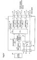
- Figure 37 shows the construction of a conventional AV switcher according to JP-A-5-83646 .
- reference numeral 1 denotes an AV switcher
- numerals 2 denotes a key operation unit
- numeral 3 denotes a light-receptive unit for receiving a remote control signal
- numeral 4 denotes a waveform shaping circuit
- numeral 5 denotes an EEPROM for holding the remote control signal
- numeral 6 denotes a CPU
- numerals 7 ⁇ 10 denote N pieces of light-emitting units for converting the remote control signals outputted from the CPU 6 into infrared remote control signals of predetermined levels, respectively
- numerals 11 ⁇ 14 denote output terminals for optical fiber cables which are provided correspondingly to the respective light-emitting units.
- Reference numerals 15 ⁇ 18 denote optical fiber cables for transmitting the infrared rays to light-receptive units of the respective devices
- numerals 19 ⁇ 21 denote signal (video/audio) input terminals
- numeral 22 denotes a switching circuit for performing switching to output a specified signal according to a switching signal 23 from the CPU
- numeral 24 denotes an output terminal for the signal selected by the switching circuit 22
- numeral 25 denotes an output signal
- numeral 26 denotes a remote controller corresponding to one of the AV devices constituting this system.
- the switching circuit 22 is placed at a position A by manual operation to connect a signal from the VTR to the output terminal 24. Further, the remote controller must be operated aiming at the AV switcher 1.
- the remote controller included in each of the AV devices must be operated with aiming at the AV switcher to manually select the corresponding AV device.
- the user is apt to operate the remote controller of the AV device connected to the display with aiming the remote controller at the display, and when the AV device and the display are placed apart from each other, remote control does not effectively work if the user operates the remote controller aiming at the display.
- the present invention is made to solve the above-described problems and has for its object to provide an AV system which, comprising a display unit and a plurality of video devices connected to the display unit, enables remote control operation of each video device with aiming a remote controller at the display.
- a video device connected to a display can be automatically recognized.
- AV system of the present invention in an environment where a plurality of AV devices such as STBs and DVD players whose makers are different from each other are connected to a display or an AV switch, a new function of operating a remote controller associated with one of the AV devices with aiming the remote controller at the display, thereby automatically selecting a device corresponding to the remote controller and automatically displaying data from the video device corresponding to the remote controller, on the display screen, can be realized. Therefore, it becomes unnecessary for a user to manually operate the display and AV switch to select a device whose data are displayed on the screen.
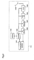
- Figure 1 is a diagram illustrating the construction of the AV system according to the first embodiment.
- reference numeral 100 denotes a display unit for displaying inputted video, and outputting audio.
- Reference numeral 101 denotes a remote controller associated with one of connected-devices described later.
- Reference numeral 102 denotes a display section for displaying video and outputting audio, and for example, the display section 102 comprises a CRT, or a liquid crystal panel, or a plasma display, and a speaker.
- Reference numeral 103 denotes a remote control receiver for receiving a signal from the remote controller 101.
- Reference numeral 104 denotes a controller of the display, for controlling the whole display unit, and, for example, it is a CPU.
- Reference numeral 105 denotes a selector for selecting video data and audio data from the plural devices connected to the display.
- Reference numeral 106 denotes a memory for holding a list table of connected-devices, which is described later.
- Reference numerals 107 ⁇ 109 denote first to third reception interfaces. Then, in the following embodiments, these interfaces are digital interfaces and, among digital interfaces, HDMI (High Definition Multimedia Interface) is taken as an example.
- Reference numerals 110 ⁇ 112 denote first to third STBs (Set Top Boxes) for receiving broadcasts, and reproducing video and audio. While in this first embodiment an STB is taken as an example of each connected-device, any device, such as a DVD, a VTR, or a game machine, may be employed so long as the device outputs video.
- any STB such as an STB for BS/CS broadcasting, an STB for terrestrial broadcasting, or an STB for cable broadcasting, may be employed.
- Reference numerals 113 ⁇ 115 denote HDMI cables for transmitting video data, audio data, and control signals. While described is the case where the display and the STBs are connected using the HDMI cables, DVIs (Digital Visual Interfaces) may be used.
- FIG. 2 is a block diagram illustrating the construction of the first STB 110.
- the first STB 110 is described as an STB which receives digital broadcasting.
- reference numeral 1001 denotes a transmission interface which is connected to the reception interface of the display 100, and outputs video and audio to the display 100.
- a digital interface When employing a digital interface, it is, for example, an HDMI transmission interface.
- Reference numeral 1002 denotes a controller for controlling the respective blocks in the first STB 110.
- Reference numeral 1003 denotes a memory for holding a maker code and a device code of the first STB 110.
- Reference numeral 1004 denotes an antenna for receiving a radio wave of digital broadcasting.
- Reference numeral 1005 denotes a tuner for demodulating the broadcast wave.
- Reference numeral 1006 denotes a front-end section for subjecting the demodulated signal to error correction and the like, thereby reproducing a TS (Transport Stream).
- Reference numeral 1007 denotes a TS decoder for extracting packets (video, audio, data, etc.) of a program that is selected by the user from a TS in which plural programs are multiplexed.
- Reference numeral 1008 denotes an AV decoder for decompressing the video packets and audio packets extracted by the TS decoder to output digital video signal and audio signal.
- the HDMI comprises a transmitter and a receiver, and the transmitter is included in a device which is a source of video and audio, such as an STB, a DVD, or a VTR, while the receiver is included in a device for displaying and outputting video and audio, such as a display unit.
- the transmitter and the receiver are connected by an HDMI cable.
- Reference numeral 1301 denotes a transmitter for TMDS-encoding a video signal (Y, Pb, Pr) and an audio signal (IEC 958), and outputting the signals in a form suitable to high-speed transmission to the receiver 1304.
- Reference numeral 1302 denotes a TMDS encoder for converting video data of parallel 8 bits X 3 channels into video data of serial 10 bits X 3 channels, and converting audio data of parallel 4 bits into audio data of serial 10 bits.
- Reference numeral 1303 denotes a transmission controller for controlling the transmitter 1301.
- Reference numeral 1304 denotes a receiver for TMDS-decoding the video data and audio data transmitted from the transmitter 1301 to reproduce base-band video data and audio data.
- Reference numeral 1305 denotes a TMDS decoder for converting video data of serial 10 bits into video data of parallel 8 bits, and converting audio data of serial 10 bits into audio data of parallel 4 bits.
- Reference numeral 1306 denotes a reception controller for controlling the receiver 1304.
- Reference numeral 1307 denotes a device control line for transmitting control signals for consumer devices. An example of the device control line is a CEC (Consumer Electronics Control) line.
- Reference numeral 1308 denotes a DDC (Display Data Channel) line for transmitting display control signals.
- the transmission interface 1001 of the STB corresponds to the transmitter 1301 shown in figure 3
- the first to third reception interfaces 107 ⁇ 109 shown in figure 1 correspond to the receiver 1304 shown in figure 3 .
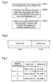
- Figure 4 shows a format of a remote control code outputted from the remote controller.
- the remote control code is 48 bits long, including a maker code of 16 bits and a device code of 12 bits.
- the format of the remote control code may be other than that shown in figure 4 .
- the remote control code is 48 bits long, the length may be other than 48 bits.
- the maker code and the device code are 16 bits and 12 bits long, respectively, the bit lengths thereof are not restricted thereto.
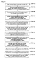
- the first half of the processing flow corresponds to the process steps from when the display 100 and the STBs are connected to when the maker codes and device codes are stored in the memory of the display.
- the display 100 and the first STB 110 are connected.
- the reception interface 107 of the display 100 and the transmission interface 1001 of the first STB 110 are connected by the HDMI cable 113.
- the controller 104 of the display 100 reads the maker code and device code of the first STB 110 from the first STB 110 via the device control line of the HDMI cable 113.
- STEP 3 the maker code and device code which have been read in STEP 2 are written in the memory 106 of the display 100 together with the reception interface number.
- the second STB 111 and the third STB 112 are also connected to the display 100 using the HDMI cables, and the maker codes and device codes of the respective STBs 111 and 112 are written in the memory 106 of the display 100 together with the reception interface numbers.
- the maker codes and device codes of the first STB 110 ⁇ the third STB 112 are stored in the memory 106 of the display 100, and a connected-device list table is created.
- the format of the maker code and device code stored in the connected-device list table is shown in figure 6
- the connected-device list table is shown in figure 7 .
- the first to third reception interfaces 107 ⁇ 109 correspond to reception interface numbers 1, 2, and 3, respectively.
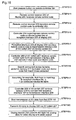
- the latter half of the processing flow according to the first embodiment corresponds to the process steps from when the user presses a remote control button to when the connected-device (STB here) is selected for video display and audio output.
- the user presses a button on the remote controller 101 the user wants to use. Then, the button to be pressed may be an arbitrary button or a specific button.
- the remote control receiver 103 of the display 100 receives the remote control code outputted from the remote controller 101.
- the remote control receiver 103 transfers the remote control code to the controller 104 of the display 100.
- the controller 104 extracts the maker code and the device code from the remote control code.
- the connected-device list table in the memory 106 is searched for a maker code and a device code that match the maker code and the device code extracted in STEP 7.
- the controller 104 controls the selector 105 to connect the signal outputted from the first reception interface 107 to the display section 102.
- STEP 11 transmission of AV data from the first STB 110 is started.
- the AV data is transmitted through the selector 105 to the display section 102.
- the display section 102 converts the AV data into analog data to perform video display and audio output.
- the display 100 when the first to third STBs 110 ⁇ 112 are connected to the display 100, the display 100 reads the maker codes and the device codes from the respective STBs 110 ⁇ 112 and creates the connected-device list table.
- the display 100 receives the remote control code outputted from the remote controller, and searches the connected-device list table for a maker code and a device code that match those included in the remote control code.
- the selector 105 is controlled so that the reception interface connected to the STB whose maker code and device code match those included in the remote control code is connected to the display section 102, and the AV data is transferred from the STB to the display 100, wherein the AV data is displayed and reproduced by the display section 102. Therefore, by only pressing the button on the remote controller aiming at the display, the connected-device corresponding to the remote controller is automatically selected, and the AV data from the selected connected-device can be automatically displayed on the display. As a result, it becomes unnecessary for the user to specially operate the remote controller to select the connected-device corresponding to the remote controller as in the conventional system, resulting in significant improvement in operability for the user.
- this second embodiment is different from the first embodiment only in that the AV switch is separated from the display in this second embodiment while the function of the AV switch is included in the display in the first embodiment.
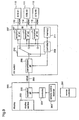
- Figure 9 is a diagram illustrating the construction of the AV system according to the second embodiment.
- the same reference numerals as those shown in figure 1 denote the same or corresponding constituents, and the description thereof is omitted.
- Reference numeral 200 denotes a display for displaying inputted video, and outputting audio.
- the display includes no AV switch.
- Reference numeral 201 denotes a remote controller that is associated with one of connected-devices.
- Reference numeral 202 denotes a display unit for displaying video and outputting audio, and for example, it comprises a CRT, or a liquid crystal panel, or a plasma display, and a speaker.
- Reference numeral 203 denotes a remote control receiver for receiving a signal from the remote controller 201.
- Reference numeral 204 denotes a controller of the display, for controlling the whole display, and for example, it is a CPU.
- Reference numeral 205 denotes a reception interface of the display, for receiving AV data from an AV switch 207 described later.
- Reference numeral 206 denotes an HDMI cable for connecting the display 200 and the AV switch 207, and transmitting the AV data from the AV switch 207 to the display 200, and exchanges control signals including a remote control code.
- Reference numeral 207 denotes an AV switch for selecting AV data from the respective connected-devices, and outputting the data to the display 200.
- Reference numeral 208 denotes a transmission interface of the AV switch 207, for outputting the AV data to the display 200.
- Reference numeral 209 denotes a controller of the AV switch 207, for controlling the AV switch 207.
- Reference numeral 210 denotes a selector for selecting video data and audio data from plural devices connected to the AV switch 207.
- Reference numeral 211 denotes a memory for holding a list table of the connected devices.
- This second embodiment is characterized in that the display and the AV switch are separated from each other, and the display and the AV switch are connected by the HDMI.
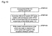
- the first half of the processing flow corresponds to the process steps from when the AV switch 207 and the STBs are connected to when the maker codes and device codes are stored in the memory of the AV switch.
- the AV switch 207 and the first STB 110 are connected. More specifically, the reception interface 107 of the AV switch 207 and the transmission interface 1001 of the first STB 110 are connected by the HDMI cable 113.
- the controller 209 of the AV switch 207 reads the maker code and device code of the first STB 110 from the first STB 110 through the device control line of the HDMI cable 113.
- STEP 103 the maker code and device code which have been read in STEP 102 are written in the memory 106 of the AV switch 207 together with the reception interface number.
- the second STB 111 and the third STB 112 are also connected to the AV switch 207 using the HDMI cables, respectively, and the maker codes and device codes of the STBs 111 and 112 are written in the memory 211 of the AV switch 207 together with the reception interface numbers.
- the maker codes and device codes of the first STB 110 ⁇ the third STB 112 are stored in the memory 211 of the AV switch 207, and the connected-device list table shown in figure 7 is created.
- the latter half of the processing flow corresponds to the process steps from when the user presses a remote control button to when a connected-device (STB here) is selected to perform video display and audio output.
- STEP 104 the user presses the button on the remote controller 201.
- the remote control receiver 203 of the display 200 receives the remote control code outputted from the remote controller 201.
- the remote control receiver 203 transfers the remote control code to the controller 204 of the display 200.
- the controller 204 superimposes the remote control code on the device control line of the reception interface 205 of the display.
- the reception interface 205 of the display transfers the remote control code to the transmission interface 208 of the AV switch 207 through the device control line.
- the controller 209 of the AV switch 207 receives the remote control code from the transmission interface 208, and extracts the maker code and device code.
- the connected-device list table in the memory 211 is searched for a maker code and a device code that match the maker code and the device code extracted in STEP 109.
- the controller 209 of the AV switch controls the selector 210 to connect the first reception interface 107 to the transmission interface 208.
- STEP 113 transmission of AV data from the first STB 110 is started.
- the AV data is transmitted to the display 200 through the AV switch 207.
- the display section 202 converts the AV data into analog data to perform video display and audio output.
- the AV switch 207 reads the maker codes and device codes from the respective STBs 110 ⁇ 112 to create a connected-device list table.
- the display 200 receives the remote control code outputted from the remote controller, and transfers it to the AV switch 207, wherein the connected-device list table is searched for a maker code and a device code that match the maker code and the device code included in the remote control code.
- the selector 210 is controlled so that the transmission interface 208 is connected to the reception interface that is connected to the STB whose maker code and device code match those included in the remote control code.
- AV data is transferred from the STB through the AV switch 207 to the display 200, wherein the AV data is displayed and reproduced by the display section 202. Therefore, by only pressing the button on the remote controller aiming at the display, the connected-device corresponding to the remote controller is automatically selected, and the AV data from the selected connected-device is automatically displayed on the display.
- the construction of the AV system according to the third embodiment is identical to that of the first embodiment ( figure 1 ), and the function of the AV switch is included in the display.
- the difference between the third embodiment and the first embodiment is that while in the first embodiment the maker code and device code are transferred from the connected-device such as an STB using the device control line of the HDMI, in this third embodiment the maker code and device code are superimposed on a portion of a video blanking period and transferred from the STB.
- the first half of the processing flow corresponds to the process steps from when the STBs and the display are connected to when the maker codes and device codes are stored in the memory of the display.
- STEP 201 the display 100 and the first STB 110 are connected.
- the controller 1002 of the first STB 110 reads the maker code and device code from the memory 1003.
- STEP 203 the maker code and device code read in STEP 202 are transferred to the transmission interface 1001.
- the transmission interface 1001 holds the maker code and device code.
- the first STB 110 performs AV decoding, and starts AV transmission from the transmission interface 1001 via the HDMI cable 113.
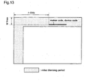
- the transmission interface 1001 superimposes the maker code and device code on a portion of the video blanking period, and transmits it to the display 100 via the HDMI cable 113. The manner of superimposing them on the blanking period will be described later.
- the first reception interface 107 of the display 100 receives the AV data from the HDMI cable 113.
- the first reception interface 107 of the display 100 extracts the maker code and device code superimposed on the video blanking period, and holds them. Further, the first reception interface 107 notifies the controller 104 of the display 100 that they are extracted.
- the controller 104 of the display 100 reads the maker code and device code from the first reception interface 107, and writes them in the memory 106 together with the reception interface number.
- the second STB 111 and the third STB 112 are also connected to the display 100 using the HDMI cables, and the maker codes and device codes of the respective STBs 111 and 112 are written in the memory 106 of the display 100 together with the reception interface numbers.
- the maker codes and device codes of the first STB 110 ⁇ the third STB 112 are stored in the memory 106 of the display 100, and a connected-device list table is created.
- the manner of superimposing the maker code and device code in STEP 206 is shown in figure 13 .
- the maker code of 16 bits and the device code of 12 bits are superimposed on a position at the m-th line in the vertical direction and the n-th dot in the horizontal direction from the upper left corner of the frame of the video blanking period.
- the temporal order in which the maker code and the device code are superimposed may be inverted.
- the transmission interface 1001 of the first STB 110 detects the upper left corner of the frame from a horizontal sync signal and a vertical sync signal outputted from the AV decoder 1008, and may superimpose the maker code and device code on a temporal position that is obtained by performing m-line count in the vertical direction and n-dot count in the horizontal direction.
- the first reception interface 107 restores the horizontal sync signal and the vertical sync signal of the video to detect the upper left corner of the frame, and may extract the maker code and device code which are superimposed at the m-th line in the vertical direction and the n-th dot in the horizontal direction.
- the latter half of the processing flow corresponds to the process steps from when the user presses a remote control button to when a connected-device (STB here) is selected to perform video display and audio output.
- STEP 210 the user presses the button on the remote controller 101.
- the remote control code outputted from the remote controller 101 is received by the remote control receive 103 of the display 100.
- the remote control receiver 103 transfers the remote control code to the controller 104 of the display 100.
- the controller 104 extracts the maker code and device code from the remote control code.
- the connected-device list table in the memory 106 is searched for a maker code and a device code that match the maker code and the device code extracted in STEP 213.
- the controller 104 controls the selector 105 to connect the signal outputted from the first reception interface 107 to the display section 102.
- AV data is transmitted to the display section 102 through the selector 105.
- the display section 102 converts the AV data into analog data to perform video display and audio output.
- each STB when the first to third STBs 110 ⁇ 112 are connected to the display 100, each STB superimposes its own maker code and device code on a portion of the video blanking period, and transmits them to the display 100.
- the display 100 extracts the maker code and device code from the video blanking period, and creates a connected-device list table.
- the display 100 receives the remote control code outputted from the remote controller, and searches the connected-device list table for a maker code and a device code that match the maker code and the device code included in the remote control code.
- the selector 105 is controlled so that the reception interface connected to the STB having the matching maker code and device code is connected to the display section 102, and AV data is transferred from the STB to the display 100, wherein the AV data is displayed and reproduced by the display section 102. Therefore, by only pressing the button on the remote controller aiming at the display, the connected-device corresponding to the remote controller is automatically selected, and the AV data from the selected connected-device can be automatically displayed on the display. As a result, it becomes unnecessary for the user to specially operate the remote controller to select the connected-device corresponding to the remote controller as in the conventional system, resulting in significant improvement in operability for the user.
- This fourth embodiment is a combination of the second embodiment and the third embodiment. That is, the AV system according to the fourth embodiment is characterized in that the display and the AV switch are separated from each other as in the second embodiment, and the maker code and device code are transmitted from the connected-device such as an STB during the video blanking period as in the third embodiment.
- the construction of the AV system according to this fourth embodiment is shown in figure 9 . Then, since figure 9 has already been described for the above-described second embodiment, repeated description is not necessary here.
- the first half of the processing flow (connected-device recognition method) according to this fourth embodiment is shown in figure 15 .
- the first half of the processing corresponds to the process steps from when the AV switch and the STBs are connected to when the maker codes and device codes are stored in the memory of the AV switch.
- STEP 301 the AV switch 207 and the first STB 110 are connected.
- the controller 1002 of the first STB 110 reads the maker code and device code from the memory 1003.
- STEP 303 the maker code and device code that are read in STEP 202 are transferred to the transmission interface 1001.
- the transmission interface 1001 holds the maker code and device code.
- the first STB 110 performs AV decoding, and starts AV transmission from the transmission interface 1001 through the HDMI cable 113.
- the transmission interface 1001 superimposes the maker code and device code on a portion of the video blanking period, and transmits them to the AV switch 207 through the HDMI cable 113.
- the first reception interface 107 of the AV switch 207 receives the AV data from the HDMI cable 113.
- the first reception interface 107 of the AV switch 207 extracts the maker code and device code that are superimposed on the video blanking period, and holds the codes. Further, the first reception interface 107 notifies the controller 209 of the AV switch 207 that they are extracted.
- the controller 209 of the AV switch 207 reads the maker code and device code from the first reception interface 107, and writes them in the memory 211 together with the reception interface numbers.
- the second STB 111 and the third STB 112 are also connected to the AV switch 207 using the HDMI cables, and the maker codes and device codes of the respective STBs 111 and 112 are written in the memory 211 of the AV switch 207 together with the reception interface numbers.
- the maker codes and device codes of the first STB 110 ⁇ the third STB 112 are stored in the memory 211 of the AV switch 207, and the connected-device list table is created.
- the latter half of the processing flow corresponds to the process steps from when the user presses a remote control button to when a connected-device (STB here) is selected to perform video display and audio output.
- STEP 310 the user presses the button on the remote controller 201.
- the remote control code outputted from the remote controller 201 is received by the remote control receiver 203 of the display 200.
- the remote control code is transferred from the remote control receiver 203 to the controller 204 of the display 200.
- the controller 204 superimposes the remote control code on the device control line of the reception interface 205 of the display 200.
- the reception interface 205 of the display transfers the remote control code to the transmission interface 208 of the AV switch 207 via the device control line.
- the controller 209 of the AV switch 207 receives the remote control code from the transmission interface 208, and extracts the maker code and device code.
- STEP 316 the connected-device list table in the memory 211 is searched for a maker code and a device code that match the maker code and the device code extracted in STEP 315.
- the controller 209 of the AV switch controls the selector 210 to connect the first reception interface 107 to the transmission interface 208.
- STEP 319 transmission of AV data from the first STB 110 is started.
- the AV data is transmitted to the display 200 via the AV switch 207.
- the display section 202 converts the AV data into analog data to perform video display and audio output.
- each STB when the first to third STBs 110 ⁇ 112 are connected to the AV switch 207 that is connected to the display 200 through the HDMI cable 206, each STB superimposes its own maker code and device code on a portion of the video blanking period to transmit them to the AV switch 207.
- the AV switch 207 extracts the maker code and device code from the video blanking period, and creates a connected-device list table.
- the display 200 receives the remote control code outputted from the remote controller, and transfers it to the AV switch 207.
- the connected-device list table is searched for a maker code and a device code that match the maker code and the device code included in the remote control code, and the selector 210 is controlled so that the reception interface connected to the STB having the matching maker code and device code is connected to the transmission interface 208, and then AV data is transferred from the STB through the AV switch 207 to the display 200, wherein the AV data is displayed and reproduced by the display section 202. Therefore, by only pressing the button on the remote controller aiming at the display, the connected-device corresponding to the remote controller is automatically selected, and the AV data from the selected connected-device can be automatically displayed on the display. As a result, it becomes unnecessary for the user to specially operate the remote controller to select the connected-device corresponding to the remote controller as in the conventional system, resulting in significant improvement in operability for the user.
- each connected-device starts transmission of AV data as the user presses the remote control button of the device, and the AV data is displayed on the display.
- video data such as OSD (ON Screen Display) may be transmitted and displayed.
- the selected connected-device may be operated according to the function of the pressed remote control button. For example, when a playback button on a remote controller of a DVD is pressed, a DVD corresponding to the remote controller is selected to start playback. When a button of a program table on a remote controller of an STB is pressed, an STB corresponding to the remote controller is selected to display the program table.
- an I2C bus of a DDC line of an HDMI cable may be used, or some of them may be used in combination.
- an AV system according to a fifth embodiment of the present invention will be described.
- the difference between the fifth embodiment and the first embodiment is that while in the first embodiment identification of each connected-device is carried out using the maker code and device code included in the remote control code, in this fifth embodiment identification of each connected-device is carried out using ID information other than the maker code and device code.
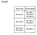
- a vendor ID list table shown in figure 19 and a device address list table shown in figure 20 are previously stored in the memory 106 of the display 100. Then, the vendor ID list table is used to obtain a vendor ID corresponding to a maker code, and the device address list table is used to obtain a device address corresponding to the device code.
- the display 100 inquires of the first STB 110 about the vendor ID, device address, and physical address of the first STB 110.
- the first STB 110 notifies the display 100 of the vendor ID, device address, and physical address that are stored in the memory 1003. Then, in the display 100, the contents of the notification from the first STB 110 is stored in the memory 106.
- the vendor ID, device address, and physical address of the first STB 110 are obtained. Further, as for the second STB 111 and the third STB 112, vendor IDs, device addresses, and physical addresses of the respective STBs are obtained in like manner as mentioned above.
- the memory 106 creates a connected-device list table on the basis of the contents obtained in the above-described processing.
- the connected-device list table is shown in figure 18 .
- the physical address of the first STB 110 connected to the first reception interface 107 is "1”
- the physical address of the second STB 111 connected to the second reception interface 108 is "2”
- the physical address of the third STB 112 connected to the third reception interface 109 is "3”.
- the physical addresses may be assigned "1", "2", "3" in chronological order in which the respective STBs are connected.
- STEP 401 the user presses the button on the remote controller 101.
- the remote control receiver 103 of the display 100 receives the remote control code outputted from the remote controller 101.
- the remote control receiver 103 transfers the remote control code to the controller 104.
- the controller 104 extracts the maker code and device code from the remote control code.
- STEP 405 the tables shown in figures 19 and 20 are searched for the vendor ID and the device address which correspond to the maker code and the device code extracted in STEP 404, respectively.
- the physical address is selected from the connected-device list table shown in figure 18 on the basis of the result of the search in STEP 405. For example, assuming that the vendor ID and the device address are vendor_id_1 and kiki_addr_1, respectively, the physical address "1" is selected. Then, the controller 104 controls the selector 105 to connect the first reception interface 107 and the display section 102.
- the connected-device corresponding to the remote controller can be automatically selected, and further, the operation of the corresponding connected-device can be controlled using the remote controller.
- the display 100 inquires the vendor IDs, device addresses, and physical addresses of the respective STBs, and creates a connected-device list table on the basis of the contents of notifications from the respective STBs 110 ⁇ 112.
- the display 100 receives the remote control code outputted from the remote controller, and obtains the vendor ID and device address corresponding to the maker code and device code included in the remote control code from the vendor ID list table and the device address list table that are previously stored.
- the display 100 obtains the physical address from the connected-device list table on the basis of the obtained vendor ID and device address, and controls the selector 105 so that the reception interface connected to the STB corresponding to the physical address is connected to the display section 102. Therefore, by only pressing the remote control button aiming at the display, the STB corresponding to the remote controller can be automatically selected. As a result, it becomes unnecessary for the user to specially operate the remote controller to select the connected-device corresponding to the remote controller as in the conventional system, resulting in significant improvement in operability for the user.
- this sixth embodiment is different from the fifth embodiment in that in the sixth embodiment the AV switch is separated from the display while the function of the AV switch is included in the display in the fifth embodiment.
- the vendor ID list table shown in figure 19 and the device address list table shown in figure 20 are previously stored in the memory 211 of the AV switch 207.
- the operation of the AV system according to this sixth embodiment will be described. Then, the method of recognizing the connected-devices connected to the AV switch 207 is almost identical in operation to the method described for the fifth embodiment, except that the created connected-device list table (shown in figure 18 ) is stored in the memory 211 of the AV switch 207.
- STEP 501 the user presses the button on the remote controller 201.
- the remote control receiver 203 of the display 200 receives the remote control code outputted from the remote controller 201.
- the remote control receiver 203 transfers the remote control code to the controller 204 of the display 200.
- the controller 204 superimposes the remote control code on the device control line of the reception interface 205 of the display.
- the reception interface 205 of the display transfers the remote control code to the transmission interface 208 of the AV switch 207 via the device control line.
- the controller 209 of the AV switch 207 receives the remote control code from the transmission interface 208, and extracts the maker code and device code.
- the controller 209 searches the tables shown in figures 19 and 20 for the vendor ID and device address corresponding to the maker code and device code extracted in STEP 506, respectively.
- the controller 209 selects the physical address from the connected-device list table shown in figure 18 on the basis of the result of the search in STEP 507. For example, assuming that the vendor ID and the device address are vendor_id_1 and kiki_addr_1, respectively, the physical address "1" is selected. Then, the controller 209 controls the selector 210 to connect the output of the first reception interface 107 to the transmission interface 208.
- the device corresponding to the remote controller can be automatically selected.
- the AV switch 207 inquires the vendor IDs, device addresses, and physical addresses of the respective STBs, and creates a connected-device list table on the basis of the contents of the notifications from the respective STBs 110 ⁇ 112.
- the display 200 receives the remote control code outputted from the remote controller, and transfers it to the AV switch 207.
- the vendor ID and device address corresponding to the maker code and device code included in the remote control code are obtained from the previously stored vendor ID list table and device address list table, and the physical address is obtained from the connected-device list table on the basis of the obtained vendor ID and device address, and then the selector 210 is controlled so that the reception interface connected to the STB corresponding to the physical address is connected to the transmission interface 208. Therefore, by only pressing the button on the remote controller aiming at the display, the STB corresponding to the remote controller can be automatically selected. As a result, it becomes unnecessary for the user to specially operate the remote controller to select the connected-device corresponding to the remote controller as in the conventional system, resulting in significant improvement in operability for the user.
- the difference between the seventh embodiment and the fifth embodiment is that while in the fifth embodiment the connected-device corresponding to the remote controller pressed by the user is identified at the display side and then the selector 105 is controlled, in this seventh embodiment the selector 105 is controlled from the connected-device side corresponding to the remote controller pressed by the user.
- STEP 601 the user presses the button on the remote controller 101.
- the remote control receiver 103 of the display 100 receives the remote control code outputted from the remote controller 101.
- the remote control receiver 103 transfers the remote control code to the controller 104.
- the controller 104 adds a header to the remote control code as shown in figure 24 , and transmits (broadcasts) the remote control code to all STBs in unison.
- each STB checks as to whether the remote control code received from the display 100 is directed to itself or not. That is, the STB extracts the maker code and device code from the remote control code, and compares them with its own maker code and device code that are previously stored. When there is matching, the STB decides that the remote control code is directed to itself.
- the STB which has decided that the remote control code is directed to itself outputs a switching instruction to the controller 104 of the display 100 through the device control line of the HDMI cable.
- the first STB 110 outputs a switching instruction to the display 100 through the device control line of the HDMI cable 113.
- the controller 104 controls the selector 105 according to the instruction from the first STB 110 to connect the first reception interface 107 to the display section 102.
- the selector 105 can be automatically controlled so as to select the device corresponding to the remote controller.
- the display 100 when the user presses the button on the remote controller, the display 100 receives the remote control code outputted from the remote controller, adds a header to the remote control code, and broadcasts the remote control code to all the STBs.
- Each STB checks as to whether the remote control code is directed to itself or not on the basis of the maker code and device code included in the remote control code, and the STB which decides that the remote control code is directed to itself outputs a switching instruction to the display 100. Therefore, by only pressing the button on the remote controller aiming at the display, the STB corresponding to the remote controller can be automatically selected. As the result, it becomes unnecessary for the user to specially control the remote controller to select the connected-device corresponding to the remote controller as in the conventional system, resulting in significant improvement in operability for the user.
- this eighth embodiment is different from the seventh embodiment in that the AV switch is separated from the display in this eighth embodiment while the function of the AV switch is included in the display in the seventh embodiment.
- the vendor ID list table shown in figure 19 and the device address list table shown in figure 20 are previously stored in the memory 211 of the AV switch 207.
- STEP 701 the user presses the button on the remote controller 201.
- the remote control receiver 203 of the display 200 receives the remote control code outputted from the remote controller 201.
- the remote control receiver 203 transfers the remote control code to the controller 204.
- the controller 204 superimposes the remote control code on the device control line of the reception interface 205.
- the reception interface 205 transfers the remote control code to the transmission interface 208 of the AV switch 207 through the device control line.
- the controller 209 of the AV switch 207 adds a header to the remote control code received by the transmission interface 208, as shown in figure 24 , and broadcasts the remote control code to all STBs.
- each STB checks as to whether the remote control code received from the AV switch 207 is directed to itself or not. That is, the STB extracts the maker code and device code from the remote control code, and compares them with its own maker code and device code that are previously stored. When there is matching, the STB decides that the remote control code is directed to itself.
- the STB which has decided that the remote control code is directed to itself outputs a switching instruction to the controller 209 of the AV switch 207 through the device control line of the HDMI cable.
- the first STB 110 outputs a switching instruction to the AV switch 207 through the device control line of the HDMI cable 113.
- the controller 209 controls the selector 210 according to the instruction from the first STB 110 to connect the first STB 110 to the transmission interface 208.
- the selector 210 can be automatically controlled so as to select the device corresponding to the remote controller.
- the display 200 receives the remote control code outputted from the remote controller and transfers it to the AV switch 207, and the AV switch 207 adds a header to the remote control code and broadcasts the remote control code to all the STBs.
- Each STB checks as to whether the remote control code is directed to itself or not on the basis of the maker code and device code included in the remote control code, and the STB which decides that the remote control code is directed to itself outputs a switching instruction to the AV switch 207. Therefore, by only pressing the button on the remote controller aiming at the display, the STB corresponding to the remote controller can be automatically selected. As the result, it becomes unnecessary for the user to specially operate the remote controller to select the connected-device corresponding to the remote controller as in the conventional system, resulting in significant improvement in operability for the user.
- each STB checks as to whether the remote control code is directed to itself or not, the STB uses the maker code and device code included in the remote control code.
- each STB may use the device address included in the header and the vendor ID corresponding to the maker code included in the remote control code for the checking.
- FIG. 1 The AV system according to this ninth embodiment is shown in figure 1 . Since figure 1 has already been described with respect to the first embodiment, repeated description is not necessary here.
- the display 100 performs recognition of the respective connected-devices using one of the methods described for the above-described first, third, and fifth embodiments.
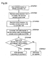
- STEP 801 the user presses the button on the remote controller 101.
- the remote control receiver 103 of the display 100 receives the remote control code outputted from the remote controller 101.
- the remote control receiver 103 transfers the remote control code to the controller 104.
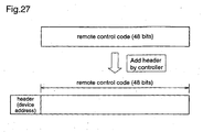
- the controller 104 adds a header to the remote control code as shown in figure 27 , and broadcast the remote control code to all STBs.
- each STB checks as to whether the output signal from the display 100 is directed to itself or not on the basis of the device address included in the header of the signal received from the display 100.
- the STB decides that the output signal is directed to itself, the STB goes to STEP 806 and executes the operation according to the command included in the remote control code.
- the STB decides that the output signal is not directed to itself, the STB goes to STEP 807 and does not execute the operation.
- the device corresponding to the remote controller can be caused to perform the operation desired by the user.
- the user when the user wants to display data of a desired connected-device on the display section 102, the user can change the display screen by the switching method described for any of the first, third, fifth, and seventh embodiments, using the remote controller corresponding to the desired connected-device.
- the display 100 when the user presses the button on the remote controller, the display 100 receives the remote control code outputted from the remote controller, adds a header to the remote control code, and broadcasts the remote control code to all the STBs.
- Each STB checks as to whether the remote control code is directed to itself or not on the basis of the device address included in the header of the output signal from the display 100, and the STB which decides that the remote control code is directed to itself performs the operation according to the command included in the remote control code. Therefore, the remote control operation for the video device can be performed with aiming the remote controller at the display.
- FIG. 9 The AV system according to the tenth embodiment is shown in figure 9 . Since figure 9 has already been described with respect to the second embodiment, repeated description is not necessary here.
- STEP 901 the user presses the button on the remote controller 201.
- the remote control receiver 203 of the display 200 receives the remote control code outputted from the remote controller 201.
- the remote control receiver 203 transfers the remote control code to the controller 204.
- the controller 204 superimposes the remote control code on the device control line of the reception interface 205.
- the reception interface 205 transfers the remote control code to the transmission interface 208 of the AV switch 207 through the device control line.
- the controller 209 of the AV switch 207 receives the remote control code from the transmission interface 208, adds a header to the remote control code as shown in figure 27 , and broadcasts the remote control code to all STBs.
- each STB checks as to whether the output signal from the AV switch 207 is directed to itself or not on the basis of the device address included in the header of the signal received from the AV switch 207.
- the STB decides that the output signal is directed to itself, the STB goes to STEP 908 and execute the operation according to the command included in the remote control code.
- the STB decides that the output signal is not directed to itself, the STB goes to STEP 909 and does not execute the operation.
- the device corresponding to the remote controller can be caused to execute the operation desired by the user.
- the user when the user wants to display data of a desired connected-device on the display section 202, the user can change the display screen by the switching method described for any of the second, fourth, sixth, and eighth embodiments, using the remote controller corresponding to the desired connected-device.
- the display 200 receives the remote control code outputted from the remote controller and transfers it to the AV switch 207. Then, the AV switch 207 adds a header to the remote control code, and broadcasts the remote control code to all the STBs.
- Each STB checks as to whether the remote control code is directed to itself or not on the basis of the device address included in the header of the output signal from the display 200, and the STB which decides that the remote control code is directed to itself performs the operation according to the command included in the remote control code. Therefore, the remote control operation for the video device can be performed with aiming at the display.
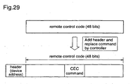
- the controller 104 of the display 100 or the controller 209 of the AV switch 207 adds the header to the remote control code, and broadcasts the remote control code.
- the controller 104 or 209 may add a device control command as well as the header to the remote control code, thereby to operate the corresponding connected-device according to the device control command.
- the device control command may be added to the top or the end of the remote control code, or, for example, it may be inserted in the remote control code by replacing the command portion of the remote control code with the device control command as shown in figure 29 .
- FIG. 1 The AV system according to this eleventh embodiment is shown in figure 1 . Since figure 1 has already been described with respect to the first embodiment, repeated description is not necessary here.
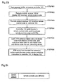
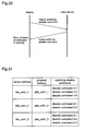
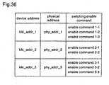
- the display 100 makes inquiries about switching disable commands to the respective connected-devices, and the connected-devices notify the display 100 of the switching disable commands which have previously been set by the makers. Then, the display 100 creates a list table of commands for disabling switching of the display screen on the basis of the contents of the notifications, as shown in figure 31 .
- This switching disable command list table is stored in the memory 106 of the display 100.
- the connected-devices may notify the switching disable commands as shown in figure 32 .
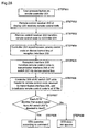
- STEP 1001 the user presses the button on the remote controller 101.
- the remote control receiver 103 of the display 100 receives the remote control code outputted from the remote controller 101.
- the remote control receiver 103 transfers the remote control code to the controller 104.
- the controller 104 extracts the maker code, device code, and command from the remote control code.
- the controller 104 searches the switching disable command list table for the command extracted in STEP 1004.
- the controller 104 goes to STEP 1006 and does not perform switching.
- the controller 104 goes to STEP 1007 and performs switching.
- the switching disable commands that have previously been set by the makers are obtained from the respective STBs before or after performing recognition of the connected-devices to create the switching disable command list table, and the selector 105 does not perform switching when the remote control code outputted from the remote controller includes a switching disable command on the switching disable command list table. Therefore, useless operation can be avoided when performing remote control operation in which switching of the display screen is not required, such as recording, fast forward, or fast reverse.
- figure 9 The AV system according to the twelfth embodiment is shown in figure 9 . Since figure 9 has already been described with respect to the above-described second embodiment, repeated description is not necessary here.
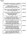
- the AV switch 207 makes inquiries about switching disable commands to the respective connected-devices, and the connected-devices notify the AV switch 207 of the switching disable commands which have previously been set by the makers. Then, the AV switch 207 creates a list table of commands for disabling switching of the display screen on the basis of the contents of the notifications, as shown in figure 31 , and stores the table in the memory 211 of the AV switch 207.
- the connected-devices may notify the switching disable commands.
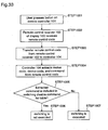
- STEP 1101 the user presses the button on the remote controller 201.
- the remote control receiver 203 of the display 200 receives the remote control code outputted from the remote controller 201.
- the remote control receiver 203 transfers the remote control code to the controller 204.
- the controller 204 superimposes the remote' control code on the device control line of the reception interface 205.
- the reception interface 205 transfers the remote control code to the transmission interface 208 of the AV switch 207 through the device control line.
- the controller of the AV switch 207 receives the remote control code from the transmission interface 208, and extracts the maker code, device code, and command from the remote control code.
- the controller 209 searches the switching disable command list table for the command extracted in STEP 1106.
- the controller 209 goes to STEP 1108 and does not perform switching. Further, when the switching disable command is not detected as the result of the search, the controller 209 goes to STEP 1109 and performs switching.
- the switching disable commands that have previously been set by the makers are obtained from the respective STBs before or after performing recognition of the connected-devices to create the switching disable command list table, and the selector 210 does not perform switching when the remote control code outputted from the remote controller includes a switching disable command on the switching disable command list table. Therefore, useless operation can be avoided when performing remote control operation in which switching of the display screen is not required, such as recording, fast forward, or fast reverse.
- a switching enable command list table as shown in figure 36 may be created to switch the display screen using a switching enable command. Thereby, the display screen can be automatically switched when executing playback, fast-forward playback, or fast-reverse playback.
- the AV system according to the present invention is useful as an AV system capable of performing remote control operation aiming at a display when a video device such as an STB, DVD, or VTR is connected to the display.
Landscapes
- Engineering & Computer Science (AREA)
- Signal Processing (AREA)
- Multimedia (AREA)
- Power Engineering (AREA)
- Computer Networks & Wireless Communication (AREA)
- Human Computer Interaction (AREA)
- Selective Calling Equipment (AREA)
- Details Of Television Systems (AREA)
- Two-Way Televisions, Distribution Of Moving Picture Or The Like (AREA)
Applications Claiming Priority (5)
| Application Number | Priority Date | Filing Date | Title |
|---|---|---|---|
| JP2002359065 | 2002-12-11 | ||
| JP2002359065 | 2002-12-11 | ||
| JP2003410250A JP4369214B2 (ja) | 2002-12-11 | 2003-12-09 | Avシステム |
| JP2003410250 | 2003-12-09 | ||
| PCT/JP2003/015763 WO2004054237A1 (ja) | 2002-12-11 | 2003-12-10 | Avシステム |
Publications (3)
| Publication Number | Publication Date |
|---|---|
| EP1571831A1 EP1571831A1 (en) | 2005-09-07 |
| EP1571831A4 EP1571831A4 (en) | 2008-07-16 |
| EP1571831B1 true EP1571831B1 (en) | 2010-02-24 |
Family
ID=32510648
Family Applications (1)
| Application Number | Title | Priority Date | Filing Date |
|---|---|---|---|
| EP03780691A Expired - Lifetime EP1571831B1 (en) | 2002-12-11 | 2003-12-10 | Av system |
Country Status (9)
Families Citing this family (95)
| Publication number | Priority date | Publication date | Assignee | Title |
|---|---|---|---|---|
| KR101049129B1 (ko) * | 2004-07-30 | 2011-07-15 | 엘지전자 주식회사 | 케이블 방송 수신기 및 그의 상태 정보 처리 방법 |
| KR101092438B1 (ko) * | 2004-08-05 | 2011-12-13 | 엘지전자 주식회사 | 케이블 방송 수신기 및 그의 진단 방법 |
| JP4817635B2 (ja) * | 2004-09-30 | 2011-11-16 | 株式会社東芝 | 画像表示装置及び画像表示方法 |
| US20060209892A1 (en) * | 2005-03-15 | 2006-09-21 | Radiospire Networks, Inc. | System, method and apparatus for wirelessly providing a display data channel between a generalized content source and a generalized content sink |
| US20060212911A1 (en) * | 2005-03-15 | 2006-09-21 | Radiospire Networks, Inc. | System, method and apparatus for wireless delivery of analog media from a media source to a media sink |
| US7499462B2 (en) * | 2005-03-15 | 2009-03-03 | Radiospire Networks, Inc. | System, method and apparatus for wireless delivery of content from a generalized content source to a generalized content sink |
| US20060209884A1 (en) * | 2005-03-15 | 2006-09-21 | Macmullan Samuel J | System, method and apparatus for automatic detection and automatic connection between a generalized content source and a generalized content sink |
| US20060209890A1 (en) * | 2005-03-15 | 2006-09-21 | Radiospire Networks, Inc. | System, method and apparatus for placing training information within a digital media frame for wireless transmission |
| WO2006108866A1 (en) * | 2005-04-15 | 2006-10-19 | Thomson Licensing | High-definition and single-definition digital television decoder |
| JP4655756B2 (ja) * | 2005-05-18 | 2011-03-23 | ソニー株式会社 | 遠隔操作装置、機器制御装置及び遠隔操作方法 |
| JP4216834B2 (ja) * | 2005-08-31 | 2009-01-28 | パナソニック株式会社 | 再生装置およびシステム |
| US11769398B2 (en) | 2005-09-08 | 2023-09-26 | Universal Electronics Inc. | System and method for widget-assisted setup of a universal remote control |
| JPWO2007037379A1 (ja) * | 2005-09-30 | 2009-04-16 | パナソニック株式会社 | 無線伝送システム |
| JP4811017B2 (ja) | 2005-12-27 | 2011-11-09 | パナソニック株式会社 | 映像音声システム、制御装置、出力装置、およびプログラム |
| US20140072309A9 (en) * | 2005-12-29 | 2014-03-13 | Monster Cable Products, Inc. | Infra-red repeater in power centers |
| JP4116071B2 (ja) | 2006-02-10 | 2008-07-09 | 松下電器産業株式会社 | 無線通信システム |
| US8401461B2 (en) | 2006-02-14 | 2013-03-19 | Panasonic Corporation | Wireless communication system for wirelessly transmitting setting information of display unit |
| CN101331771B (zh) | 2006-05-16 | 2010-07-28 | 索尼株式会社 | 通信系统、发送设备、接收设备和通信方法 |
| EP2026504B1 (en) * | 2006-05-19 | 2013-01-02 | Panasonic Corporation | Logic address allocation method |
| US20070298656A1 (en) * | 2006-06-22 | 2007-12-27 | Good Mind Industries Co., Ltd. | Switch apparatus for multiple high definition multimedia interface sources |
| US20090284656A1 (en) * | 2006-07-28 | 2009-11-19 | Sharp Kabushiki Kaisha | Display apparatus |
| JP4182997B2 (ja) | 2006-08-15 | 2008-11-19 | ソニー株式会社 | 伝送システム及び送受信装置 |
| EP2055048B1 (en) * | 2006-08-18 | 2010-05-05 | Koninklijke Philips Electronics N.V. | Decoupled connections |
| US9208679B2 (en) | 2006-09-05 | 2015-12-08 | Universal Electronics Inc. | System and method for configuring the remote control functionality of a portable device |
| US8812629B2 (en) | 2008-04-18 | 2014-08-19 | Universal Electronics Inc. | System and method for configuring the remote control functionality of a portable device |
| US8659400B2 (en) | 2006-09-05 | 2014-02-25 | Universal Electronics Inc. | System and method for configuring the remote control functionality of a portable device |
| US20080062305A1 (en) * | 2006-09-07 | 2008-03-13 | Renaud Lavoie | Combined multi-image and router apparatus |
| JP2008078961A (ja) * | 2006-09-21 | 2008-04-03 | Sharp Corp | 映像表示装置 |
| JP2008085729A (ja) * | 2006-09-28 | 2008-04-10 | Sharp Corp | 映像撮影装置,テレビジョン受像機,映像表示システム |
| JP4187037B2 (ja) | 2006-10-12 | 2008-11-26 | 船井電機株式会社 | 遠隔操作システム |
| JP2008104505A (ja) * | 2006-10-23 | 2008-05-08 | Sharp Corp | 表示システム、ゲームシステム、及びこれらを備えたゲーム表示システム |
| KR101303945B1 (ko) | 2006-10-25 | 2013-09-05 | 삼성전자주식회사 | 디지털 인터페이스의 신호출력장치 및 그 방법 |
| US8336773B2 (en) * | 2006-11-22 | 2012-12-25 | Verizon Patent And Licensing Inc. | Systems and methods for accessing media content using multiple user input devices |
| JP2008141562A (ja) * | 2006-12-04 | 2008-06-19 | Sharp Corp | 映像表示装置,映像処理装置 |
| US8266658B2 (en) | 2006-12-15 | 2012-09-11 | Panasonic Corporation | Wireless communication device automatically connecting for HDMI devices |
| KR101366316B1 (ko) * | 2007-01-09 | 2014-02-21 | 엘지전자 주식회사 | 신호 싱크 및 그의 동작 방법과 이를 제어하는 컴퓨터프로그램을 저장하는 컴퓨터로 읽을 수 있는 기록 매체 |
| US8810732B1 (en) * | 2007-02-09 | 2014-08-19 | Aliphcom | Auto-select algorithm for a high-definition multimedia interface switch |
| JP4917452B2 (ja) * | 2007-02-16 | 2012-04-18 | シャープ株式会社 | 表示装置及び表示システム |
| JP4388968B2 (ja) * | 2007-03-28 | 2009-12-24 | オンキヨー株式会社 | 画像再生システム及びそれに用いられる信号処理装置 |
| JP2008276067A (ja) * | 2007-05-02 | 2008-11-13 | Canon Inc | 映像表示装置及びその制御方法 |
| KR101385537B1 (ko) * | 2007-05-08 | 2014-04-17 | 삼성전자주식회사 | 어드레스 관리 방법 및 이를 적용한 영상기기 |
| JP5032202B2 (ja) * | 2007-05-23 | 2012-09-26 | 株式会社東芝 | 映像出力装置及び表示装置 |
| JP2008301232A (ja) * | 2007-05-31 | 2008-12-11 | Toshiba Corp | テレビジョン受像装置および機器制御方法 |
| US9124845B2 (en) * | 2007-07-19 | 2015-09-01 | At&T Intellectual Property I, L.P. | System and method to control media display functions |
| KR20090018471A (ko) * | 2007-08-17 | 2009-02-20 | 삼성전자주식회사 | 디스플레이장치 및 그 제어방법 |
| JP2009065267A (ja) * | 2007-09-04 | 2009-03-26 | Funai Electric Co Ltd | 電子機器 |
| EP2034663B1 (en) | 2007-09-07 | 2012-08-29 | Sony Corporation | Main electronic device for communicating within a network and method for operating a main electronic device for communicating within the network |
| JP2009094610A (ja) * | 2007-10-04 | 2009-04-30 | Sharp Corp | テレビジョン受信機及びテレビゲームシステム |
| US8832769B2 (en) * | 2007-10-16 | 2014-09-09 | Microsoft Corporation | Remote control based output selection |
| KR101404842B1 (ko) * | 2007-11-14 | 2014-06-09 | 엘지전자 주식회사 | 영상표시기기 및 사용 제한 방법 |
| JP4334590B2 (ja) | 2007-12-12 | 2009-09-30 | 株式会社東芝 | 情報再生装置及び情報再生方法 |
| JP5105171B2 (ja) | 2008-02-08 | 2012-12-19 | ソニー株式会社 | 表示装置、表示方法、供給装置、供給方法、およびプログラム、並びに制御システム |
| US8300153B2 (en) * | 2008-03-06 | 2012-10-30 | Advanced Testing Technologies, Inc. | Video selection display unit for multiple devices |
| JP4502031B2 (ja) * | 2008-03-18 | 2010-07-14 | 船井電機株式会社 | 映像表示装置 |
| US20090248909A1 (en) * | 2008-03-26 | 2009-10-01 | Sony Corporation | Method and Apparatus for Simulating Consumer Electronic Control Functionality for Devices |
| JP5079872B2 (ja) | 2008-03-27 | 2012-11-21 | パナソニック株式会社 | 無線通信装置 |
| JP4535161B2 (ja) | 2008-04-01 | 2010-09-01 | ソニー株式会社 | 電子機器、通信システム、通信方法、およびプログラム |
| US9088663B2 (en) | 2008-04-18 | 2015-07-21 | Universal Electronics Inc. | System for appliance control via a network |
| JP4357578B1 (ja) * | 2008-05-30 | 2009-11-04 | 株式会社東芝 | 音声データ処理装置および音声データ処理方法 |
| KR101558567B1 (ko) * | 2008-11-07 | 2015-10-07 | 엘지전자 주식회사 | 분리형 tv 시스템 및 그 제어 방법 |
| US8754992B1 (en) * | 2008-12-22 | 2014-06-17 | The Directv Group, Inc. | Interactive remote control programming method |
| US8418211B2 (en) | 2008-12-31 | 2013-04-09 | Echostar Technologies L.L.C. | Antenna diversity for control device applications |
| JP5494143B2 (ja) * | 2009-04-17 | 2014-05-14 | オンキヨー株式会社 | リモコン信号送受信システム、電子機器及びリモコン送信機 |
| JP4620161B2 (ja) | 2009-05-29 | 2011-01-26 | 株式会社東芝 | 情報提示装置および情報提示方法 |
| WO2011027957A1 (en) | 2009-09-01 | 2011-03-10 | Lg Electronics Inc. | Method for controlling external device and transmitting apparatus and receiving apparatus thereof |
| EP2474169B1 (en) | 2009-09-01 | 2019-02-20 | LG Electronics Inc. | Method for controlling external device and remote controller thereof |
| JPWO2011049181A1 (ja) * | 2009-10-23 | 2013-03-14 | シャープ株式会社 | マスター装置、マップテーブル更新方法、プログラムおよび記録媒体 |
| US9628845B2 (en) * | 2009-11-16 | 2017-04-18 | Echostar Technologies L.L.C. | Associating a control device with an electronic component |
| TW201123873A (en) * | 2009-12-24 | 2011-07-01 | Hon Hai Prec Ind Co Ltd | Television system, television and set top box thereof |
| JP5197650B2 (ja) * | 2010-02-23 | 2013-05-15 | 株式会社東芝 | 電子機器および表示制御方法 |
| JP2011188453A (ja) * | 2010-03-11 | 2011-09-22 | Sharp Corp | 電子機器システム、電子機器、操作方法、プログラム、及び記録媒体 |
| JP2012019556A (ja) * | 2010-03-31 | 2012-01-26 | Toshiba Corp | 制御システム及び電子機器 |
| US9786159B2 (en) | 2010-07-23 | 2017-10-10 | Tivo Solutions Inc. | Multi-function remote control device |
| US10162316B2 (en) * | 2010-09-08 | 2018-12-25 | Universal Electronics Inc. | System and method for providing an adaptive user interface on an electronic appliance |
| JP2012213131A (ja) * | 2011-03-24 | 2012-11-01 | Panasonic Corp | 入力切替装置 |
| JP5459262B2 (ja) * | 2011-05-20 | 2014-04-02 | ヤマハ株式会社 | スピーカ装置 |
| US9019435B2 (en) | 2011-09-22 | 2015-04-28 | Universal Electronics Inc. | System and method for configuring controlling device functionality |
| US11756412B2 (en) | 2011-10-28 | 2023-09-12 | Universal Electronics Inc. | Systems and methods for associating services and/or devices with a voice assistant |
| US10937308B2 (en) | 2011-10-28 | 2021-03-02 | Universal Electronics Inc. | System and method for optimized appliance control |
| US11295603B2 (en) | 2011-10-28 | 2022-04-05 | Universal Electronics Inc. | System and method for optimized appliance control |
| US9449500B2 (en) | 2012-08-08 | 2016-09-20 | Universal Electronics Inc. | System and method for optimized appliance control |
| JP5306489B2 (ja) | 2012-01-06 | 2013-10-02 | 株式会社東芝 | 端末、プログラムおよび機器操作制御方法 |
| JP6212882B2 (ja) | 2013-03-13 | 2017-10-18 | 株式会社リコー | 通信システム、送信装置及び受信装置並びに通信方法 |
| KR102082653B1 (ko) * | 2013-10-10 | 2020-03-02 | 삼성전자주식회사 | 디스플레이 장치 및 그 방법 |
| WO2015097884A1 (ja) * | 2013-12-27 | 2015-07-02 | 株式会社東芝 | 電子機器および制御方法 |
| CN105338385A (zh) * | 2014-07-16 | 2016-02-17 | 阿里巴巴集团控股有限公司 | 一种用于视频控制的方法与设备 |
| KR102406380B1 (ko) | 2016-01-05 | 2022-06-08 | 삼성전자주식회사 | 디스플레이 시스템, 디스플레이 장치 및 그의 제어 방법 |
| KR102407127B1 (ko) | 2016-01-05 | 2022-06-10 | 삼성전자주식회사 | 디스플레이 시스템, 디스플레이 장치 및 그의 제어 방법 |
| US20180131142A1 (en) * | 2016-11-10 | 2018-05-10 | Caavo Inc | Smart media cable |
| JP6432659B2 (ja) * | 2017-09-21 | 2018-12-05 | 株式会社リコー | 通信システム |
| KR102567329B1 (ko) | 2018-09-13 | 2023-08-17 | 삼성전자주식회사 | 전자 장치 및 이의 제어방법 |
| KR102582508B1 (ko) * | 2019-06-25 | 2023-09-26 | 엘지전자 주식회사 | 디스플레이 장치 |
| CN113163249B (zh) * | 2021-04-28 | 2022-08-19 | 深圳感臻智能股份有限公司 | 一种优化推荐码值的方法、装置及应用 |
| KR102746278B1 (ko) * | 2022-09-28 | 2024-12-26 | 엘지전자 주식회사 | 리모트 컨트롤러에 의해 제어되는 디스플레이 디바이스 및 그 제어 방법 |
| KR20250026024A (ko) * | 2023-08-16 | 2025-02-25 | 삼성전자주식회사 | 가상 인디케이터를 디스플레이하는 디스플레이 장치 및 그 제어 방법 |
Family Cites Families (21)
| Publication number | Priority date | Publication date | Assignee | Title |
|---|---|---|---|---|
| FR2449379A1 (fr) * | 1979-02-15 | 1980-09-12 | Scart | Systeme d'interconnexion dynamique audio-video |
| JPH07105895B2 (ja) * | 1986-06-02 | 1995-11-13 | ソニー株式会社 | 電子機器 |
| US4808992A (en) * | 1987-05-08 | 1989-02-28 | Rca Licensing Corporation | Component audio/video system with automatic turn-off of peripheral devices |
| JP2506969B2 (ja) * | 1988-08-03 | 1996-06-12 | 松下電器産業株式会社 | リモコン操作型送信機能付電子機器 |
| JP2773386B2 (ja) * | 1990-05-16 | 1998-07-09 | ソニー株式会社 | モニタ・テレビジョン装置 |
| JPH0583646A (ja) | 1991-09-24 | 1993-04-02 | Fujitsu General Ltd | Avセレクタ |
| JP3158364B2 (ja) * | 1992-10-13 | 2001-04-23 | ソニー株式会社 | 電子機器 |
| US5488357A (en) * | 1993-01-06 | 1996-01-30 | Sony Corporation | Remote controlling method and system feature starting method and controlling method for audio/visual system |
| FR2701845B1 (fr) | 1993-02-23 | 1995-04-07 | Oreal | Emulsion eau-dans-huile à usage cosmétique ou pharmaceutique. |
| JP2862160B2 (ja) * | 1993-05-31 | 1999-02-24 | ソニー株式会社 | 通信方式 |
| JPH0775029A (ja) * | 1993-09-03 | 1995-03-17 | Sony Corp | 複数のvtr操作インターフェイス |
| JP3612696B2 (ja) | 1996-12-18 | 2005-01-19 | ソニー株式会社 | 情報処理装置および方法、並びにリモートコントロールシステム |
| EP0920139A1 (de) * | 1997-11-28 | 1999-06-02 | Deutsche Thomson-Brandt Gmbh | Verfahren zur Steuerung von an ein zentrales Steuergerät angeschlossenen Geräten und entsprechendes Steuergerät |
| US6292230B1 (en) * | 1998-08-04 | 2001-09-18 | Thomson Licensing S.A. | Signal distribution apparatus with learning function |
| CA2310159C (en) * | 1999-05-31 | 2004-03-30 | Samsung Electronics Co., Ltd. | Method of controlling special playback mode of video signal reproducing apparatus |
| US6567011B1 (en) * | 1999-10-14 | 2003-05-20 | Universal Electronics Inc. | Media system and remote control for same |
| JP2002078040A (ja) * | 2000-08-29 | 2002-03-15 | Matsushita Electric Ind Co Ltd | 機器選択装置および機器選択方法 |
| KR100370024B1 (ko) * | 2000-08-31 | 2003-01-30 | 엘지전자 주식회사 | 리모트 콘트롤러를 갖는 영상기기 및 이 영상기기를 통해주변 기기들을 조작하는 방법 |
| JP4434467B2 (ja) * | 2000-11-01 | 2010-03-17 | キヤノン株式会社 | ユーザインタフェース制御装置 |
| JP2002271703A (ja) * | 2001-03-07 | 2002-09-20 | Sharp Corp | ビデオ無線送受信システム |
| US6961099B2 (en) * | 2001-10-16 | 2005-11-01 | Sony Corporation | Method and apparatus for automatically switching between analog and digital input signals |
-
2003
- 2003-12-09 JP JP2003410250A patent/JP4369214B2/ja not_active Expired - Fee Related
- 2003-12-10 AU AU2003289299A patent/AU2003289299A1/en not_active Abandoned
- 2003-12-10 WO PCT/JP2003/015763 patent/WO2004054237A1/ja active Application Filing
- 2003-12-10 BR BR0307563-0A patent/BR0307563A/pt not_active IP Right Cessation
- 2003-12-10 EP EP03780691A patent/EP1571831B1/en not_active Expired - Lifetime
- 2003-12-10 DE DE60331470T patent/DE60331470D1/de not_active Expired - Lifetime
- 2003-12-10 KR KR1020047012332A patent/KR100681098B1/ko not_active Expired - Fee Related
- 2003-12-11 US US10/732,305 patent/US7378984B2/en not_active Expired - Lifetime
-
2004
- 2004-08-10 MX MXPA04007742A patent/MXPA04007742A/es active IP Right Grant
Also Published As
| Publication number | Publication date |
|---|---|
| US7378984B2 (en) | 2008-05-27 |
| EP1571831A4 (en) | 2008-07-16 |
| JP4369214B2 (ja) | 2009-11-18 |
| DE60331470D1 (de) | 2010-04-08 |
| JP2004208290A (ja) | 2004-07-22 |
| AU2003289299A1 (en) | 2004-06-30 |
| WO2004054237A1 (ja) | 2004-06-24 |
| MXPA04007742A (es) | 2004-10-15 |
| BR0307563A (pt) | 2005-01-11 |
| KR20040081776A (ko) | 2004-09-22 |
| KR100681098B1 (ko) | 2007-02-08 |
| US20040143847A1 (en) | 2004-07-22 |
| EP1571831A1 (en) | 2005-09-07 |
Similar Documents
| Publication | Publication Date | Title |
|---|---|---|
| EP1571831B1 (en) | Av system | |
| CN101690180B (zh) | 显示系统和显示装置 | |
| EP2111041B1 (en) | Audio processing device, audio processing method, and program | |
| US7554614B2 (en) | Remote control system | |
| EP0821523B2 (en) | Digital television signal receiver | |
| US20140281999A1 (en) | Display device, two-way communication system and display information using method | |
| US7372508B2 (en) | Information outputting apparatus, information reporting method and information signal supply route selecting method | |
| USRE41707E1 (en) | Digital broadcasting receiver and method of controlling the same | |
| US20110134341A1 (en) | Digital broadcast receiver unit | |
| US20230254527A1 (en) | Image display device and method for controlling the same | |
| US20060001554A1 (en) | Video signal reception apparatus and video signal reception method | |
| JP2006019948A (ja) | 映像信号出力機器 | |
| JP4143675B1 (ja) | リモートコントロールシステムおよびコマンド転送方法 | |
| EP1152606B1 (en) | OSD system | |
| JP2008219932A (ja) | リモートコントロールシステムおよびコマンド転送方法 | |
| JP2006019809A (ja) | 映像信号受信装置及び映像信号受信方法 | |
| CN100534128C (zh) | Av系统 | |
| JP4693802B2 (ja) | 映像表示装置 | |
| KR100286277B1 (ko) | 다채널시스템의 입출력제어장치 | |
| KR20060125353A (ko) | 음성다중 수신 시스템에서의 자막 언어 절환 장치 및 그방법 | |
| JP2007329950A (ja) | 表示装置 | |
| KR20080054194A (ko) | 복합기기에서의 오디오신호 제어방법 및 그 장치 | |
| KR20080064038A (ko) | 디바이스 및 수신 장치를 갖는 시스템 및 그의 동작 방법 |
Legal Events
| Date | Code | Title | Description |
|---|---|---|---|
| PUAI | Public reference made under article 153(3) epc to a published international application that has entered the european phase |
Free format text: ORIGINAL CODE: 0009012 |
|
| 17P | Request for examination filed |
Effective date: 20040729 |
|
| AK | Designated contracting states |
Kind code of ref document: A1 Designated state(s): AT BE BG CH CY CZ DE DK EE ES FI FR GB GR HU IE IT LI LU MC NL PT RO SE SI SK TR |
|
| AX | Request for extension of the european patent |
Extension state: AL LT LV MK |
|
| DAX | Request for extension of the european patent (deleted) | ||
| RBV | Designated contracting states (corrected) |
Designated state(s): DE FR GB |
|
| RIN1 | Information on inventor provided before grant (corrected) |
Inventor name: NAGATA, KOICHIRO Inventor name: SUZUKI, HIDEKAZU Inventor name: NIO, YUTAKA Inventor name: YAMADA, MASAZUMIC/O MATSUSHITA ELECT. IND.CO.LTD |
|
| A4 | Supplementary search report drawn up and despatched |
Effective date: 20080612 |
|
| RIC1 | Information provided on ipc code assigned before grant |
Ipc: H04L 12/40 20060101ALI20080606BHEP Ipc: H04L 12/28 20060101ALI20080606BHEP Ipc: H04N 5/765 20060101ALI20080606BHEP Ipc: H04N 5/445 20060101AFI20080606BHEP Ipc: H04B 1/20 20060101ALI20080606BHEP |
|
| 17Q | First examination report despatched |
Effective date: 20080924 |
|
| RAP1 | Party data changed (applicant data changed or rights of an application transferred) |
Owner name: PANASONIC CORPORATION |
|
| GRAP | Despatch of communication of intention to grant a patent |
Free format text: ORIGINAL CODE: EPIDOSNIGR1 |
|
| RIN1 | Information on inventor provided before grant (corrected) |
Inventor name: NIO, YUTAKA Inventor name: NAGATA, KOICHIRO Inventor name: SUZUKI, HIDEKAZU Inventor name: YAMADA, MASAZUMIC/O MATSUSHITA ELECTRIC INDUSTRIAL |
|
| GRAS | Grant fee paid |
Free format text: ORIGINAL CODE: EPIDOSNIGR3 |
|
| GRAA | (expected) grant |
Free format text: ORIGINAL CODE: 0009210 |
|
| AK | Designated contracting states |
Kind code of ref document: B1 Designated state(s): DE FR GB |
|
| REG | Reference to a national code |
Ref country code: GB Ref legal event code: FG4D |
|
| REF | Corresponds to: |
Ref document number: 60331470 Country of ref document: DE Date of ref document: 20100408 Kind code of ref document: P |
|
| PLBE | No opposition filed within time limit |
Free format text: ORIGINAL CODE: 0009261 |
|
| STAA | Information on the status of an ep patent application or granted ep patent |
Free format text: STATUS: NO OPPOSITION FILED WITHIN TIME LIMIT |
|
| 26N | No opposition filed |
Effective date: 20101125 |
|
| PGFP | Annual fee paid to national office [announced via postgrant information from national office to epo] |
Ref country code: FR Payment date: 20130107 Year of fee payment: 10 |
|
| REG | Reference to a national code |
Ref country code: FR Ref legal event code: ST Effective date: 20140829 |
|
| PG25 | Lapsed in a contracting state [announced via postgrant information from national office to epo] |
Ref country code: FR Free format text: LAPSE BECAUSE OF NON-PAYMENT OF DUE FEES Effective date: 20131231 |
|
| PGFP | Annual fee paid to national office [announced via postgrant information from national office to epo] |
Ref country code: DE Payment date: 20191126 Year of fee payment: 17 |
|
| PGFP | Annual fee paid to national office [announced via postgrant information from national office to epo] |
Ref country code: GB Payment date: 20191206 Year of fee payment: 17 |
|
| REG | Reference to a national code |
Ref country code: DE Ref legal event code: R119 Ref document number: 60331470 Country of ref document: DE |
|
| GBPC | Gb: european patent ceased through non-payment of renewal fee |
Effective date: 20201210 |
|
| PG25 | Lapsed in a contracting state [announced via postgrant information from national office to epo] |
Ref country code: DE Free format text: LAPSE BECAUSE OF NON-PAYMENT OF DUE FEES Effective date: 20210701 Ref country code: GB Free format text: LAPSE BECAUSE OF NON-PAYMENT OF DUE FEES Effective date: 20201210 |