EP1570893B1 - Filteranordnung mit abgedichtetewabenstruktur und herstellungsverfahren dafür - Google Patents
Filteranordnung mit abgedichtetewabenstruktur und herstellungsverfahren dafür Download PDFInfo
- Publication number
- EP1570893B1 EP1570893B1 EP03778781A EP03778781A EP1570893B1 EP 1570893 B1 EP1570893 B1 EP 1570893B1 EP 03778781 A EP03778781 A EP 03778781A EP 03778781 A EP03778781 A EP 03778781A EP 1570893 B1 EP1570893 B1 EP 1570893B1
- Authority
- EP
- European Patent Office
- Prior art keywords
- plugging
- face
- honeycomb structure
- protruding portion
- cells
- Prior art date
- Legal status (The legal status is an assumption and is not a legal conclusion. Google has not performed a legal analysis and makes no representation as to the accuracy of the status listed.)
- Expired - Lifetime
Links
Images


Classifications
-
- B—PERFORMING OPERATIONS; TRANSPORTING
- B01—PHYSICAL OR CHEMICAL PROCESSES OR APPARATUS IN GENERAL
- B01D—SEPARATION
- B01D46/00—Filters or filtering processes specially modified for separating dispersed particles from gases or vapours
- B01D46/24—Particle separators, e.g. dust precipitators, using rigid hollow filter bodies
- B01D46/2403—Particle separators, e.g. dust precipitators, using rigid hollow filter bodies characterised by the physical shape or structure of the filtering element
- B01D46/2418—Honeycomb filters
- B01D46/2425—Honeycomb filters characterized by parameters related to the physical properties of the honeycomb structure material
- B01D46/244—Honeycomb filters characterized by parameters related to the physical properties of the honeycomb structure material of the plugs
-
- B—PERFORMING OPERATIONS; TRANSPORTING
- B01—PHYSICAL OR CHEMICAL PROCESSES OR APPARATUS IN GENERAL
- B01D—SEPARATION
- B01D39/00—Filtering material for liquid or gaseous fluids
- B01D39/14—Other self-supporting filtering material ; Other filtering material
- B01D39/20—Other self-supporting filtering material ; Other filtering material of inorganic material, e.g. asbestos paper, metallic filtering material of non-woven wires
- B01D39/2055—Carbonaceous material
- B01D39/2058—Carbonaceous material the material being particulate
- B01D39/2062—Bonded, e.g. activated carbon blocks
-
- B—PERFORMING OPERATIONS; TRANSPORTING
- B01—PHYSICAL OR CHEMICAL PROCESSES OR APPARATUS IN GENERAL
- B01D—SEPARATION
- B01D46/00—Filters or filtering processes specially modified for separating dispersed particles from gases or vapours
-
- B—PERFORMING OPERATIONS; TRANSPORTING
- B01—PHYSICAL OR CHEMICAL PROCESSES OR APPARATUS IN GENERAL
- B01D—SEPARATION
- B01D46/00—Filters or filtering processes specially modified for separating dispersed particles from gases or vapours
- B01D46/0001—Making filtering elements
-
- B—PERFORMING OPERATIONS; TRANSPORTING
- B01—PHYSICAL OR CHEMICAL PROCESSES OR APPARATUS IN GENERAL
- B01D—SEPARATION
- B01D46/00—Filters or filtering processes specially modified for separating dispersed particles from gases or vapours
- B01D46/24—Particle separators, e.g. dust precipitators, using rigid hollow filter bodies
- B01D46/2403—Particle separators, e.g. dust precipitators, using rigid hollow filter bodies characterised by the physical shape or structure of the filtering element
- B01D46/2418—Honeycomb filters
- B01D46/2425—Honeycomb filters characterized by parameters related to the physical properties of the honeycomb structure material
- B01D46/24491—Porosity
-
- B—PERFORMING OPERATIONS; TRANSPORTING
- B01—PHYSICAL OR CHEMICAL PROCESSES OR APPARATUS IN GENERAL
- B01D—SEPARATION
- B01D46/00—Filters or filtering processes specially modified for separating dispersed particles from gases or vapours
- B01D46/24—Particle separators, e.g. dust precipitators, using rigid hollow filter bodies
- B01D46/2403—Particle separators, e.g. dust precipitators, using rigid hollow filter bodies characterised by the physical shape or structure of the filtering element
- B01D46/2418—Honeycomb filters
- B01D46/2451—Honeycomb filters characterized by the geometrical structure, shape, pattern or configuration or parameters related to the geometry of the structure
- B01D46/2459—Honeycomb filters characterized by the geometrical structure, shape, pattern or configuration or parameters related to the geometry of the structure of the plugs
-
- B—PERFORMING OPERATIONS; TRANSPORTING
- B01—PHYSICAL OR CHEMICAL PROCESSES OR APPARATUS IN GENERAL
- B01D—SEPARATION
- B01D46/00—Filters or filtering processes specially modified for separating dispersed particles from gases or vapours
- B01D46/24—Particle separators, e.g. dust precipitators, using rigid hollow filter bodies
- B01D46/2403—Particle separators, e.g. dust precipitators, using rigid hollow filter bodies characterised by the physical shape or structure of the filtering element
- B01D46/2418—Honeycomb filters
- B01D46/2451—Honeycomb filters characterized by the geometrical structure, shape, pattern or configuration or parameters related to the geometry of the structure
- B01D46/2486—Honeycomb filters characterized by the geometrical structure, shape, pattern or configuration or parameters related to the geometry of the structure characterised by the shapes or configurations
- B01D46/249—Quadrangular e.g. square or diamond
-
- B—PERFORMING OPERATIONS; TRANSPORTING
- B01—PHYSICAL OR CHEMICAL PROCESSES OR APPARATUS IN GENERAL
- B01D—SEPARATION
- B01D46/00—Filters or filtering processes specially modified for separating dispersed particles from gases or vapours
- B01D46/24—Particle separators, e.g. dust precipitators, using rigid hollow filter bodies
- B01D46/2403—Particle separators, e.g. dust precipitators, using rigid hollow filter bodies characterised by the physical shape or structure of the filtering element
- B01D46/2418—Honeycomb filters
- B01D46/2451—Honeycomb filters characterized by the geometrical structure, shape, pattern or configuration or parameters related to the geometry of the structure
- B01D46/2486—Honeycomb filters characterized by the geometrical structure, shape, pattern or configuration or parameters related to the geometry of the structure characterised by the shapes or configurations
- B01D46/2496—Circular
-
- B—PERFORMING OPERATIONS; TRANSPORTING
- B28—WORKING CEMENT, CLAY, OR STONE
- B28B—SHAPING CLAY OR OTHER CERAMIC COMPOSITIONS; SHAPING SLAG; SHAPING MIXTURES CONTAINING CEMENTITIOUS MATERIAL, e.g. PLASTER
- B28B11/00—Apparatus or processes for treating or working the shaped or preshaped articles
-
- B—PERFORMING OPERATIONS; TRANSPORTING
- B28—WORKING CEMENT, CLAY, OR STONE
- B28B—SHAPING CLAY OR OTHER CERAMIC COMPOSITIONS; SHAPING SLAG; SHAPING MIXTURES CONTAINING CEMENTITIOUS MATERIAL, e.g. PLASTER
- B28B11/00—Apparatus or processes for treating or working the shaped or preshaped articles
- B28B11/003—Apparatus or processes for treating or working the shaped or preshaped articles the shaping of preshaped articles, e.g. by bending
- B28B11/006—Making hollow articles or partly closed articles
- B28B11/007—Using a mask for plugging
-
- F—MECHANICAL ENGINEERING; LIGHTING; HEATING; WEAPONS; BLASTING
- F01—MACHINES OR ENGINES IN GENERAL; ENGINE PLANTS IN GENERAL; STEAM ENGINES
- F01N—GAS-FLOW SILENCERS OR EXHAUST APPARATUS FOR MACHINES OR ENGINES IN GENERAL; GAS-FLOW SILENCERS OR EXHAUST APPARATUS FOR INTERNAL-COMBUSTION ENGINES
- F01N3/00—Exhaust or silencing apparatus having means for purifying, rendering innocuous, or otherwise treating exhaust
- F01N3/02—Exhaust or silencing apparatus having means for purifying, rendering innocuous, or otherwise treating exhaust for cooling, or for removing solid constituents of, exhaust
- F01N3/021—Exhaust or silencing apparatus having means for purifying, rendering innocuous, or otherwise treating exhaust for cooling, or for removing solid constituents of, exhaust by means of filters
- F01N3/0211—Arrangements for mounting filtering elements in housing, e.g. with means for compensating thermal expansion or vibration
-
- F—MECHANICAL ENGINEERING; LIGHTING; HEATING; WEAPONS; BLASTING
- F01—MACHINES OR ENGINES IN GENERAL; ENGINE PLANTS IN GENERAL; STEAM ENGINES
- F01N—GAS-FLOW SILENCERS OR EXHAUST APPARATUS FOR MACHINES OR ENGINES IN GENERAL; GAS-FLOW SILENCERS OR EXHAUST APPARATUS FOR INTERNAL-COMBUSTION ENGINES
- F01N3/00—Exhaust or silencing apparatus having means for purifying, rendering innocuous, or otherwise treating exhaust
- F01N3/02—Exhaust or silencing apparatus having means for purifying, rendering innocuous, or otherwise treating exhaust for cooling, or for removing solid constituents of, exhaust
- F01N3/021—Exhaust or silencing apparatus having means for purifying, rendering innocuous, or otherwise treating exhaust for cooling, or for removing solid constituents of, exhaust by means of filters
- F01N3/022—Exhaust or silencing apparatus having means for purifying, rendering innocuous, or otherwise treating exhaust for cooling, or for removing solid constituents of, exhaust by means of filters characterised by specially adapted filtering structure, e.g. honeycomb, mesh or fibrous
- F01N3/0222—Exhaust or silencing apparatus having means for purifying, rendering innocuous, or otherwise treating exhaust for cooling, or for removing solid constituents of, exhaust by means of filters characterised by specially adapted filtering structure, e.g. honeycomb, mesh or fibrous the structure being monolithic, e.g. honeycombs
-
- B—PERFORMING OPERATIONS; TRANSPORTING
- B01—PHYSICAL OR CHEMICAL PROCESSES OR APPARATUS IN GENERAL
- B01D—SEPARATION
- B01D2239/00—Aspects relating to filtering material for liquid or gaseous fluids
- B01D2239/04—Additives and treatments of the filtering material
- B01D2239/0471—Surface coating material
- B01D2239/0478—Surface coating material on a layer of the filter
-
- B—PERFORMING OPERATIONS; TRANSPORTING
- B01—PHYSICAL OR CHEMICAL PROCESSES OR APPARATUS IN GENERAL
- B01D—SEPARATION
- B01D2239/00—Aspects relating to filtering material for liquid or gaseous fluids
- B01D2239/06—Filter cloth, e.g. knitted, woven non-woven; self-supported material
- B01D2239/065—More than one layer present in the filtering material
-
- B—PERFORMING OPERATIONS; TRANSPORTING
- B01—PHYSICAL OR CHEMICAL PROCESSES OR APPARATUS IN GENERAL
- B01D—SEPARATION
- B01D2239/00—Aspects relating to filtering material for liquid or gaseous fluids
- B01D2239/08—Special characteristics of binders
- B01D2239/086—Binders between particles or fibres
-
- B—PERFORMING OPERATIONS; TRANSPORTING
- B01—PHYSICAL OR CHEMICAL PROCESSES OR APPARATUS IN GENERAL
- B01D—SEPARATION
- B01D2239/00—Aspects relating to filtering material for liquid or gaseous fluids
- B01D2239/10—Filtering material manufacturing
-
- B—PERFORMING OPERATIONS; TRANSPORTING
- B01—PHYSICAL OR CHEMICAL PROCESSES OR APPARATUS IN GENERAL
- B01D—SEPARATION
- B01D46/00—Filters or filtering processes specially modified for separating dispersed particles from gases or vapours
- B01D46/24—Particle separators, e.g. dust precipitators, using rigid hollow filter bodies
- B01D46/2403—Particle separators, e.g. dust precipitators, using rigid hollow filter bodies characterised by the physical shape or structure of the filtering element
- B01D46/2418—Honeycomb filters
- B01D46/2451—Honeycomb filters characterized by the geometrical structure, shape, pattern or configuration or parameters related to the geometry of the structure
-
- B—PERFORMING OPERATIONS; TRANSPORTING
- B01—PHYSICAL OR CHEMICAL PROCESSES OR APPARATUS IN GENERAL
- B01D—SEPARATION
- B01D46/00—Filters or filtering processes specially modified for separating dispersed particles from gases or vapours
- B01D46/24—Particle separators, e.g. dust precipitators, using rigid hollow filter bodies
- B01D46/2403—Particle separators, e.g. dust precipitators, using rigid hollow filter bodies characterised by the physical shape or structure of the filtering element
- B01D46/2418—Honeycomb filters
- B01D46/2498—The honeycomb filter being defined by mathematical relationships
-
- F—MECHANICAL ENGINEERING; LIGHTING; HEATING; WEAPONS; BLASTING
- F01—MACHINES OR ENGINES IN GENERAL; ENGINE PLANTS IN GENERAL; STEAM ENGINES
- F01N—GAS-FLOW SILENCERS OR EXHAUST APPARATUS FOR MACHINES OR ENGINES IN GENERAL; GAS-FLOW SILENCERS OR EXHAUST APPARATUS FOR INTERNAL-COMBUSTION ENGINES
- F01N2260/00—Exhaust treating devices having provisions not otherwise provided for
- F01N2260/18—Exhaust treating devices having provisions not otherwise provided for for improving rigidity, e.g. by wings, ribs
-
- F—MECHANICAL ENGINEERING; LIGHTING; HEATING; WEAPONS; BLASTING
- F01—MACHINES OR ENGINES IN GENERAL; ENGINE PLANTS IN GENERAL; STEAM ENGINES
- F01N—GAS-FLOW SILENCERS OR EXHAUST APPARATUS FOR MACHINES OR ENGINES IN GENERAL; GAS-FLOW SILENCERS OR EXHAUST APPARATUS FOR INTERNAL-COMBUSTION ENGINES
- F01N2330/00—Structure of catalyst support or particle filter
- F01N2330/06—Ceramic, e.g. monoliths
-
- Y—GENERAL TAGGING OF NEW TECHNOLOGICAL DEVELOPMENTS; GENERAL TAGGING OF CROSS-SECTIONAL TECHNOLOGIES SPANNING OVER SEVERAL SECTIONS OF THE IPC; TECHNICAL SUBJECTS COVERED BY FORMER USPC CROSS-REFERENCE ART COLLECTIONS [XRACs] AND DIGESTS
- Y02—TECHNOLOGIES OR APPLICATIONS FOR MITIGATION OR ADAPTATION AGAINST CLIMATE CHANGE
- Y02T—CLIMATE CHANGE MITIGATION TECHNOLOGIES RELATED TO TRANSPORTATION
- Y02T10/00—Road transport of goods or passengers
- Y02T10/10—Internal combustion engine [ICE] based vehicles
- Y02T10/12—Improving ICE efficiencies
-
- Y—GENERAL TAGGING OF NEW TECHNOLOGICAL DEVELOPMENTS; GENERAL TAGGING OF CROSS-SECTIONAL TECHNOLOGIES SPANNING OVER SEVERAL SECTIONS OF THE IPC; TECHNICAL SUBJECTS COVERED BY FORMER USPC CROSS-REFERENCE ART COLLECTIONS [XRACs] AND DIGESTS
- Y10—TECHNICAL SUBJECTS COVERED BY FORMER USPC
- Y10T—TECHNICAL SUBJECTS COVERED BY FORMER US CLASSIFICATION
- Y10T428/00—Stock material or miscellaneous articles
- Y10T428/24—Structurally defined web or sheet [e.g., overall dimension, etc.]
- Y10T428/24149—Honeycomb-like
- Y10T428/24157—Filled honeycomb cells [e.g., solid substance in cavities, etc.]
Definitions
- the present invention relates to a filter assembly and a method of manufacturing the assembly, particularly including a honeycomb structure having plugging portions, which does not easily break and which is capable of enhancing durability and which is usable in a filter such as a diesel particulate filter (DPF).
- a filter such as a diesel particulate filter (DPF).
- DPF diesel particulate filter
- a honeycomb structure When a honeycomb structure is used as a filter such as a DPF, in general, as shown in FIGS. 11(a) to (c) , the structure is used in the form of a plugged honeycomb structure 1 having: porous partition walls 2 arranged in such a manner as to form a plurality of cells 3 each extending from one end face 42 to the other end face 44 in an axial direction; an outer peripheral wall 7 which surrounds outer peripheries of the partition walls 2; and plugging portions 4 which are arranged in such a manner as to plug the cells 3 in either end face.
- a fluid to be treated flows into the cell from one end face 42, and is discharged from the other end face 44 via another cell 3 through the porous partition wall 2.
- the partition wall 2 constitutes a filter to capture particulate matters.
- the plugged honeycomb structure is stored in a can member 20 formed of a metal in a state in which a mat 24 formed of a ceramic is wound around an outer peripheral wall of the structure.
- the structure is fixed by an annular fixing member 22 disposed in the can member and formed of a metal, attached to an automobile or the like, and used in some case (see, e.g., Japanese Patent Application Laid-Open No. 8-281034 ).
- the plugged honeycomb structure for use in this application has requirements that the structure does not easily break by vibration, pressure loss is small, and resistance to thermal shock is satisfactory.
- a plugged honeycomb structure in which a protruding portion is formed on plugging portions, protruding in a tapered shape toward an upstream side from the end face of the cell, as a method of preventing rapid increase of the pressure loss by deposition of the particulate matters (see, e.g., Japanese Patent Application Laid-Open No. 2002-309922 ).
- JP-A-4 301 115 describes a honeycomb structure which has, at one end, ceramic sealing plugs which project from the end face of the honeycomb.
- the plugging portions extend a very large distance from the ends of the cells.
- Honeycombs are regenerated by raising the honeycomb to a high temperature, 'burning' captured particulates. That is done using a microwave heater. Particulates are concentrated at the end of the honeycomb which has the protruding plugging portions.
- the plugging portions are provided with a large surface area, so that they absorb a large amount of microwave radiation.
- WO 00 48807 describes a method of plugging honeycomb cells involving introducing a sealant material into pre-selected honeycomb cell openings by capillary action to form a plug on said pre-selected cell openings.
- WO 00 48807 seeks to address the problem of fluid leakage around the plugging portions.
- the protruding plugging portions are formed in a product which is unfired.
- the materials used for plugging are exemplified as epoxies, silicones, waxes, thermoplastic polymers, and inorganic/organic mixes.
- the plugging material is not a ceramic materials alone. The protruding portion of the plugs will burn out if the honeycomb structure is fired to integrate the material used for the plugs and the partition walls of the honeycomb structure,
- EP 1 293 241 describes plugged-honeycomb structures having plugging portions which may project from the end of the honeycomb structure.
- EP 1 293 241 states that at least some of the plugs except for those near the outer peripheral wall preferably project from the end surfaces of the partition walls by 0.01 to 5 mm.
- the pitch of the partition walls is preferably 2.54 mm or less. The relative porosity of the partition walls and the plugging portions is not discussed.
- US-A-4 573 896 describes a method and various apparatuses related to making honeycomb structures, the cells of which are selectively charged with a plugging or other flowable material. Solid coverings are applied over the end faces of the honeycomb structure and openings are created through the covering. The sealing or other flowable material is charged through the openings formed in the covering into the underlying cells. US-A-4 573 896 says that the porosity of the plugs should be "no greater" than that of the partition walls. It mentions using a foaming plugging material. It does not mention protrusion of the sealing portions.
- EP 1 245 360 describes a plugging method for a ceramic honeycomb body, that is said not to create clearance around plug members closing cell end portions. End faces of the ceramic honeycomb body are immersed in a plug member slurry while cell end portions not to be provided with the plug member are covered with a masking material. It is then dried and heated. The plug member slurry contains ceramic particles, a foaming material and water or an oil solvent. EP 1 245 360 does not mention protrusion of the plug members. It does not mention relative porosity of the plugging portions and the partition walls.
- EP 0 295 343 describes a method for producing a ceramic honeycomb structural body having selectively sealed open end surfaces, which comprises steps of attaching a film or mask on an open end surface of a ceramic honeycomb structural body, introducing a ceramic sealing material into throughholes of said honeycomb body through apertures bored at selected positions of the film or mask, and drying to solidify the sealing material followed by sintering.
- EP 0 295 343 does not mention protrusion of the sealing portions.
- US 4,293,357 describes a ceramic honeycomb filter produced by adhering a film on an opening end surface of a ceramic honeycomb body, boring holes at a given portion of the film or adhering a film bored at a given portion to an opening end surface of the ceramic honeycomb body, charging a sealing material into the channels of the ceramic honeycomb body through the bores in the film to seal an end portion of the given channels, and then sealing another end surface of the remaining channels with the sealing material in the same manner.
- US 4,293,357 does not mention protrusion of the sealing portions.
- EP 0 677 478 describes a method for sealing or plugging selected open cells or channels of a sinterable honeycomb structure.
- the plugging material is applied from the bottom up using gravity and optionally, vibration forces.
- a plugging material containing glass and foaming agent is also described which upon heating melts and crystallizes. Upon heating, the foaming agent causes the glass to foam and expand.
- EP 0 677 478 does not mention protrusion of the plugging portions.
- EP 1 418 032 describes a method for plugging cells of a honeycomb structure and a method for manufacturing a honeycomb plugged structure.
- a plugging member molded in a predetermined shape is inserted into the cell, and the plugging member is bonded to the peripheral partition walls to form a plug portion.
- EP 1 418 032 does not mention the relative porosity of the plugging portions and the partition walls, or the height by which the plug portions may protrude.
- An object of the present invention is to provide a filter assembly including a fired plugged honeycomb structure in which a pressure loss is reduced from a viewpoint different from that of the above-described proposal and whose breakage does not easily occur, and a method of manufacturing the assembly.
- the present inventor has studied cracks that can be generated in the vicinity of an outer peripheral wall in detail in order to solve the problem.
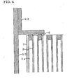
- a tip is formed substantially on the same face as an end face 42. Therefore, as shown in FIG. 12 , in a case where the plugged honeycomb structure is fixed in a can member 20 by an annular fixing member 22 fixed to the can member 20, an end portion of a partition wall is brought into direct contact with an end portion of the outer peripheral wall and the fixing member 22.
- a fluid to be treated flows into the can member 20, such as an exhaust gas at high temperature, the can member 20 and the fixing member 22 are heated and expanded.
- the fixing member 22 moves toward an outer periphery while pressing the end face 42. Therefore, in a case where large heat is applied, it is supposed that cracks are generated in the end face in the vicinity of the outer peripheral wall by a stress received during this movement.
- a metal wire is knitted into a net shape to form a wire mesh ring (not shown) into a ring shape, and the ring is sometimes disposed as a cushion material between the fixing member 22 and the end face 42.
- the wire mesh ring is brought into direct contact with the end face 42, and further bites in an opening of a cell which is not plugged.
- the fixing member moves, the wire mesh moves, and a stress is applied to the partition wall of a portion bitten by the wire mesh to induce cracks,
- the fluid to be treated does not flow into the cell in the vicinity of the outer peripheral wall, the cell cannot perform a function of a filter, and pressure loss increases.
- the fluid to be treated at high temperature does not flow into the cell in the vicinity of the outer peripheral wall, a temperature difference is made from an inner cell into which the fluid to be treated at the high temperature flows, and it is supposed that cracks are easily generated by thermal shock.
- a filter assembly comprising a can member and, fixed inside the can member by a fixing member, a fired plugged honeycomb structure comprising: partition walls arranged in such a manner as to form a plurality of cells extending from one end face to the other end face in an axial direction; an outer peripheral wall which surrounds an outer periphery of the partition walls; and plugging portions disposed in such a manner as to plug the cells in either end face, at least some of the plugging portions arranged in at least the vicinity of the outer peripheral wall having a portion protruding from the end face, characterized in that a tip of the protruding portion has a flat face or has a curved face of curvature radius of 0.1 mm or more; the porosity of the protrud
- the tip of the protruding portion is preferably substantially flat or has the moderate curved face.
- the structure preferably has a plugging portion including a protruding portion including a portion whose sectional shape crossing the axial direction at right angles is substantially circular.
- the structure also preferably has a plugging portion including a protruding portion including a portion whose sectional shape crossing the axial direction at right angles is a substantially polygonal shape, and the substantially polygonal shape further preferably has a shape whose corner portion has been cut into a linear or curved shape.
- the structure preferably has a plugging portion including a protruding portion whose sectional shape parallel to the axial direction is a substantially quadrangular shape, and the substantially quadrangular shape is further preferably a shape whose corner portion has been cut into a linear or curved shape.
- a maximum height from the end face to the tip of each protruding portion is preferably substantially equal. Porosity of the protruding portion is preferably smaller than that of another portion of the plugged honeycomb structure.
- a method of manufacturing a filter assembly comprising: preparing a honeycomb structure comprising porous partition walls arranged in such a manner as to form a plurality of cells extending from one end face to the other end face in an axial direction and an outer peripheral wall which surrounds an outer periphery of the partition walls, a plugging step of plugging at least some of the cells in either end face, a firing step, and a canning step in which the fired plugged honeycomb structure is fixed in a can member by a fixing member; wherein the plugging step includes: a masking sub-step of disposing a film on an end face in such a manner as to mask some of the cells; and a filling sub-step of filling predetermined cells which are not masked with a plugging material; wherein the filling sub-step includes: filling the cells with the plugging material up to a height which is not less than a height equal to that of an upper face of the film to form portions protruding
- the plugging material is preferably applied at least twice. Further in the filling sub-step, the plugging material is also preferably applied once. Furthermore, the plugging material is a slurry including a liquid, and the liquid is preferably a liquid which does not substantially penetrate into the partition wall.
- the film is disposed in such a manner as to cover all the cells, a hole is preferably made in a portion of the film, corresponding to a predetermined cell, and a hole is further preferably made in such a manner that periphery of the hole is raised in a thickness direction of the film.
- the plugging material is a slurry containing a liquid, and viscosity of the slurry is 10 to 1000 dPa•s, further preferably 100 to 600 dPa/s.
- the plugging material is also preferably a slurry containing at least one type selected from a group consisting of a powdered organic material derived from plant, powdered synthetic resin, powdered carbon-based material, hollow synthetic resin, solid normal-temperature liquid or gas material, high-melting material, porous material, and hollow inorganic material. After filling the cell with the plugging material, volume of the plugging material is expanded, and the protruding portion is protruded from the filter end face.
- a plugged honeycomb structure and a method of manufacturing the structure will be described hereinafter in detail based on a specific embodiment.
- the present invention is not limited to the following embodiment. It is to be noted that a section crossing an axial direction (for example, an axial direction shown in FIG. 1(a) ) at right angles will be hereinafter referred to as an orthogonal section, and a section parallel to the axial direction will be referred to as a parallel section.
- a plugged honeycomb structure 1 in the present invention has: partition walls 2 arranged in such a manner as to form a plurality of cells 3 extending from one end face 42 to the other end face 44 through an axial direction; an outer peripheral wall 7 which surrounds an outer periphery of the partition wall 2; and plugging portions 4a, 4b arranged in such a manner as to plug the cell 3 in either end face.
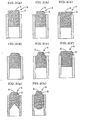
- An important characteristic of the present invention lies in that, as shown in FIG. 1(b) , at least some of plugging portions 4a arranged in the vicinity of the outer peripheral wall 7 protrude from the end face 42, and a tip 6 of a protruding portion 5 is substantially flat as shown in FIGS. 2(a) to (h) , or has a moderate curved face as shown in FIGS. 3(a) to (e) .
- a fluid to be treated can flow into the cell in the vicinity of the outer periphery, and pressure losses can be reduced. Furthermore, a temperature difference can be reduced between the cell in the vicinity of the outer periphery and the inner cell, and a possibility of the crack by thermal stress can be reduced.
- the protruding portion in the present invention needs to simply protrude, and further a tip needs to have a flat face or have a curved face of curvature radius of 0.1 mm or more.
- a tip when the protruding portion 5 has a conical or pyramid shape as shown in FIG. 13 , an excessive stress is applied to the tip at a time when the structure is fixed by the fixing member, and this causes the cracks in the protruding portion or the vicinity of the outer peripheral wall.
- the tip 6 is substantially flat, it is meant that the tip of the protruding portion has a substantially flat portion.
- the flat portion is preferably as flat as possible, and flatness is preferably about 0.05 mm or less.
- the flatness of 0.05 mm mentioned herein is the same definition as that of a flatness prescribed by JIS-B0021, means that a contour of the face exists in a space having a width of 0.05 mm, and means that an actually measured flatness value of the flat face which is an object is 0.05 mm or less.
- plugging portions protruding height from a filter end face is about 0.005 to 0.02 mm.
- a case where the actually measured flatness value of the protruding portion is 0.01 mm is included in a range of the flatness of 0.05 mm or less.
- An area of this flat portion may be usually small, but is preferably 5% or more of a sectional area of one cell, that is, a sectional area of plugging portions main body, more preferably 20% or more from a viewpoint that the fixing member be smoothly moved.
- the smaller flatness of the flat portion is better, and the flatness is preferably 0.05 mm or less.
- the flatness may increase to about 2 mm by the protruding height of the plugging portion tip and the area of the flat portion, but is practically preferably about 0.1 or less, further 0.5 mm or less, when considering a preparing property, and positional precision or stability of the fixing member.
- the flatness in the whole protruding portion is also important, and is
- a curvature radius in the plugging tip portion is R 0.1 mm or more, preferably R 0.5 mm or more, further preferably R 1 mm or more.
- a substantially flat tip is a preferable configuration.
- a parallel sectional shape is a substantially quadrangular shape such as a substantially rectangular shape and a substantially trapezoidal shape.
- the substantially quadrangular shape includes a quadrangular shape whose corner portion has been cut off in addition to a quadrangular shape.
- the quadrangular shape has a parallel sectional shape whose corner portion has been cut into a linear or curved shape, and this is preferable from a viewpoint of suppressing the cracks in the vicinity of the outer peripheral wall by smooth movement of the fixing member. That is, the tip preferably has a shape whose corner portion has been chamfered. As a preferable specific example of the tip having a moderate curved face, the tip has one domed shape as shown in FIGS. 3(a) to (d) , and the tip has two or more domed shapes as shown in FIG. 3(e) .
- the protruding portion preferably includes a portion having a substantially circular sectional shape as shown in FIG. 6(a) , or a substantially polygonal sectional shape as shown in FIG. 6(b) , and preferably includes a portion having a sectional shape similar to that of the cell.
- the sectional shape of the cell is a substantially polygonal shape such as a substantially quadrangular shape
- the protruding portion preferably has a shape which starts from the same shape as the sectional shape of the cell and which changes into a polygonal shape having more corner portions or a substantially circular shape toward the tip.
- the substantially circular shape include an elliptic shape, a race track shape and the like in addition to the circular shape
- the substantially polygonal shape includes a shape whose corner portion has been cut into a linear or curved shape in addition to a usual polygonal shape.
- the substantially polygonal shape is preferable whose corner portion has been cut into the linear or curved shape from a viewpoint of suppressing chipping of the corner portion.
- the protruding portion 5 there is a height from the end face 42 of a plugged honeycomb structure shown in FIG. 5(a) , that is, a maximum height h of the protruding portion.
- a maximum height h of the protruding portion is excessively large, the protruding portion easily chips.
- the maximum height h of the protruding portion is 20 ⁇ m or more, preferably 0.2 mm or more, especially further preferably 0.5 mm or more, and is not more than a cell pitch length, preferably 80% or less of the cell pitch length, further especially preferably 50% or less.
- the maximum height of each protruding portion may differ. However, the maximum height of the protruding portion of each plugging portion disposed in at least the in the vicinity of the outer peripheral wall is substantially equal, and this is preferable from a viewpoint that stress of the fixing member be scattered. From a viewpoint of ease of preparation, the maximum heights of the protruding portions of all the plugging portions are preferably substantially equal.
- the height of the protruding portion is less than 20 ⁇ m. In this case, the flatness is 0.02 mm, and the protruding portion is preferably 5 ⁇ m or more at minimum.
- Porosity of the protruding portion of the plugging portion is set to be smaller than that of another portion of the plugged honeycomb structure to densify the structure. Accordingly, effects can be expected that the protruding portion develops strength sufficiently bearing the contact with the fixing member, and the surface of the protruding portion is smoothened to reduce friction with the fixing member.
- a slurry component of a plugging agent is adjusted beforehand, and the structure is fired in such a manner that the porosity of the plugging portion is set to be smaller than that of a honeycomb structure main body.
- the protruding portion may be coated with a component such as cordierite, silica, and alumina.
- a Ti-based or W-based hard material may be flame-sprayed to the surface of the protruding portion. That is, the porosity of the whole plugging portion is reduced, accordingly the porosity of the protruding portion is set to be smaller than that of the partition wall, and it is a preferable configuration to reduce the porosity of the only protruding portion in the plugging portion.
- the plugging portions which plug the cells arranged in the vicinity of the outer peripheral wall need to have the above-described protruding portions, and it is not essential that all the plugging portions for plugging the cells arranged in the vicinity of the outer peripheral wall have the above-described protruding portions.
- all the plugging portions for plugging the cells arranged in the vicinity of the outer peripheral wall preferably have the above-described protruding portions. From a viewpoint that the plugging portion be easily formed, all the plugging portions preferably have the above-described protruding portions.
- the vicinity of the outer peripheral wall include the cell adjacent to the outer peripheral wall, a range of the vicinity changes with a width of the fixing member, and the range is preferably within 5 mm from the outer peripheral wall, further preferably within 20 mm.
- the plugging portions arranged not only in the vicinity of the outer peripheral portion but also in a portion other than the vicinity of the outer peripheral portion have the protruding portions according to the present invention, that is, even when the protruding portions exist over the whole region of the end face of the honeycomb structure, there is not any practical problem.
- the protruding portion of the plugging portion is preferably formed over the whole region of the end face of the honeycomb structure.
- a contact area with the exhaust gas increases, and therefore heat exchange is improved between the plugging portion and the exhaust gas.
- the plugging portion has a larger volume and a larger heat capacity as compared with a peripheral partition wall portion, a follow-up property at exhaust gas temperature is low, a temperature difference is large between the plugging portion and the partition wall portion, and thermal stress is easily generated.
- the heat exchange is improved between the plugging portion and the exhaust gas, it can be expected that the temperature difference is reduced, and the thermal stress is suppressed.
- the protruding portion of the plugging portion is preferably formed over the whole region of the end face of the honeycomb structure. Therefore, the protruding portions are preferably disposed in all the plugging portions in the honeycomb structure end face, but this is not necessarily required, and the protruding portions may be appropriately disposed in accordance with a use environment at a practical use time. It is to be noted that the honeycomb structure in the present invention has resistance to the above-described collision with the foreign matters, and an effect of reducing the thermal stress. Therefore, even in a use mode in which any fixing member is not used, for example, a canning structure in which a can member is held without using any fixing member, the plugged honeycomb structure in the present invention can be effectively used.
- the plugged honeycomb structure is sometimes placed on a face of a base or floor at a transfer time of the plugged honeycomb structure or a handling time.
- the corner portion (end portion of the outer peripheral wall) of the end face outer periphery chips in some case.
- the corner portion of the end face outer periphery is not brought into direct contact with a lower surface, and there is an effect of preventing the chipping.
- either lower end face preferably has the effect of preventing the chipping.
- FIGS. 1(a), (b) partition walls 2 arranged in such a manner as to form a plurality of cells 3 extending from one end face 42 to the other end face 44 through an axial direction; an outer peripheral wall 7 which surrounds the outer periphery of the partition wall 2; and plugging portions 4 arranged in such a manner as to plug the cells 3 in either end face 42, 44.
- the orthogonal sectional shape of the plugged honeycomb structure can be appropriately determined, for example, from a circular shape, elliptical shape, race track shape, quadrangular shape and the like in accordance with application or installation place.
- the orthogonal sectional shape of the cell may be a substantially polygonal shape such as a polygonal shape like a triangular shape, quadrangular shape, or hexagonal shape, or a substantially circular shape such as a circular shape and an elliptical shape.
- a cell density may be set to, for example, about 6 to 2000 cells/square inch (0.9 to 311 cells/cm 2 ), preferably 50 to 1000 cells/square inch (7.8 to 155 cells/cm 2 ).
- the adjacent cells 3 have plugging portions 4a, 4b in mutually opposite end faces, and the plugging portions are arranged in such a manner that the respective end faces 42, 44 form a checkered pattern.
- the plugging portion there is not any special restriction as to materials of the plugging portion, partition wall, and outer peripheral wall, but a ceramic or a metal is preferable, the ceramic is especially preferable from a viewpoint of heat resistance or the like.
- the partition wall and the outer peripheral wall is preferably porous.
- an elastic member is preferably disposed such as a ceramic-formed mat between the can member and the outer peripheral wall.
- This method includes a plugging step of plugging at least some of the cells 3 in either end face in a honeycomb structure 10 having the partition walls 2 arranged in such a manner as to form a plurality of cells 3 extending from one end face 42 to the other end face 44 through the axial direction as shown in FIGS. 7(a), (b) .
- the plugging step includes a masking sub-step, and a filling sub-step.
- a film 12 is disposed in the end face in such a manner as to mask some cells, that is, cells in which any plugging portion is not formed in the end face.
- the film 12 may be attached to the end face in a state in which a hole 13 is made in a portion of the film 12, corresponding to the predetermined cell in which the plugging portion is formed in the end face, that is, the portion of the film disposed on the predetermined cell.
- the hole 13 is made in the predetermined cell in which the plugging portion is formed. This is preferable because the hole is correctly made in the targeted cell.
- the hole 13 is made in the film 12 after disposing the film in this manner, the hole is made in such a manner that the periphery of the hole 13 is raised in a thickness direction of the film, for example, as shown in FIG. 9(a) , and this is preferable in that a plugging material can be applied in such a manner as to form a protruding portion having a sufficient height in the filling sub-step.
- An example of a specific method of making the hole in this manner includes a method in which the film is heated in such a manner as to be molten toward the outside from a center of the hole to make the hole. Further specifically, a predetermined position is preferably irradiated with laser light or the like to make the hole.
- the film preferably has an adhesive layer in such a manner that the film is sufficiently fixed after disposed on the end face.
- the film has a substrate layer and the adhesive layer, the substrate layer is formed of a polymer material such as polyester, polyolefin, and halogenated polyolefin, and the adhesive layer is preferably formed of an acryl-based adhesive material.
- the film has a thickness of about 10 to 100 ⁇ m from viewpoints of strength and ease of making the hole.
- the cell in which the hole has been made is filled with a plugging material 14.
- a conventional filling step as shown in FIG. 14(a) , the plugging material 14 formed into a water-containing slurry is poured into a slurry container 16, an end face 42 of a masked honeycomb structure 10 is immersed into the plugging material 14 formed into the slurry, and the predetermined cells are filled with the plugging material 14.
- a liquid in the slurry with which the cells are filled leaches in the porous partition wall or the outer peripheral wall.
- a tip 15 of the slurry moves toward the cell from the upper face of the film, and the only plugging portion can be formed having a height equal to or lower than that of the end face of the honeycomb structure.
- a plugging material 14 is charged up to a height which is not less than a height equal to that of an upper face 17 of the film, and therefore the plugging portion having the protruding portion can be formed.
- the upper face of the film means a face of the film on a side opposite to the honeycomb structure.
- the cell can be filled up to the height which is not less than that of the upper face of the film by two applications, but the plugging material may be applied three or more times.
- the slurry is poured beforehand in a container for the plugging, the film in which the holes have been made in a zigzag shape is attached beforehand to the honeycomb structure, the structure is fixed to a movable portion of a press with a chuck, the structure is pressed into the container under a pressure of 0.01 to 5 MPa at a speed of 0.1 to 10 mm/sec., and the slurry in the container is injected into the cell from the made holes.
- the honeycomb structure is chucked in such a manner that the honeycomb end face extends in parallel with the container.
- the honeycomb structure is sealed in such a manner as to prevent a plugging material slurry from being leaked from an outer peripheral portion of the structure.
- the sealing may be unnecessary in a case where a slurry amount is small in order to set a plugging depth to be small.
- Viscosity of the plugging material slurry is preferably in a range of 10 to 1000 dPa ⁇ s.
- the viscosity is in this range, the slurry is easily held in the cell in a case where the cell is filled with the slurry, and a predetermined plugging portion can be easily formed. Since the slurry does not become excessively hard, the cell can be easily filled with the slurry.
- the cell partition wall can be prevented from being pushed/broken at a slurry filling time.
- the viscosity of the slurry is further preferably in a range of 100 to 600 dPa ⁇ s.
- the viscosity is in this range, it is possible to preferably suppress a phenomenon in which the liquid in the slurry charged into the cell leaches in the porous partition wall or the outer peripheral wall, kink of the plugging material is reduced, and the number of filling times can be reduced to enhance productivity. Even each corner of the cell is easily filled with the slurry, and a gap can be easily prevented from being generated between a cell corner and the plugging portion.
- the gap When the gap is generated between the cell corner and the plugging portion, a capturing performance of the filter degrades. However, when a capturing efficiency is in an allowable range, the gap may be sometimes generated between the cell corner and the plugging portion in order to reduce the pressure loss of the filter or to discharge an ash component deposited in the cell from the gap. Accordingly, the viscosity of the plugging material slurry is intentionally increased in order to suppress rise of the pressure loss by long-term deposition of the ash component, and the gap is generated.
- a liquid which does not substantially penetrate the partition wall is used in a liquid component in the slurry plugging material, and accordingly the tip of the plugging material is prevented from being moved.
- the cell can be filled with the plugging material up to the upper face of the film by one filling.
- the liquid does not substantially penetrate it is meant that the liquid only penetrates to such an extent that a length for moving the tip of the plugging material toward the cell is about 50 ⁇ m or less, preferably 30 ⁇ m or less, further preferably 10 ⁇ m or less.
- This liquid that is, a plugging agent slurry is a liquid having high viscosity, and specifically a water content in the slurry is lowered as much as possible, or a thickening agent can be added as an auxiliary agent to the plugging agent slurry to adjust the viscosity.
- a material having a water-absorbing or retaining property is added to the plugging material slurry to reduce a drying speed of the slurry. Since the water-absorbing or retaining material holds the water content, it is possible to suppress a phenomenon in which the water content in the slurry charged into the cell leaches in the porous partition wall or the outer peripheral wall by addition of this material.
- the water-absorbing or retaining material is more preferable, but the material does not necessarily have any water-absorbing or retaining property.
- the material preferably decomposes, flies/scatters, and disappears in drying or firing after the plugging/filling, but may not decompose, fly/scatter, or disappear as long as plugging portions characteristic is not adversely influenced during or after the firing, or may react with the plugging material.
- Examples of the material which decomposes, flies/scatters, and disappears include: powdered organic materials derived from plant, such as flour, starch, and walnut shell; powdered synthetic resins such as PET, PMMA, phenol resin, polyethylene, and urethane; powdered carbon materials such as graphite, cokes, coal, activated charcoal, and tubular carbon; hollowed synthetic resins such as foaming resin, non-foamed foaming resin, and water-absorbing polymer; and solid liquid or gas materials at normal temperature, such as ice and dry ice.
- powdered organic materials derived from plant such as flour, starch, and walnut shell
- powdered synthetic resins such as PET, PMMA, phenol resin, polyethylene, and urethane
- powdered carbon materials such as graphite, cokes, coal, activated charcoal, and tubular carbon
- hollowed synthetic resins such as foaming resin, non-foamed foaming resin, and water-absorbing polymer
- Examples of the material which does not decompose, fly/scatter, or disappear or which reacts with the plugging material include: high-melting materials such as alumina, mullite, aluminum titanate, zirconia, silicon nitride, silicon carbide, titania, tungsten carbide, and molybdenum; porous materials such as silica gel and zeolite; and hollow inorganic materials such as fly ash balloon, silastic balloon, and silica beads.
- the high-melting material mentioned here is a material having a melting point which is higher than a firing temperature of a plugging material main component.
- nonoxide-based materials are preferable such as silicon nitride and silicon carbide as the high-melting materials because the materials are stable in the firing of cordierite in an oxide atmosphere at about 1400°C.
- a shape of the material may be not only particulate but also fibrous, and the powder means that both the particulate and fibrous materials are contained.
- the material is preferably hollow rather than solid in treatment of a generated gas at a decomposition, flying/scattering, and disappearing time. These materials may be used alone or compounded. Added amounts of these materials are appropriately determined based on settings of viscosity of the plugging slurry and plugging material porosity after the firing, and therefore are not especially restricted.
- the hollow synthetic resins like the foaming resin, non-foamed foaming resin, and water-absorbing polymer, and porous materials such as silica gel have water-absorbing properties, and are preferable for the above-described reason.
- a material is added which causes volume expansion by thermal treatment or the like. Accordingly, the plugging material in the cell causes the volume expansion, the plugging portion protrudes from the filter end face, and the protruding portion can be easily formed.
- the non-foamed foaming resin is added to the plugging material beforehand, and the cell is filled with the plugging material and thermally treated at 100 to 250°C, the non-foamed resin foams, and the volume of the plugging portion expands.
- the water-absorbing synthetic resin or urethane is added to the plugging material beforehand, the cell is filled with the plugging material, and thereafter the water content is added to the plugging material, the volume of the water-absorbing synthetic resin or urethane is expanded to expand the volume of the plugging portion.
- bubbles are intentionally generated in the plugging material slurry, and the cell is filled with the slurry in such a manner that the bubbles remain in the plugging portions, the porosity of the plugging portion can be raised.
- the porosity of the plugging portion increases, the thermal capacity of the plugging portion is lowered, and burning of particulate matters (PM) in the filter is promoted. Furthermore, even in a case where a catalyst is carried in the filter, the PM is oxidized/burnt utilizing activity of the catalyst, and toxic components in the exhaust gas are treated, there is an effect that the thermal capacity of the plugging portion is lowered to thereby enhance the catalyst activity.
- filter temperature does not easily rise especially in the cell in the vicinity of the plugging portion because of high thermal capacity of the plugging portion, and the catalyst activity drops.
- the rigidity of the plugging portion is lowered, accordingly the rigidity difference is reduced, and the resistance to thermal shock of the filter is enhanced. Stress concentration in the vicinity of the plugging portion can be relaxed in a case where the filter outer peripheral surface is grasped by a mat or the like.
- the porosity of the plugging portion is raised, sufficient permeability is imparted to the plugging portion, the exhaust gas can pass through the plugging portion, and there is an effect of reducing the pressure loss of the filter.
- the rigidity of the honeycomb substrate is brought close to that of the plugging portion in a stage of manufacturing the filter, cracks can be reduced in the vicinity of the plugging portion at a firing time.
- the holes are made in such a manner that the peripheries of the holes 13 are raised in the film thickness direction, accordingly, as shown in FIG. 9(b) , the cells can be filled with the plugging materials 14 up to positions higher than the upper face 17 of the film, and the protruding portions can be formed whose tips are disposed in positions higher than the upper face of the film. Even when the liquid leaches in the partition wall or the like, and the tip of the plugging material moves toward the cell, it is possible to hold the tip of the plugging material at the height which is not less than that of the upper face of the film.
- the plugging portions having the protruding portions can be formed usually by drying, heating, and/or firing. It is to be noted that, in general, the honeycomb structure can be manufactured by firing after forming as described later, but the plugging step may be performed with respect to a formed article having the honeycomb structure before the firing, or may be performed with respect to a fired article having the honeycomb structure after the firing.
- a raw material is a powder of at least one type of material selected from a group consisting of: various ceramics such as cordierite, mullite, alumina, spinel, zirconia, silicon carbide, silicon carbide-cordierite-based composite material, silicon-silicon carbide-based composite material, silicon nitride, lithium aluminum silicate, aluminum titanate, and zeolite; metals such as an Fe-Cr-Al-based metal; and a combination of them.
- binders are added such as methyl cellulose and hydroxypropoxyl methyl cellulose.
- the honeycomb structure can be prepared by the firing.
- Various ceramics and metals are preferable as main components of the plugging material, at least one type is further preferably selected from the group of the preferable raw materials of the honeycomb structure, and the raw material is especially preferably common to that of the honeycomb structure to be plugged.
- this main component is a main component of the plugging portion.
- a foaming resin is added as a pore former to silica, kaolin, talc, and alumina which are cordierite materials, further a binder, dispersant, and water are added, the materials are kneaded into a clay form.
- the pore former may have such a property that the former flies/scatters/disappears by a firing step.
- Inorganic materials such as a carbon material, a polymer compound such as a plastic material, and an organic material such as starch may be used alone or in combination.
- the kneaded clay-like material is used, and extruded to form a honeycomb structure, and the structure is dried.
- drying means various methods can be performed, but the drying is preferably performed in a method of combination of microwave drying and hot-air drying, or induction drying and hot-air drying. Additionally, a special method such as freezing/drying is applicable.
- opposite end faces of the dried honeycomb structure is cut into predetermined lengths.
- a film is disposed on the end face.
- a polyester film maker: Teraoka Seisakusho, model number: 631S#25, film thickness: 50 ⁇ m
- One face of the film is coated with an adhesive, and the film is attached to the end face of the honeycomb structure.
- cell openings are made into zigzag shapes in the honeycomb structure end face to which the polyester film has been attached by an NC scannable laser apparatus. When the holes are made, the film melts, and peripheries of the holes are raised by influence of the melting.
- the process shifts to a filling sub-step.
- Water, binder, and glycerin are added to the cordierite material to form a slurry of about 200 dPa ⁇ s, the slurry is poured in a plugging container beforehand, and the honeycomb structure is fixed to a movable portion of a press machine with a chuck.
- the film has been attached to the honeycomb structure, in which the holes have been made in the zigzag shapes.
- the structure is pressed into the container at a pressure of 0.25 MPa at a speed of 1 mm/sec, and the slurry in the container is injected into the cells from the made holes.
- the honeycomb structure is pressed into the container in such a manner that end face of the honeycomb structure extends in parallel with the container.
- the honeycomb structure is sealed in such a manner as to prevent a plugging material slurry from being leaked from an outer peripheral portion of the structure.
- the structure is removed from the container.
- the honeycomb structure is slightly rotated, the structure can be easily removed from the container.
- the plugging portions for plugging the cells are formed in the end faces of the honeycomb structure in this manner.
- the plugging material Since a water content in the injected slurry is absorbed by the honeycomb structure, the plugging material kinks, and a tip of the plugging portion is inside a film upper-face position (rising upper-face position around the hole).
- the plugging material slurry is inserted into the made holes.
- the water content of the plugging material slurry is adjusted to thereby increase slurry viscosity to 450 dPa ⁇ s, the kink of the plugging material can be suppressed. Furthermore, even when 5% of a foaming resin is added, the kink of the plugging material can be reduced.
- the cell had a quadrangular shape having a partition wall thickness of about 0.3 mm, and a cell pitch of about 1.6 mm, and filter dimensions were a diameter of about 191 mm, and a length of about 200 mm.
- a plugging length from a filter end face to a cell passage inner direction was set to about 3 mm, and a height of the protruding portion was set to 0.2 to 0.4 mm (flatness in the whole protruding portion: 0.2 mm).
- the plugged honeycomb structure having the protruding portions were manufactured in this manner based on the present invention, pressed/grasped as a DPF into a metal case (can member) with a ceramic mat (trade name: Interam Mat, manufactured by 3M Co., Ltd.), thereafter opposite end faces of the DPF were fixed with fixing members, the fixing members were welded to the metal case, and the metal case was connected to a cone to manufacture a converter assembly.
- a converter assembly was also manufactured using a conventional plugging structure DPF without any protruding portion.
- the manufactured converter assembly was connected to an exhaust system of an actual diesel engine (displacement: about 5 liters), an exhaust gas was passed to perform a heating/cooling test, and the converter assembly was disassembled to check the DPF. Then, cracks were generated in a DPF end face outer peripheral portion in the converter assembly having a conventional structure, but any crack was not generated in a DPF end face outer periphery in the converter assembly by the present invention.
- a plugged honeycomb structure in the present invention does not easily break, and is capable of enhancing durability so that the structure is usable in a filter such as a DPF.
- this plugged honeycomb structure can be prepared.
Landscapes
- Chemical & Material Sciences (AREA)
- Physics & Mathematics (AREA)
- Geometry (AREA)
- Engineering & Computer Science (AREA)
- Chemical Kinetics & Catalysis (AREA)
- Mechanical Engineering (AREA)
- Structural Engineering (AREA)
- Ceramic Engineering (AREA)
- General Engineering & Computer Science (AREA)
- Combustion & Propulsion (AREA)
- Life Sciences & Earth Sciences (AREA)
- Geology (AREA)
- Materials Engineering (AREA)
- Filtering Materials (AREA)
- Exhaust Silencers (AREA)
- Exhaust Gas After Treatment (AREA)
- Devices For Post-Treatments, Processing, Supply, Discharge, And Other Processes (AREA)
Claims (17)
- Filteranordnung, die ein Behälterelement (20) und eine gebrannte, verschlossene Wabenstruktur umfasst, die im Inneren des Behälterelements (20) durch ein Befestigungselement (22) befestigt ist und Folgendes umfasst:Trennwände (2), die so angeordnet sind, dass sie eine Vielzahl von Zellen (3) bilden, die sich in axialer Richtung von einer Endfläche zu der anderen Endfläche erstrecken;eine Außenumfangswand (7), die den Außenumfang der Trennwände (2) umgibt, undVerschlussabschnitte (4), die so angeordnet sind, dass die Zellen an einer der Endflächen verschlossen werden,wobei zumindest einige der Verschlussabschnitte (4), die zumindest in der Nähe der Außenumfangswand angeordnet sind, einen Abschnitt (5) aufweisen, der von der Endfläche vorsteht,dadurch gekennzeichnet, dass die Spitze des vorstehenden Abschnitts (5) eine flache oder gekrümmte Fläche mit einem Krümmungsradius von 0,1 mm oder mehr aufweist;die Porosität des vorstehenden Abschnitts (5) geringer ist als jene der Trennwände der verschlossenen Wabenstruktur;die Maximalhöhe h des vorstehenden Abschnitts (5) 20 µm oder mehr und nicht mehr als die Länge des Zellzwischenraums beträgt undein vorstehender Abschnitt (5) zumindest mancher Verschlussabschnitte (4) auf beiden Endflächen der Wabenstruktur ausgebildet ist,wobei das Befestigungselement (22) die Spitze des vorstehenden Abschnitts (5) berührt und die Außenumfangswand (7) oder die Trennwände (2) nicht direkt berührt.
- Filteranordnung nach Anspruch 1, worin einige oder alle Verschlussabschnitte (4), die nicht in der Nähe des Außenumfangs angeordnet sind, von der Endfläche vorstehen und die Spitze dieser vorstehenden Abschnitte eine flache oder gekrümmte Fläche mit einem Krümmungsradius von 0,1 mm oder mehr aufweist.
- Filteranordnung nach Anspruch 1 oder 2, die einen Verschlussabschnitt (4) umfasst, der einen vorstehenden Abschnitt (5) umfasst, der einen Abschnitt umfasst, dessen Querschnittsform, die die axiale Richtung im rechten Winkel schneidet, im Wesentlichen kreisförmig ist.
- Filteranordnung nach Anspruch 1 oder 2, die einen Verschlussabschnitt (4) umfasst, der einen vorstehenden Abschnitt (5) umfasst, der einen Abschnitt umfasst, dessen Querschnittsform, die die axiale Richtung im rechten Winkel schneidet, im Wesentlichen vieleckig ist.
- Filteranordnung nach Anspruch 4, worin die im Wesentlichen vieleckige Form eine Form aufweist, deren Eckabschnitt in einer geraden oder gekrümmten Form zugeschnitten wurde.
- Filteranordnung nach einem der Ansprüche 1 bis 5, die einen Verschlussabschnitt (4) umfasst, der einen vorstehenden Abschnitt (5) umfasst, dessen Querschnittsform parallel zur axialen Richtung im Wesentlich viereckig ist.
- Filteranordnung nach Anspruch 6, worin die im Wesentlichen viereckige Form eine Form ist, deren Eckabschnitt in einer geraden oder gekrümmten Form zugeschnitten wurde.
- Filteranordnung nach einem der Ansprüche 1 bis 7, worin die Maximalhöhen von der Endfläche zur Spitze der vorstehenden Abschnitte im Wesentlichen gleich sind.
- Verfahren zur Herstellung einer Filteranordnung, das Folgendes umfasst:die Herstellung einer Wabenstruktur, die poröse Trennwände (2), die so angeordnet sind, dass sie eine Vielzahl an Zellen (3) bilden, die sich in axialer Richtung von einer Endfläche zu der anderen Endfläche erstrecken, und eine Außenumfangswand (7) umfasst, die den Außenumfang der Trennwände (2) umgibt,einen Verschlussschritt, bei dem zumindest einige Zellen (3) an einer Endfläche verschlossen werden,einen Brennschritt undeinen Einhausungsschritt, bei dem die gebrannte verschlossene Wabenstruktur durch ein Befestigungselement (22) in einem Behälterelement (20) befestigt wird;wobei der Verschlussschritt Folgendes umfasst: einen untergeordneten Abdeckschritt, bei dem ein Film (17) auf einer Endfläche so abgeschieden wird, dass einige der Zellen (3) abgedeckt werden, und einen untergeordneten Füllschritt, bei dem vorbestimmte Zellen, die nicht abgedeckt sind, mit einem Verschlussmaterial (14) befüllt werden;wobei der untergeordnete Füllschritt Folgendes umfasst: das Befüllen der Zellen mit dem Verschlussmaterial (14) bis zu einer Höhe, die nicht geringer ist als die Höhe einer oberen Fläche des Films (17), um Abschnitte (5) zu bilden, die von der Endfläche der Wabenstruktur vorstehen;wobei der Verschlussschritt für jede Endfläche der Wabenstruktur durchgeführt wird;wobei zumindest einige der mit dem Verschlussmaterial (14) zur Ausbildung der von der Endfläche der Wabenstruktur vorstehenden Abschnitte (5) befüllten Zellen zumindest in der Nähe der Außenumfangswand (7) angeordnet sind;wobei die Porosität des vorstehenden Abschnitts (5) der gebrannten verschlossenen Wabenstruktur geringer ist als jene der Trennwände der verschlossenen Wabenstruktur undwobei die Maximallänge h des vorstehenden Abschnitts (5) der gebrannten verschlossenen Wabenstruktur 20 µm oder mehr und nicht mehr als die Zellenteilungsraumlänge beträgt;und wobei die gebrannte verschlossene Wabenstruktur in dem Einhausungsschritt in dem Behälter (20) durch das Befestigungselement (22) so befestigt wird, dass das Befestigungselement (22) eine Spitze des vorstehenden Abschnitts (5) berührt und die Außenumfangswand (7) oder Trennwände (2) nicht direkt berührt.
- Herstellungsverfahren nach Anspruch 9, worin das Verschlussmaterial (14) in dem untergeordneten Füllschritt zumindest zwei Mal aufgebracht wird.
- Verfahren nach Anspruch 9, worin das Verschlussmaterial (14) in dem untergeordneten Füllschritt ein Mal aufgebracht wird.
- Verfahren nach Anspruch 11, worin das Verschlussmaterial (14) eine Aufschlämmung ist, die eine Flüssigkeit umfasst, und die Flüssigkeit eine Flüssigkeit ist, die im Wesentlichen nicht in die Trennwände eindringt.
- Verfahren nach einem der Ansprüche 9 bis 12, worin der Film (17) in dem untergeordneten Abdeckschritt so abgeschieden wird, dass er alle Zellen bedeckt, und ein Loch, das einer vorbestimmten Zelle entspricht, in einem Abschnitt des Films (17) erzeugt wird.
- Verfahren nach Anspruch 13, worin ein Loch so hergestellt wird, dass der Rand des Lochs in eine Dickerichtung des Films erhaben ist.
- Verfahren nach einem der Ansprüche 9 bis 14, worin das Verschlussmaterial (14) eine Aufschlämmung ist, die eine Flüssigkeit enthält, und die Viskosität der Aufschlämmung im Bereich von 10 bis 1.000 dPa·s liegt.
- Verfahren nach einem der Ansprüche 9 bis 15, worin das Verschlussmaterial (14) eine Aufschlämmung ist, die zumindest eine Substanz enthält, die aus der aus folgenden bestehenden Gruppe ausgewählt ist: pflanzlichem organischem Pulvermaterial; synthetischem Harzpulver; Pulvermaterial auf Kohlenstoffbasis; hohlem synthetischem Harz; festem, bei normaler Temperatur flüssigem oder gasförmigem Material; Material mit hohem Schmelzpunkt; porösem Material und hohlem anorganischem Material.
- Verfahren nach einem der Ansprüche 9 bis 16, worin nach dem Befüllen der Zelle mit dem Verschlussmaterial (14) das Volumen des Verschlussmaterials ausgedehnt wird, wonach der vorstehende Abschnitt von der Filterendfläche vorsteht.
Applications Claiming Priority (3)
| Application Number | Priority Date | Filing Date | Title |
|---|---|---|---|
| JP2002359232 | 2002-12-11 | ||
| JP2002359232 | 2002-12-11 | ||
| PCT/JP2003/015797 WO2004052502A1 (ja) | 2002-12-11 | 2003-12-10 | 目封止ハニカム構造体及びその製造方法 |
Publications (3)
| Publication Number | Publication Date |
|---|---|
| EP1570893A1 EP1570893A1 (de) | 2005-09-07 |
| EP1570893A4 EP1570893A4 (de) | 2006-10-04 |
| EP1570893B1 true EP1570893B1 (de) | 2012-11-14 |
Family
ID=32500933
Family Applications (1)
| Application Number | Title | Priority Date | Filing Date |
|---|---|---|---|
| EP03778781A Expired - Lifetime EP1570893B1 (de) | 2002-12-11 | 2003-12-10 | Filteranordnung mit abgedichtetewabenstruktur und herstellungsverfahren dafür |
Country Status (7)
| Country | Link |
|---|---|
| US (1) | US7507460B2 (de) |
| EP (1) | EP1570893B1 (de) |
| JP (1) | JP4464831B2 (de) |
| KR (1) | KR20050075040A (de) |
| CN (1) | CN1331559C (de) |
| AU (1) | AU2003289014A1 (de) |
| WO (1) | WO2004052502A1 (de) |
Cited By (1)
| Publication number | Priority date | Publication date | Assignee | Title |
|---|---|---|---|---|
| DE102023103901A1 (de) | 2023-02-16 | 2024-08-22 | Audi Aktiengesellschaft | Luftfilter für eine Belüftungseinrichtung eines Kraftfahrzeugs, Kraftfahrzeug und Verfahren zum Herstellen eines Luftfilters |
Families Citing this family (35)
| Publication number | Priority date | Publication date | Assignee | Title |
|---|---|---|---|---|
| JP4767491B2 (ja) * | 2003-12-11 | 2011-09-07 | 日本碍子株式会社 | ハニカム構造体 |
| JP2005349269A (ja) * | 2004-06-09 | 2005-12-22 | Ngk Insulators Ltd | 目封止ハニカム構造体及びその製造方法 |
| JP4673035B2 (ja) * | 2004-10-25 | 2011-04-20 | 日本碍子株式会社 | セラミックハニカム構造体 |
| JP2006150309A (ja) * | 2004-12-01 | 2006-06-15 | Hitachi Metals Ltd | ハニカムフィルタ |
| US20060280905A1 (en) * | 2005-06-14 | 2006-12-14 | Ngk Insulators, Ltd. | Honeycomb structure |
| CN101146589B (zh) * | 2005-09-28 | 2010-11-24 | 揖斐电株式会社 | 蜂窝式过滤器 |
| KR100831836B1 (ko) | 2005-10-12 | 2008-05-28 | 이비덴 가부시키가이샤 | 벌집형 유닛 및 벌집형 구조체 |
| JP2007117817A (ja) * | 2005-10-26 | 2007-05-17 | Hitachi Metals Ltd | セラミックハニカムフィルタの目封止材料および目封止方法 |
| US7517379B2 (en) * | 2005-12-16 | 2009-04-14 | Corning Incorporated | Honeycomb filters with reduced number of unplugged partial peripheral cells and methods of manufacturing same |
| JP5042505B2 (ja) * | 2006-02-07 | 2012-10-03 | 日本碍子株式会社 | 目封止ハニカム構造体 |
| JPWO2007119408A1 (ja) * | 2006-03-17 | 2009-08-27 | 日本碍子株式会社 | 目封止ハニカム構造体の製造方法 |
| WO2007122707A1 (ja) † | 2006-04-19 | 2007-11-01 | Ibiden Co., Ltd. | ハニカム構造体の製造方法 |
| WO2007132530A1 (ja) * | 2006-05-17 | 2007-11-22 | Ibiden Co., Ltd. | ハニカム成形体用端面処理装置、ハニカム成形体の封止方法、及び、ハニカム構造体の製造方法 |
| JP2008006398A (ja) * | 2006-06-30 | 2008-01-17 | Tokyo Yogyo Co Ltd | ハニカム構造体の目封じ方法 |
| US8261449B2 (en) * | 2006-07-04 | 2012-09-11 | Ngk Insulators, Ltd. | Manufacturing method of plugged honeycomb structure |
| JP2008030469A (ja) * | 2006-07-04 | 2008-02-14 | Ngk Insulators Ltd | 目封止ハニカム構造体の製造方法 |
| CN100463722C (zh) * | 2006-08-01 | 2009-02-25 | 贵州黄帝车辆净化器有限公司 | 壁流式蜂窝陶瓷载体坯堵孔方法 |
| WO2008117545A1 (ja) * | 2007-03-28 | 2008-10-02 | Ngk Insulators, Ltd. | 目封止ハニカム構造体 |
| US9089992B2 (en) | 2007-04-30 | 2015-07-28 | Corning Incorporated | Methods and apparatus for making honeycomb structures with chamfered after-applied akin and honeycomb structures produced thereby |
| CN101801879A (zh) * | 2007-07-31 | 2010-08-11 | 康宁股份有限公司 | 应用于陶瓷蜂窝体的组合物 |
| KR100966939B1 (ko) * | 2007-11-21 | 2010-06-30 | 구례군 | 동식물사육기능이 구비된 케이스장치 |
| JP5033720B2 (ja) * | 2008-06-25 | 2012-09-26 | 日本碍子株式会社 | ハニカム構造体の製造方法 |
| US20110126973A1 (en) * | 2009-11-30 | 2011-06-02 | Andrewlavage Jr Edward Francis | Apparatus And Method For Manufacturing A Honeycomb Article |
| JP4990379B2 (ja) * | 2010-03-30 | 2012-08-01 | 日本碍子株式会社 | 目封止ハニカム構造体、及びその製造方法 |
| US8444730B2 (en) * | 2010-09-27 | 2013-05-21 | Ford Global Technologies, Llc | Even-loading DPF and regeneration thereof |
| JP5875997B2 (ja) | 2012-03-22 | 2016-03-02 | 日本碍子株式会社 | ハニカム構造体及びハニカム構造体の製造方法 |
| CN102787884A (zh) * | 2012-07-03 | 2012-11-21 | 宜兴王子制陶有限公司 | 一种碳烟过滤器的封孔方法 |
| JP6654085B2 (ja) * | 2016-03-31 | 2020-02-26 | 日本碍子株式会社 | 多孔質材料、及び多孔質材料の製造方法並びにハニカム構造体 |
| JP6691811B2 (ja) * | 2016-05-02 | 2020-05-13 | 日本碍子株式会社 | 目封止ハニカム構造体、及び目封止ハニカム構造体の形成方法 |
| JP6169227B1 (ja) | 2016-06-13 | 2017-07-26 | 日本碍子株式会社 | ハニカムフィルタ |
| JP6615802B2 (ja) * | 2017-02-06 | 2019-12-04 | 日本碍子株式会社 | 目封止ハニカム構造体の製造方法 |
| JP6887301B2 (ja) * | 2017-05-12 | 2021-06-16 | 日本碍子株式会社 | ハニカムフィルタ |
| JP6887300B2 (ja) | 2017-05-12 | 2021-06-16 | 日本碍子株式会社 | ハニカムフィルタ |
| CN113382798B (zh) * | 2018-11-30 | 2022-12-02 | 康宁股份有限公司 | 用胶合饼制造堵塞的蜂窝体的方法 |
| JP7261627B2 (ja) * | 2019-03-19 | 2023-04-20 | 日本碍子株式会社 | セラミックスハニカム構造体の製造方法 |
Family Cites Families (17)
| Publication number | Priority date | Publication date | Assignee | Title |
|---|---|---|---|---|
| JPS577215A (en) * | 1980-06-16 | 1982-01-14 | Ngk Insulators Ltd | Preparation of ceramic honeycomb filter |
| US4573896A (en) * | 1981-07-15 | 1986-03-04 | Corning Glass Works | Apparatus for selectively manifolding honeycomb structures |
| US4411856A (en) * | 1981-07-15 | 1983-10-25 | Corning Glass Works | Method and apparatus for high speed manifolding of honeycomb structures |
| JPS62144726A (ja) | 1985-12-19 | 1987-06-27 | Ngk Insulators Ltd | セラミツクハニカム構造体の開口端面封止体の製造方法 |
| JPH0767428B2 (ja) * | 1989-08-04 | 1995-07-26 | 株式会社イナックス | ヘアードライヤー付き洗髪洗面化粧台 |
| JPH04301115A (ja) * | 1991-03-29 | 1992-10-23 | Matsushita Electric Ind Co Ltd | 内燃機関の排気ガス浄化用フィルタ |
| FI111243B (fi) | 1994-03-30 | 2003-06-30 | Samsung Heavy Ind | Menetelmä nosturin käyttämiseksi |
| EP0677498A3 (de) | 1994-04-12 | 1996-09-04 | Corning Inc | Verfahren zum Abdichten von selektierten offenen Enden von einem keramischen Wabenkörper. |
| JP3012167B2 (ja) | 1995-04-12 | 2000-02-21 | 日本碍子株式会社 | 排ガス浄化フィルタおよびそれを用いた排ガス浄化装置 |
| EP1161332A4 (de) * | 1999-02-17 | 2002-08-07 | Corning Inc | Verbesserte methode zur herstellung vielzelliger filter |
| JP3715174B2 (ja) * | 2000-04-18 | 2005-11-09 | 日本碍子株式会社 | セラミック体の製造方法 |
| US6849222B2 (en) * | 2000-05-12 | 2005-02-01 | Denso Corporation | Method of manufacturing ceramic honeycomb structure and device for forming through holes |
| JP4019732B2 (ja) | 2001-03-26 | 2007-12-12 | 株式会社デンソー | セラミックハニカム成形体の栓詰め方法 |
| JP2002309922A (ja) * | 2001-04-16 | 2002-10-23 | Denso Corp | 排気浄化装置 |
| US6827754B2 (en) | 2001-09-13 | 2004-12-07 | Hitachi Metals, Ltd. | Ceramic honeycomb filter |
| JP2003176709A (ja) * | 2001-10-03 | 2003-06-27 | Hitachi Metals Ltd | セラミックハニカムフィルタ |
| JP4394408B2 (ja) | 2002-11-08 | 2010-01-06 | 日本碍子株式会社 | ハニカム構造体のセルを封止する方法及びハニカム封止体の製造方法 |
-
2003
- 2003-12-10 WO PCT/JP2003/015797 patent/WO2004052502A1/ja not_active Ceased
- 2003-12-10 KR KR1020057010728A patent/KR20050075040A/ko not_active Ceased
- 2003-12-10 AU AU2003289014A patent/AU2003289014A1/en not_active Abandoned
- 2003-12-10 US US10/537,810 patent/US7507460B2/en not_active Expired - Lifetime
- 2003-12-10 JP JP2004558458A patent/JP4464831B2/ja not_active Expired - Lifetime
- 2003-12-10 CN CNB2003801096783A patent/CN1331559C/zh not_active Expired - Lifetime
- 2003-12-10 EP EP03778781A patent/EP1570893B1/de not_active Expired - Lifetime
Cited By (1)
| Publication number | Priority date | Publication date | Assignee | Title |
|---|---|---|---|---|
| DE102023103901A1 (de) | 2023-02-16 | 2024-08-22 | Audi Aktiengesellschaft | Luftfilter für eine Belüftungseinrichtung eines Kraftfahrzeugs, Kraftfahrzeug und Verfahren zum Herstellen eines Luftfilters |
Also Published As
| Publication number | Publication date |
|---|---|
| AU2003289014A1 (en) | 2004-06-30 |
| JPWO2004052502A1 (ja) | 2006-04-06 |
| EP1570893A1 (de) | 2005-09-07 |
| WO2004052502A1 (ja) | 2004-06-24 |
| CN1747773A (zh) | 2006-03-15 |
| EP1570893A4 (de) | 2006-10-04 |
| US20060029769A1 (en) | 2006-02-09 |
| JP4464831B2 (ja) | 2010-05-19 |
| CN1331559C (zh) | 2007-08-15 |
| KR20050075040A (ko) | 2005-07-19 |
| US7507460B2 (en) | 2009-03-24 |
Similar Documents
| Publication | Publication Date | Title |
|---|---|---|
| EP1570893B1 (de) | Filteranordnung mit abgedichtetewabenstruktur und herstellungsverfahren dafür | |
| EP1283067B1 (de) | Honigwabenfilter zur abgasreinigung | |
| CN100387810C (zh) | 陶瓷蜂窝式过滤器 | |
| EP1291061B2 (de) | Wabenstruktur und wabenfilter und verfahren zu deren herstellung | |
| EP1607130B1 (de) | Abgedichtete wabenstruktur und herstellungsverfahren dafür | |
| JP5231305B2 (ja) | ハニカム構造体及び接合型ハニカム構造体 | |
| JP4550434B2 (ja) | セル構造体及びその製造方法 | |
| JP2010221162A (ja) | 排ガス浄化装置の製造方法及び排ガス浄化装置 | |
| JP2011194382A (ja) | ハニカム構造体 | |
| JP2010115896A (ja) | ハニカム構造体の製造方法 | |
| JP5378842B2 (ja) | ハニカム構造体 | |
| JP2021159835A (ja) | ハニカムフィルタ | |
| JP2011190740A (ja) | ハニカム構造体 | |
| EP2151553B1 (de) | Wabenstruktur | |
| JP5345429B2 (ja) | ハニカム構造体 | |
| JP6443706B2 (ja) | 層状プラグを有するハニカム体及びその製造方法 | |
| JP5318620B2 (ja) | ハニカム構造体 | |
| JP5188437B2 (ja) | ハニカム構造体 | |
| JP4473522B2 (ja) | 目封止ハニカム構造体 |
Legal Events
| Date | Code | Title | Description |
|---|---|---|---|
| PUAI | Public reference made under article 153(3) epc to a published international application that has entered the european phase |
Free format text: ORIGINAL CODE: 0009012 |
|
| 17P | Request for examination filed |
Effective date: 20050628 |
|
| AK | Designated contracting states |
Kind code of ref document: A1 Designated state(s): AT BE BG CH CY CZ DE DK EE ES FI FR GB GR HU IE IT LI LU MC NL PT RO SE SI SK TR |
|
| AX | Request for extension of the european patent |
Extension state: AL LT LV MK |
|
| DAX | Request for extension of the european patent (deleted) | ||
| RBV | Designated contracting states (corrected) |
Designated state(s): DE FR |
|
| A4 | Supplementary search report drawn up and despatched |
Effective date: 20060904 |
|
| 17Q | First examination report despatched |
Effective date: 20090209 |
|
| REG | Reference to a national code |
Ref country code: DE Ref legal event code: R079 Ref document number: 60342610 Country of ref document: DE Free format text: PREVIOUS MAIN CLASS: B01D0039200000 Ipc: B01D0046240000 |
|
| RIC1 | Information provided on ipc code assigned before grant |
Ipc: B01D 46/24 20060101AFI20120305BHEP Ipc: B01D 46/00 20060101ALI20120305BHEP Ipc: F01N 3/021 20060101ALI20120305BHEP |
|
| RTI1 | Title (correction) |
Free format text: FILTER ASSEMBLY COMPRISING A PLUGGED HONEYCOMB STRUCTURE AND METHOD OF MANUFACTURING THE SAME |
|
| GRAP | Despatch of communication of intention to grant a patent |
Free format text: ORIGINAL CODE: EPIDOSNIGR1 |
|
| GRAS | Grant fee paid |
Free format text: ORIGINAL CODE: EPIDOSNIGR3 |
|
| GRAA | (expected) grant |
Free format text: ORIGINAL CODE: 0009210 |
|
| AK | Designated contracting states |
Kind code of ref document: B1 Designated state(s): DE FR |
|
| REG | Reference to a national code |
Ref country code: DE Ref legal event code: R096 Ref document number: 60342610 Country of ref document: DE Effective date: 20130110 |
|
| PLBE | No opposition filed within time limit |
Free format text: ORIGINAL CODE: 0009261 |
|
| STAA | Information on the status of an ep patent application or granted ep patent |
Free format text: STATUS: NO OPPOSITION FILED WITHIN TIME LIMIT |
|
| REG | Reference to a national code |
Ref country code: FR Ref legal event code: ST Effective date: 20130830 |
|
| 26N | No opposition filed |
Effective date: 20130815 |
|
| PG25 | Lapsed in a contracting state [announced via postgrant information from national office to epo] |
Ref country code: FR Free format text: LAPSE BECAUSE OF NON-PAYMENT OF DUE FEES Effective date: 20130114 |
|
| REG | Reference to a national code |
Ref country code: DE Ref legal event code: R097 Ref document number: 60342610 Country of ref document: DE Effective date: 20130815 |
|
| PGFP | Annual fee paid to national office [announced via postgrant information from national office to epo] |
Ref country code: DE Payment date: 20221102 Year of fee payment: 20 |
|
| REG | Reference to a national code |
Ref country code: DE Ref legal event code: R071 Ref document number: 60342610 Country of ref document: DE |