EP1568448B1 - Saugfördervorrichtung - Google Patents
Saugfördervorrichtung Download PDFInfo
- Publication number
- EP1568448B1 EP1568448B1 EP03774098.2A EP03774098A EP1568448B1 EP 1568448 B1 EP1568448 B1 EP 1568448B1 EP 03774098 A EP03774098 A EP 03774098A EP 1568448 B1 EP1568448 B1 EP 1568448B1
- Authority
- EP
- European Patent Office
- Prior art keywords
- vacuum
- conveying apparatus
- face
- adhesion
- lower frame
- Prior art date
- Legal status (The legal status is an assumption and is not a legal conclusion. Google has not performed a legal analysis and makes no representation as to the accuracy of the status listed.)
- Expired - Lifetime
Links
Images

Classifications
-
- B—PERFORMING OPERATIONS; TRANSPORTING
- B65—CONVEYING; PACKING; STORING; HANDLING THIN OR FILAMENTARY MATERIAL
- B65H—HANDLING THIN OR FILAMENTARY MATERIAL, e.g. SHEETS, WEBS, CABLES
- B65H5/00—Feeding articles separated from piles; Feeding articles to machines
- B65H5/08—Feeding articles separated from piles; Feeding articles to machines by grippers, e.g. suction grippers
- B65H5/14—Details of grippers; Actuating-mechanisms therefor
-
- B—PERFORMING OPERATIONS; TRANSPORTING
- B25—HAND TOOLS; PORTABLE POWER-DRIVEN TOOLS; MANIPULATORS
- B25J—MANIPULATORS; CHAMBERS PROVIDED WITH MANIPULATION DEVICES
- B25J15/00—Gripping heads and other end effectors
- B25J15/06—Gripping heads and other end effectors with vacuum or magnetic holding means
- B25J15/0616—Gripping heads and other end effectors with vacuum or magnetic holding means with vacuum
-
- B—PERFORMING OPERATIONS; TRANSPORTING
- B65—CONVEYING; PACKING; STORING; HANDLING THIN OR FILAMENTARY MATERIAL
- B65G—TRANSPORT OR STORAGE DEVICES, e.g. CONVEYORS FOR LOADING OR TIPPING, SHOP CONVEYOR SYSTEMS OR PNEUMATIC TUBE CONVEYORS
- B65G21/00—Supporting or protective framework or housings for endless load-carriers or traction elements of belt or chain conveyors
- B65G21/20—Means incorporated in, or attached to, framework or housings for guiding load-carriers, traction elements or loads supported on moving surfaces
- B65G21/2027—Suction retaining means
- B65G21/2036—Suction retaining means for retaining the load on the load-carrying surface
-
- B—PERFORMING OPERATIONS; TRANSPORTING
- B65—CONVEYING; PACKING; STORING; HANDLING THIN OR FILAMENTARY MATERIAL
- B65H—HANDLING THIN OR FILAMENTARY MATERIAL, e.g. SHEETS, WEBS, CABLES
- B65H3/00—Separating articles from piles
- B65H3/08—Separating articles from piles using pneumatic force
- B65H3/0808—Suction grippers
-
- B—PERFORMING OPERATIONS; TRANSPORTING
- B29—WORKING OF PLASTICS; WORKING OF SUBSTANCES IN A PLASTIC STATE IN GENERAL
- B29D—PRODUCING PARTICULAR ARTICLES FROM PLASTICS OR FROM SUBSTANCES IN A PLASTIC STATE
- B29D30/00—Producing pneumatic or solid tyres or parts thereof
- B29D30/06—Pneumatic tyres or parts thereof (e.g. produced by casting, moulding, compression moulding, injection moulding, centrifugal casting)
- B29D30/38—Textile inserts, e.g. cord or canvas layers, for tyres; Treatment of inserts prior to building the tyre
- B29D30/44—Stretching or treating the layers before application on the drum
- B29D2030/4468—Holding the layers
-
- B—PERFORMING OPERATIONS; TRANSPORTING
- B29—WORKING OF PLASTICS; WORKING OF SUBSTANCES IN A PLASTIC STATE IN GENERAL
- B29D—PRODUCING PARTICULAR ARTICLES FROM PLASTICS OR FROM SUBSTANCES IN A PLASTIC STATE
- B29D30/00—Producing pneumatic or solid tyres or parts thereof
- B29D30/06—Pneumatic tyres or parts thereof (e.g. produced by casting, moulding, compression moulding, injection moulding, centrifugal casting)
- B29D30/38—Textile inserts, e.g. cord or canvas layers, for tyres; Treatment of inserts prior to building the tyre
- B29D30/44—Stretching or treating the layers before application on the drum
- B29D2030/4468—Holding the layers
- B29D2030/4493—Holding the layers by using suction means, e.g. vacuum
-
- B—PERFORMING OPERATIONS; TRANSPORTING
- B65—CONVEYING; PACKING; STORING; HANDLING THIN OR FILAMENTARY MATERIAL
- B65H—HANDLING THIN OR FILAMENTARY MATERIAL, e.g. SHEETS, WEBS, CABLES
- B65H2801/00—Application field
- B65H2801/93—Tyres
Definitions
- the invention relates to a vacuum conveying apparatus, and more particularly, to a vacuum, conveying apparatus capable of adhering, for example, an intermediate process material for tire, particularly, sticky material such as a carcass material including plies, belt, and so forth, for high-speed conveyance, and forcefully separating the same at a predetermined position to thereby prevent adhesion.
- a vacuum, conveying apparatus capable of adhering, for example, an intermediate process material for tire, particularly, sticky material such as a carcass material including plies, belt, and so forth, for high-speed conveyance, and forcefully separating the same at a predetermined position to thereby prevent adhesion.
- a conveying apparatus provided with means for vacuum adhesion is used for executing operation to handle, for example, a work material, that is, operation to pick up the work material placed at a standby position, and convey the same to a predetermined position to be unloaded at the predetermined position.
- the invention has been developed to solve such problems as encountered in the past, and it is therefore a first object of the invention to speedily implement release operation of material as adhered by enabling the material as adhered even, if it is sticky, to be released immediately and with reliability at a release position.
- a second object of the invention is to hold material as adhered with reliability, and without particular need for raising vacuum force even if the material as adhered moves in a slightly zigzag direction.
- a third object of the invention is to enable high-speed operations for adhesion, conveyance, and separation, respectively, to be implemented by reducing time delay occurring during up and down moves of an vacuum face.
- vacuum adhesion grooves may be in a shape substantially resembling the letter L in a plan view.
- an upper frame and a lower frame constitute a toggle mechanism driven by respective motions of a cylinder, and a piston
- said toggle mechanism is provided with links, one end of each of the links, being coaxially and pivotally attached to a piston rod of the piston while the other end thereof being pivotally attached to the upper frame, or the lower frame.
- an upper frame and a lower frame constitute a toggle mechanism driven by respective motions of a cylinder, and a piston
- said toggle mechanism is provided with links, one end of each of the links, being coaxially and pivotally attached to a piston rod of the piston while the other end thereof being pivotally attached to the upper frame, or the lower frame.
- the press-down pins are caused to protrude downward from the vacuum face at a separation position, so that even sticky material adhered can be forcefully and reliably separated.
- adhesion force due to stickiness of the sticky material can be mitigated, thereby enabling separation to be implemented with greater ease.
- rise and fall of the lower frame is effected by laterally shifting a power point shift amount of the toggle type link-mechanism in use, thereby enabling adhesion operation at three positions of a standby position, adhesion position (bottom dead center), and conveyance position, and reverse operations of the conveyance position, a release position (bottom dead center, the same as the adhesion position), and a return-enable position (the same as the conveyance position) at the time of release to be effected by a single stroke operation of the cylinder, respectively, without repeated changes in bottom dead center position, and at high speed, so that adhesion, conveyance, and delivery of the material can be implemented at high speed and with reliability and high precision.
- Fig. 1 is a front view of the embodiment of the vacuum conveying apparatus according to the invention.
- the vacuum conveying apparatus 100 broadly comprises an upper frame 130, a lower frame 140 provided with a vacuum face described later on, and a toggle mechanism having an air cylinder 110 fixedly attached to the upper frame 130 for extendably connecting the upper frame 130 with the lower frame 140.
- a guide support 132 is secured to both right and left ends of the upper frame 130, and the guide supports 132 each are fixedly attached to, for example, a drive support 134 supported by a support frame 40, thereby providing means for conveying the vacuum conveying apparatus in whole along the support frames 40 by optional drive means (not shown).
- the air cylinders 110 are secured to the upper frame 130, and links 114a, 114b, made up of respective rocking pieces pivotally attached to the upper frame 130 and the lower frame 140, respectively, are coaxially and pivotally attached to a piston rod 112 of the air cylinders 110, at a plurality of spots thereof, as shown in the figure, constituting a toggle mechanism.
- expansion and contraction of the piston rod 112 of the air cylinders 110 are accompanied by rocking of the respective links 114a, 114b of the toggle mechanism, thereby causing the lower frame 140 to undergo up and down moves.
- the lower frame 140 is provided with a plurality of air nozzles 125 each positioned at suitable spots, in the longitudinal direction thereof, together with a plurality of air cylinders 150 positioned at substantially equal intervals, also in the longitudinal direction thereof.
- a pin support 154 having a plurality of press-down pins 152 is provided so as to be integral with the lower end of a piston of each of the air cylinders 150, and the respective air cylinders 150 are structured such that expansion thereof causes the press-down pins 152 to protrude from a vacuum face 120 as described later on.
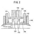
- Fig. 2 is a sectional side elevation of the lower frame.
- the lower frame 140 comprises outside lower frames 142, and inside lower frames 144 within the respective outside lower frames 142.
- the inside lower frames 144 are provided with the vacuum faces 120 for adhering material to be adhered, such as a carcass material including, for example, plies, belt, and so forth, of a tire, positioned at the lower ends of the respective inside lower frames 144, and a pin support 154 linked with the pistons 151 of each of the air cylinders 150 causes the press-down pins 152 to protrude from the vacuum face 120, as shown by broken lines in the figure, by a down-stroke of the pistons 151, to forcefully separate the material adhered at a release position as described later on.
- a carcass material including, for example, plies, belt, and so forth
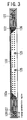
- Fig. 3 is a view showing the vacuum face 120 provided at the lower ends of the respective inside lower frames 144. There are provided a multitude of vacuum adhesion orifices 122 communicating with a vacuum duct 146 ( Fig, 2 ), open to the vacuum face 120, and a plurality of L-shaped vacuum adhesion grooves 127 for vacuum-adhering the material M ( Fig.
- the end parts of the vacuum face 120 each are provided with grooves in a shape resembling the letter L, 1 mm in depth, and 8 mm in interval, running in parallel with the direction of flow of the material adhered, and with the direction of conveyance, and the grooves are disposed in parallel with each other, and at equal intervals therebetween against respective square parts of the vacuum face 120.
- the parts of the vacuum face 120, provided with the L-shaped vacuum adhesion grooves, are installed away by an interval from the vacuum duct 146 installed in a region outside the influence of the zigzag move of the material M as adhered, and the material M yet to be adhered undergoes vacuum adhesion by the agency of vacuum in the vacuum duct 146.
- the present vacuum conveying apparatus even if the material M as adhered moves in a zigzag direction, the L-shaped vacuum adhesion grooves 127, 128, covered by the material M, implement vacuum adhesion of the material M, and portions of the parts of the vacuum face 120, provided with the L-shaped vacuum adhesion grooves, from which the material M is dislodged, will be disposed to the atmosphere, however, since the vacuum duct 146 is installed away therefrom, drop in suction pressure never occurs although, in the case of the conventional apparatus, if the material M as adhered moves in the zigzag direction to become thereby dislodged from the vacuum face, the atmosphere flows into the vacuum duct 146 through part of the vacuum face, from which the material M adhered is dislodged, thereby causing improper adhesion, and separating the tip of the material M, in the direction of conveyance, in such a way as to curl up the same.
- the vacuum face 120 is further provided with insertion hole 152a for the press-down pins 152, respectively, disposed as to be evenly distributed across the surface thereof, and the press-down pins 152 protrude from inside of the vacuum face, that is, inside of the vacuum duct 146, at the down-stroke of the pistons 151, thereby pressing down the material adhered.
- Down-timing of the press-down pins 152 is controlled so as to start upon the lower frame 140 of the vacuum conveying apparatus, reaching a down bottom dead center, and position control is made such that the forefront one of the press-down pins 152, toward the destination of conveyance, at the bottom dead center thereof, comes into contact with the upper face of a conveyer.
- the material adhered can be forcefully separated off by causing the press-down pins 152 to protrude from inside of the vacuum face, however, in order to effect more reliable release operation, Teflon (registered trademark) coating is applied to the vacuum face after knurling is applied thereto, thereby enabling delay in operation actuated by variation in press-down pressure of the press-down pins 152 to be substantially eliminated.
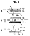
- Fig. 4A shows the vacuum conveying apparatus 100 in the standby position.
- the vacuum conveying apparatus 100 is standing by above the material M yet to be adhered and placed on a conveyer 20.
- the piston rod 112 of the air cylinders 110 is retracted in the air cylinders 110, and the lower frame 140 is in a position away from the material M yet to be adhered, that is, a position where the lower frame 140 does not interfere with the conveyer 20.
- the piston rod 112 of the air cylinders 110 is in a position halfway between a retraction position and an extended position, where the links 114a, 114b of the toggle mechanism are rocked following the down-stroke of the piston rod 112 to be thereby lined up, in other words, the lower frame 140 is at the bottom dead center of the down-stroke.
- the vacuum face 120 of the vacuum conveying apparatus 100 comes into contact with the material M yet to be adhered, standing by on the conveyer 20, whereupon the vacuum adhesion orifices 122, and the L-shaped vacuum adhesion grooves 127, 128, provided in the vacuum face, are stopped up by the material M to be adhered, so that the material M to be adhered is adhered by the agency of the suction pressure of the vacuum adhesion orifices 122, and the L-shaped vacuum adhesion grooves 127, 128.
- Fig. 4C shows a state where the piston rod 112 is extended to the maximum (at the bottom dead center).
- the vacuum face 120 with the material M adhered thereto by the toggle mechanism leaves from the conveyer 20, and the material M with one face thereof, lifted off the conveyer 20, is conveyed to a predetermined position by the vacuum conveying apparatus 100.
- Release of the material M as adhered, after conveyance thereof, is executed by retracting the piston rod 112 to the position shown in Fig. 4B . More specifically, in a state where the vacuum face 120 is kept in contact with another conveyer, vacuum break is implemented by sending break air into vacuum piping (not shown), and the vacuum duct 146, and the material M as adhered is immediately separated from the vacuum face 120 by causing the press-down pins 152 to protrude from the vacuum face 120 while concurrently jetting air from the air nozzles 125 via an air supply source (not shown), and piping 160.
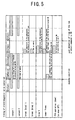
- Fig. 5 is an operation timing chart of electromagnetic valves for use in air cylinders, and so forth, used in the vacuum conveying apparatus.
- vacuum 1, and vacuum 2 refer to respective electromagnetic valves provided in vacuum pipes communicating with the vacuum duct 146, and in this case, two vacuum apparatuses are employed.
- the chart shows that with respect to respective operations of the vacuum conveying apparatus, such as adhesion, conveyance, release, and return, during the return operation after the release, that is, after 0.4 sec of a return command, a solenoid is turned ON, and the respective electromagnetic valves are actuated, thereby connecting the vacuum duct 146 to a vacuum source.
- breaks (blow) 1, 2 indicate respective electromagnetic valve operation timings to effect respective vacuum breaks corresponding to the vacuum 1, 2.
- the solenoid is turned ON for 0.1 sec upon completion of the conveyance, and the respective electromagnetic valves are opened, thereby sending air into the vacuum duct 146.
- Blow 3 indicates operation timing of an electromagnetic valve for jetting air as supplementary means at the time of separation of the material M adhered.
- a solenoid is turned ON for 0.2 sec upon completion of the conveyance, thereby jetting air onto the material M adhered.
- rise of the lower frame is effected by turning the solenoid ON for only 0.1 sec at the time of the release
- fall of the lower frame is effected by turning the solenoid ON similarly for only 0.1 sec at the time of the adhesion.
- Pin operation (down) shows that the solenoid is turned on for 0.3 sec upon the release of the material M adhered, that is, the completion of the conveyance, thereby actuating the air cylinders 150 for causing the press-down pins to come down.
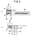
- Fig, 6 is a schematic view broadly showing operation of the high-speed vacuum conveying apparatus according to the invention
- Fig, 6A is a schematic view showing the case of moving the material M adhered in a parallel direction
- Fig, 6B is a schematic view showing the case of moving the material M adhered in an orthogonal direction.
- the vacuum conveying apparatus 100 in a position shown in Fig, 6A , lowers the vacuum face 120 of the lower frame 140 by the toggle mechanism operated by the air cylinder 110 to cause the vacuum face 120 to come into contact with the leading tip of the material M of a predetermined width, thereby adhering the material M that has been conveyed by the conveyer 20 by agency of the vacuum adhesion orifices, and subsequently, the vacuum conveying apparatus 100 in that state moves the vacuum face 120 along pull-up guides 40 to a predetermined position over another conveyer 30 orthogonal thereto.
- the vacuum conveying apparatus 100 having reached the predetermined position of the vacuum face 120 lowers the vacuum face 120 to thereby bring the material M as adhered in contact with the conveyer 30, whereupon the material M adhered is separated from the vacuum face 120 by causing the press-down pins to protrude from the vacuum face 120 and concurrently jetting air from the plurality of the air nozzles while vacuum break is concurrently carried out by sending break air into the vacuum adhesion orifices communicating with the vacuum piping, and the vacuum duct.
- the vacuum conveying apparatus 100 adheres an edge of the material M of a predetermined width, to be adhered, on the right side in the figure, and conveys the same in the direction orthogonal to the conveyer 20 to be thereby placed on another conveyer 31 or 32.
- the rise and fall of the vacuum face 120, separation of the material M, and so forth are the same as described with reference to Fig, 6A .
- the invention provides a vacuum conveying apparatus capable of rapidly executing release operation by enabling even sticky material adhered to be immediately and reliably released at a release position, and the vacuum conveying apparatus is quite useful as the same can adhere, for example, an intermediate process material for tire, particularly, sticky material such as a carcass material including plies, belt, and so forth, for high-speed conveyance, and forcefully separate the same at a predetermined position to thereby prevent adhesion.
Landscapes
- Engineering & Computer Science (AREA)
- Mechanical Engineering (AREA)
- Robotics (AREA)
- Tyre Moulding (AREA)
- Manipulator (AREA)
- Feeding Of Articles By Means Other Than Belts Or Rollers (AREA)
- Sheets, Magazines, And Separation Thereof (AREA)
- Processing And Handling Of Plastics And Other Materials For Molding In General (AREA)
Claims (8)
- Unterdruck-Fördervorrichtung (100), die einen oberen Rahmen (130), einen unteren Rahmen (140), der dazu in der Lage ist, Auf- und Abbewegungen im Verhältnis zu dem oberen Rahmen vorzunehmen, gekennzeichnet durch eine Unterdruckfläche (120), die an dem unteren Rahmen bereitgestellt wird, wobei die Unterdruckfläche mit einer Vielzahl von Unterdruck-Haftungsöffnungen (122), die in Verbindung mit einer Unterdruckleitung (146) stehen, in einem Bereich unterhalb der Unterdruckleitung, und einer Vielzahl von L-förmigen, parallel zueinander entlang einer Längsrichtung der Unterdruckfläche angeordneten, Unterdruck-Haftungsrillen (127), die in Verbindung mit der Unterdruckleitung stehen, in Bereichen an jeweiligen Enden der Unterdruckfläche, außer dem Bereich unterhalb der Unterdruckleitung, versehen ist.
- Unterdruck-Fördervorrichtung nach Anspruch 1, wobei die Unterdruck-Haftungsrillen eine Form haben, die im Wesentlichen in einer Draufsicht an den Buchstaben L erinnert.
- Unterdruck-Fördervorrichtung nach Anspruch 1 oder 2, wobei die Unterdruckfläche mit einer Vielzahl von Niederdrückstiften (152) versehen ist, die dazu in der Lage sind, von der Unterdruckfläche aus nach unten vorzuspringen, an einer Position, wo der untere Rahmen zum Zeitpunkt des Lösens der Haftung durch die Unterdruck-Fördervorrichtung nach unten kommt.
- Unterdruck-Fördervorrichtung nach Anspruch 1 oder 2, wobei eine Oberflächenbehandlung zur Verhinderung einer Haftung auf die Unterdruckfläche aufgebracht ist und die Unterdruckfläche mit einer Vielzahl von Luftdüsen (125) versehen ist, um zum Zeitpunkt des Lösens der Haftung durch die Unterdruck-Fördervorrichtung Luft auf anhaftendes Material (M) ausströmen zu lassen.
- Unterdruck-Fördervorrichtung nach Anspruch 1 oder 2, wobei der obere Rahmen und der untere Rahmen einen Kniehebel-Mechanismus darstellen, der durch jeweilige Bewegungen eines Zylinders (110) und eines Kolbens angetrieben wird, und der Kniehebelmechanismus mit Gliedern (114a, 114b) versehen ist, wobei das eine Ende jedes der Glieder koaxial und gelenkig an einer Kolbenstange (112) des Kolbens befestigt ist, während das andere Ende desselben gelenkig am dem oberen Rahmen oder dem unteren Rahmen befestigt ist.
- Unterdruck-Fördervorrichtung nach Anspruch 3, wobei eine Oberflächenbehandlung zur Verhinderung einer Haftung auf die Unterdruckfläche aufgebracht ist und die Unterdruckfläche mit einer Vielzahl von Luftdüsen (125) versehen ist, um zum Zeitpunkt des Lösens der Haftung durch die Unterdruck-Fördervorrichtung Luft auf anhaftendes Material (M) ausströmen zu lassen.
- Unterdruck-Fördervorrichtung nach Anspruch 3, wobei ein oberer Rahmen und ein unterer Rahmen einen Kniehebel-Mechanismus darstellen, der durch jeweilige Bewegungen eines Zylinders (110) und eines Kolbens angetrieben wird, und der Kniehebelmechanismus mit Gliedern (114a, 114b) versehen ist, wobei das eine Ende jedes der Glieder koaxial und gelenkig an einer Kolbenstange (112) des Kolbens befestigt ist, während das andere Ende desselben gelenkig am dem oberen Rahmen oder dem unteren Rahmen befestigt ist.
- Unterdruck-Fördervorrichtung nach Anspruch 4, wobei ein oberer Rahmen und ein unterer Rahmen einen Kniehebel-Mechanismus darstellen, der durch jeweilige Bewegungen eines Zylinders (110) und eines Kolbens angetrieben wird, und der Kniehebelmechanismus mit Gliedern (114a, 114b) versehen ist, wobei das eine Ende jedes der Glieder koaxial und gelenkig an einer Kolbenstange (112) des Kolbens befestigt ist, während das andere Ende desselben gelenkig am dem oberen Rahmen oder dem unteren Rahmen befestigt ist.
Applications Claiming Priority (3)
| Application Number | Priority Date | Filing Date | Title |
|---|---|---|---|
| JP2002338247A JP4761341B2 (ja) | 2002-11-21 | 2002-11-21 | 吸着搬送装置 |
| JP2002338247 | 2002-11-21 | ||
| PCT/JP2003/014834 WO2004045809A1 (ja) | 2002-11-21 | 2003-11-20 | 吸着搬送装置 |
Publications (3)
| Publication Number | Publication Date |
|---|---|
| EP1568448A1 EP1568448A1 (de) | 2005-08-31 |
| EP1568448A4 EP1568448A4 (de) | 2008-10-08 |
| EP1568448B1 true EP1568448B1 (de) | 2013-04-24 |
Family
ID=32321885
Family Applications (1)
| Application Number | Title | Priority Date | Filing Date |
|---|---|---|---|
| EP03774098.2A Expired - Lifetime EP1568448B1 (de) | 2002-11-21 | 2003-11-20 | Saugfördervorrichtung |
Country Status (5)
| Country | Link |
|---|---|
| US (1) | US7717482B2 (de) |
| EP (1) | EP1568448B1 (de) |
| JP (1) | JP4761341B2 (de) |
| CN (1) | CN100404213C (de) |
| WO (1) | WO2004045809A1 (de) |
Families Citing this family (29)
| Publication number | Priority date | Publication date | Assignee | Title |
|---|---|---|---|---|
| US7409812B2 (en) * | 2006-06-29 | 2008-08-12 | Smart Motion Robotics, Inc. | Robotic packaging device and method |
| TWI333248B (en) * | 2006-08-18 | 2010-11-11 | King Yuan Electronics Co Ltd | Pick-up head device with a pushing mechanism |
| CN101081510B (zh) * | 2007-06-29 | 2010-10-06 | 于复生 | 瓷砖搬运机械手装置 |
| CN101857151B (zh) * | 2009-04-10 | 2013-01-09 | 友达光电(厦门)有限公司 | 缓冲垫吸取装置及吸取方法 |
| GB0918345D0 (en) * | 2009-10-20 | 2009-12-02 | Altevo Ltd | Stacking of gloves |
| CN101948051A (zh) * | 2010-08-31 | 2011-01-19 | 佛山市南海瑞洲科技有限公司 | 一种带有吸附功能的传送工作台 |
| DE102011002614B3 (de) * | 2011-01-13 | 2012-06-06 | J. Schmalz Gmbh | Vorrichtung zum Fixieren oder Greifen von Werkstücken |
| US8755925B2 (en) | 2011-11-18 | 2014-06-17 | Nike, Inc. | Automated identification and assembly of shoe parts |
| US8858744B2 (en) | 2011-11-18 | 2014-10-14 | Nike, Inc. | Multi-functional manufacturing tool |
| US8849620B2 (en) | 2011-11-18 | 2014-09-30 | Nike, Inc. | Automated 3-D modeling of shoe parts |
| US8958901B2 (en) | 2011-11-18 | 2015-02-17 | Nike, Inc. | Automated manufacturing of shoe parts |
| US10552551B2 (en) | 2011-11-18 | 2020-02-04 | Nike, Inc. | Generation of tool paths for shore assembly |
| US8696043B2 (en) | 2011-11-18 | 2014-04-15 | Nike, Inc. | Hybrid pickup tool |
| US9010827B2 (en) | 2011-11-18 | 2015-04-21 | Nike, Inc. | Switchable plate manufacturing vacuum tool |
| US9451810B2 (en) | 2011-11-18 | 2016-09-27 | Nike, Inc. | Automated identification of shoe parts |
| US8960745B2 (en) | 2011-11-18 | 2015-02-24 | Nike, Inc | Zoned activation manufacturing vacuum tool |
| EP2952302B1 (de) * | 2014-06-05 | 2019-03-20 | J. Schmalz GmbH | Greif- oder haltevorrichtung |
| EP2952303B1 (de) | 2014-06-05 | 2017-10-11 | J. Schmalz GmbH | Verfahren zur handhabung von flexiblen mattenartigen werkstücken |
| CN104191488B (zh) * | 2014-07-28 | 2016-06-22 | 广东省宜华木业股份有限公司 | 木地板表面仿古凹槽加工用真空吸附装置及地板装夹方法 |
| WO2016204745A1 (en) * | 2015-06-17 | 2016-12-22 | Compagnie Generale Des Etablissements Michelin | A transporter for posing a tire ply on a drum and method of using the same |
| NL2018380B1 (en) * | 2017-02-15 | 2018-09-06 | Vmi Holland Bv | Transfer device and method for transferring a tire component |
| JP7011294B2 (ja) * | 2017-11-10 | 2022-01-26 | 株式会社イシダ | 物品移載装置及び物品移載方法 |
| FR3073766B1 (fr) * | 2017-11-22 | 2019-10-25 | Coval | Dispositif de prehension avec surveillance de son etat de fonctionnement |
| CN108275458B (zh) * | 2018-01-10 | 2024-03-15 | 深圳市升宇智能科技有限公司 | 一种fpc板智能吸放装置 |
| DE102018208126A1 (de) * | 2018-05-23 | 2019-11-28 | Trumpf Werkzeugmaschinen Gmbh + Co. Kg | Verfahren zum Hantieren eines Werkstücks mit Hilfe eines Entnahmewerkzeugs und Maschine zur Durchführung des Verfahrens |
| EP3578323B1 (de) * | 2018-06-05 | 2020-08-12 | C.R.F. Società Consortile per Azioni | Greifvorrichtung vom saugtyp |
| CN109822312A (zh) * | 2019-03-13 | 2019-05-31 | 上海新灏机电设备有限公司 | 一种epb电机齿轮单元电机后盖取料装置 |
| US20230278237A1 (en) * | 2020-06-26 | 2023-09-07 | Cryovac, Llc | Passive valves for vacuum manifolds |
| US20240100720A1 (en) * | 2021-09-27 | 2024-03-28 | Illinois Tool Works Inc. | Arrayed vacuum end of arm tool |
Family Cites Families (20)
| Publication number | Priority date | Publication date | Assignee | Title |
|---|---|---|---|---|
| US2853333A (en) * | 1955-09-07 | 1958-09-23 | Littell Machine Co F J | Vacuum cup |
| US3720433A (en) * | 1970-09-29 | 1973-03-13 | Us Navy | Manipulator apparatus for gripping submerged objects |
| CA1077387A (en) * | 1977-07-15 | 1980-05-13 | Stephen C. Clark | Automatic load unload turret punch |
| US4432701A (en) * | 1981-04-07 | 1984-02-21 | Yoji Ise | Vacuum controlling device |
| US4443099A (en) * | 1982-02-17 | 1984-04-17 | Lucht Engineering Corporation | Photographic printing system |
| JPS5919647A (ja) * | 1982-07-26 | 1984-02-01 | Toyoda Mach Works Ltd | 真空チヤツク |
| JPS60127935A (ja) * | 1983-12-14 | 1985-07-08 | Fujitsu Ltd | ウエハ−チヤツク |
| US5048811A (en) * | 1989-07-31 | 1991-09-17 | Aluminum Company Of America | Single head device for removing alternate articles from a stack of the articles |
| JPH03200639A (ja) * | 1989-12-28 | 1991-09-02 | Minolta Camera Co Ltd | シート給送装置 |
| US5305809A (en) * | 1992-10-20 | 1994-04-26 | R & D Innovators, Inc. | Gang array filler with relocatable nozzles |
| EP0659666B1 (de) * | 1993-12-21 | 1998-12-02 | Central Glass Company, Limited | Verfahren und Vorrichtung zur Handhabung von Folien |
| JPH1086085A (ja) * | 1996-09-19 | 1998-04-07 | Dainippon Screen Mfg Co Ltd | 基板吸着装置および基板吸着方法 |
| JP3673604B2 (ja) * | 1996-10-31 | 2005-07-20 | キヤノン株式会社 | シート供給装置及び該装置を用いた記録読取装置 |
| JPH10180677A (ja) * | 1996-12-20 | 1998-07-07 | Amada Eng Center:Kk | 原点位置決め装置 |
| JPH10180667A (ja) | 1996-12-26 | 1998-07-07 | Nkk Corp | 廃棄物中の特定物を選別するロボットシステム |
| JP2000286543A (ja) * | 1999-03-30 | 2000-10-13 | Nec Eng Ltd | はんだボール搭載方法およびこれを利用するはんだボール搭載装置 |
| JP4109383B2 (ja) * | 1999-05-20 | 2008-07-02 | 住友ゴム工業株式会社 | 吸引吸着パッド及びそれを用いたタイヤコンポーネントの取扱い装置 |
| US6398208B1 (en) * | 2000-06-12 | 2002-06-04 | Xerox Corporation | Sheet feeding apparatus having an air plenum with a leaky seal |
| JP2002043353A (ja) * | 2000-07-28 | 2002-02-08 | Tesetsuku:Kk | Bga素子用吸着器具及び吸着方法 |
| JP4547649B2 (ja) * | 2000-07-31 | 2010-09-22 | Smc株式会社 | 吸着用パッド |
-
2002
- 2002-11-21 JP JP2002338247A patent/JP4761341B2/ja not_active Expired - Fee Related
-
2003
- 2003-11-20 US US10/535,845 patent/US7717482B2/en not_active Expired - Fee Related
- 2003-11-20 EP EP03774098.2A patent/EP1568448B1/de not_active Expired - Lifetime
- 2003-11-20 CN CNB2003801038538A patent/CN100404213C/zh not_active Expired - Fee Related
- 2003-11-20 WO PCT/JP2003/014834 patent/WO2004045809A1/ja not_active Ceased
Also Published As
| Publication number | Publication date |
|---|---|
| CN1713969A (zh) | 2005-12-28 |
| WO2004045809A1 (ja) | 2004-06-03 |
| EP1568448A4 (de) | 2008-10-08 |
| EP1568448A1 (de) | 2005-08-31 |
| JP2004167939A (ja) | 2004-06-17 |
| CN100404213C (zh) | 2008-07-23 |
| JP4761341B2 (ja) | 2011-08-31 |
| US7717482B2 (en) | 2010-05-18 |
| US20060055190A1 (en) | 2006-03-16 |
Similar Documents
| Publication | Publication Date | Title |
|---|---|---|
| US7717482B2 (en) | Suckingly conveying apparatus | |
| US4591044A (en) | Apparatus for feeding wafers and the like | |
| JP6189428B2 (ja) | 積み重ねられた被加工物の一番上から略平らな被加工物を取り出す方法及び装置 | |
| US6966742B2 (en) | Work arrangement apparatus | |
| KR100770411B1 (ko) | 커버레이 부착 시스템 및 그 방법 | |
| WO1986006356A1 (en) | A device in a machine handling package units | |
| KR20190078798A (ko) | 간지 공급 시스템 | |
| CN111284796A (zh) | 一种标识吸取及预装装置 | |
| EP2530037B1 (de) | Verfahren und System zur Verarbeitung einer Lage von Produkten von einer Palette | |
| US5460480A (en) | Installation for handling the conveyance of blanks from a cutting machine to a stacking device | |
| JP5545882B2 (ja) | テープ貼付装置 | |
| US4902375A (en) | Apparatus for assembling a continuous stream of composite labels | |
| KR102062853B1 (ko) | 라벨자동부착장치 | |
| US3345922A (en) | Method and apparatus for wrapping containers | |
| TW202004979A (zh) | 黏著帶剝離方法及黏著帶剝離裝置 | |
| WO2018070299A1 (ja) | 帯状部材の切断方法および切断装置 | |
| JPH0983190A (ja) | プリント基板の汎用投入機 | |
| US12251822B2 (en) | Method for controlling a gripper | |
| JP2004315232A (ja) | 枚葉紙を処理する機械に枚葉紙を案内するための方法および装置 | |
| US6899512B2 (en) | Bottom sheet inserter | |
| JP2000176889A (ja) | 電子部品の切断搬送装置 | |
| KR100727689B1 (ko) | 판재 투입기, 판재 적재기 및 이들의 제어방법 | |
| KR200373622Y1 (ko) | 판지공급기의 위치결정장치 | |
| JP2020019623A (ja) | 給紙方法および給紙装置 | |
| JP2001310282A (ja) | 搬送装置の制御方法 |
Legal Events
| Date | Code | Title | Description |
|---|---|---|---|
| PUAI | Public reference made under article 153(3) epc to a published international application that has entered the european phase |
Free format text: ORIGINAL CODE: 0009012 |
|
| 17P | Request for examination filed |
Effective date: 20050504 |
|
| AK | Designated contracting states |
Kind code of ref document: A1 Designated state(s): DE ES FR GB IT |
|
| A4 | Supplementary search report drawn up and despatched |
Effective date: 20080904 |
|
| RIC1 | Information provided on ipc code assigned before grant |
Ipc: B25J 15/06 20060101AFI20040609BHEP Ipc: B25B 11/00 20060101ALI20080829BHEP |
|
| 17Q | First examination report despatched |
Effective date: 20100728 |
|
| GRAP | Despatch of communication of intention to grant a patent |
Free format text: ORIGINAL CODE: EPIDOSNIGR1 |
|
| GRAS | Grant fee paid |
Free format text: ORIGINAL CODE: EPIDOSNIGR3 |
|
| GRAA | (expected) grant |
Free format text: ORIGINAL CODE: 0009210 |
|
| AK | Designated contracting states |
Kind code of ref document: B1 Designated state(s): DE ES FR GB IT |
|
| REG | Reference to a national code |
Ref country code: GB Ref legal event code: FG4D |
|
| REG | Reference to a national code |
Ref country code: DE Ref legal event code: R096 Ref document number: 60343896 Country of ref document: DE Effective date: 20130627 |
|
| PG25 | Lapsed in a contracting state [announced via postgrant information from national office to epo] |
Ref country code: ES Free format text: LAPSE BECAUSE OF FAILURE TO SUBMIT A TRANSLATION OF THE DESCRIPTION OR TO PAY THE FEE WITHIN THE PRESCRIBED TIME-LIMIT Effective date: 20130804 |
|
| PLBE | No opposition filed within time limit |
Free format text: ORIGINAL CODE: 0009261 |
|
| STAA | Information on the status of an ep patent application or granted ep patent |
Free format text: STATUS: NO OPPOSITION FILED WITHIN TIME LIMIT |
|
| 26N | No opposition filed |
Effective date: 20140127 |
|
| REG | Reference to a national code |
Ref country code: DE Ref legal event code: R097 Ref document number: 60343896 Country of ref document: DE Effective date: 20140127 |
|
| GBPC | Gb: european patent ceased through non-payment of renewal fee |
Effective date: 20131120 |
|
| REG | Reference to a national code |
Ref country code: FR Ref legal event code: CA Effective date: 20140812 |
|
| PG25 | Lapsed in a contracting state [announced via postgrant information from national office to epo] |
Ref country code: GB Free format text: LAPSE BECAUSE OF NON-PAYMENT OF DUE FEES Effective date: 20131120 |
|
| REG | Reference to a national code |
Ref country code: FR Ref legal event code: PLFP Year of fee payment: 13 |
|
| REG | Reference to a national code |
Ref country code: FR Ref legal event code: PLFP Year of fee payment: 14 |
|
| REG | Reference to a national code |
Ref country code: FR Ref legal event code: PLFP Year of fee payment: 15 |
|
| PGFP | Annual fee paid to national office [announced via postgrant information from national office to epo] |
Ref country code: DE Payment date: 20191121 Year of fee payment: 17 |
|
| PGFP | Annual fee paid to national office [announced via postgrant information from national office to epo] |
Ref country code: IT Payment date: 20191128 Year of fee payment: 17 Ref country code: FR Payment date: 20191120 Year of fee payment: 17 |
|
| REG | Reference to a national code |
Ref country code: DE Ref legal event code: R119 Ref document number: 60343896 Country of ref document: DE |
|
| PG25 | Lapsed in a contracting state [announced via postgrant information from national office to epo] |
Ref country code: IT Free format text: LAPSE BECAUSE OF NON-PAYMENT OF DUE FEES Effective date: 20201120 Ref country code: FR Free format text: LAPSE BECAUSE OF NON-PAYMENT OF DUE FEES Effective date: 20201130 |
|
| PG25 | Lapsed in a contracting state [announced via postgrant information from national office to epo] |
Ref country code: DE Free format text: LAPSE BECAUSE OF NON-PAYMENT OF DUE FEES Effective date: 20210601 |