EP1568412A1 - Chemischer Reaktor und Verfahren zur katalytischen Gasphasenreaktionen - Google Patents
Chemischer Reaktor und Verfahren zur katalytischen Gasphasenreaktionen Download PDFInfo
- Publication number
- EP1568412A1 EP1568412A1 EP05007860A EP05007860A EP1568412A1 EP 1568412 A1 EP1568412 A1 EP 1568412A1 EP 05007860 A EP05007860 A EP 05007860A EP 05007860 A EP05007860 A EP 05007860A EP 1568412 A1 EP1568412 A1 EP 1568412A1
- Authority
- EP
- European Patent Office
- Prior art keywords
- reaction chamber
- chamber
- porous
- catalyst
- less
- Prior art date
- Legal status (The legal status is an assumption and is not a legal conclusion. Google has not performed a legal analysis and makes no representation as to the accuracy of the status listed.)
- Granted
Links
Images






Classifications
-
- C—CHEMISTRY; METALLURGY
- C01—INORGANIC CHEMISTRY
- C01B—NON-METALLIC ELEMENTS; COMPOUNDS THEREOF; METALLOIDS OR COMPOUNDS THEREOF NOT COVERED BY SUBCLASS C01C
- C01B3/00—Hydrogen; Gaseous mixtures containing hydrogen; Separation of hydrogen from mixtures containing it; Purification of hydrogen; Reversible storage of hydrogen
- C01B3/02—Production of hydrogen; Production of gaseous mixtures containing hydrogen
- C01B3/32—Production of hydrogen; Production of gaseous mixtures containing hydrogen by reaction of gaseous or liquid organic compounds with gasifying agents, e.g. water, carbon dioxide or air
- C01B3/34—Production of hydrogen; Production of gaseous mixtures containing hydrogen by reaction of gaseous or liquid organic compounds with gasifying agents, e.g. water, carbon dioxide or air by reaction of hydrocarbons with gasifying agents
- C01B3/38—Production of hydrogen; Production of gaseous mixtures containing hydrogen by reaction of gaseous or liquid organic compounds with gasifying agents, e.g. water, carbon dioxide or air by reaction of hydrocarbons with gasifying agents using catalysts
- C01B3/384—Production of hydrogen; Production of gaseous mixtures containing hydrogen by reaction of gaseous or liquid organic compounds with gasifying agents, e.g. water, carbon dioxide or air by reaction of hydrocarbons with gasifying agents using catalysts with external heating of the catalyst
-
- B—PERFORMING OPERATIONS; TRANSPORTING
- B01—PHYSICAL OR CHEMICAL PROCESSES OR APPARATUS IN GENERAL
- B01J—CHEMICAL OR PHYSICAL PROCESSES, e.g. CATALYSIS OR COLLOID CHEMISTRY; THEIR RELEVANT APPARATUS
- B01J12/00—Chemical processes in general for reacting gaseous media with gaseous media; Apparatus specially adapted therefor
- B01J12/007—Chemical processes in general for reacting gaseous media with gaseous media; Apparatus specially adapted therefor in the presence of catalytically active bodies, e.g. porous plates
-
- B—PERFORMING OPERATIONS; TRANSPORTING
- B01—PHYSICAL OR CHEMICAL PROCESSES OR APPARATUS IN GENERAL
- B01J—CHEMICAL OR PHYSICAL PROCESSES, e.g. CATALYSIS OR COLLOID CHEMISTRY; THEIR RELEVANT APPARATUS
- B01J19/00—Chemical, physical or physico-chemical processes in general; Their relevant apparatus
- B01J19/0093—Microreactors, e.g. miniaturised or microfabricated reactors
-
- B—PERFORMING OPERATIONS; TRANSPORTING
- B01—PHYSICAL OR CHEMICAL PROCESSES OR APPARATUS IN GENERAL
- B01J—CHEMICAL OR PHYSICAL PROCESSES, e.g. CATALYSIS OR COLLOID CHEMISTRY; THEIR RELEVANT APPARATUS
- B01J23/00—Catalysts comprising metals or metal oxides or hydroxides, not provided for in group B01J21/00
- B01J23/38—Catalysts comprising metals or metal oxides or hydroxides, not provided for in group B01J21/00 of noble metals
- B01J23/54—Catalysts comprising metals or metal oxides or hydroxides, not provided for in group B01J21/00 of noble metals combined with metals, oxides or hydroxides provided for in groups B01J23/02 - B01J23/36
- B01J23/56—Platinum group metals
- B01J23/60—Platinum group metals with zinc, cadmium or mercury
-
- B—PERFORMING OPERATIONS; TRANSPORTING
- B01—PHYSICAL OR CHEMICAL PROCESSES OR APPARATUS IN GENERAL
- B01J—CHEMICAL OR PHYSICAL PROCESSES, e.g. CATALYSIS OR COLLOID CHEMISTRY; THEIR RELEVANT APPARATUS
- B01J37/00—Processes, in general, for preparing catalysts; Processes, in general, for activation of catalysts
- B01J37/02—Impregnation, coating or precipitation
- B01J37/0215—Coating
-
- C—CHEMISTRY; METALLURGY
- C01—INORGANIC CHEMISTRY
- C01B—NON-METALLIC ELEMENTS; COMPOUNDS THEREOF; METALLOIDS OR COMPOUNDS THEREOF NOT COVERED BY SUBCLASS C01C
- C01B13/00—Oxygen; Ozone; Oxides or hydroxides in general
- C01B13/02—Preparation of oxygen
- C01B13/0229—Purification or separation processes
- C01B13/0248—Physical processing only
- C01B13/0251—Physical processing only by making use of membranes
-
- C—CHEMISTRY; METALLURGY
- C01—INORGANIC CHEMISTRY
- C01B—NON-METALLIC ELEMENTS; COMPOUNDS THEREOF; METALLOIDS OR COMPOUNDS THEREOF NOT COVERED BY SUBCLASS C01C
- C01B3/00—Hydrogen; Gaseous mixtures containing hydrogen; Separation of hydrogen from mixtures containing it; Purification of hydrogen; Reversible storage of hydrogen
- C01B3/02—Production of hydrogen; Production of gaseous mixtures containing hydrogen
- C01B3/32—Production of hydrogen; Production of gaseous mixtures containing hydrogen by reaction of gaseous or liquid organic compounds with gasifying agents, e.g. water, carbon dioxide or air
- C01B3/34—Production of hydrogen; Production of gaseous mixtures containing hydrogen by reaction of gaseous or liquid organic compounds with gasifying agents, e.g. water, carbon dioxide or air by reaction of hydrocarbons with gasifying agents
- C01B3/38—Production of hydrogen; Production of gaseous mixtures containing hydrogen by reaction of gaseous or liquid organic compounds with gasifying agents, e.g. water, carbon dioxide or air by reaction of hydrocarbons with gasifying agents using catalysts
-
- C—CHEMISTRY; METALLURGY
- C01—INORGANIC CHEMISTRY
- C01B—NON-METALLIC ELEMENTS; COMPOUNDS THEREOF; METALLOIDS OR COMPOUNDS THEREOF NOT COVERED BY SUBCLASS C01C
- C01B3/00—Hydrogen; Gaseous mixtures containing hydrogen; Separation of hydrogen from mixtures containing it; Purification of hydrogen; Reversible storage of hydrogen
- C01B3/50—Separation of hydrogen or hydrogen-containing gases from gaseous mixtures, e.g. purification
- C01B3/501—Separation of hydrogen or hydrogen-containing gases from gaseous mixtures, e.g. purification by diffusion
-
- H—ELECTRICITY
- H01—ELECTRIC ELEMENTS
- H01M—PROCESSES OR MEANS, e.g. BATTERIES, FOR THE DIRECT CONVERSION OF CHEMICAL ENERGY INTO ELECTRICAL ENERGY
- H01M8/00—Fuel cells; Manufacture thereof
- H01M8/06—Combination of fuel cells with means for production of reactants or for treatment of residues
- H01M8/0606—Combination of fuel cells with means for production of reactants or for treatment of residues with means for production of gaseous reactants
- H01M8/0612—Combination of fuel cells with means for production of reactants or for treatment of residues with means for production of gaseous reactants from carbon-containing material
-
- B—PERFORMING OPERATIONS; TRANSPORTING
- B01—PHYSICAL OR CHEMICAL PROCESSES OR APPARATUS IN GENERAL
- B01J—CHEMICAL OR PHYSICAL PROCESSES, e.g. CATALYSIS OR COLLOID CHEMISTRY; THEIR RELEVANT APPARATUS
- B01J2219/00—Chemical, physical or physico-chemical processes in general; Their relevant apparatus
- B01J2219/00049—Controlling or regulating processes
- B01J2219/00051—Controlling the temperature
- B01J2219/00159—Controlling the temperature controlling multiple zones along the direction of flow, e.g. pre-heating and after-cooling
-
- B—PERFORMING OPERATIONS; TRANSPORTING
- B01—PHYSICAL OR CHEMICAL PROCESSES OR APPARATUS IN GENERAL
- B01J—CHEMICAL OR PHYSICAL PROCESSES, e.g. CATALYSIS OR COLLOID CHEMISTRY; THEIR RELEVANT APPARATUS
- B01J2219/00—Chemical, physical or physico-chemical processes in general; Their relevant apparatus
- B01J2219/00781—Aspects relating to microreactors
- B01J2219/00783—Laminate assemblies, i.e. the reactor comprising a stack of plates
-
- B—PERFORMING OPERATIONS; TRANSPORTING
- B01—PHYSICAL OR CHEMICAL PROCESSES OR APPARATUS IN GENERAL
- B01J—CHEMICAL OR PHYSICAL PROCESSES, e.g. CATALYSIS OR COLLOID CHEMISTRY; THEIR RELEVANT APPARATUS
- B01J2219/00—Chemical, physical or physico-chemical processes in general; Their relevant apparatus
- B01J2219/00781—Aspects relating to microreactors
- B01J2219/00819—Materials of construction
- B01J2219/00822—Metal
-
- B—PERFORMING OPERATIONS; TRANSPORTING
- B01—PHYSICAL OR CHEMICAL PROCESSES OR APPARATUS IN GENERAL
- B01J—CHEMICAL OR PHYSICAL PROCESSES, e.g. CATALYSIS OR COLLOID CHEMISTRY; THEIR RELEVANT APPARATUS
- B01J2219/00—Chemical, physical or physico-chemical processes in general; Their relevant apparatus
- B01J2219/00781—Aspects relating to microreactors
- B01J2219/00819—Materials of construction
- B01J2219/00824—Ceramic
-
- B—PERFORMING OPERATIONS; TRANSPORTING
- B01—PHYSICAL OR CHEMICAL PROCESSES OR APPARATUS IN GENERAL
- B01J—CHEMICAL OR PHYSICAL PROCESSES, e.g. CATALYSIS OR COLLOID CHEMISTRY; THEIR RELEVANT APPARATUS
- B01J2219/00—Chemical, physical or physico-chemical processes in general; Their relevant apparatus
- B01J2219/00781—Aspects relating to microreactors
- B01J2219/00819—Materials of construction
- B01J2219/00835—Comprising catalytically active material
-
- B—PERFORMING OPERATIONS; TRANSPORTING
- B01—PHYSICAL OR CHEMICAL PROCESSES OR APPARATUS IN GENERAL
- B01J—CHEMICAL OR PHYSICAL PROCESSES, e.g. CATALYSIS OR COLLOID CHEMISTRY; THEIR RELEVANT APPARATUS
- B01J2219/00—Chemical, physical or physico-chemical processes in general; Their relevant apparatus
- B01J2219/00781—Aspects relating to microreactors
- B01J2219/00819—Materials of construction
- B01J2219/00844—Comprising porous material
-
- B—PERFORMING OPERATIONS; TRANSPORTING
- B01—PHYSICAL OR CHEMICAL PROCESSES OR APPARATUS IN GENERAL
- B01J—CHEMICAL OR PHYSICAL PROCESSES, e.g. CATALYSIS OR COLLOID CHEMISTRY; THEIR RELEVANT APPARATUS
- B01J2219/00—Chemical, physical or physico-chemical processes in general; Their relevant apparatus
- B01J2219/00781—Aspects relating to microreactors
- B01J2219/00873—Heat exchange
-
- B—PERFORMING OPERATIONS; TRANSPORTING
- B01—PHYSICAL OR CHEMICAL PROCESSES OR APPARATUS IN GENERAL
- B01J—CHEMICAL OR PHYSICAL PROCESSES, e.g. CATALYSIS OR COLLOID CHEMISTRY; THEIR RELEVANT APPARATUS
- B01J2219/00—Chemical, physical or physico-chemical processes in general; Their relevant apparatus
- B01J2219/00781—Aspects relating to microreactors
- B01J2219/00905—Separation
- B01J2219/00907—Separation using membranes
-
- B—PERFORMING OPERATIONS; TRANSPORTING
- B01—PHYSICAL OR CHEMICAL PROCESSES OR APPARATUS IN GENERAL
- B01J—CHEMICAL OR PHYSICAL PROCESSES, e.g. CATALYSIS OR COLLOID CHEMISTRY; THEIR RELEVANT APPARATUS
- B01J2219/00—Chemical, physical or physico-chemical processes in general; Their relevant apparatus
- B01J2219/00781—Aspects relating to microreactors
- B01J2219/0095—Control aspects
- B01J2219/00984—Residence time
-
- B—PERFORMING OPERATIONS; TRANSPORTING
- B01—PHYSICAL OR CHEMICAL PROCESSES OR APPARATUS IN GENERAL
- B01J—CHEMICAL OR PHYSICAL PROCESSES, e.g. CATALYSIS OR COLLOID CHEMISTRY; THEIR RELEVANT APPARATUS
- B01J2219/00—Chemical, physical or physico-chemical processes in general; Their relevant apparatus
- B01J2219/24—Stationary reactors without moving elements inside
- B01J2219/2401—Reactors comprising multiple separate flow channels
- B01J2219/245—Plate-type reactors
- B01J2219/2451—Geometry of the reactor
- B01J2219/2453—Plates arranged in parallel
-
- B—PERFORMING OPERATIONS; TRANSPORTING
- B01—PHYSICAL OR CHEMICAL PROCESSES OR APPARATUS IN GENERAL
- B01J—CHEMICAL OR PHYSICAL PROCESSES, e.g. CATALYSIS OR COLLOID CHEMISTRY; THEIR RELEVANT APPARATUS
- B01J2219/00—Chemical, physical or physico-chemical processes in general; Their relevant apparatus
- B01J2219/24—Stationary reactors without moving elements inside
- B01J2219/2401—Reactors comprising multiple separate flow channels
- B01J2219/245—Plate-type reactors
- B01J2219/2461—Heat exchange aspects
- B01J2219/2465—Two reactions in indirect heat exchange with each other
-
- B—PERFORMING OPERATIONS; TRANSPORTING
- B01—PHYSICAL OR CHEMICAL PROCESSES OR APPARATUS IN GENERAL
- B01J—CHEMICAL OR PHYSICAL PROCESSES, e.g. CATALYSIS OR COLLOID CHEMISTRY; THEIR RELEVANT APPARATUS
- B01J2219/00—Chemical, physical or physico-chemical processes in general; Their relevant apparatus
- B01J2219/24—Stationary reactors without moving elements inside
- B01J2219/2401—Reactors comprising multiple separate flow channels
- B01J2219/245—Plate-type reactors
- B01J2219/2474—Mixing means, e.g. fins or baffles attached to the plates
-
- B—PERFORMING OPERATIONS; TRANSPORTING
- B01—PHYSICAL OR CHEMICAL PROCESSES OR APPARATUS IN GENERAL
- B01J—CHEMICAL OR PHYSICAL PROCESSES, e.g. CATALYSIS OR COLLOID CHEMISTRY; THEIR RELEVANT APPARATUS
- B01J2219/00—Chemical, physical or physico-chemical processes in general; Their relevant apparatus
- B01J2219/24—Stationary reactors without moving elements inside
- B01J2219/2401—Reactors comprising multiple separate flow channels
- B01J2219/245—Plate-type reactors
- B01J2219/2475—Separation means, e.g. membranes inside the reactor
-
- B—PERFORMING OPERATIONS; TRANSPORTING
- B01—PHYSICAL OR CHEMICAL PROCESSES OR APPARATUS IN GENERAL
- B01J—CHEMICAL OR PHYSICAL PROCESSES, e.g. CATALYSIS OR COLLOID CHEMISTRY; THEIR RELEVANT APPARATUS
- B01J2219/00—Chemical, physical or physico-chemical processes in general; Their relevant apparatus
- B01J2219/24—Stationary reactors without moving elements inside
- B01J2219/2401—Reactors comprising multiple separate flow channels
- B01J2219/245—Plate-type reactors
- B01J2219/2476—Construction materials
- B01J2219/2477—Construction materials of the catalysts
- B01J2219/2479—Catalysts coated on the surface of plates or inserts
-
- B—PERFORMING OPERATIONS; TRANSPORTING
- B01—PHYSICAL OR CHEMICAL PROCESSES OR APPARATUS IN GENERAL
- B01J—CHEMICAL OR PHYSICAL PROCESSES, e.g. CATALYSIS OR COLLOID CHEMISTRY; THEIR RELEVANT APPARATUS
- B01J2219/00—Chemical, physical or physico-chemical processes in general; Their relevant apparatus
- B01J2219/24—Stationary reactors without moving elements inside
- B01J2219/2401—Reactors comprising multiple separate flow channels
- B01J2219/245—Plate-type reactors
- B01J2219/2476—Construction materials
- B01J2219/2477—Construction materials of the catalysts
- B01J2219/2482—Catalytically active foils; Plates having catalytically activity on their own
-
- B—PERFORMING OPERATIONS; TRANSPORTING
- B01—PHYSICAL OR CHEMICAL PROCESSES OR APPARATUS IN GENERAL
- B01J—CHEMICAL OR PHYSICAL PROCESSES, e.g. CATALYSIS OR COLLOID CHEMISTRY; THEIR RELEVANT APPARATUS
- B01J2219/00—Chemical, physical or physico-chemical processes in general; Their relevant apparatus
- B01J2219/24—Stationary reactors without moving elements inside
- B01J2219/2401—Reactors comprising multiple separate flow channels
- B01J2219/245—Plate-type reactors
- B01J2219/2491—Other constructional details
- B01J2219/2497—Size aspects, i.e. concrete sizes are being mentioned in the classified document
-
- B—PERFORMING OPERATIONS; TRANSPORTING
- B01—PHYSICAL OR CHEMICAL PROCESSES OR APPARATUS IN GENERAL
- B01J—CHEMICAL OR PHYSICAL PROCESSES, e.g. CATALYSIS OR COLLOID CHEMISTRY; THEIR RELEVANT APPARATUS
- B01J23/00—Catalysts comprising metals or metal oxides or hydroxides, not provided for in group B01J21/00
- B01J23/38—Catalysts comprising metals or metal oxides or hydroxides, not provided for in group B01J21/00 of noble metals
- B01J23/54—Catalysts comprising metals or metal oxides or hydroxides, not provided for in group B01J21/00 of noble metals combined with metals, oxides or hydroxides provided for in groups B01J23/02 - B01J23/36
- B01J23/56—Platinum group metals
- B01J23/58—Platinum group metals with alkali- or alkaline earth metals
-
- B—PERFORMING OPERATIONS; TRANSPORTING
- B01—PHYSICAL OR CHEMICAL PROCESSES OR APPARATUS IN GENERAL
- B01J—CHEMICAL OR PHYSICAL PROCESSES, e.g. CATALYSIS OR COLLOID CHEMISTRY; THEIR RELEVANT APPARATUS
- B01J35/00—Catalysts, in general, characterised by their form or physical properties
- B01J35/50—Catalysts, in general, characterised by their form or physical properties characterised by their shape or configuration
- B01J35/56—Foraminous structures having flow-through passages or channels, e.g. grids or three-dimensional [3D] monoliths
-
- B—PERFORMING OPERATIONS; TRANSPORTING
- B01—PHYSICAL OR CHEMICAL PROCESSES OR APPARATUS IN GENERAL
- B01J—CHEMICAL OR PHYSICAL PROCESSES, e.g. CATALYSIS OR COLLOID CHEMISTRY; THEIR RELEVANT APPARATUS
- B01J37/00—Processes, in general, for preparing catalysts; Processes, in general, for activation of catalysts
- B01J37/02—Impregnation, coating or precipitation
- B01J37/03—Precipitation; Co-precipitation
- B01J37/031—Precipitation
-
- C—CHEMISTRY; METALLURGY
- C01—INORGANIC CHEMISTRY
- C01B—NON-METALLIC ELEMENTS; COMPOUNDS THEREOF; METALLOIDS OR COMPOUNDS THEREOF NOT COVERED BY SUBCLASS C01C
- C01B2203/00—Integrated processes for the production of hydrogen or synthesis gas
- C01B2203/02—Processes for making hydrogen or synthesis gas
- C01B2203/0205—Processes for making hydrogen or synthesis gas containing a reforming step
- C01B2203/0227—Processes for making hydrogen or synthesis gas containing a reforming step containing a catalytic reforming step
- C01B2203/0233—Processes for making hydrogen or synthesis gas containing a reforming step containing a catalytic reforming step the reforming step being a steam reforming step
-
- C—CHEMISTRY; METALLURGY
- C01—INORGANIC CHEMISTRY
- C01B—NON-METALLIC ELEMENTS; COMPOUNDS THEREOF; METALLOIDS OR COMPOUNDS THEREOF NOT COVERED BY SUBCLASS C01C
- C01B2203/00—Integrated processes for the production of hydrogen or synthesis gas
- C01B2203/02—Processes for making hydrogen or synthesis gas
- C01B2203/0283—Processes for making hydrogen or synthesis gas containing a CO-shift step, i.e. a water gas shift step
-
- C—CHEMISTRY; METALLURGY
- C01—INORGANIC CHEMISTRY
- C01B—NON-METALLIC ELEMENTS; COMPOUNDS THEREOF; METALLOIDS OR COMPOUNDS THEREOF NOT COVERED BY SUBCLASS C01C
- C01B2203/00—Integrated processes for the production of hydrogen or synthesis gas
- C01B2203/04—Integrated processes for the production of hydrogen or synthesis gas containing a purification step for the hydrogen or the synthesis gas
- C01B2203/0405—Purification by membrane separation
-
- C—CHEMISTRY; METALLURGY
- C01—INORGANIC CHEMISTRY
- C01B—NON-METALLIC ELEMENTS; COMPOUNDS THEREOF; METALLOIDS OR COMPOUNDS THEREOF NOT COVERED BY SUBCLASS C01C
- C01B2203/00—Integrated processes for the production of hydrogen or synthesis gas
- C01B2203/04—Integrated processes for the production of hydrogen or synthesis gas containing a purification step for the hydrogen or the synthesis gas
- C01B2203/0405—Purification by membrane separation
- C01B2203/041—In-situ membrane purification during hydrogen production
-
- C—CHEMISTRY; METALLURGY
- C01—INORGANIC CHEMISTRY
- C01B—NON-METALLIC ELEMENTS; COMPOUNDS THEREOF; METALLOIDS OR COMPOUNDS THEREOF NOT COVERED BY SUBCLASS C01C
- C01B2203/00—Integrated processes for the production of hydrogen or synthesis gas
- C01B2203/04—Integrated processes for the production of hydrogen or synthesis gas containing a purification step for the hydrogen or the synthesis gas
- C01B2203/0435—Catalytic purification
- C01B2203/044—Selective oxidation of carbon monoxide
-
- C—CHEMISTRY; METALLURGY
- C01—INORGANIC CHEMISTRY
- C01B—NON-METALLIC ELEMENTS; COMPOUNDS THEREOF; METALLOIDS OR COMPOUNDS THEREOF NOT COVERED BY SUBCLASS C01C
- C01B2203/00—Integrated processes for the production of hydrogen or synthesis gas
- C01B2203/04—Integrated processes for the production of hydrogen or synthesis gas containing a purification step for the hydrogen or the synthesis gas
- C01B2203/0465—Composition of the impurity
- C01B2203/047—Composition of the impurity the impurity being carbon monoxide
-
- C—CHEMISTRY; METALLURGY
- C01—INORGANIC CHEMISTRY
- C01B—NON-METALLIC ELEMENTS; COMPOUNDS THEREOF; METALLOIDS OR COMPOUNDS THEREOF NOT COVERED BY SUBCLASS C01C
- C01B2203/00—Integrated processes for the production of hydrogen or synthesis gas
- C01B2203/06—Integration with other chemical processes
- C01B2203/063—Refinery processes
- C01B2203/065—Refinery processes using hydrotreating, e.g. hydrogenation, hydrodesulfurisation
-
- C—CHEMISTRY; METALLURGY
- C01—INORGANIC CHEMISTRY
- C01B—NON-METALLIC ELEMENTS; COMPOUNDS THEREOF; METALLOIDS OR COMPOUNDS THEREOF NOT COVERED BY SUBCLASS C01C
- C01B2203/00—Integrated processes for the production of hydrogen or synthesis gas
- C01B2203/06—Integration with other chemical processes
- C01B2203/066—Integration with other chemical processes with fuel cells
-
- C—CHEMISTRY; METALLURGY
- C01—INORGANIC CHEMISTRY
- C01B—NON-METALLIC ELEMENTS; COMPOUNDS THEREOF; METALLOIDS OR COMPOUNDS THEREOF NOT COVERED BY SUBCLASS C01C
- C01B2203/00—Integrated processes for the production of hydrogen or synthesis gas
- C01B2203/08—Methods of heating or cooling
- C01B2203/0805—Methods of heating the process for making hydrogen or synthesis gas
- C01B2203/0811—Methods of heating the process for making hydrogen or synthesis gas by combustion of fuel
-
- C—CHEMISTRY; METALLURGY
- C01—INORGANIC CHEMISTRY
- C01B—NON-METALLIC ELEMENTS; COMPOUNDS THEREOF; METALLOIDS OR COMPOUNDS THEREOF NOT COVERED BY SUBCLASS C01C
- C01B2203/00—Integrated processes for the production of hydrogen or synthesis gas
- C01B2203/08—Methods of heating or cooling
- C01B2203/0805—Methods of heating the process for making hydrogen or synthesis gas
- C01B2203/0811—Methods of heating the process for making hydrogen or synthesis gas by combustion of fuel
- C01B2203/0822—Methods of heating the process for making hydrogen or synthesis gas by combustion of fuel the fuel containing hydrogen
-
- C—CHEMISTRY; METALLURGY
- C01—INORGANIC CHEMISTRY
- C01B—NON-METALLIC ELEMENTS; COMPOUNDS THEREOF; METALLOIDS OR COMPOUNDS THEREOF NOT COVERED BY SUBCLASS C01C
- C01B2203/00—Integrated processes for the production of hydrogen or synthesis gas
- C01B2203/08—Methods of heating or cooling
- C01B2203/0805—Methods of heating the process for making hydrogen or synthesis gas
- C01B2203/0833—Heating by indirect heat exchange with hot fluids, other than combustion gases, product gases or non-combustive exothermic reaction product gases
-
- C—CHEMISTRY; METALLURGY
- C01—INORGANIC CHEMISTRY
- C01B—NON-METALLIC ELEMENTS; COMPOUNDS THEREOF; METALLOIDS OR COMPOUNDS THEREOF NOT COVERED BY SUBCLASS C01C
- C01B2203/00—Integrated processes for the production of hydrogen or synthesis gas
- C01B2203/08—Methods of heating or cooling
- C01B2203/0805—Methods of heating the process for making hydrogen or synthesis gas
- C01B2203/0838—Methods of heating the process for making hydrogen or synthesis gas by heat exchange with exothermic reactions, other than by combustion of fuel
-
- C—CHEMISTRY; METALLURGY
- C01—INORGANIC CHEMISTRY
- C01B—NON-METALLIC ELEMENTS; COMPOUNDS THEREOF; METALLOIDS OR COMPOUNDS THEREOF NOT COVERED BY SUBCLASS C01C
- C01B2203/00—Integrated processes for the production of hydrogen or synthesis gas
- C01B2203/10—Catalysts for performing the hydrogen forming reactions
- C01B2203/1005—Arrangement or shape of catalyst
-
- C—CHEMISTRY; METALLURGY
- C01—INORGANIC CHEMISTRY
- C01B—NON-METALLIC ELEMENTS; COMPOUNDS THEREOF; METALLOIDS OR COMPOUNDS THEREOF NOT COVERED BY SUBCLASS C01C
- C01B2203/00—Integrated processes for the production of hydrogen or synthesis gas
- C01B2203/10—Catalysts for performing the hydrogen forming reactions
- C01B2203/1005—Arrangement or shape of catalyst
- C01B2203/1011—Packed bed of catalytic structures, e.g. particles, packing elements
-
- C—CHEMISTRY; METALLURGY
- C01—INORGANIC CHEMISTRY
- C01B—NON-METALLIC ELEMENTS; COMPOUNDS THEREOF; METALLOIDS OR COMPOUNDS THEREOF NOT COVERED BY SUBCLASS C01C
- C01B2203/00—Integrated processes for the production of hydrogen or synthesis gas
- C01B2203/10—Catalysts for performing the hydrogen forming reactions
- C01B2203/1005—Arrangement or shape of catalyst
- C01B2203/1029—Catalysts in the form of a foam
-
- C—CHEMISTRY; METALLURGY
- C01—INORGANIC CHEMISTRY
- C01B—NON-METALLIC ELEMENTS; COMPOUNDS THEREOF; METALLOIDS OR COMPOUNDS THEREOF NOT COVERED BY SUBCLASS C01C
- C01B2203/00—Integrated processes for the production of hydrogen or synthesis gas
- C01B2203/10—Catalysts for performing the hydrogen forming reactions
- C01B2203/1005—Arrangement or shape of catalyst
- C01B2203/1035—Catalyst coated on equipment surfaces, e.g. reactor walls
-
- C—CHEMISTRY; METALLURGY
- C01—INORGANIC CHEMISTRY
- C01B—NON-METALLIC ELEMENTS; COMPOUNDS THEREOF; METALLOIDS OR COMPOUNDS THEREOF NOT COVERED BY SUBCLASS C01C
- C01B2203/00—Integrated processes for the production of hydrogen or synthesis gas
- C01B2203/10—Catalysts for performing the hydrogen forming reactions
- C01B2203/1041—Composition of the catalyst
-
- C—CHEMISTRY; METALLURGY
- C01—INORGANIC CHEMISTRY
- C01B—NON-METALLIC ELEMENTS; COMPOUNDS THEREOF; METALLOIDS OR COMPOUNDS THEREOF NOT COVERED BY SUBCLASS C01C
- C01B2203/00—Integrated processes for the production of hydrogen or synthesis gas
- C01B2203/10—Catalysts for performing the hydrogen forming reactions
- C01B2203/1041—Composition of the catalyst
- C01B2203/1047—Group VIII metal catalysts
-
- C—CHEMISTRY; METALLURGY
- C01—INORGANIC CHEMISTRY
- C01B—NON-METALLIC ELEMENTS; COMPOUNDS THEREOF; METALLOIDS OR COMPOUNDS THEREOF NOT COVERED BY SUBCLASS C01C
- C01B2203/00—Integrated processes for the production of hydrogen or synthesis gas
- C01B2203/10—Catalysts for performing the hydrogen forming reactions
- C01B2203/1041—Composition of the catalyst
- C01B2203/1047—Group VIII metal catalysts
- C01B2203/1052—Nickel or cobalt catalysts
-
- C—CHEMISTRY; METALLURGY
- C01—INORGANIC CHEMISTRY
- C01B—NON-METALLIC ELEMENTS; COMPOUNDS THEREOF; METALLOIDS OR COMPOUNDS THEREOF NOT COVERED BY SUBCLASS C01C
- C01B2203/00—Integrated processes for the production of hydrogen or synthesis gas
- C01B2203/10—Catalysts for performing the hydrogen forming reactions
- C01B2203/1041—Composition of the catalyst
- C01B2203/1047—Group VIII metal catalysts
- C01B2203/1064—Platinum group metal catalysts
-
- C—CHEMISTRY; METALLURGY
- C01—INORGANIC CHEMISTRY
- C01B—NON-METALLIC ELEMENTS; COMPOUNDS THEREOF; METALLOIDS OR COMPOUNDS THEREOF NOT COVERED BY SUBCLASS C01C
- C01B2203/00—Integrated processes for the production of hydrogen or synthesis gas
- C01B2203/10—Catalysts for performing the hydrogen forming reactions
- C01B2203/1041—Composition of the catalyst
- C01B2203/1076—Copper or zinc-based catalysts
-
- C—CHEMISTRY; METALLURGY
- C01—INORGANIC CHEMISTRY
- C01B—NON-METALLIC ELEMENTS; COMPOUNDS THEREOF; METALLOIDS OR COMPOUNDS THEREOF NOT COVERED BY SUBCLASS C01C
- C01B2203/00—Integrated processes for the production of hydrogen or synthesis gas
- C01B2203/10—Catalysts for performing the hydrogen forming reactions
- C01B2203/1041—Composition of the catalyst
- C01B2203/1082—Composition of support materials
-
- C—CHEMISTRY; METALLURGY
- C01—INORGANIC CHEMISTRY
- C01B—NON-METALLIC ELEMENTS; COMPOUNDS THEREOF; METALLOIDS OR COMPOUNDS THEREOF NOT COVERED BY SUBCLASS C01C
- C01B2203/00—Integrated processes for the production of hydrogen or synthesis gas
- C01B2203/10—Catalysts for performing the hydrogen forming reactions
- C01B2203/1041—Composition of the catalyst
- C01B2203/1094—Promotors or activators
-
- C—CHEMISTRY; METALLURGY
- C01—INORGANIC CHEMISTRY
- C01B—NON-METALLIC ELEMENTS; COMPOUNDS THEREOF; METALLOIDS OR COMPOUNDS THEREOF NOT COVERED BY SUBCLASS C01C
- C01B2203/00—Integrated processes for the production of hydrogen or synthesis gas
- C01B2203/12—Feeding the process for making hydrogen or synthesis gas
- C01B2203/1205—Composition of the feed
- C01B2203/1211—Organic compounds or organic mixtures used in the process for making hydrogen or synthesis gas
- C01B2203/1217—Alcohols
-
- C—CHEMISTRY; METALLURGY
- C01—INORGANIC CHEMISTRY
- C01B—NON-METALLIC ELEMENTS; COMPOUNDS THEREOF; METALLOIDS OR COMPOUNDS THEREOF NOT COVERED BY SUBCLASS C01C
- C01B2203/00—Integrated processes for the production of hydrogen or synthesis gas
- C01B2203/12—Feeding the process for making hydrogen or synthesis gas
- C01B2203/1205—Composition of the feed
- C01B2203/1211—Organic compounds or organic mixtures used in the process for making hydrogen or synthesis gas
- C01B2203/1217—Alcohols
- C01B2203/1223—Methanol
-
- C—CHEMISTRY; METALLURGY
- C01—INORGANIC CHEMISTRY
- C01B—NON-METALLIC ELEMENTS; COMPOUNDS THEREOF; METALLOIDS OR COMPOUNDS THEREOF NOT COVERED BY SUBCLASS C01C
- C01B2203/00—Integrated processes for the production of hydrogen or synthesis gas
- C01B2203/12—Feeding the process for making hydrogen or synthesis gas
- C01B2203/1205—Composition of the feed
- C01B2203/1211—Organic compounds or organic mixtures used in the process for making hydrogen or synthesis gas
- C01B2203/1235—Hydrocarbons
- C01B2203/1241—Natural gas or methane
-
- C—CHEMISTRY; METALLURGY
- C01—INORGANIC CHEMISTRY
- C01B—NON-METALLIC ELEMENTS; COMPOUNDS THEREOF; METALLOIDS OR COMPOUNDS THEREOF NOT COVERED BY SUBCLASS C01C
- C01B2203/00—Integrated processes for the production of hydrogen or synthesis gas
- C01B2203/12—Feeding the process for making hydrogen or synthesis gas
- C01B2203/1258—Pre-treatment of the feed
-
- C—CHEMISTRY; METALLURGY
- C01—INORGANIC CHEMISTRY
- C01B—NON-METALLIC ELEMENTS; COMPOUNDS THEREOF; METALLOIDS OR COMPOUNDS THEREOF NOT COVERED BY SUBCLASS C01C
- C01B2203/00—Integrated processes for the production of hydrogen or synthesis gas
- C01B2203/12—Feeding the process for making hydrogen or synthesis gas
- C01B2203/1276—Mixing of different feed components
-
- C—CHEMISTRY; METALLURGY
- C01—INORGANIC CHEMISTRY
- C01B—NON-METALLIC ELEMENTS; COMPOUNDS THEREOF; METALLOIDS OR COMPOUNDS THEREOF NOT COVERED BY SUBCLASS C01C
- C01B2203/00—Integrated processes for the production of hydrogen or synthesis gas
- C01B2203/12—Feeding the process for making hydrogen or synthesis gas
- C01B2203/1288—Evaporation of one or more of the different feed components
-
- C—CHEMISTRY; METALLURGY
- C01—INORGANIC CHEMISTRY
- C01B—NON-METALLIC ELEMENTS; COMPOUNDS THEREOF; METALLOIDS OR COMPOUNDS THEREOF NOT COVERED BY SUBCLASS C01C
- C01B2203/00—Integrated processes for the production of hydrogen or synthesis gas
- C01B2203/14—Details of the flowsheet
- C01B2203/148—Details of the flowsheet involving a recycle stream to the feed of the process for making hydrogen or synthesis gas
-
- C—CHEMISTRY; METALLURGY
- C01—INORGANIC CHEMISTRY
- C01B—NON-METALLIC ELEMENTS; COMPOUNDS THEREOF; METALLOIDS OR COMPOUNDS THEREOF NOT COVERED BY SUBCLASS C01C
- C01B2203/00—Integrated processes for the production of hydrogen or synthesis gas
- C01B2203/16—Controlling the process
- C01B2203/1604—Starting up the process
-
- C—CHEMISTRY; METALLURGY
- C01—INORGANIC CHEMISTRY
- C01B—NON-METALLIC ELEMENTS; COMPOUNDS THEREOF; METALLOIDS OR COMPOUNDS THEREOF NOT COVERED BY SUBCLASS C01C
- C01B2203/00—Integrated processes for the production of hydrogen or synthesis gas
- C01B2203/16—Controlling the process
- C01B2203/1614—Controlling the temperature
- C01B2203/1619—Measuring the temperature
-
- C—CHEMISTRY; METALLURGY
- C01—INORGANIC CHEMISTRY
- C01B—NON-METALLIC ELEMENTS; COMPOUNDS THEREOF; METALLOIDS OR COMPOUNDS THEREOF NOT COVERED BY SUBCLASS C01C
- C01B2203/00—Integrated processes for the production of hydrogen or synthesis gas
- C01B2203/16—Controlling the process
- C01B2203/1642—Controlling the product
- C01B2203/1647—Controlling the amount of the product
- C01B2203/1652—Measuring the amount of product
-
- C—CHEMISTRY; METALLURGY
- C01—INORGANIC CHEMISTRY
- C01B—NON-METALLIC ELEMENTS; COMPOUNDS THEREOF; METALLOIDS OR COMPOUNDS THEREOF NOT COVERED BY SUBCLASS C01C
- C01B2203/00—Integrated processes for the production of hydrogen or synthesis gas
- C01B2203/16—Controlling the process
- C01B2203/1642—Controlling the product
- C01B2203/1671—Controlling the composition of the product
- C01B2203/1676—Measuring the composition of the product
-
- C—CHEMISTRY; METALLURGY
- C01—INORGANIC CHEMISTRY
- C01B—NON-METALLIC ELEMENTS; COMPOUNDS THEREOF; METALLOIDS OR COMPOUNDS THEREOF NOT COVERED BY SUBCLASS C01C
- C01B2210/00—Purification or separation of specific gases
- C01B2210/0043—Impurity removed
- C01B2210/0046—Nitrogen
-
- Y—GENERAL TAGGING OF NEW TECHNOLOGICAL DEVELOPMENTS; GENERAL TAGGING OF CROSS-SECTIONAL TECHNOLOGIES SPANNING OVER SEVERAL SECTIONS OF THE IPC; TECHNICAL SUBJECTS COVERED BY FORMER USPC CROSS-REFERENCE ART COLLECTIONS [XRACs] AND DIGESTS
- Y02—TECHNOLOGIES OR APPLICATIONS FOR MITIGATION OR ADAPTATION AGAINST CLIMATE CHANGE
- Y02E—REDUCTION OF GREENHOUSE GAS [GHG] EMISSIONS, RELATED TO ENERGY GENERATION, TRANSMISSION OR DISTRIBUTION
- Y02E60/00—Enabling technologies; Technologies with a potential or indirect contribution to GHG emissions mitigation
- Y02E60/30—Hydrogen technology
- Y02E60/50—Fuel cells
-
- Y—GENERAL TAGGING OF NEW TECHNOLOGICAL DEVELOPMENTS; GENERAL TAGGING OF CROSS-SECTIONAL TECHNOLOGIES SPANNING OVER SEVERAL SECTIONS OF THE IPC; TECHNICAL SUBJECTS COVERED BY FORMER USPC CROSS-REFERENCE ART COLLECTIONS [XRACs] AND DIGESTS
- Y02—TECHNOLOGIES OR APPLICATIONS FOR MITIGATION OR ADAPTATION AGAINST CLIMATE CHANGE
- Y02P—CLIMATE CHANGE MITIGATION TECHNOLOGIES IN THE PRODUCTION OR PROCESSING OF GOODS
- Y02P20/00—Technologies relating to chemical industry
- Y02P20/10—Process efficiency
-
- Y—GENERAL TAGGING OF NEW TECHNOLOGICAL DEVELOPMENTS; GENERAL TAGGING OF CROSS-SECTIONAL TECHNOLOGIES SPANNING OVER SEVERAL SECTIONS OF THE IPC; TECHNICAL SUBJECTS COVERED BY FORMER USPC CROSS-REFERENCE ART COLLECTIONS [XRACs] AND DIGESTS
- Y02—TECHNOLOGIES OR APPLICATIONS FOR MITIGATION OR ADAPTATION AGAINST CLIMATE CHANGE
- Y02P—CLIMATE CHANGE MITIGATION TECHNOLOGIES IN THE PRODUCTION OR PROCESSING OF GOODS
- Y02P20/00—Technologies relating to chemical industry
- Y02P20/50—Improvements relating to the production of bulk chemicals
- Y02P20/52—Improvements relating to the production of bulk chemicals using catalysts, e.g. selective catalysts
Definitions
- the present invention is a chemical reactor and method for gas phase reactant catalytic reactions.
- molecular diffusion is used in its classic sense of the transfer of mass based upon Brownian motion between adjacent layers of fluid in laminar, transition, or turbulent flow, and includes transfer of mass between adjacent layers of fluid that are stagnant.
- Knudsen diffusion means Knudsen flow, or free molecule flow, wherein the mean free path of the molecules is long compared to a characteristic dimension of the flow field, for example the pore size of a material through which the molecules are diffusing.
- a characteristic dimension of the flow field for example the pore size of a material through which the molecules are diffusing.
- molecules typically collide with walls rather than with other gas phase molecules.
- microchannel reactors have been shown to offer less resistance to heat and mass transfer thus creating the opportunity for dramatic reductions in process hardware volume.
- Several types of microchannel reactors have been described in the literature.
- Tonkovich/Zilka et al., 1998 reported packing catalytic powders directly within an array of parallel microchannels as a packed microbed.
- a disadvantage was a tendency to create relatively large pressure drops by forcing the fluid to flow through the packed microbed.
- Tonkovich/Jimenez et al., 1998 reported placing a palladium catalyst supported on a metallic nickel foam within a cavity (more than an order of magnitude larger than a microchannel) and then sending the effluent to an array of microchannels to exchange heat. Again, a disadvantage was large pressure drop through the metal foam.
- the present invention provides a catalyst material in a porous structure having a porosity that permits molecular diffusion therein.
- the porous structure in one embodiment has a length, a width and a thickness, the porous structure defining at least a portion of at least one wall of the at least one microchannel.
- the present invention provides a chemical reactor including: at least one reaction chamber comprising at least one porous catalyst material and at least one open area wherein each of said at least one reaction chamber has an internal volume defined by reaction chamber walls.
- the internal volume has dimensions of chamber height, chamber width and chamber length.
- the at least one reaction chamber comprises a chamber height or chamber width that is about 2 mm or less. At a point where the chamber height or the chamber width is about 2 mm or less, the chamber height and the chamber width define a cross-sectional area.
- the cross-sectional area comprises a porous catalyst material and an open area, where the porous catalyst material occupies 5% to 95% of the cross-sectional area and where the open area occupies 5% to 95% of the cross-sectional area.
- the open area in the cross-sectional area occupies a contiguous area of 5 x 10 -8 to 1 x 10 -2 m 2 and the porous catalyst material has a pore volume of 5 to 98 % and more than 20% of the pore volume comprises pores having sizes of from 0.1 to 300 microns.
- the invention provides a chemical reactor including at least one reaction chamber in which there are catalyst rods, plates or baffles having a length to thickness ratio of at least 10, and wherein the at least one reaction chamber has an internal volume defined by reaction chamber walls.
- the internal volume has dimensions of chamber height, chamber width and chamber length; and the at least one reaction chamber comprises a chamber height or chamber width that is 2 mm or less.
- the catalyst rods, plates or baffles are disposed in said reaction chamber such that the pressure drop across the reaction chamber is less than 20% of the total system inlet pressure.
- the invention provides a chemical reactor including at least three layers.
- a first layer comprising a first porous catalyst material; a second layer comprising a heat exchanger and at least one fluid flow path through the second layer.
- the second layer is disposed in the reaction chamber such that fluid passing through the first porous catalyst material can pass through the at least one fluid flow path, and a third layer comprising a second porous catalyst material where the third layer is disposed in the reaction chamber such that fluid passing through the second layer can pass into the second porous catalyst material.
- the first layer includes continuous channels having dimensions of channel height, channel width and channel length.
- the continuous channels have a channel height and/or channel width of 0.1 micrometer to 2 mm or less.
- the first porous catalyst material has a pore volume of 5 to 98 % and more than 20% of the pore volume comprises pores having sizes of from 0.1 to 300 microns.
- the invention also includes a method of hydrocarbon steam reforming.
- a reactant stream comprising steam and hydrocarbon is passed into at least one reaction chamber.
- the reaction chamber has an internal volume having dimensions of chamber height, chamber width and chamber length.
- the chamber height or chamber width is 2 mm or less.
- Each reaction chamber has a beginning and an end.
- the chamber length is the distance from the beginning to the end of the reaction chamber.
- the reactant stream entering the beginning of the reaction chamber is converted to a product stream that exits the reaction chamber.
- This product stream includes hydrogen, carbon dioxide and/or carbon monoxide; wherein at least 70% of said equilibrium conversion of the hydrocarbon entering the beginning of said at least one reaction chamber is converted to hydrogen, carbon monoxide and/or carbon dioxide.
- the process is conducted under conditions such that the hydrocarbon has a contact time of less than 300 milliseconds.
- the invention further provides a method of conducting a chemical reaction in a chemical reactor.
- gaseous reactant is passed into a first compartment.
- the chemical reactor includes a porous catalyst material, a first compartment and a second compartment.
- the first compartment and the second compartment include open spaces that permit bulk flow of a gas.
- the first compartment has an internal volume having dimensions of compartment height, compartment width and compartment length.
- the compartment height or width is about 2 mm or less.
- the porous catalyst material is disposed between the first compartment and the second compartment. The gaseous reactant reacts within the porous catalyst material.
- the invention provides a method of conducting a chemical reaction in a chemical reactor in which a gaseous reactant is passed into a first compartment.
- the reaction chamber comprises a first compartment and a second compartment, and a partition disposed between the first compartment and the second compartment.
- the partition comprises a fluid distribution layer or a separating agent.
- the first compartment has an internal volume having dimensions of compartment height, compartment width and compartment length.
- the first compartment includes a porous catalyst material and at least one open space that permits bulk flow of a gas and has a compartment height or compartment width that is about 2 mm or less. In this method a gas travels through the partition.
- the partition includes a flow distribution layer and a gaseous reactant convectively travels through the flow distribution layer from the second to the first compartment; and after traveling through the flow distribution sheet, reacts in a porous catalyst material contained within the first compartment.
- the partition comprises a membrane or a sorbent which may selectively separate a product formed in the first compartment or selectively separate a reactant such as oxygen from air for use in a distributed feed application.
- the invention also includes a method of conducting a chemical reaction in which a gaseous reactant is passed into a bulk flow path of at least one reaction chamber.
- the bulk flow path is contiguous throughout said chamber length.
- the reaction chamber has an internal volume having dimensions of chamber height, chamber width and chamber length.
- the at least one reaction chamber comprises a chamber height or chamber width that is about 2 mm or less.
- a porous catalyst material is disposed within said internal volume, the porous catalyst material having a porous internal structure such that the gaseous reactant can diffuse molecularly within the material. The gaseous reactant reacts in the porous catalyst material to form at least one product.
- reaction chambers illustrated in Figs. 10d and 10e could be integrated with a conduit for carrying fluids from one layer to another (such as a conduit from a second catalyst layer back to the first catalyst layer). Therefore the invention should be understood as including combinations of the various designs and embodiments described herein.
- the present invention includes a chemical reactor for a catalytic chemical reaction with at least one gas phase reactant.
- the reactor ( FIG. 1 ) has at least one reactor microchannel 100 for flow of at least one reactant 102 and at least one product 104 .
- An improvement according to the present invention is that the reactor further has a porous structure 106 wherein at least one reactant 102 reacts to form at least one product 104 .
- the porous structure 106 has pores 200 or porosity that resists bulk flow (reactant 102 , product 104 ) therethrough and permits molecular diffusion (reactant portion 102a, product portion 104a ) therein.
- the pores 200 are defined by porous surface area 202 upon which the catalyst material 108 may reside.
- the porous material 106 further has a length L, a width (not shown) and a thickness T , and in some embodiments defines at least a portion of at least one wall of a bulk flow path through which the at least one reactant 102 passes.
- a microchannel may be of any cross section defining the bulk flow path and is characterized by a characteristic dimension less than 1 mm.
- the at least one reactant 102 enters the at least one reactor microchannel 100 in the bulk flow path, flowing past and in contact with the porous material 106.
- a portion of the at least one reactant 102a molecularly diffuses transversely into the porous catalyst 106 and reacts wherefrom the at least one product 104a molecularly diffuses transversely into the bulk flow path thereby transporting the at least one product 104 from the reactor.
- Gas phase reactant catalytic reactions include but are not limited to steam reforming, CO 2 reforming partial oxidation, chlorination, fluorination, hydrogenation, dehydrogenation, nitration, water gas shift, reverse water gas shift, autothermal reforming, combustion, hydrocracking and hydrodesulferization.
- steam reforming gas hourly space velocity is preferably greater than 10,000, more preferably greater than 50,000, and may be about 100,000 hr -1 corresponding to a residence time of less than 10 milliseconds.
- the width of the bulk flow path is less than or equal to about 1 mm.
- the thickness T of the porous structure 106 is less than or equal to about 1 mm, and the length L preferably corresponds to a length of the microchannel of less than or equal to about 10 cm.
- the width of the porous structure 106 may vary but is at least about 20% and preferably at least about 50% of the circumference of the bulk flow path.
- the porous material 106 may be a catalytic material, for example catalytic metal or ceramic in the form of a foam or a felt.
- the porous material 106 may be a porous support of a non-catalytic material with catalytic material 108 placed thereon.
- Porosity may be geometrically regular as in a honeycomb or parallel pore structure, or porosity may be geometrically tortuous or random. Porosity may range from about 30% to about 98% with average pore size less than the smallest microchannel dimension.
- pore size is from about 0.1 ⁇ m to about 200 ⁇ m permitting molecular diffusion.
- the porous material 106 alone may define the microchannels as in FIG. 3.
- a heat transfer fluid provided that the porous material 106 thickness T is sufficient to prevent mixing of the at least one reactant 102 or at least one product 104 with the heat transfer fluid.
- products may diffuse through the porous material 106 into a secondary fluid (not shown) to be collected.
- the porous material 106 may be placed adjacent a wall 400 of a non-porous material, for example metal, as in FIG.'s 4a, 4b as an insert that may be removable.
- a non-porous material for example metal
- the use of non-porous walls 400 permits the use of a heat transfer fluid 402 that is different from the at least one reactant 102 and/or the at least one product 104.
- the heat transfer fluid 402 may flow countercurrent, cocurrent, crosscurrent or combinations thereof in relationship to the at least one reactant 102 and/or the at least one product 104.
- the present invention may include cylindrical geometry as shown in FIG. 5.
- the inside diameter represents the microchannel and has a diameter of less than or equal to about 1 mm.
- the cylinder may be of any closed cross sectional shape. Multiple cylinders may be used. Cylinders may be formed as holes through a monolithic block of porous material 106. Alternate holes may be used for reactant/product and heat transfer fluid.
- the residence time of reactant(s) in the reactor is preferably greater than the diffusion time for reactant(s) to contact the catalyst material.
- pressure drop across the reactor preferably ranges from about 0.1 psi to about 5 psi.
- FIG. 6 Another embodiment is shown in FIG. 6 wherein the porous material 106 is a first porous material having a second porous material 600 on porosity surface area 202.
- the catalyst material 108 resides in the second pores 602.
- the second pores 602 are smaller than the pores 200, wherein the second pores 602 Knudsen diffusion occurs predominately.
- Figs. 8 and 9 Various embodiments of the present invention and ways of configuring a catalyst in a reaction chamber are illustrated in Figs. 8 and 9.
- the figures illustrate single reaction chambers; however, in preferred embodiments multiple reaction chambers are used in an integrated device when increased capacity is sought, preferably at least 5 reaction chambers, more preferably at least 100 reaction chambers integrated in a chemical reactor. For some low capacity applications, only 1 to 5 channels may be required.
- an integrated chemical reactor contains multiple reaction chambers that are connected in parallel, in series, or both.
- the reaction chambers are preferably integrated with other components such as microchannel heat exchangers or devices such as illustrated in Figs. 7a and 7b.
- the use of the inventive reaction chambers in integrated devices enables much higher rates of productivity in smaller volumes than could be achieved in conventional apparatus.
- Bulk flow region refers to open areas within the reaction chamber. A contiguous bulk flow region allows rapid gas flow through the reaction chamber without large pressure drops. In preferred embodiments there is laminar flow in the bulk flow region. Bulk flow regions within each reaction chamber preferably have a cross-sectional area of 5 x 10 -8 to 1 x 10 -2 m 2 , more preferably 5 x 10 -7 to 1 x 10 -4 m 2 . The bulk flow regions preferably comprise at least 5%, more preferably 30-80% of either 1) the internal volume of the reaction chamber, or 2) the cross-section of the reaction chamber.
- the reaction chamber has dimensions of height, width and length.
- the height and/or width is preferably about 2 mm or less, and more preferably 1 mm or less (in which case the reaction chamber falls within the classical definition of a microchannel).
- the length of the reaction chamber is typically longer.
- the length of the reaction chamber is greater than 1 cm, more preferably in the range of 1 to 20 cm.
- the sides of the reaction chamber are defined by reaction chamber walls. These walls are preferably made of a hard material such as a ceramic, an iron based alloy such as steel, or monel. More preferably, the reaction chamber walls are comprised of stainless steel or inconel which is durable and has good thermal conductivity.
- the reaction chamber(s) is in thermal contact with a microchannel heat exchanger.
- This combination of reaction chamber(s) and heat exchanger(s) can result in high rates of thermal transfer. Examples and more detailed description including the use of microchannel heat exchangers are provided in U.S. patent application serial no. 09/492,246, filed Jan. 27, 2000, incorporated herein by reference.
- the apparatus and methods have a heat flux of at least 0.6 W per cubic centimeter.
- reaction chambers In place of, or in addition to, a microchannel heat exchanger, thermal transfer can occur between adjacent (or thermally contacting) reaction chambers - preferably reaction chambers could be coupled such that heat from an exothermic reaction in one reaction chamber is transferred to an endothermic reaction in an adjacent reaction chamber.
- the reaction chamber has an inlet and an outlet with a contiguous bulk flow path from the inlet to the outlet.
- the pressure drop from inlet to outlet is preferably less than 20%, more preferably less than 10% of system inlet pressure.
- the pressure drop is preferably less than 350 kPa, and more preferably the pressure drop is less than 70 kPa.
- a low pressure drop is desired to reduce the size and cost of other system equipment such as pumps and compressors.
- the reaction chamber may include a section, such as a porous plug, that interferes with bulk flow.
- Equilibrium conversion is defined in the classical manner, where the maximum attainable conversion is a function of the reactor temperature, pressure, and feed composition. For the case of hydrocarbon steam reforming reactions, the equilibrium conversion increases with increasing temperature and decreases with increasing pressure.
- porous catalyst material refers to a porous material having a pore volume of 5 to 98%, more preferably 30 to 95% of the total porous material's volume. At least 20% (more preferably at least 50%) of the material's pore volume is composed of pores in the size (diameter) range of 0.1 to 300 microns, more preferably 0.3 to 200 microns, and still more preferably 1 to 100 microns. Pore volume and pore size distribution are measured by Mercury porisimetry (assuming cylindrical geometry of the pores) and nitrogen adsorption.
- the porous material can itself be a catalyst, but more preferably the porous material comprises a metal, ceramic or composite support having a layer or layers of a catalyst material or materials deposited thereon.
- the support is a foam metal or foam ceramic.
- Preferred major active constituents of the catalysts include: elements in the IUPAC Group IIA, IVA, VA, VIA, VIIA, VIIIA, IB, IIB, IVB, Lanthanide series and Actinide series.
- the catalyst layers, if present, are preferably also porous.
- the average pore size (volume average) of the catalyst layer(s) is preferably smaller than the average pore size of the support.
- the average pore sizes in the catalyst layer(s) disposed upon the support preferably ranges from 10 -9 m to 10 -7 m as measured by N 2 adsorption with BET method. More preferably, at least 50 volume % of the total pore volume is composed of pores in the size range of 10 -9 m to 10 -7 m in diameter. Diffusion within these small pores in the catalyst layer(s) is typically Knudsen in nature, whereby the molecules collide with the walls of the pores more frequently than with other gas phase molecules.
- catalysts are in the form of inserts that can be conveniently inserted and removed from a reaction chamber.
- Reaction chambers either of the same type or of different types
- reactants can be passed through a first reaction chamber containing a first type of catalyst, and the products from this chamber passed into a subsequent reaction chamber (or a subsequent stage of the same reaction chamber) containing a second type of catalyst in which the product (or more correctly termed, the intermediate) is converted to a more desired product.
- additional reactant(s) can be added to the subsequent reaction chamber.
- Catalytic processes of the present invention include: acetylation, addition reactions, alkylation, dealkylation, hydrodealkylation, reductive alkylation, amination, aromatization, arylation, autothermal reforming, carbonylation, decarbonylation, reductive carbonylation, carboxylation, reductive carboxylation, reductive coupling, condensation, cracking, hydrocracking, cyclization, cyclooligomerization, dehalogenation, dimerization, epoxidation, esterification, exchange, Fischer-Tropsch, halogenation, hydrohalogenation, homologation, hydration, dehydration, hydrogenation, dehydrogenation, hydrocarboxylation, hydroformylation, hydrogenolysis, hydrometallation, hydrosilation, hydrolysis, hydrotreating (HDS/HDN), isomerization, methylation, demethylation, metathesis, nitration, oxidation, partial oxidation, polymerization, reduction, reformation, reverse water gas shift, sulfon
- the contact time is less than 100 milliseconds (ms), more preferably less than 50 ms and still more preferably between 1 and 25 ms.
- Contact time may be reduced by reducing the diffusion distance between the bulk flow and the porous catalyst while concurrently reducing channel length.
- at least 70%, more preferably at least 90%, of the equilibrium conversion of the hydrocarbon entering the beginning of said at least one reaction chamber is converted to hydrogen, carbon monoxide and/or carbon dioxide. Similar improvements can be obtained in other processes.
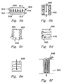
- Fig. 8a illustrates a reaction chamber 802 having a first compartment 804 having at least one dimension of about 2 mm or less, a porous catalyst material 806 and a second compartment 808.
- This reaction chamber can be used in several ways. For example, a catalyzed reaction can be carefully controlled by passing one reactant (e.g., methane) 810 into the first compartment, passing a second reactant (e.g., water) 812 into the second compartment and, in this manner, effecting a controlled reaction within the porous catalyst material 806 .
- Flow can be controlled by pressure differentials or by plugging one compartment (e.g. plug 814 ), and the product(s) formed in the porous material can be directed through outlet 816 .
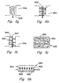
- Fig. 8k illustrates apparatus 860 where a flow distribution layer 862 (typically a sheet having random, regular, or spaced pores, slots, holes, or the like) can distribute feed 864 along a length of the reaction chamber 866.
- the reaction chamber 866 preferably contains a porous catalyst material 868 (although illustrated as a single layer along the length of the reaction chamber - thus enabling low pressure drop, it should be recognized that a porous catalyst material could have any of the configurations described herein).
- Product 870 exits the reaction chamber. Distributing the feed serves to lower the local partial pressure of one of the reactants. This has advantages for reactions that are parallel or series-parallel in nature, where the local concentration tends to favor one reaction pathway over another. For example, partial oxidation reactions can be improved by this distributed feed approach which increases selectivity to the desired product over the undesired deep oxidation products.
- Fig. 8b illustrates an embodiment of the inventive reaction chamber in which a bulk flow path 820 is disposed between porous catalyst material 822, although some flow may convectively travel through the large pores in the porous catalyst material. Flow through the large pores increases when the pore diameter of the porous insert increases and approaches an order of magnitude below the hydraulic diameter of the open area.
- This reaction chamber could be configured as a tube, with a ring or partial ring of catalyst, but is more preferably a planar arrangement.
- the planar arrangement enables economical stacking of reaction chambers with other components such as: additional reaction chambers, heat exchangers, etc.
- the contiguous, straight-through configuration of the bulk flow channel creates the opportunity to perform gas phase catalysis with low pressure drops.
- Figs. 8c and 8d illustrate reaction chamber configurations in which corrugated catalyst inserts 826 provide high surface area for gas phase catalysis while contiguous flow paths 828, 832 enable catalysis to be performed with low pressure drops.
- the inserts 826 either have a surface coating of a porous catalyst material or, preferably, are comprised of a porous catalyst material.
- Fig. 9d A similar configuration is illustrated in Fig. 9d.
- Fig. 8e illustrates an embodiment in which a corrugated porous catalyst material 826 is disposed in the reaction chamber such that gas flow is partially through, and around the catalyst. This configuration ensures contact with the porous catalyst; however, this configuration has the disadvantage of significantly higher pressure drops but the advantage of more intimate contact of the reactants with the active catalyst surface.
- Figs. 8f and 8g utilize catalyst fibers 836, 838. These fibers may, for example, be porous ceramic, metal or composite fibers.
- the parallel fibers 836 are preferred because they cause less of a pressure drop.
- the fibers 838 create tortuous flow through the reaction chamber. In either case, catalyst fibers are preferred over powders because they cause less pressure drop, can have better thermal conductivity, and can provide a more uniform and controlled surface for catalysis.
- the catalyst walls 840 , 842 can be ceramic (for high temperature operation), metal (for good thermal conductivity), composites, or porous catalyst (for additional reactivity and/or addition or removal of gas components).
- Figs. 8h and 8i illustrate reaction chambers with baffles 846 , 848.
- Baffles 846 comprise plates or rods composed of a porous catalyst material or that are coated with a porous catalyst material.
- Baffles 848 comprise plates or rods composed of a porous catalyst material.
- Flow can either be parallel 849 or nonparallel 847 or differing reactants can flow in differing directions (e.g. orthogonal reactant flows). In either case, there is a contiguous bulk flow through the chamber.
- These baffles can create turbulence and enhance contact of gaseous reactants with a catalyst.
- the baffles which preferably comprise a thermally conductive metal, provide good heat transport to (or from) the reactor walls.
- the reaction chamber walls 854 may be of the same materials described above for walls 842.
- Fig. 8j illustrates a porous catalyst matrix material 850 within which there are contiguous bulk flow channels 852.
- the matrix 850 can be the reaction chamber walls or the entire article 855 can be an insert that fits into an opening.
- the matrix material contains 1 to 10,000 more preferably 5 to 1000 bulk flow channels 852.
- the bulk flow channels 852 are essentially straight. In another embodiment, these channels are tortuous. In yet another embodiment, the channels 852 are filled with a catalyst material and bulk flow of reactants and products is primarily through the matrix.
- Fig. 9a illustrates a reactor 902 with reaction tubes/chambers 904, each of which may contain a porous catalyst material (not shown) in any of the configurations described herein.
- a bulk flow volume 906 On the outside of these tubes is a bulk flow volume 906.
- a heat exchange fluid flows through the bulk flow volume; flow of the heat exchange fluid can be cross-flow, concurrent flow or counterflow to the flow of gaseous reactants and products.
- Fig. 9b illustrates a configuration in which a porous catalyst material 908 is disposed within the reaction chamber without direct contact to the reaction chamber walls 910.
- the material 908 comprises a core of a large pore structure (in which molecular diffusion occurs) and a small pore structure (through which Knudsen diffusion occurs) on the outer sides.
- Catalyst may be coated on the small pore structure, or on the large pore structure, or on both.
- Fig. 9c illustrates a reaction chamber 911 having a bulk flow path 912 and porous catalyst material 914, 916.
- the porous plug 916 serves to provide catalyst contact to any gaseous reactants that remain unreacted after passage through bulk flow path 912.
- the flow regime in this example, and in other figures, is typically laminar based upon the classical definition of the Reynolds number less than 2000. Although the flow regime may also be transitional or turbulent in the microchannels, this is less common. For laminar flow, there will be reactants that move along the centerline of the channel. Not all molecules may have an opportunity to diffuse to the porous catalyst and react. For those molecules that do not diffuse to the wall to react, this is referred to as 'slip'. The overall reactor conversion may thus be a few percentage points lower than equilibrium would suggest attainable.
- the use of the porous catalyst material through the entire cross section for a fraction of the reactor length serves to reduce slip and enable overall conversions with a closer approach to equilibrium.
- Fig. 9c illustrates a reactor comprised of multi reaction chambers 922 and a mixing chamber 924.
- the mixing chamber combines gases from at least two reaction chambers 922.
- the mixing chamber helps to equalize concentration between multiple reaction chambers by mixing the possibly laminar flow streamlines and helps to ensure a higher overall conversion than if the at least two reaction chambers were joined into one chamber by reducing the centerline slip of reactants.
- Fig. 9e illustrates a reactor in which the bulk flow from at least two reaction chambers 930, 932 flow into porous material 934.
- flow enters through flow path 930, through porous material 934 and out through flow path 932.
- This embodiment also serves to reduce the possible slip of reactants and bring the overall reactor conversion closer to that predicted at equilibrium.
- Fig. 9f illustrates a forked configuration in which a gaseous reactant enters a first compartment 936, having a dimension of about 2 mm or less, and convectively travels past porous catalyst material 938 and then travels convectively through porous catalyst material 940. While traveling in compartment 936, the feed may diffuse to the porous catalyst and react. The gas exiting the porous catalyst material 940 flows into second compartments 942. The compartments 936 and 942 may or may not be offset. By offsetting porous dividers 938, the gas flows in adjacent first compartments are further mixed to reduce the slip of reactants.
- Fig. 9g illustrates a flow configuration where the feed flows along one side of a porous catalyst in the first flow path, makes at least one bend, and then travels back along the other side of the porous catalyst in the opposite flow direction to form at least one second flow path.
- a second catalyst may be used for the second flow path.
- a wall may separate the porous catalysts used in the first and second flowpath.
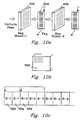
- Fig. 10a-10c illustrates another aspect of the invention in which a heat exchanger 504 is disposed between two layers of porous catalyst sheets 502, 506.
- the layers may be assembled as sheets or as an integrated device.
- a gas exiting the first porous catalyst sheet 502 then passes through at least one array of microchannels in the heat exchanger 504 and travels toward the second porous catalyst sheet 506.
- a separate heat exchange fluid is preferred in heat exchanger 504 to either remove heat from an exothermic reaction in chamber 502 or to add heat for the case of an endothermic reaction in chamber 502 .
- the flow of heat exchange fluid may be either co-current, countercurrent, or cross current.
- the heat exchanger 502 could operate in a recuperative heat exchange mode, whereby the cold reactants could be preheated in at least one first array of microchannels in heat exchanger 504, then fed to the reaction chamber in 502 to undergo an exothermic reaction, and then cooled in at least one second array of microchannels in heat exchanger 504 that is exchanging heat with the first array of microchannels in heat exchanger 504.
- the product mixture from the first reaction chamber 502 that travels through the heat exchange chamber 504 may then travel to at least one second reaction chamber 506 to undergo a different or similar reaction.
- This alternating structure can be repeated any number of desired layers.
- the layers shown in Fig. 10a can be laminated and walls placed around the laminate to form a reactor.
- the reactor has appropriate openings, valves, etc. to control input of reactants output of products and flow of heat exchange fluids.
- the porous catalyst layers can be the same or can be different.
- products from the first catalyst layer 502 can be subjected to a second reaction (different from the first reaction) possibly with the use of one or more porous catalysts (different from the catalyst on the first layer) at the second sheet 506 to form a different product.
- the porous catalyst layers must be sufficiently porous to permit the flow of gases through the layers and preferably, these layers are comprised of the porous catalyst material described herein.
- the smallest width or height dimension of these channels is 0.1 micrometer to about 2 mm, preferably 0.3 micrometers to 2 mm.
- a porous catalyst material is disposed in the layers such that gas moving through the layers contacts the porous catalyst material.
- These channels could also be any of the reaction chambers described herein.
- the length of channels can be any length including less than 2mm.
- the invention can be defined to include a chemical reactor including one porous catalyst layer 502 and a heat exchanger 504.
- fluid flow through the heat exchanger can be directed into a reaction chamber such as any of the reaction chambers described herein.
- the heat exchanger is preferably a microchannel heat exchanger.
- the laminate can be configured such that a portion of flow from any layer can be recycled back upstream to again flow through all or part of the laminate. Recycle may be desired to raise the conversion if thermodynamically attainable. As an alternate configuration, the product may be separated from the unreacted feeds while on the recycle path back to an earlier reaction section.
- a product may be separated from the reaction chamber 520 as it is formed through the use of an active separating agent 522 such as a membrane or sorbent.
- an active separating agent 522 such as a membrane or sorbent.
- the continuous removal of products can drive otherwise equilibrium-limited reactions to completion.
- the products diffusing out of the porous catalyst 524 may further diffuse across the open area 526 to the active separating agent on the opposing wall.
- the separating agent 522 can be a palladium membrane for the selective removal of hydrogen gas.
- the products may diffuse through the porous catalyst to the adjacent wall which is also an active separating agent.
- the microchannel was placed within a tube furnace to provide the required endothermic reaction heat.
- the microchannel was 1.52-cm long and 0.66-cm high.
- the width (or opening) of the microchannel was 0.0762-cm or 762-microns.
- the 0.0762-cm width included two porous structures that covered opposite walls and each had a width of 254-microns leaving a bulk flow path between the two porous structures of 254 microns.
- the porous structure contained a catalyst of 13.8%-Rh/6%-MgO/Al 2 O 3 on a metal felt of FeCrAl alloy obtained from Technetics, Deland, Florida.
- 13.8wt%Rh6wt%MgO/Al 2 O 3 powdered catalyst was prepared by 1) calcining a high surface area gamma-alumina at 500°C for 5 hours; 2) impregnating the gamma alumina with MgO using the incipient wetness method with an aqueous solution of magnesium nitrate; and obtaining an MgO modified gamma alumina support; 3) drying the modified support at 110°C for 4 hours followed by 4) a second calcination at 900°C for 2 hours; 5) impregnating the modified support with Rh 2 O 3 with the incipient wetness method from a rhodium nitrate solution; 6) followed by a final drying at 110°C for 4 hours and a 7) final calcinations at 500°C for 3 hours to obtain a powder of the supported catalyst.
- the powdered catalyst was ball-milled overnight and slurry dip-coated on the FeCrAl felt until the desired loading is achieved.
- the coated catalyst was dried at 90°C overnight and calcined at 350°C for four hours. Prior to the catalyst evaluation, catalyst was reduced in 10%H 2 /N 2 (100cc(STP)/min) at 110°C for four hours.
- the methane inlet flowrate was 50.3-cc/min at standard conditions and the water (liquid) flowrate was 7.3 mL/hr, corresponding to a steam to carbon ratio of approximately 3:1.
- the methane and water were preheated to near the reaction temperature before entering the microchannel. Gas flow was in the bulk flow path between the porous structures had a Reynold's number less than about 500, and molecular diffusion brought reactants and products to and from each pore surface containing the catalyst.
- Results are shown in Table 1-1 of performance as a function of temperature for very short residence times (less than 10-milliseconds). Performance data in single microchannel Temperature Residence time (milliseconds) Methane conversion (%) CO selectivity (%) Pressure drop (psi) 650 2.3 54.2 42.3 0.05 700 2.2 70.9 50.9 0.13 800 2.0 88.9 65.4 0.45 900 1.8 89.6 74.6 1.00
- FIG. 7a An experiment was conducted utilizing apparatus illustrated in FIG. 7a including a fuel combustor 700 , water vaporizer 702 , a reactant preheat heat exchanger 704 , and a steam-reforming unit 706 .
- the steam reforming unit 706 was constructed with 12 parallel channels ( FIG. 7b ) 1, 2, 3 ... 12 each of length 2.79 cm, height 2.54 cm, and width of 750 microns.
- the porous structure 106 was felt FeCrAl alloy with a porosity ranging from 35% to 90% obtained from Technetics, Orlando, Florida, having a width of about 250 micron. Pieces of metal felt with length and height nearly equal to the channel length and height were coated with the catalyst using the same slurry dipping method and powder catalyst as described in Example 1.
- the reactor microchannels were interspersed with heat exchange channels a, b, c ... m to provide the endothermic reaction heat.
- the adjacent (and interleaved) parallel heat exchange microchannels (13 total) were hermetically sealed with respect to the reaction microchannels to prevent reactant by-pass around the catalyst material.
- the heat exchange microchannels had nearly the same height and length as the reaction microchannels.
- the width of each heat exchange channel was 508-microns.
- the heat exchange fluid 402 within the steam-reforming unit was the combustion product of hydrogen (20 SLPM feed) and excess air (168 SLPM feed). The combustion product 402 was fed in a cross-flow configuration to the direction of reactant flow 102 .
- Reactants were methane and water in the form of steam at flow rates of 1 SLPM and 2.81-SLPM (or 2.26-ml/min liquid) respectively.
- Gas hourly space velocity was approximately 100,000 hr -1 corresponding to a residence time of 9.2 milliseconds.
- Reactor inlet temperature was 736 °C receiving a mixture of methane and steam.
- the pressure drop through the microchannel steam-reforming unit was less than 0.6 psi.
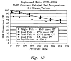
- Catalyst was inserted within the single channel device with a snug fit. All catalysts were evaluated in a single channel device. The single channel device is placed in a tube furnace. Reactants were preheated in the top zone of the furnace, and were introduced into the single channel device in a down-flow mode. Steam reforming of methane was conducted at a fixed contact time, a steam-to-carbon ratio of 2/1, and a temperature maintained at 850°C (chamber temperature was continuously monitored by a thermocouple). Effluent flowrate was measured by a bubble flowmeter, and product was analyzed using gas chromatography. The catalyst configurations tested and direction of flow is illustrated on the bottom of Fig. 11. Pressure ranged from 0 to 350 psig. For all experiments described in Example 3, the measured pressure drop across the engineered catalyst was less than 0.2 psig. Contact time is defined as the total feed gas volume at standard temperature and pressure divided by the catalyst chamber volume.
- Each of the felt catalysts in the double felt configuration have the identical dimensions as that of the single felt (0.01"x0.35"x2''), and were evaluated in a single channel device (0.03"x 0.35"x 2" / 0.075 cm x 0.88 cm x 5.0 cm). Two felts with a gap of 0.01" were placed in the single channel device so that both felts were in close contact with the walls. Again, the catalyst chamber volume is defined as the single channel volume.
- Felt with a thickness of 0.01" (0.025 cm) was crimped into a corrugated form, and is called a ruffle.
- Ruffles studied in this work have a fixed wave length of 0.117" (0.295 cm) and a fixed amplitude of 0.05" (0.127 cm).
- the dimensions of ruffle are 0.35" (0.88 cm) in width and 2" (8.0 cm) length. Reactants flow in the direction perpendicular to the waves.
- Single ruffle was snug-fitted into a single channel device (0.05"x0.35"x2"), which confines the catalyst chamber volume.
- Double ruffle configuration is designed by stacking two identical ruffles with a shim (0.01"x 0.35"x 2" / 0.025 cm x 0.88 cm x 5.0 cm) in between. Double ruffle was evaluated in a wider single channel device (0.11" x 0.35"x 2"/ 0.28 cm x 0.88 cm x 5.0 cm), which confines the catalyst chamber volume. Experimental data are shown in Figures 11-12. For this data the experimental error was about 5%. For comparison purposes, equilibrium conversions are also included in these figures under the conditions studied. Over the pressure range investigated, all four catalyst structures exhibit fairly high activities as indicated by high conversions (>50%) at short contact times ( ⁇ 50ms).
- Figure 12 compares the activity between single felt and double felts. Under the identical conditions except the contact time, activity of single felt is still lower than that of double felts even though the contact time is three time longer (45.9ms vs 13.75ms).
- Figure 11 compares the activity between single ruffle and double-ruffles. Under the identical conditions (15ms contact), single ruffle shows 10% higher conversions than double-ruffles. Figure 11 shows that at an identical contact time (7.5ms), dual felts out-perform single ruffle by at least 10%.
Landscapes
- Chemical & Material Sciences (AREA)
- Organic Chemistry (AREA)
- Chemical Kinetics & Catalysis (AREA)
- Engineering & Computer Science (AREA)
- Inorganic Chemistry (AREA)
- Combustion & Propulsion (AREA)
- General Health & Medical Sciences (AREA)
- Materials Engineering (AREA)
- Health & Medical Sciences (AREA)
- Life Sciences & Earth Sciences (AREA)
- Analytical Chemistry (AREA)
- Manufacturing & Machinery (AREA)
- Sustainable Development (AREA)
- Sustainable Energy (AREA)
- Electrochemistry (AREA)
- General Chemical & Material Sciences (AREA)
- Physical Or Chemical Processes And Apparatus (AREA)
- Hydrogen, Water And Hydrids (AREA)
- Separation Using Semi-Permeable Membranes (AREA)
- Organic Low-Molecular-Weight Compounds And Preparation Thereof (AREA)
- Catalysts (AREA)
- Devices And Processes Conducted In The Presence Of Fluids And Solid Particles (AREA)
Applications Claiming Priority (5)
| Application Number | Priority Date | Filing Date | Title |
|---|---|---|---|
| US09/375,614 US6488838B1 (en) | 1999-08-17 | 1999-08-17 | Chemical reactor and method for gas phase reactant catalytic reactions |
| US375614 | 1999-08-17 | ||
| US640903 | 2000-08-16 | ||
| US09/640,903 US6680044B1 (en) | 1999-08-17 | 2000-08-16 | Method for gas phase reactant catalytic reactions |
| EP00955739A EP1206316B1 (de) | 1999-08-17 | 2000-08-17 | Chemischer reaktor und verfahren zur katalytischen gasphasenreaktionen |
Related Parent Applications (2)
| Application Number | Title | Priority Date | Filing Date |
|---|---|---|---|
| EP00955739A Division EP1206316B1 (de) | 1999-08-17 | 2000-08-17 | Chemischer reaktor und verfahren zur katalytischen gasphasenreaktionen |
| EP00955739.8 Division | 2000-08-17 |
Publications (2)
| Publication Number | Publication Date |
|---|---|
| EP1568412A1 true EP1568412A1 (de) | 2005-08-31 |
| EP1568412B1 EP1568412B1 (de) | 2012-05-09 |
Family
ID=23481586
Family Applications (1)
| Application Number | Title | Priority Date | Filing Date |
|---|---|---|---|
| EP05007860A Revoked EP1568412B1 (de) | 1999-08-17 | 2000-08-17 | Verfahren zur Dampfreformierung von Kohlenwasserstoffen |
Country Status (9)
| Country | Link |
|---|---|
| US (4) | US6488838B1 (de) |
| EP (1) | EP1568412B1 (de) |
| JP (2) | JP4904480B2 (de) |
| AT (1) | ATE556769T1 (de) |
| CA (1) | CA2641757C (de) |
| DK (1) | DK1568412T3 (de) |
| ES (1) | ES2386506T3 (de) |
| NO (1) | NO330178B1 (de) |
| ZA (1) | ZA200200864B (de) |
Cited By (4)
| Publication number | Priority date | Publication date | Assignee | Title |
|---|---|---|---|---|
| WO2006042598A1 (de) * | 2004-10-15 | 2006-04-27 | Uhde Gmbh | Verfahren zur herstellung von olefinoxiden und peroxiden, reaktor und dessen verwendung |
| WO2006079532A1 (en) * | 2005-01-28 | 2006-08-03 | Umicore Ag & Co. Kg | Ceramic microreactor built from layers and having at least 3 interior spaces as well as buffers |
| BE1017728A5 (fr) * | 2006-08-18 | 2009-05-05 | Linde Ag | Procede et dispositif de desalkylation a la vapeur dans une unite de craquage catalytique d'hydrocarbures. |
| CN112351835A (zh) * | 2018-07-13 | 2021-02-09 | 三菱重工工程株式会社 | 催化剂反应器 |
Families Citing this family (167)
| Publication number | Priority date | Publication date | Assignee | Title |
|---|---|---|---|---|
| US6616909B1 (en) * | 1998-07-27 | 2003-09-09 | Battelle Memorial Institute | Method and apparatus for obtaining enhanced production rate of thermal chemical reactions |
| US6440895B1 (en) | 1998-07-27 | 2002-08-27 | Battelle Memorial Institute | Catalyst, method of making, and reactions using the catalyst |
| US6946111B2 (en) * | 1999-07-30 | 2005-09-20 | Conocophilips Company | Short contact time catalytic partial oxidation process for recovering sulfur from an H2S containing gas stream |
| US6800269B2 (en) * | 1999-07-30 | 2004-10-05 | Conocophillips Company | Short contact time catalytic sulfur recovery system for removing H2S from a waste gas stream |
| US6403051B1 (en) * | 1999-07-30 | 2002-06-11 | Conoco Inc. | Recovery of sulfur from H2S and concurrent production of H2 using short contact time CPOX |
| WO2001012312A2 (en) * | 1999-08-17 | 2001-02-22 | Battelle Memorial Institute | Chemical reactor and method for catalytic gas phase reactions |
| US6969506B2 (en) * | 1999-08-17 | 2005-11-29 | Battelle Memorial Institute | Methods of conducting simultaneous exothermic and endothermic reactions |
| US6488838B1 (en) | 1999-08-17 | 2002-12-03 | Battelle Memorial Institute | Chemical reactor and method for gas phase reactant catalytic reactions |
| US6451864B1 (en) * | 1999-08-17 | 2002-09-17 | Battelle Memorial Institute | Catalyst structure and method of Fischer-Tropsch synthesis |
| WO2001012323A2 (en) * | 1999-08-17 | 2001-02-22 | Battelle Memorial Institute | Catalyst structure and method of fischer-tropsch synthesis |
| FR2807746B1 (fr) * | 2000-04-13 | 2002-12-13 | Air Liquide | Procede de production d'un melange comportant de l'hydrogene et du co |
| US7125540B1 (en) * | 2000-06-06 | 2006-10-24 | Battelle Memorial Institute | Microsystem process networks |
| US7122170B2 (en) * | 2000-07-25 | 2006-10-17 | Conocophillips Company | Catalysts for SPOC™ enhanced synthesis gas production |
| WO2002010660A1 (en) * | 2000-07-28 | 2002-02-07 | Honda Motor Co Ltd | Multi-purpose microchannel micro-component |
| US7357908B2 (en) * | 2000-12-18 | 2008-04-15 | Conocophillips Company | Apparatus and catalytic partial oxidation process for recovering sulfur from an H2S-containing gas stream |
| US7326397B2 (en) * | 2000-12-18 | 2008-02-05 | Conocophillips Company | Catalytic partial oxidation process for recovering sulfur from an H2S-containing gas stream |
| US7118917B2 (en) * | 2001-03-07 | 2006-10-10 | Symyx Technologies, Inc. | Parallel flow reactor having improved thermal control |
| US6503298B1 (en) * | 2001-04-30 | 2003-01-07 | Battelle Memorial Institute | Apparatus and methods for hydrogen separation/purification utilizing rapidly cycled thermal swing sorption |
| US6746515B2 (en) | 2001-04-30 | 2004-06-08 | Battelle Memorial Institute | Method and apparatus for thermal swing adsorption and thermally-enhanced pressure swing adsorption |
| US6630012B2 (en) * | 2001-04-30 | 2003-10-07 | Battelle Memorial Institute | Method for thermal swing adsorption and thermally-enhanced pressure swing adsorption |
| US6863867B2 (en) * | 2001-05-07 | 2005-03-08 | Uop Llc | Apparatus for mixing and reacting at least two fluids |
| FR2826293B1 (fr) * | 2001-06-21 | 2004-01-30 | Elf Antar France | Procede d'obtention de gaz de synthese par oxydation catalytique partielle |
| GB0116894D0 (en) * | 2001-07-11 | 2001-09-05 | Accentus Plc | Catalytic reactor |
| US7326669B2 (en) * | 2001-09-20 | 2008-02-05 | Honda Motor Co., Ltd. | Substrate having catalyst compositions on surfaces of opposite sides |
| US7201883B2 (en) * | 2001-10-12 | 2007-04-10 | Compactgtl Plc | Catalytic reactor |
| GB0124999D0 (en) * | 2001-10-18 | 2001-12-05 | Accentus Plc | Catalytic reactor |
| GB0125035D0 (en) * | 2001-10-18 | 2001-12-12 | Accentus Plc | Catalytic reactor |
| AU2002349143A1 (en) * | 2001-12-05 | 2003-06-17 | GTL Mircosystems AG | Process an apparatus for steam-methane reforming |
| GB0129054D0 (en) * | 2001-12-05 | 2002-01-23 | Accentus Plc | Catalytic reactor and process |
| US7297324B2 (en) * | 2002-03-11 | 2007-11-20 | Battelle Memorial Institute | Microchannel reactors with temperature control |
| US6746657B2 (en) * | 2002-03-12 | 2004-06-08 | Precision Combustion, Inc. | Method for reduced methanation |
| US8206666B2 (en) * | 2002-05-21 | 2012-06-26 | Battelle Memorial Institute | Reactors having varying cross-section, methods of making same, and methods of conducting reactions with varying local contact time |
| US7402719B2 (en) * | 2002-06-13 | 2008-07-22 | Velocys | Catalytic oxidative dehydrogenation, and microchannel reactors for catalytic oxidative dehydrogenation |
| ATE340642T1 (de) * | 2002-08-15 | 2006-10-15 | Velocys Inc | Verfahren in mikrokanalreaktoren mit gebundenem katalysator und einen gebundenen katalysator oder gebundene chirale hilfsmittel enthaltende systeme |
| US9192929B2 (en) | 2002-08-15 | 2015-11-24 | Velocys, Inc. | Integrated combustion reactor and methods of conducting simultaneous endothermic and exothermic reactions |
| US6622519B1 (en) * | 2002-08-15 | 2003-09-23 | Velocys, Inc. | Process for cooling a product in a heat exchanger employing microchannels for the flow of refrigerant and product |
| US6969505B2 (en) * | 2002-08-15 | 2005-11-29 | Velocys, Inc. | Process for conducting an equilibrium limited chemical reaction in a single stage process channel |
| US7014835B2 (en) | 2002-08-15 | 2006-03-21 | Velocys, Inc. | Multi-stream microchannel device |
| US7250151B2 (en) * | 2002-08-15 | 2007-07-31 | Velocys | Methods of conducting simultaneous endothermic and exothermic reactions |
| US7404936B2 (en) * | 2002-10-22 | 2008-07-29 | Velocys | Catalysts, in microchannel apparatus, and reactions using same |
| US7118920B2 (en) * | 2002-10-22 | 2006-10-10 | Battelle Memorial Institute | Multiphasic microchannel reactions |
| US20040112571A1 (en) * | 2002-11-01 | 2004-06-17 | Cooligy, Inc. | Method and apparatus for efficient vertical fluid delivery for cooling a heat producing device |
| US8464781B2 (en) * | 2002-11-01 | 2013-06-18 | Cooligy Inc. | Cooling systems incorporating heat exchangers and thermoelectric layers |
| US20050211418A1 (en) * | 2002-11-01 | 2005-09-29 | Cooligy, Inc. | Method and apparatus for efficient vertical fluid delivery for cooling a heat producing device |
| GB0314790D0 (en) * | 2003-06-25 | 2003-07-30 | Accentus Plc | Catalytic reactor and process |
| US7326394B2 (en) * | 2003-03-07 | 2008-02-05 | Velocys | Catalysts, methods of making catalysts, and methods of combustion |
| US20040182551A1 (en) * | 2003-03-17 | 2004-09-23 | Cooligy, Inc. | Boiling temperature design in pumped microchannel cooling loops |
| US7405338B2 (en) * | 2003-04-07 | 2008-07-29 | Velocys | Dehydrogenation reactions in narrow reaction chambers and integrated reactors |
| US7294734B2 (en) * | 2003-05-02 | 2007-11-13 | Velocys, Inc. | Process for converting a hydrocarbon to an oxygenate or a nitrile |
| US8580211B2 (en) * | 2003-05-16 | 2013-11-12 | Velocys, Inc. | Microchannel with internal fin support for catalyst or sorption medium |
| JP2007504635A (ja) | 2003-05-16 | 2007-03-01 | バッテル・メモリアル・インスティチュート | 迅速始動燃料改質システム及び技術 |
| US7485671B2 (en) * | 2003-05-16 | 2009-02-03 | Velocys, Inc. | Process for forming an emulsion using microchannel process technology |
| JP4611989B2 (ja) * | 2003-05-16 | 2011-01-12 | ヴェロシス,インク. | マイクロチャネルプロセス技術を用いてエマルジョンを作製するプロセス |
| US7220390B2 (en) * | 2003-05-16 | 2007-05-22 | Velocys, Inc. | Microchannel with internal fin support for catalyst or sorption medium |
| US20050203195A1 (en) * | 2003-08-05 | 2005-09-15 | Yong Wang | Tailored Fischer-Tropsch synthesis product distribution |
| JP4578867B2 (ja) * | 2003-09-30 | 2010-11-10 | 株式会社日立製作所 | 水素貯蔵・供給装置とそのシステム及びそれを用いた分散電源並びに自動車 |
| US8066955B2 (en) * | 2003-10-17 | 2011-11-29 | James M. Pinchot | Processing apparatus fabrication |
| US7470408B2 (en) * | 2003-12-18 | 2008-12-30 | Velocys | In situ mixing in microchannels |
| US7029647B2 (en) * | 2004-01-27 | 2006-04-18 | Velocys, Inc. | Process for producing hydrogen peroxide using microchannel technology |
| US7084180B2 (en) * | 2004-01-28 | 2006-08-01 | Velocys, Inc. | Fischer-tropsch synthesis using microchannel technology and novel catalyst and microchannel reactor |
| US9023900B2 (en) | 2004-01-28 | 2015-05-05 | Velocys, Inc. | Fischer-Tropsch synthesis using microchannel technology and novel catalyst and microchannel reactor |
| US20050175519A1 (en) | 2004-02-06 | 2005-08-11 | Rogers William A.Jr. | Microchannel compression reactor |
| US8747805B2 (en) * | 2004-02-11 | 2014-06-10 | Velocys, Inc. | Process for conducting an equilibrium limited chemical reaction using microchannel technology |
| US7520917B2 (en) * | 2004-02-18 | 2009-04-21 | Battelle Memorial Institute | Devices with extended area structures for mass transfer processing of fluids |
| KR100828489B1 (ko) * | 2004-03-01 | 2008-05-13 | 다이니폰 인사츠 가부시키가이샤 | 마이크로 리액터 및 그 제조 방법 |
| JP4580664B2 (ja) * | 2004-03-01 | 2010-11-17 | 大日本印刷株式会社 | マイクロリアクターおよびその製造方法 |
| US8378163B2 (en) * | 2004-03-23 | 2013-02-19 | Velocys Corp. | Catalysts having catalytic material applied directly to thermally-grown alumina and catalytic methods using same, improved methods of oxidative dehydrogenation |
| JP4590202B2 (ja) * | 2004-04-02 | 2010-12-01 | 日産自動車株式会社 | 燃料改質反応器 |
| US7572432B2 (en) * | 2004-04-13 | 2009-08-11 | General Electric Company | Method and article for producing hydrogen gas |
| US7304198B2 (en) | 2004-05-14 | 2007-12-04 | Battelle Memorial Institute | Staged alkylation in microchannels |
| US7616444B2 (en) | 2004-06-04 | 2009-11-10 | Cooligy Inc. | Gimballed attachment for multiple heat exchangers |
| CA2574113C (en) | 2004-07-23 | 2014-02-18 | Anna Lee Tonkovich | Distillation process using microchannel technology |
| US7305850B2 (en) * | 2004-07-23 | 2007-12-11 | Velocys, Inc. | Distillation process using microchannel technology |
| EP1786797B1 (de) | 2004-08-12 | 2014-11-26 | Velocys, Inc. | Verfahren zur umwandlung von ethylen in ethylenoxid unter anwendung einer mikrokanalverfahrenstechnologie |
| US8517717B2 (en) * | 2004-08-13 | 2013-08-27 | Velocys, Inc. | Detonation safety in microchannels |
| EP1804964A1 (de) | 2004-10-01 | 2007-07-11 | Velocys Inc. | Mehrphasiges mischverfahren mit mikrokanalverarbeitungstechnologie |
| US7468455B2 (en) * | 2004-11-03 | 2008-12-23 | Velocys, Inc. | Process and apparatus for improved methods for making vinyl acetate monomer (VAM) |
| WO2006053345A1 (en) | 2004-11-12 | 2006-05-18 | Velocys Inc. | Process using microchannel technology for conducting alkylation or acylation reaction |
| CN101132854B (zh) | 2004-11-16 | 2011-07-06 | 万罗赛斯公司 | 使用微通道技术的多相反应方法 |
| CN101132853B (zh) * | 2004-11-17 | 2012-05-09 | 万罗赛斯公司 | 使用微通道处理技术的乳化方法 |
| US7569085B2 (en) * | 2004-12-27 | 2009-08-04 | General Electric Company | System and method for hydrogen production |
| US7485161B2 (en) * | 2005-01-04 | 2009-02-03 | Air Products And Chemicals, Inc. | Dehydrogenation of liquid fuel in microchannel catalytic reactor |
| KR20060080385A (ko) | 2005-01-05 | 2006-07-10 | 삼성에스디아이 주식회사 | 연료 전지 시스템, 개질기, 반응 기판 및 그 반응 기판의제조 방법 |
| GB0501731D0 (en) * | 2005-01-31 | 2005-03-02 | Accentus Plc | Catalytic reactor |
| WO2006094190A2 (en) | 2005-03-02 | 2006-09-08 | Velocys Inc. | Separation process using microchannel technology |
| WO2006099573A1 (en) * | 2005-03-16 | 2006-09-21 | Fuelcor Llc | Systems, methods, and compositions for production of synthetic hydrocarbon compounds |
| US9101890B2 (en) | 2005-05-25 | 2015-08-11 | Velocys, Inc. | Support for use in microchannel processing |
| WO2006138211A2 (en) * | 2005-06-17 | 2006-12-28 | University Of Delaware | Catalytic microcombustors for compact power or heat generation |
| US8216323B2 (en) * | 2005-06-30 | 2012-07-10 | General Electric Company | System and method for hydrogen production |
| US20070004810A1 (en) * | 2005-06-30 | 2007-01-04 | Yong Wang | Novel catalyst and fischer-tropsch synthesis process using same |
| EP1904223A2 (de) | 2005-07-08 | 2008-04-02 | Velocys Inc. | Verfahren für eine katalytische reaktion unter verwendung von mikrokanaltechnologie |
| ATE540000T1 (de) * | 2005-08-31 | 2012-01-15 | Fmc Corp | Autoxidative herstellung von wasserstoffperoxid mittels oxidation in einem mikroreaktor |
| JP2009529479A (ja) * | 2005-08-31 | 2009-08-20 | エフ エム シー コーポレーション | マイクロリアクター中での水素化による過酸化水素の自動酸化 |
| US7943547B2 (en) * | 2005-09-14 | 2011-05-17 | Hamilton Sundstrand Space Systems International, Inc. | Selective catalytic oxidation of ammonia to water and nitrogen |
| JP5081830B2 (ja) * | 2005-10-13 | 2012-11-28 | ヴェロシス インコーポレイテッド | マイクロチャンネルにおける無電解めっき法 |
| US7750170B2 (en) * | 2005-12-22 | 2010-07-06 | Shell Oil Company | Process for mixing an oxidant having explosive potential with a hydrocarbon |
| US20070154377A1 (en) * | 2005-12-22 | 2007-07-05 | Rekers Dominicus M | Process for the removal of combustible volatile contaminant materials from a process stream |
| ZA200610755B (en) * | 2005-12-22 | 2008-05-28 | Shell Int Research | A process for the preparation of an olefin oxide or a chemical derivable from an olefin oxide |
| US20070197808A1 (en) * | 2005-12-22 | 2007-08-23 | Bolk Jeroen W | Method Of Installing An Epoxidation Catalyst In A Reactor, A Method Of Preparing An Epoxidation Catalyst, An Epoxidation Catalyst, A Process For The Preparation Of An Olefin Oxide Or A Chemical Derivable From An Olefin Oxide, And A Reactor Suitable For Such A Process |
| US7459589B2 (en) * | 2005-12-22 | 2008-12-02 | Shell Oil Company | Process for the preparation of an alkylene glycol |
| US20070213545A1 (en) * | 2005-12-22 | 2007-09-13 | Bolk Jeroen W | Method Of Installing An Epoxidation Catalyst In A Reactor, A Method Of Preparing An Epoxidation Catalyst, An Epoxidation Catalyst, A Process For The Preparation Of An Olefin Oxide Or A Chemical Derivable From An Olefin Oxide, And A Reactor Suitable For Such A Process |
| US20070203349A1 (en) * | 2005-12-22 | 2007-08-30 | Bolk Jeroen W | Method Of Installing An Epoxidation Catalyst In A Reactor, A Method Of Preparing An Epoxidation Catalyst, An Epoxidation Catalyst, A Process For The Preparation Of An Olefin Oxide Or A Chemical Derivable From An Olefin Oxide, And A Reactor Suitable For Such A Process |
| US20070203350A1 (en) * | 2005-12-22 | 2007-08-30 | Bolk Jeroen W | Method Of Installing An Epoxidation Catalyst In A Reactor, A Method Of Preparing An Epoxidation Catalyst, An Epoxidation Catalyst, A Process For The Preparation Of An Olefin Oxide Or A Chemical Derivable From An Olefin Oxide, And A Reactor Suitable For Such A Process |
| US20070151451A1 (en) * | 2005-12-22 | 2007-07-05 | Rekers Dominicus M | Process for the cooling, concentration or purification of ethylene oxide |
| US20070203352A1 (en) * | 2005-12-22 | 2007-08-30 | Bolk Jeroen W | Method Of Installing An Epoxidation Catalyst In A Reactor, A Method Of Preparing An Epoxidation Catalyst, An Epoxidation Catalyst, A Process For The Preparation Of An Olefin Oxide Or A Chemical Derivable From An Olefin Oxide, And A Reactor Suitable For Such A Process |
| US20070197801A1 (en) * | 2005-12-22 | 2007-08-23 | Bolk Jeroen W | Method of installing an epoxidation catalyst in a reactor, a method of preparing an epoxidation catalyst, an epoxidation catalyst, a process for the preparation of an olefin oxide or a chemical derivable from an olefin oxide, and a reactor suitables for such a process |
| US7913719B2 (en) * | 2006-01-30 | 2011-03-29 | Cooligy Inc. | Tape-wrapped multilayer tubing and methods for making the same |
| US7226572B1 (en) * | 2006-03-03 | 2007-06-05 | Conocophillips Company | Compact sulfur recovery plant and process |
| WO2007111997A2 (en) * | 2006-03-23 | 2007-10-04 | Velocys Inc. | Process for making styrene using microchannel process technology |
| CA2649388A1 (en) | 2006-04-20 | 2007-11-01 | Velocys, Inc. | Process for treating and/or forming a non-newtonian fluid using microchannel process technology |
| US7709541B2 (en) * | 2006-07-14 | 2010-05-04 | Headwaters Technology Innovation, Llc | Fischer-Tropsch catalysts incorporating promoter for increasing yields of C5+ hydrocarbons and methods for making and using same |
| US7501111B2 (en) | 2006-08-25 | 2009-03-10 | Conoco Phillips Company | Increased capacity sulfur recovery plant and process for recovering elemental sulfur |
| US7999144B2 (en) | 2006-09-01 | 2011-08-16 | Velocys | Microchannel apparatus and methods of conducting catalyzed oxidative dehydrogenation |
| US7820725B2 (en) | 2006-09-05 | 2010-10-26 | Velocys, Inc. | Integrated microchannel synthesis and separation |
| US8497308B2 (en) * | 2006-09-05 | 2013-07-30 | Velocys, Inc. | Integrated microchannel synthesis and separation |
| EP2104755A4 (de) * | 2006-10-26 | 2011-01-12 | Symyx Solutions Inc | Hochdruck-parallel-festbettreaktor und verfahren dafür |
| US20080154052A1 (en) * | 2006-12-20 | 2008-06-26 | Jeroen Willem Bolk | Method of installing an epoxidation catalyst in a reactor, a method of preparing an epoxidation catalyst, an epoxidation catalyst, a process for the preparation of an olefin oxide or a chemical derivable from an olefin oxide, and a reactor suitable for such a process |
| US20080154051A1 (en) * | 2006-12-20 | 2008-06-26 | Jeroen Willem Bolk | Method of installing an epoxidation catalyst in a reactor, a method of preparing an epoxidation catalyst, an epoxidation catalyst, a process for the preparation of an olefin oxide or a chemical derivable from an olefin oxide, and a reactor suitable for such a process |
| WO2008079309A1 (en) | 2006-12-21 | 2008-07-03 | Ceramatec, Inc. | Catalytic microchannel reformer |
| US7923592B2 (en) | 2007-02-02 | 2011-04-12 | Velocys, Inc. | Process for making unsaturated hydrocarbons using microchannel process technology |
| JP5013514B2 (ja) * | 2007-02-09 | 2012-08-29 | 国立大学法人東京工業大学 | マイクロ反応装置および触媒反応方法 |
| US8034985B2 (en) * | 2007-02-15 | 2011-10-11 | Honeywell International, Ltd. | Catalyst for the synthesis of CF3CF2I |
| US8603407B2 (en) | 2007-03-21 | 2013-12-10 | Precision Combustion, Inc. | Catalytic isobutane alkylation |
| GB0718398D0 (en) * | 2007-09-21 | 2007-10-31 | Robert Gordon The University | Process for the production of alcohols |
| US20090225514A1 (en) * | 2008-03-10 | 2009-09-10 | Adrian Correa | Device and methodology for the removal of heat from an equipment rack by means of heat exchangers mounted to a door |
| US8071836B2 (en) * | 2008-03-13 | 2011-12-06 | Fina Technology, Inc. | Process for toluene and methane coupling in a microreactor |
| US7745667B2 (en) * | 2008-04-07 | 2010-06-29 | Velocys | Microchannel apparatus comprising structured walls, chemical processes, methods of making formaldehyde |
| US9908093B2 (en) * | 2008-04-09 | 2018-03-06 | Velocys, Inc. | Process for converting a carbonaceous material to methane, methanol and/or dimethyl ether using microchannel process technology |
| US8100996B2 (en) * | 2008-04-09 | 2012-01-24 | Velocys, Inc. | Process for upgrading a carbonaceous material using microchannel process technology |
| US7935259B2 (en) * | 2008-07-03 | 2011-05-03 | The United States Of America As Represented By The Administrator Of The National Aeronautics And Space Administration | Filtering apparatus and method of use |
| US8343403B2 (en) * | 2008-07-16 | 2013-01-01 | The United States Of America As Represented By The Administrator Of The National Aeronautics And Space Administration | Method for making a microporous membrane |
| US8254422B2 (en) * | 2008-08-05 | 2012-08-28 | Cooligy Inc. | Microheat exchanger for laser diode cooling |
| US20100081577A1 (en) * | 2008-09-30 | 2010-04-01 | Symyx Technologies, Inc. | Reactor systems and methods |
| EP2346964A2 (de) | 2008-10-10 | 2011-07-27 | Velocys, Inc. | Verfahren und vorrichtung unter verwendung von mikrokanalverfahrenstechnik |
| JP2010210118A (ja) * | 2009-03-09 | 2010-09-24 | Jamco Corp | 漏水防止用安全弁を備えた旅客機搭載用スチームオーブン |
| EP2486107A1 (de) * | 2009-10-09 | 2012-08-15 | Velocys Inc. | Verfahren zur behandlung von schweröl |
| GB201000156D0 (en) * | 2010-01-07 | 2010-02-24 | Gas2 Ltd | Isothermal reactor for partial oxidisation of methane |
| US9950305B2 (en) | 2011-07-26 | 2018-04-24 | Battelle Memorial Institute | Solar thermochemical processing system and method |
| GB201214122D0 (en) | 2012-08-07 | 2012-09-19 | Oxford Catalysts Ltd | Treating of catalyst support |
| DE102012016561B4 (de) | 2012-08-22 | 2019-05-16 | Airbus Defence and Space GmbH | Luftfahrzeug-Brennstoffzellensystem sowie Verwendung desselben |
| WO2014159555A1 (en) * | 2013-03-12 | 2014-10-02 | Battelle Memorial Institute | Reactor incorporating a heat exchanger |
| US9676623B2 (en) | 2013-03-14 | 2017-06-13 | Velocys, Inc. | Process and apparatus for conducting simultaneous endothermic and exothermic reactions |
| WO2014172592A1 (en) * | 2013-04-18 | 2014-10-23 | Honeywell International Inc. | Reaction system and process to produce fluorinated organics |
| EP3065857B1 (de) | 2013-11-06 | 2022-06-08 | Watt Fuel Cell Corp. | Integrierter cpox-reformer für brenngas und brennstoffzellensysteme sowie verfahren zur erzeugung von strom |
| KR101832864B1 (ko) | 2013-11-06 | 2018-02-27 | 와트 퓨얼 셀 코퍼레이션 | 기체 반응 매질 플로우 관리용 매니폴드를 가지는 화학 반응기 |
| WO2015069836A2 (en) | 2013-11-06 | 2015-05-14 | Watt Fuel Cell Corp. | Gaseous fuel cpox reformers and methods of cpox reforming |
| AU2014346961B2 (en) | 2013-11-06 | 2017-09-28 | Watt Fuel Cell Corp. | Reformer with perovskite as structural component thereof |
| MX352226B (es) | 2013-11-06 | 2017-11-15 | WATT Fuel Cell Corp | Sistemas de reformador cpox de combustible líquido y celdas de combustible, y métodos de producción de electricidad. |
| AU2014346831B2 (en) | 2013-11-06 | 2017-09-07 | Watt Fuel Cell Corp. | Liquid fuel CPOX reformers and methods of CPOX reforming |
| US9943819B2 (en) | 2014-11-03 | 2018-04-17 | Singh Instrument LLC | Small-scale reactor having improved mixing |
| US10458716B2 (en) | 2014-11-04 | 2019-10-29 | Roccor, Llc | Conformal thermal ground planes |
| US9937484B2 (en) | 2015-01-30 | 2018-04-10 | Battelle Memorial Institute | Reactor, CO2 sorbent system, and process of making H2 with simultaneous CO2 sorption |
| WO2016201218A2 (en) | 2015-06-12 | 2016-12-15 | Velocys, Inc. | Synthesis gas conversion process |
| EP3414000B1 (de) * | 2016-02-08 | 2024-04-10 | KT - Kinetics Technology S.p.A. | Endothermischer reaktor mit verbessertem wirkungsgrad für die synthesegaserzeugung mit flexibler wärmerückgewinnung für eine geringe exportdampferzeugung. |
| US10054140B2 (en) | 2016-02-12 | 2018-08-21 | Crystaphase Products, Inc. | Use of treating elements to facilitate flow in vessels |
| US11059278B2 (en) * | 2016-02-28 | 2021-07-13 | Roccor, Llc | Two-phase thermal management devices, methods, and systems |
| US10207241B2 (en) | 2016-11-29 | 2019-02-19 | Kontak LLC | Inductively heated microchannel reactor |
| JP6663074B2 (ja) * | 2017-02-22 | 2020-03-11 | アルプスアルパイン株式会社 | 流路チップ及び流路チップの製造方法 |
| CN108067172A (zh) * | 2018-01-17 | 2018-05-25 | 北京国能中林科技开发有限公司 | 一种适用于液态氢源材料的脱氢反应的微通道反应器及脱氢方法 |
| US11555473B2 (en) | 2018-05-29 | 2023-01-17 | Kontak LLC | Dual bladder fuel tank |
| US11638331B2 (en) | 2018-05-29 | 2023-04-25 | Kontak LLC | Multi-frequency controllers for inductive heating and associated systems and methods |
| US11358111B2 (en) | 2019-03-20 | 2022-06-14 | Battelle Memorial Institute, Pacific Northwest National Laboratories | Reactor assemblies and methods of performing reactions |
| US12383882B2 (en) | 2018-06-21 | 2025-08-12 | Battelle Memorial Institute | Reactor assemblies and methods of performing reactions |
| US12649141B2 (en) * | 2018-08-07 | 2026-06-09 | Fraunhofer-Gesellschaft zur Förderung der angewandten Forschung e.V. | Continuous flow reactor for reacting an educt |
| KR20230069085A (ko) * | 2020-07-09 | 2023-05-18 | 커먼웰쓰 사이언티픽 앤 인더스트리알 리서치 오거니제이션 | 촉매 활성 스캐폴드의 제조 방법 |
| JP2023541252A (ja) | 2020-09-09 | 2023-09-29 | クリスタフェーズ・プロダクツ・インコーポレーテッド | プロセス容器進入ゾーン |
| EP4355687A1 (de) * | 2021-06-15 | 2024-04-24 | Linde GmbH | Verfahren zur aktivierung eines katalysators |
Citations (4)
| Publication number | Priority date | Publication date | Assignee | Title |
|---|---|---|---|---|
| US5674301A (en) * | 1994-05-23 | 1997-10-07 | Ngk Insulators, Ltd. | Hydrogen preparing apparatus |
| DE19654361A1 (de) * | 1996-12-24 | 1998-06-25 | Behr Gmbh & Co | Reaktor in Stapelbauweise |
| EP0861802A2 (de) * | 1997-02-28 | 1998-09-02 | Mitsubishi Denki Kabushiki Kaisha | Vorrichtung für die Reformierung von Kraftstoffen |
| WO2000006295A1 (en) * | 1998-07-27 | 2000-02-10 | Battelle Memorial Institute | Method and apparatus for obtaining enhanced production rate of thermal chemical reactions |
Family Cites Families (97)
| Publication number | Priority date | Publication date | Assignee | Title |
|---|---|---|---|---|
| US4006102A (en) | 1975-08-25 | 1977-02-01 | Ford Motor Company | Stabilized rhenium catalyst |
| JPS551816A (en) | 1978-06-15 | 1980-01-09 | Mitsubishi Rayon Co Ltd | Vapor-liquid contactor |
| EP0025308B1 (de) | 1979-09-06 | 1984-07-11 | Imperial Chemical Industries Plc | Verfahren und Vorrichtung für den katalytischen Umsatz von Wasserdampf mit Kohlenwasserstoffen unter endothermen Bedingungen |
| CA1137962A (en) | 1980-05-20 | 1982-12-21 | Governing Council Of The University Of Toronto (The) | Heterogeneous catalyst and process for its manufacture |
| NL8200544A (nl) | 1982-02-12 | 1983-09-01 | Veg Gasinstituut Nv | Werkwijze voor de bereiding van methaan uit koolmonoxide bevattende gasmengsels met behulp van nikkel bevattende katalysatoren. |
| US4597947A (en) * | 1983-06-30 | 1986-07-01 | The United States Of America As Represented By The Secretary Of The Army | Mass transfer and material separation microchannel plate apparatus |
| DE3435319A1 (de) | 1984-09-26 | 1986-04-03 | Michael 4150 Krefeld Laumen | Katalytischer dampferzeuger |
| JPS61111140A (ja) | 1984-11-06 | 1986-05-29 | Toyota Central Res & Dev Lab Inc | 炭化水素合成用触媒 |
| DK156701C (da) | 1987-08-27 | 1990-01-29 | Haldor Topsoe As | Fremgangsmaade til gennemfoerelse af heterogene katalytiske kemiske reaktioner |
| JPH0422827Y2 (de) | 1987-09-25 | 1992-05-26 | ||
| SE462143C (sv) | 1988-03-07 | 1996-02-19 | Heraeus Gmbh W C | Katalysator för bilavgasrening, förfarande för framställning därav samt användning därav |
| DE3813946A1 (de) | 1988-04-26 | 1989-11-09 | Asea Brown Boveri | Verfahren zum aufbringen einer aus edelmetallen und/oder edelmetallverbindungen bestehenden katalysatorschicht auf einen traeger aus keramischem material |
| EP0396650B2 (de) | 1988-09-02 | 1995-04-12 | GebràDer Sulzer Aktiengesellschaft | Vorrichtung zur durchführung katalysierter reaktionen |
| US5051241A (en) | 1988-11-18 | 1991-09-24 | Pfefferle William C | Microlith catalytic reaction system |
| US5440872A (en) | 1988-11-18 | 1995-08-15 | Pfefferle; William C. | Catalytic method |
| US5047381A (en) | 1988-11-21 | 1991-09-10 | General Electric Company | Laminated substrate for catalytic combustor reactor bed |
| JPH0380937A (ja) | 1989-08-25 | 1991-04-05 | Tonen Corp | 炭化水素の水蒸気改質触媒及びその製造方法 |
| NL8902250A (nl) * | 1989-09-08 | 1991-04-02 | Veg Gasinstituut Nv | Werkwijze voor het uitvoeren van een chemische reactie en daarbij te gebruiken reactor. |
| DZ1444A1 (fr) * | 1989-09-12 | 2004-09-13 | Inst Francais Du Petrole | Procédé et réacteur d'oxydation à differentiel de perte de charge et son utilisation. |
| AU661877B2 (en) | 1990-04-03 | 1995-08-10 | Standard Oil Company, The | Endothermic reaction apparatus |
| RU2093261C1 (ru) | 1991-05-12 | 1997-10-20 | Татьяна Николаевна Довбышева | Способ получения блочного катализатора дожига водорода в присутствии паров воды |
| JP2564739Y2 (ja) * | 1991-06-21 | 1998-03-09 | 石川島播磨重工業株式会社 | 水蒸気改質器 |
| US5270127A (en) | 1991-08-09 | 1993-12-14 | Ishikawajima-Harima Heavy Industries Co., Ltd. | Plate shift converter |
| JPH05105405A (ja) | 1991-10-21 | 1993-04-27 | Ishikawajima Harima Heavy Ind Co Ltd | プレート型リフオーマ |
| IT1253064B (it) | 1991-12-13 | 1995-07-10 | Unicoat Srl | Inserto composito per utensili da taglio |
| US5364711A (en) | 1992-04-01 | 1994-11-15 | Kabushiki Kaisha Toshiba | Fuel cell |
| US5846494A (en) | 1992-04-30 | 1998-12-08 | Gaiser; Gerd | Reactor for catalytically processing gaseous fluids |
| EP0574012B1 (de) | 1992-06-10 | 1998-12-30 | Shimadzu Corporation | Konstruktion einer katalytischen Auspuff-Gas-Reinigungs-Anlage |
| TW216453B (en) | 1992-07-08 | 1993-11-21 | Air Prod & Chem | Integrated plate-fin heat exchange reformation |
| JPH06111838A (ja) | 1992-09-30 | 1994-04-22 | Toshiba Corp | 改質器、改質システム、及び燃料電池システム |
| WO1994014008A1 (en) | 1992-12-17 | 1994-06-23 | Thermatrix Inc. | Method and apparatus for control of fugitive voc emissions |
| US5426442A (en) | 1993-03-01 | 1995-06-20 | Aerojet-General Corporation | Corrugated feed horn array structure |
| US5534328A (en) | 1993-12-02 | 1996-07-09 | E. I. Du Pont De Nemours And Company | Integrated chemical processing apparatus and processes for the preparation thereof |
| JPH06287003A (ja) * | 1993-03-31 | 1994-10-11 | Chubu Electric Power Co Inc | 燃料改質装置 |
| JPH0729589A (ja) | 1993-07-09 | 1995-01-31 | Ishikawajima Harima Heavy Ind Co Ltd | 燃料電池発電装置におけるプレート型改質器の差圧制御方法 |
| US5387398A (en) | 1993-12-03 | 1995-02-07 | Aerojet General Corporation | Supercritical water oxidation reactor with wall conduits for boundary flow control |
| US6040266A (en) | 1994-02-22 | 2000-03-21 | Ultramet | Foam catalyst support for exhaust purification |
| US5422331A (en) | 1994-02-25 | 1995-06-06 | Engelhard Corporation | Layered catalyst composition |
| US5512250A (en) | 1994-03-02 | 1996-04-30 | Catalytica, Inc. | Catalyst structure employing integral heat exchange |
| US5560912A (en) | 1994-06-27 | 1996-10-01 | Technion Research & Development Foundation Ltd. | Method for inhibiting growth of helicobacter pylori |
| JPH0812303A (ja) | 1994-07-05 | 1996-01-16 | Ishikawajima Harima Heavy Ind Co Ltd | プレートリフォーマ |
| US6126723A (en) * | 1994-07-29 | 2000-10-03 | Battelle Memorial Institute | Microcomponent assembly for efficient contacting of fluid |
| US6129973A (en) | 1994-07-29 | 2000-10-10 | Battelle Memorial Institute | Microchannel laminated mass exchanger and method of making |
| US5811062A (en) | 1994-07-29 | 1998-09-22 | Battelle Memorial Institute | Microcomponent chemical process sheet architecture |
| US5611214A (en) * | 1994-07-29 | 1997-03-18 | Battelle Memorial Institute | Microcomponent sheet architecture |
| NL1000146C2 (nl) * | 1995-04-13 | 1996-10-15 | Gastec Nv | Werkwijze voor het uitvoeren van een chemische reactie. |
| US5733347A (en) | 1995-12-27 | 1998-03-31 | International Fuel Cells Corp. | Compact fuel gas reformer assemblage |
| JPH09315801A (ja) | 1996-03-26 | 1997-12-09 | Toyota Motor Corp | 燃料改質方法と燃料改質装置ならびに該燃料改質装置を備えた燃料電池システム |
| US5858314A (en) | 1996-04-12 | 1999-01-12 | Ztek Corporation | Thermally enhanced compact reformer |
| DE19636064A1 (de) | 1996-09-05 | 1998-03-12 | Basf Ag | Verfahren zur Hydrierung |
| US5861137A (en) | 1996-10-30 | 1999-01-19 | Edlund; David J. | Steam reformer with internal hydrogen purification |
| US5997594A (en) * | 1996-10-30 | 1999-12-07 | Northwest Power Systems, Llc | Steam reformer with internal hydrogen purification |
| DE19653991A1 (de) * | 1996-12-21 | 1998-06-25 | Degussa | Reaktor zur Durchführung endothermer katalytischer Reaktionen |
| GB2322633A (en) | 1997-02-28 | 1998-09-02 | Norske Stats Oljeselskap | Fischer-Tropsch reactor |
| US6200536B1 (en) * | 1997-06-26 | 2001-03-13 | Battelle Memorial Institute | Active microchannel heat exchanger |
| US6036927A (en) * | 1997-07-22 | 2000-03-14 | Eastman Kodak Company | Micro-ceramic chemical plant having catalytic reaction chamber |
| DE19739181A1 (de) * | 1997-09-08 | 1999-03-11 | Abb Research Ltd | Entladungsreaktor und Verwendung desselben |
| US5976472A (en) * | 1997-10-15 | 1999-11-02 | Eastman Kodak Company | Integrated micro-ceramic chemical plant with insertable catalytic reaction chambers |
| US6127571A (en) | 1997-11-11 | 2000-10-03 | Uop Llc | Controlled reactant injection with permeable plates |
| US6117578A (en) * | 1998-04-16 | 2000-09-12 | International Fuel Cells, Llc | Catalyzed wall fuel gas reformer |
| US6048194A (en) | 1998-06-12 | 2000-04-11 | Precision Combustion, Inc. | Dry, low nox catalytic pilot |
| JP2000007301A (ja) | 1998-06-29 | 2000-01-11 | Ngk Insulators Ltd | 改質反応装置 |
| US6440895B1 (en) * | 1998-07-27 | 2002-08-27 | Battelle Memorial Institute | Catalyst, method of making, and reactions using the catalyst |
| US6616909B1 (en) | 1998-07-27 | 2003-09-09 | Battelle Memorial Institute | Method and apparatus for obtaining enhanced production rate of thermal chemical reactions |
| US6168765B1 (en) | 1998-09-08 | 2001-01-02 | Uop Llc | Process and apparatus for interbed injection in plate reactor arrangement |
| US6190624B1 (en) | 1998-09-08 | 2001-02-20 | Uop Llc | Simplified plate channel reactor arrangement |
| US6228341B1 (en) | 1998-09-08 | 2001-05-08 | Uop Llc | Process using plate arrangement for exothermic reactions |
| US6159358A (en) | 1998-09-08 | 2000-12-12 | Uop Llc | Process and apparatus using plate arrangement for reactant heating and preheating |
| US6180846B1 (en) | 1998-09-08 | 2001-01-30 | Uop Llc | Process and apparatus using plate arrangement for combustive reactant heating |
| US6274101B1 (en) | 1998-09-08 | 2001-08-14 | Uop Llc | Apparatus for in-situ reaction heating |
| US6143943A (en) | 1998-09-08 | 2000-11-07 | Uop Llc | Process using plate exchanger with high thermal density heat transfer fluid and simultaneous reaction |
| US6265451B1 (en) | 1999-09-21 | 2001-07-24 | Hydrocarbon Technologies, Inc. | Skeletal iron catalyst and its preparation for Fischer-Tropsch synthesis processes |
| WO2000032512A1 (en) | 1998-12-02 | 2000-06-08 | Massachusetts Institute Of Technology | Integrated palladium-based micromembranes for hydrogen separation and hydrogenation/dehydrogenation reactions |
| WO2000034414A1 (en) | 1998-12-07 | 2000-06-15 | Syntroleum Corporation | Structured fischer-tropsch catalyst system and method for its application |
| US6203587B1 (en) | 1999-01-19 | 2001-03-20 | International Fuel Cells Llc | Compact fuel gas reformer assemblage |
| WO2000045940A1 (en) | 1999-02-02 | 2000-08-10 | Virginia Tech Intellectual Properties, Inc. | Hydrogen-selective silica based membrane |
| US6140266A (en) * | 1999-02-18 | 2000-10-31 | International Fuel Cells, Co., Llc | Compact and light weight catalyst bed for use in a fuel cell power plant and method for forming the same |
| DE29903296U1 (de) | 1999-02-24 | 2000-08-03 | CPC Cellular Process Chemistry GmbH, 60386 Frankfurt | Mikroreaktor |
| US6192596B1 (en) * | 1999-03-08 | 2001-02-27 | Battelle Memorial Institute | Active microchannel fluid processing unit and method of making |
| DE59900542D1 (de) | 1999-05-22 | 2002-01-24 | Omg Ag & Co Kg | Verwendung eines Katalysators für die Dampfreformierung von Methanol |
| US6193501B1 (en) | 1999-07-06 | 2001-02-27 | The Board Of Trustees Of The University Of Illinois | Microcombustor having submillimeter critical dimensions |
| EP1206509B1 (de) | 1999-08-17 | 2004-10-06 | Battelle Memorial Institute | Katalysatorstruktur und fischer-tropschsyntheseverfahren |
| WO2001012323A2 (en) | 1999-08-17 | 2001-02-22 | Battelle Memorial Institute | Catalyst structure and method of fischer-tropsch synthesis |
| US6488838B1 (en) * | 1999-08-17 | 2002-12-03 | Battelle Memorial Institute | Chemical reactor and method for gas phase reactant catalytic reactions |
| US6451864B1 (en) * | 1999-08-17 | 2002-09-17 | Battelle Memorial Institute | Catalyst structure and method of Fischer-Tropsch synthesis |
| WO2001012312A2 (en) * | 1999-08-17 | 2001-02-22 | Battelle Memorial Institute | Chemical reactor and method for catalytic gas phase reactions |
| JP3743995B2 (ja) | 1999-12-15 | 2006-02-08 | 日産自動車株式会社 | メタノール改質触媒 |
| JP3759406B2 (ja) | 1999-12-15 | 2006-03-22 | 日産自動車株式会社 | メタノール改質触媒、メタノール改質装置及びメタノール改質方法 |
| US6537506B1 (en) | 2000-02-03 | 2003-03-25 | Cellular Process Chemistry, Inc. | Miniaturized reaction apparatus |
| US7125540B1 (en) * | 2000-06-06 | 2006-10-24 | Battelle Memorial Institute | Microsystem process networks |
| US6652830B2 (en) * | 2001-02-16 | 2003-11-25 | Battelle Memorial Institute | Catalysts reactors and methods of producing hydrogen via the water-gas shift reaction |
| US6960235B2 (en) * | 2001-12-05 | 2005-11-01 | The Regents Of The University Of California | Chemical microreactor and method thereof |
| US7402719B2 (en) * | 2002-06-13 | 2008-07-22 | Velocys | Catalytic oxidative dehydrogenation, and microchannel reactors for catalytic oxidative dehydrogenation |
| US7404936B2 (en) * | 2002-10-22 | 2008-07-29 | Velocys | Catalysts, in microchannel apparatus, and reactions using same |
| US7405338B2 (en) * | 2003-04-07 | 2008-07-29 | Velocys | Dehydrogenation reactions in narrow reaction chambers and integrated reactors |
| US7220390B2 (en) * | 2003-05-16 | 2007-05-22 | Velocys, Inc. | Microchannel with internal fin support for catalyst or sorption medium |
| US7084180B2 (en) | 2004-01-28 | 2006-08-01 | Velocys, Inc. | Fischer-tropsch synthesis using microchannel technology and novel catalyst and microchannel reactor |
-
1999
- 1999-08-17 US US09/375,614 patent/US6488838B1/en not_active Expired - Lifetime
-
2000
- 2000-08-16 US US09/640,903 patent/US6680044B1/en not_active Expired - Lifetime
- 2000-08-17 EP EP05007860A patent/EP1568412B1/de not_active Revoked
- 2000-08-17 ES ES05007860T patent/ES2386506T3/es not_active Expired - Lifetime
- 2000-08-17 CA CA2641757A patent/CA2641757C/en not_active Expired - Fee Related
- 2000-08-17 DK DK05007860.9T patent/DK1568412T3/da active
- 2000-08-17 AT AT05007860T patent/ATE556769T1/de active
- 2000-08-17 JP JP2001516650A patent/JP4904480B2/ja not_active Expired - Fee Related
-
2002
- 2002-01-30 ZA ZA200200864A patent/ZA200200864B/en unknown
- 2002-10-04 US US10/264,792 patent/US6984363B2/en not_active Expired - Lifetime
-
2005
- 2005-11-18 US US11/282,423 patent/US7632320B2/en not_active Expired - Fee Related
-
2008
- 2008-10-08 NO NO20084211A patent/NO330178B1/no not_active IP Right Cessation
-
2011
- 2011-04-14 JP JP2011090203A patent/JP5474863B2/ja not_active Expired - Fee Related
Patent Citations (4)
| Publication number | Priority date | Publication date | Assignee | Title |
|---|---|---|---|---|
| US5674301A (en) * | 1994-05-23 | 1997-10-07 | Ngk Insulators, Ltd. | Hydrogen preparing apparatus |
| DE19654361A1 (de) * | 1996-12-24 | 1998-06-25 | Behr Gmbh & Co | Reaktor in Stapelbauweise |
| EP0861802A2 (de) * | 1997-02-28 | 1998-09-02 | Mitsubishi Denki Kabushiki Kaisha | Vorrichtung für die Reformierung von Kraftstoffen |
| WO2000006295A1 (en) * | 1998-07-27 | 2000-02-10 | Battelle Memorial Institute | Method and apparatus for obtaining enhanced production rate of thermal chemical reactions |
Cited By (5)
| Publication number | Priority date | Publication date | Assignee | Title |
|---|---|---|---|---|
| WO2006042598A1 (de) * | 2004-10-15 | 2006-04-27 | Uhde Gmbh | Verfahren zur herstellung von olefinoxiden und peroxiden, reaktor und dessen verwendung |
| EA013086B1 (ru) * | 2004-10-15 | 2010-02-26 | Уде Гмбх | Способ получения оксидов олефинов и пероксидов, реактор и его применение |
| WO2006079532A1 (en) * | 2005-01-28 | 2006-08-03 | Umicore Ag & Co. Kg | Ceramic microreactor built from layers and having at least 3 interior spaces as well as buffers |
| BE1017728A5 (fr) * | 2006-08-18 | 2009-05-05 | Linde Ag | Procede et dispositif de desalkylation a la vapeur dans une unite de craquage catalytique d'hydrocarbures. |
| CN112351835A (zh) * | 2018-07-13 | 2021-02-09 | 三菱重工工程株式会社 | 催化剂反应器 |
Also Published As
| Publication number | Publication date |
|---|---|
| DK1568412T3 (da) | 2012-07-09 |
| CA2641757C (en) | 2012-03-20 |
| NO20084211L (no) | 2002-04-10 |
| JP2003507288A (ja) | 2003-02-25 |
| JP5474863B2 (ja) | 2014-04-16 |
| JP4904480B2 (ja) | 2012-03-28 |
| ATE556769T1 (de) | 2012-05-15 |
| JP2011173120A (ja) | 2011-09-08 |
| CA2641757A1 (en) | 2001-02-22 |
| US20060067861A1 (en) | 2006-03-30 |
| US6984363B2 (en) | 2006-01-10 |
| US6680044B1 (en) | 2004-01-20 |
| US20030031613A1 (en) | 2003-02-13 |
| US7632320B2 (en) | 2009-12-15 |
| ZA200200864B (en) | 2003-04-30 |
| ES2386506T3 (es) | 2012-08-22 |
| EP1568412B1 (de) | 2012-05-09 |
| US6488838B1 (en) | 2002-12-03 |
| NO330178B1 (no) | 2011-02-28 |
Similar Documents
| Publication | Publication Date | Title |
|---|---|---|
| EP1206316B1 (de) | Chemischer reaktor und verfahren zur katalytischen gasphasenreaktionen | |
| EP1568412B1 (de) | Verfahren zur Dampfreformierung von Kohlenwasserstoffen | |
| CA2795630C (en) | Integrated reactors, methods of making same, and methods of conducting simultaneous exothermic and endothermic reactions | |
| CA2657485C (en) | Method and apparatus for obtaining enhanced production rate of thermal chemical reactions | |
| US6616909B1 (en) | Method and apparatus for obtaining enhanced production rate of thermal chemical reactions | |
| US8747805B2 (en) | Process for conducting an equilibrium limited chemical reaction using microchannel technology | |
| US20030219903A1 (en) | Reactors having varying cross-section, methods of making same, and methods of conducting reactions with varying local contact time | |
| AU2002253957A1 (en) | Integrated reactors, methods of making same, and methods of conducting simultaneous exothermic and endothermic reactions | |
| AU2005201074B2 (en) | A Chemical reactor and method for gas phase reactant catalytic reactions |
Legal Events
| Date | Code | Title | Description |
|---|---|---|---|
| PUAI | Public reference made under article 153(3) epc to a published international application that has entered the european phase |
Free format text: ORIGINAL CODE: 0009012 |
|
| 17P | Request for examination filed |
Effective date: 20050411 |
|
| AC | Divisional application: reference to earlier application |
Ref document number: 1206316 Country of ref document: EP Kind code of ref document: P |
|
| AK | Designated contracting states |
Kind code of ref document: A1 Designated state(s): AT BE CH CY DE DK ES FI FR GB GR IE IT LI LU MC NL PT SE |
|
| RIN1 | Information on inventor provided before grant (corrected) |
Inventor name: WEGENG, ROBERT S. Inventor name: TONKOVICH, ANNA LEE Y. Inventor name: ROBERTS, GARY L. Inventor name: FITZGERALD, SEAN P. Inventor name: MARCO, JENNIFER L. Inventor name: VANDERWIEL, DAVID P. Inventor name: WANG, YONG |
|
| RIN1 | Information on inventor provided before grant (corrected) |
Inventor name: TONKOVICH, ANNA LEE Y. Inventor name: WANG, YONG Inventor name: VANDERWIEL, DAVID P. Inventor name: ROBERTS, GARY L. Inventor name: MARCO, JENNIFER L. Inventor name: WEGENG, ROBERT S. Inventor name: FITZGERALD, SEAN P. |
|
| AKX | Designation fees paid |
Designated state(s): AT BE CH CY DE DK ES FI FR GB GR IE IT LI LU MC NL PT SE |
|
| 17Q | First examination report despatched |
Effective date: 20090420 |
|
| RTI1 | Title (correction) |
Free format text: A METHOD FOR HYRODCARBON STEAM REFORMING |
|
| GRAP | Despatch of communication of intention to grant a patent |
Free format text: ORIGINAL CODE: EPIDOSNIGR1 |
|
| GRAS | Grant fee paid |
Free format text: ORIGINAL CODE: EPIDOSNIGR3 |
|
| GRAA | (expected) grant |
Free format text: ORIGINAL CODE: 0009210 |
|
| AC | Divisional application: reference to earlier application |
Ref document number: 1206316 Country of ref document: EP Kind code of ref document: P |
|
| AK | Designated contracting states |
Kind code of ref document: B1 Designated state(s): AT BE CH CY DE DK ES FI FR GB GR IE IT LI LU MC NL PT SE |
|
| REG | Reference to a national code |
Ref country code: GB Ref legal event code: FG4D |
|
| REG | Reference to a national code |
Ref country code: CH Ref legal event code: EP Ref country code: AT Ref legal event code: REF Ref document number: 556769 Country of ref document: AT Kind code of ref document: T Effective date: 20120515 |
|
| REG | Reference to a national code |
Ref country code: IE Ref legal event code: FG4D |
|
| REG | Reference to a national code |
Ref country code: NL Ref legal event code: T3 |
|
| REG | Reference to a national code |
Ref country code: DK Ref legal event code: T3 |
|
| REG | Reference to a national code |
Ref country code: DE Ref legal event code: R096 Ref document number: 60047180 Country of ref document: DE Effective date: 20120712 |
|
| REG | Reference to a national code |
Ref country code: CH Ref legal event code: NV Representative=s name: BOVARD AG |
|
| REG | Reference to a national code |
Ref country code: ES Ref legal event code: FG2A Ref document number: 2386506 Country of ref document: ES Kind code of ref document: T3 Effective date: 20120822 |
|
| PG25 | Lapsed in a contracting state [announced via postgrant information from national office to epo] |
Ref country code: FI Free format text: LAPSE BECAUSE OF FAILURE TO SUBMIT A TRANSLATION OF THE DESCRIPTION OR TO PAY THE FEE WITHIN THE PRESCRIBED TIME-LIMIT Effective date: 20120509 Ref country code: CY Free format text: LAPSE BECAUSE OF FAILURE TO SUBMIT A TRANSLATION OF THE DESCRIPTION OR TO PAY THE FEE WITHIN THE PRESCRIBED TIME-LIMIT Effective date: 20120509 Ref country code: SE Free format text: LAPSE BECAUSE OF FAILURE TO SUBMIT A TRANSLATION OF THE DESCRIPTION OR TO PAY THE FEE WITHIN THE PRESCRIBED TIME-LIMIT Effective date: 20120509 |
|
| PG25 | Lapsed in a contracting state [announced via postgrant information from national office to epo] |
Ref country code: GR Free format text: LAPSE BECAUSE OF FAILURE TO SUBMIT A TRANSLATION OF THE DESCRIPTION OR TO PAY THE FEE WITHIN THE PRESCRIBED TIME-LIMIT Effective date: 20120810 Ref country code: PT Free format text: LAPSE BECAUSE OF FAILURE TO SUBMIT A TRANSLATION OF THE DESCRIPTION OR TO PAY THE FEE WITHIN THE PRESCRIBED TIME-LIMIT Effective date: 20120910 |
|
| PLBI | Opposition filed |
Free format text: ORIGINAL CODE: 0009260 |
|
| PLAX | Notice of opposition and request to file observation + time limit sent |
Free format text: ORIGINAL CODE: EPIDOSNOBS2 |
|
| 26 | Opposition filed |
Opponent name: INSTITUT FUER MIKROTECHNIK MAINZ GMBH Effective date: 20130211 |
|
| PG25 | Lapsed in a contracting state [announced via postgrant information from national office to epo] |
Ref country code: MC Free format text: LAPSE BECAUSE OF NON-PAYMENT OF DUE FEES Effective date: 20120831 |
|
| REG | Reference to a national code |
Ref country code: DE Ref legal event code: R026 Ref document number: 60047180 Country of ref document: DE Effective date: 20130211 |
|
| REG | Reference to a national code |
Ref country code: IE Ref legal event code: MM4A |
|
| PLAF | Information modified related to communication of a notice of opposition and request to file observations + time limit |
Free format text: ORIGINAL CODE: EPIDOSCOBS2 |
|
| PG25 | Lapsed in a contracting state [announced via postgrant information from national office to epo] |
Ref country code: IE Free format text: LAPSE BECAUSE OF NON-PAYMENT OF DUE FEES Effective date: 20120817 |
|
| PLBB | Reply of patent proprietor to notice(s) of opposition received |
Free format text: ORIGINAL CODE: EPIDOSNOBS3 |
|
| REG | Reference to a national code |
Ref country code: DE Ref legal event code: R082 Ref document number: 60047180 Country of ref document: DE Representative=s name: BOCKHORNI & KOLLEGEN PATENT- UND RECHTSANWAELT, DE Ref country code: DE Ref legal event code: R082 Ref document number: 60047180 Country of ref document: DE Representative=s name: HEYER, VOLKER, DIPL.-PHYS. DR.RER.NAT., DE |
|
| REG | Reference to a national code |
Ref country code: DE Ref legal event code: R082 Ref document number: 60047180 Country of ref document: DE Representative=s name: HEYER, VOLKER, DIPL.-PHYS. DR.RER.NAT., DE |
|
| PG25 | Lapsed in a contracting state [announced via postgrant information from national office to epo] |
Ref country code: LU Free format text: LAPSE BECAUSE OF NON-PAYMENT OF DUE FEES Effective date: 20120817 |
|
| PLAB | Opposition data, opponent's data or that of the opponent's representative modified |
Free format text: ORIGINAL CODE: 0009299OPPO |
|
| R26 | Opposition filed (corrected) |
Opponent name: FRAUNHOFER-GESELLSCHAFT ZUR FOERDERUNG DER ANGEWAN Effective date: 20130211 |
|
| REG | Reference to a national code |
Ref country code: FR Ref legal event code: PLFP Year of fee payment: 16 |
|
| PGFP | Annual fee paid to national office [announced via postgrant information from national office to epo] |
Ref country code: FR Payment date: 20150624 Year of fee payment: 16 |
|
| REG | Reference to a national code |
Ref country code: DE Ref legal event code: R064 Ref document number: 60047180 Country of ref document: DE Ref country code: DE Ref legal event code: R103 Ref document number: 60047180 Country of ref document: DE |
|
| PGFP | Annual fee paid to national office [announced via postgrant information from national office to epo] |
Ref country code: NL Payment date: 20150807 Year of fee payment: 16 |
|
| PGFP | Annual fee paid to national office [announced via postgrant information from national office to epo] |
Ref country code: ES Payment date: 20150804 Year of fee payment: 16 Ref country code: DK Payment date: 20150727 Year of fee payment: 16 Ref country code: CH Payment date: 20150724 Year of fee payment: 16 Ref country code: DE Payment date: 20150831 Year of fee payment: 16 Ref country code: GB Payment date: 20150728 Year of fee payment: 16 |
|
| RDAF | Communication despatched that patent is revoked |
Free format text: ORIGINAL CODE: EPIDOSNREV1 |
|
| PGFP | Annual fee paid to national office [announced via postgrant information from national office to epo] |
Ref country code: BE Payment date: 20150813 Year of fee payment: 16 Ref country code: AT Payment date: 20150727 Year of fee payment: 16 |
|
| PGFP | Annual fee paid to national office [announced via postgrant information from national office to epo] |
Ref country code: IT Payment date: 20150817 Year of fee payment: 16 |
|
| RDAG | Patent revoked |
Free format text: ORIGINAL CODE: 0009271 |
|
| STAA | Information on the status of an ep patent application or granted ep patent |
Free format text: STATUS: PATENT REVOKED |
|
| REG | Reference to a national code |
Ref country code: CH Ref legal event code: PLX |
|
| 27W | Patent revoked |
Effective date: 20150924 |
|
| GBPR | Gb: patent revoked under art. 102 of the ep convention designating the uk as contracting state |
Effective date: 20150924 |
|
| PG25 | Lapsed in a contracting state [announced via postgrant information from national office to epo] |
Ref country code: LI Free format text: LAPSE BECAUSE OF THE APPLICANT RENOUNCES Effective date: 20120509 Ref country code: CH Free format text: LAPSE BECAUSE OF THE APPLICANT RENOUNCES Effective date: 20120509 |
|
| REG | Reference to a national code |
Ref country code: AT Ref legal event code: MA03 Ref document number: 556769 Country of ref document: AT Kind code of ref document: T Effective date: 20150924 |