EP1566606B1 - Sicherung für eine Handfeuerwaffe - Google Patents
Sicherung für eine Handfeuerwaffe Download PDFInfo
- Publication number
- EP1566606B1 EP1566606B1 EP04003783A EP04003783A EP1566606B1 EP 1566606 B1 EP1566606 B1 EP 1566606B1 EP 04003783 A EP04003783 A EP 04003783A EP 04003783 A EP04003783 A EP 04003783A EP 1566606 B1 EP1566606 B1 EP 1566606B1
- Authority
- EP
- European Patent Office
- Prior art keywords
- safety
- trigger
- mechanism according
- firing pin
- safety mechanism
- Prior art date
- Legal status (The legal status is an assumption and is not a legal conclusion. Google has not performed a legal analysis and makes no representation as to the accuracy of the status listed.)
- Expired - Lifetime
Links
- 238000010304 firing Methods 0.000 claims description 20
- 230000005540 biological transmission Effects 0.000 description 17
- 238000006073 displacement reaction Methods 0.000 description 3
- 230000002411 adverse Effects 0.000 description 1
- 230000001419 dependent effect Effects 0.000 description 1
- 238000011161 development Methods 0.000 description 1
- 230000018109 developmental process Effects 0.000 description 1
- 239000002184 metal Substances 0.000 description 1
- 238000009527 percussion Methods 0.000 description 1
- 230000035939 shock Effects 0.000 description 1
- 239000007787 solid Substances 0.000 description 1
Images



Classifications
-
- F—MECHANICAL ENGINEERING; LIGHTING; HEATING; WEAPONS; BLASTING
- F41—WEAPONS
- F41A—FUNCTIONAL FEATURES OR DETAILS COMMON TO BOTH SMALLARMS AND ORDNANCE, e.g. CANNONS; MOUNTINGS FOR SMALLARMS OR ORDNANCE
- F41A17/00—Safety arrangements, e.g. safeties
- F41A17/64—Firing-pin safeties, i.e. means for preventing movement of slidably- mounted strikers
- F41A17/72—Firing-pin safeties, i.e. means for preventing movement of slidably- mounted strikers trigger-operated, i.e. the movement of the trigger bringing a firing-pin safety into inoperative position during the firing
Definitions
- the invention relates to a fuse for a handgun according to the preamble of claim 1.
- Such a fuse is known from GB 660 046 A.
- a cooperating with the firing pin securing element is actuated via a rotatable about an axis and coupled to the trigger rod rotary lever as a transmission member.
- the rotary lever By the rotary lever, the movement of the trigger bar is transmitted to the securing element, that the acted upon by a spring in a securing position securing element is moved to reach a desired withdrawal point and the consequent release of the hammer in a release position.
- the withdrawal path is to be shortened in such backup systems, there is the problem that the then smaller displacement of the trigger bar is no longer sufficient to move the fuse element from the predetermined securing position in the release position.
- the path provided between the securing position and the release position of the securing element must not be too small, since otherwise the securing function is already canceled out by smaller shocks or jolts.
- the trigger weight would be increased, which may adversely affect the triggering behavior.
- the object of the invention is to provide a backup of the type mentioned, which ensures a high degree of security against unwanted triggering of a shot even with a small trigger travel and low trigger weight.
- the transmission member for moving the securing element is first actuated by the trigger bar. Only when reaching a predetermined trigger position of the trigger arrives at the transfer member control reaches the transfer lever in a position in which it can come into contact with the hammer and is operated by these to move the fuse element in the release position.
- the movement of the securing element in the release position no longer has to be done completely by the trigger bar, whereby the trigger path can be shortened.
- the connection between the transmission member and the hammer is designed so that the movement of the transmission member by the firing pin to release the fuse can only be done when the trigger is in the desired deduction position. As a result, the security against unwanted triggering of a shot is guaranteed even with a shortened trigger path.
- control element provided on the transmission element engages in a lateral recess of the striking lever until reaching the predetermined withdrawal position.
- the control includes a rear control surface which only comes into contact with a control cam of the hammer in the predetermined deduction position to produce the movement of the securing element in the release position by the hammer.
- the transmission member is suitably designed as a rotary lever which can be produced as a stamped and bent part.
- the control is an inwardly bent tab, at the rear of the control surface is provided for contact with the control cam of the hammer.
- the transfer member with the control can also be made from the solid or executed in other ways.
- Figure 1 shows a trigger 1, which is rotatably mounted in a handle, not shown, a deposit or other suitable part of a handgun to a trigger pin 2.
- a trigger rod 3 At a part of the trigger 1 lying above the trigger pin 2, the front end of a trigger rod 3 is articulated in such a way that the trigger rod 3 is moved forward when the trigger 1 is actuated.
- an inwardly bent extension 4 is provided on the underside, which serves to actuate a release lever, not shown here.
- a beat lever axis 5 rotatable and biased by a percussion lever spring hammer 6 is released for striking a striker 7.
- This mode of operation is known as such, so that the representation of the cooperating with the extension 4 release lever and other components not required for the description of the fuse was omitted for reasons of clarity.
- an upwardly projecting nose 8 is provided at the top thereof, which is in engagement with a bent in the direction of the trigger bar 3 outwardly web 9 at the lower end of a rotatable about a transverse axis 10 transmission member 11.
- the upper end 12 of the transmission element 11 designed as a rotary lever is in contact with a securing element 14 which is acted upon downward by a spring 13 and has an inner projection 15 projecting in the direction of the firing pin 7 for engagement in a corresponding lateral securing groove 16 on the firing pin 7.
- the transmission member 11 is designed as a safety slide fuse element 14 between a lower position shown in Figure 1, in which the projection 15 engages in the securing groove 16 and the Firing pin 7 blocks, and an upper release position, in which the projection 15 is disengaged from the securing groove 16 and the firing pin 7 releases, displaced.
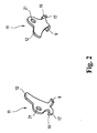
- the transmission member 11 shown perspectively in FIG. 2 from both sides also contains, in addition to the outwardly bent web 9, an inwardly projecting control element 17 which protrudes into a lateral recess 18 of the striking lever 6 shown in FIG. 1 and a rear oblique control surface 19 for engagement a control cam 20 on the hammer 6 contains.
- the control element 17 is designed as an inwardly bent tab of the transmission member 11 and has a roof or wedge-shaped cross-section.
- the provided with a hole 21 transmission member 11 is made in a suitable manner as a stamped and bent part made of sheet metal.
- the control cam 20 located above the recess 18 is designed so that it only comes into contact with its control surface 19 for rotation of the transmission member 11 when the trigger 1 is actuated. Otherwise, the control element 17 passes without touching the hammer 6 in the e.g. as a free cut recess 18, so that no initiated by the hammer 6 displacement of the fuse element 14 takes place in the upper release position.
- Figure 3 shows a non-tensioned starting position, in which the trigger 1 is in a non-actuated forward position and the hammer 6 is in a spaced from the firing pin 7 unstressed position.
- running as a safety slide fuse element 14 is pressed by the spring 13 in the lower securing position in which the not recognizable here lug 15 engages in the associated groove 16 of the firing pin 7 and prevents its axial movement.
- the running as a rotary lever transmission member 11 is acted upon by the spring 13 downwardly biased securing element 14 so that the outwardly bent nose 9 abuts the projection 8 of the trigger bar 3.
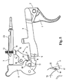
- FIG. 4 shows the fuse shortly before the triggering of a shot.
- the trigger 1 is in a take-off position, wherein the trigger rod 3 has been moved forward and at its rear end by a control slope 22 in conjunction with the same time serving as a control Schlaghebelachse 5 to release the hammer 5 also down.
- the transmission element 11 has been rotated counterclockwise via the nose 8 and the bent-over web 9 and thereby the securing element 14 is displaced upward into an intermediate position shown. Also in this intermediate position, the projection 15 of the securing element 14 still engages in the lateral groove 16 of the firing pin 7 and prevents its movement.
Landscapes
- Engineering & Computer Science (AREA)
- General Engineering & Computer Science (AREA)
- Automotive Seat Belt Assembly (AREA)
- Vehicle Cleaning, Maintenance, Repair, Refitting, And Outriggers (AREA)
- Acyclic And Carbocyclic Compounds In Medicinal Compositions (AREA)
- Fuses (AREA)
- Portable Nailing Machines And Staplers (AREA)
Description
- Die Erfindung betrifft eine Sicherung für eine Handfeuerwaffe nach dem Oberbegriff des Anspruchs 1.
- Eine derartige Sicherung ist aus der GB 660 046 A bekannt. Dort wird ein mit dem Schlagbolzen zusammenwirkendes Sicherungselement über einen um eine Achse drehbaren und mit der Abzugsstange gekoppelten Drehhebel als Übertragungsglied betätigt. Durch den Drehhebel wird die Bewegung der Abzugsstange so auf das Sicherungselement übertragen, dass das durch eine Feder in eine Sicherungsstellung beaufschlagte Sicherungselement bis zum Erreichen eines gewünschten Abzugspunktes und der dadurch bedingten Freigabe des Schlaghebels in eine Lösestellung bewegt wird.
- Wenn allerdings der Abzugsweg bei derartigen Sicherungssystemen verkürzt werden soll, ergibt sich die Problematik, dass die dann geringere Verschiebung der Abzugsstange nicht mehr ausreicht, um das Sicherungselement aus der vorgegebenen Sicherungsstellung in die Lösestellung zu bewegen. Der zwischen der Sicherungsstellung und der Lösestellung des Sicherungselements vorgesehene Weg darf nämlich nicht zu gering gewählt werden, da sonst die Sicherungsfunktion bereits durch kleinere Erschütterungen oder Stöße aufgehoben wird. Bei einer Erhöhung der das Sicherungselement in die Sicherungsstellung beaufschlagenden Feder würde wiederum das Abzugsgewicht erhöht, was sich nachteilig auf das Abzugsverhalten auswirken kann.
- Aufgabe der Erfindung ist es, eine Sicherung der eingangs genannten Art zu schaffen, die auch bei einem kleinen Abzugsweg und geringem Abzugsgewicht eine hohe Sicherheit gegen unerwünschtes Auslösen eines Schusses gewährleistet.
- Diese Aufgabe wird durch eine Sicherung mit den Merkmalen des Anspruchs 1 gelöst. Zweckmäßige Ausgestaltungen und vorteilhafte Weiterbildungen der Erfindung sind Gegenstand der Unteransprüche.
- Bei der erfindungsgemäßen Sicherung wird das Übertragungsglied zur Bewegung des Sicherungselements zunächst durch die Abzugsstange betätigt. Erst beim Erreichen einer vorgegebenen Abzugsstellung des Abzugs gelangt ein an dem Übertragungsglied vorgesehenes Steuerelement an dem Übertragungshebel in eine Stellung, in der es in Kontakt mit dem Schlaghebel gelangen kann und von diesen zur Bewegung des Sicherungselements in die Lösestellung betätigt wird. Die Bewegung des Sicherungselements in die Lösestellung muß nicht mehr vollständig durch die Abzugsstange erfolgen, wodurch der Abzugsweg verkürzt werden kann. Die Verbindung zwischen dem Übertragungsglied und dem Schlaghebel ist aber derart ausgelegt, dass die Bewegung des Übertragungsglieds durch den Schlagbolzen zur Lösen der Sicherung nur dann erfolgen kann, wenn sich der Abzugs in der gewünschten Abzugsstellung befindet. Dadurch wird die Sicherheit gegen ungewolltes Auslösen eines Schusses auch bei verkürztem Abzugsweg gewährleistet.
- In einer konstruktiv zweckmäßigen Ausführung greift das an dem Übertragungsglied vorgesehene Steuerelement bis zum Erreichen der vorgegebenen Abzugsstellung in eine seitliche Ausnehmung des Schlaghebels ein. Das Steuerelement enthält eine hintere Steuerfläche, die erst bei der vorgegebenen Abzugsstellung mit einer Steuerkurve des Schlaghebels in Kontakt gelangt, um die Bewegung des Sicherungselements in die Lösestellung durch den Schlaghebel zu erzeugen.
- Das Übertragungsglied ist in zweckmäßiger Weise als Drehhebel ausgeführt, der als Stanz-Biegeteil hergestellt werden kann. Das Steuerelement ist eine nach innen gebogene Lasche, an deren Rückseite die Steuerfläche für den Kontakt mit der Steuerkurve des Schlaghebels vorgesehen ist. Das Übertragungsglied mit dem Steuerelement kann aber auch aus dem Vollen gefertigt oder in anderer Weise ausgeführt sein.
- Weitere Besonderheiten und Vorzüge der Erfindung ergeben sich aus der folgenden Beschreibung eines bevorzugten Ausführungsbeispiels anhand der Zeichnung. Es zeigen:
- Figur 1
- eine Sicherung einer Handfeuerwaffe in einer schematischen Perspektive;
- Figur 2
- ein Übertragungsglied der in Figur 1 gezeigten Sicherung in zwei Perspektiven;
- Figur 3
- eine schematische Seitenansicht der in Figur 1 gezeigten Sicherung in einer Ausgangsstellung mit einer Detailansicht des Übertragungsglieds;
- Figur 4
- eine schematische Seitenansicht der in Figur 1 gezeigten Sicherung in einer Ausgangsstellung und
- Figur 5
- eine schematische Seitenansicht der in Figur 1 gezeigten Sicherung in einer Auslösestellung mit einer Detailansicht des Übertragungsglieds.
- Figur 1 zeigt einen Abzug 1, der in einem nicht dargestellten Griffstück, einer Einlage oder einem anderen geeigneten Teil einer Handfeuerwaffe um einen Abzugsbolzen 2 drehbar angeordnet ist. An einem oberhalb des Abzugsbolzens 2 liegenden Teil des Abzugs 1 ist das vordere Ende einer Abzugsstange 3 derart angelenkt, dass die Abzugsstange 3 bei der Betätigung des Abzugs 1 nach vorne bewegt wird. Im hinteren Bereich der Abzugsstange 3 ist an der Unterseite ein nach innen umgebogener Fortsatz 4 vorgesehen, der dazu dient, einen hier nicht dargestellten Auslösehebel zu betätigen. Durch den Auslösehebel wird der um eine Schlaghebelachse 5 drehbare und durch eine Schlaghebelfeder vorgespannte Schlaghebel 6 zum Aufschlagen auf einen Schlagbolzen 7 freigegeben. Diese Funktionsweise ist als solche bekannt, so dass auf die Darstellung des mit dem Fortsatz 4 zusammenwirkenden Auslösehebels sowie weiterer für die Beschreibung der Sicherung nicht erforderlichen Bauteile aus Gründen der Übersichtlichkeit verzichtet wurde.
- Im hinteren Bereich der Abzugsstange 3 ist an deren Oberseite eine nach oben vorstehende Nase 8 vorgesehen, die in Eingriff mit einem in Richtung der Abzugsstange 3 nach außen umgebogenen Steg 9 am unteren Ende eines um eine Querachse 10 drehbaren Übertragungsglieds 11 steht. Das obere Ende 12 des als Drehhebel ausgeführten Übertragungsglieds 11 steht in Kontakt mit einem durch eine Feder 13 nach unten beaufschlagten Sicherungselement 14, das einen in Richtung des Schlagbolzens 7 vorstehenden inneren Vorsprung 15 zum Eingriff in eine entsprechende seitliche Sicherungsnut 16 am Schlagbolzen 7 aufweist. Über das Übertragungsglied 11 ist das als Sicherungsschieber ausgeführte Sicherungselement 14 zwischen einer in Figur 1 gezeigten unteren Stellung, in welcher der Vorsprung 15 in die Sicherungsnut 16 eingreift und den Schlagbolzen 7 blockiert, und einer oberen Lösestellung, in welcher der Vorsprung 15 außer Eingriff mit der Sicherungsnut 16 gelangt und den Schlagbolzen 7 freigibt, verschiebbar.
- Das in Figur 2 von beiden Seiten perspektivisch dargestellte Übertragungsglied 11 enthält neben dem nach außen umgebogenen Steg 9 außerdem ein nach innen vorstehendes Steuerelement 17, das in eine in Figur 1 dargestellte seitliche Ausnehmung 18 des Schlaghebels 6 ragt und eine hintere schräge Steuerfläche 19 zum Eingriff mit einer Steuerkurve 20 am Schlaghebel 6 enthält. Bei der gezeigten Ausführung ist das Steuerelement 17 als nach innen umgebogene Lasche des Übertragungsglieds 11 ausgeführt und weist einen dach- oder keilförmigen Querschnitt auf. Das mit einem Loch 21 versehene Übertragungsglied 11 ist in zweckmäßiger Weise als Stanz-Biegeteil aus Blech hergestellt. Die oberhalb der Ausnehmung 18 befindliche Steuerkurve 20 ist derart ausgelegt, dass diese zur Drehung des Übertragungsglieds 11 nur dann mit dessen Steuerfläche 19 in Kontakt gelangt, wenn der Abzug 1 betätigt ist. Andernfalls gelangt das Steuerelement 17 ohne Berührung des Schlaghebels 6 in die z.B. als Freifräsung ausgeführte Ausnehmung 18, so dass keine durch den Schlaghebel 6 initiierte Verschiebung des Sicherungselements 14 in die obere Lösestellung erfolgt.
- Im Folgenden wird die Funktionsweise der Sicherung anhand der Figuren 3 bis 5 näher erläutert.
- Figur 3 zeigt eine nicht gespannte Ausgangslage, bei der sich der Abzug 1 in einer nicht betätigten vorderen Stellung und der Schlaghebel 6 in einer von dem Schlagbolzen 7 beabstandeten ungespannten Position befindet. In dieser Ausgangslage wird das als Sicherungsschieber ausgeführte Sicherungselement 14 von der Feder 13 in die untere Sicherungsstellung gedrückt, in welcher der hier nicht erkennbare Ansatz 15 in die zugehörige Nut 16 des Schlagbolzens 7 eingreift und dessen Axialbewegung verhindert. Das als Drehhebel ausgeführte Übertragungsglied 11 wird durch das über die Feder 13 nach unten vorgespannte Sicherungselement 14 so beaufschlagt, dass die nach außen umgebogene Nase 9 an dem Vorsprung 8 der Abzugsstange 3 anliegt. Wie besonders aus der vergrößerten Detailansicht in Figur 2 hervorgeht, greift der nach innen weisende Steueransatz 17 des Übertragungsglieds 11 in dieser Stellung ohne Berührung des Schlaghebels 6 in dessen Ausnehmung 18 derart ein, dass bei nicht betätigtem Abzug 1 sowohl in der gezeigten Position des Schlaghebels 6 als auch bei einem unbeabsichtigten Abschlagen und Auftreffen des Schlaghebels 6 auf den Schlagbolzen 7 keine Berührung zwischen dem Schlaghebel 6 und dem Übertragungsglied 11 und dadurch auch keine weitere Verschiebung des Sicherungselements 14 in die Lösestellung erfolgt. Das Sicherungselement 14 bleibt in der unteren Sicherungsstellung, so dass sich der Schlagbolzen 7 nicht bewegen und somit auch kein unbeabsichtigter Schuss lösen kann.
- Figur 4 zeigt die Sicherung kurz vor dem Auslösen eines Schusses. Der Abzug 1 befindet sich in einer Abzugsstellung, wobei die Abzugsstange 3 nach vorne und an ihrem hinteren Ende durch eine Steuerschräge 22 in Verbindung mit der gleichzeitig als Steuerelement dienenden Schlaghebelachse 5 zur Freigabe des Schlaghebels 5 auch nach unten bewegt wurde. Dabei wurde auch das Übertragungselement 11 über die Nase 8 und den nach vorne umgebogenen Steg 9 entgegen dem Uhrzeigersinn gedreht und dadurch das Sicherungselement 14 nach oben in eine gezeigte Zwischenstellung verschoben. Auch in dieser Zwischenstellung greift der Vorsprung 15 des Sicherungselements 14 noch in die seitliche Nut 16 des Schlagbolzens 7 ein und verhindert dessen Bewegung.
- Wenn in der Stellung von Figur 4 der Schlaghebel 6 freigegeben wird, gelangt die Steuerkurve 20 am Schlaghebel 6 kurz vor dessen Auftreffen auf den Schlagbolzen 7 in Kontakt mit der Steuerfläche 19 des Übertragungsglieds 11 und sorgt dafür, dass dieses weiter entgegen dem Uhrzeigersinn gedreht wird und dabei das als Steuerschieber ausgeführte Sicherungselement 14 in die in Figur 5 dargestellte obere Lösestellung verschiebt. In der oberen Lösestellung des Sicherungselements 14 befindet sich der hintere Ansatz 15 in einer längs verlaufenden Freifräsung 23 des Schlagbolzens 7, so dass die Sicherung des Schlagbolzens 7 aufgehoben ist. Die Bewegung des Sicherungselements 14 aus der noch verriegelten Zwischenstellung in die obere Lösestellung wird bei betätigtem Abzug 1 somit durch den Schlaghebel 6 initiiert.
Claims (9)
- Sicherung für eine Handfeuerwaffe mit einem Schlaghebel (6), einem Schlagbolzen (7), einem dem Schlagbolzen (7) zugeordneten Sicherungselement (14), einer durch einen Abzug (1) betätigbaren Abzugsstange (3) und einem mit der Abzugsstange (3) gekoppelten Übertragungsglied (11), durch welches das Sicherungselement (14) aus einer Sicherungsstellung zur Blockierung des Schlagbolzens (7) in eine Lösestellung zur Freigabe des Schlagbolzens (7) bewegbar ist, wobei das Übertragungsglied (11) ein Steuerelement (17) enthält, durch welches das Übertragungsglied (11) bei einer vorgegeben Abzugsstellung des Abzugs (1) zur Bewegung des Sicherungselements (14) in die Lösestellung betätigbar ist, dadurch gekennzeichnet, dass die Bewegung des Sicherungselements (14) aus einer noch verriegelten Zwischenstellung in eine obere Lösestellung bei betätigtem Abzug (1) durch den Schlaghebel (6) initiiert wird.
- Sicherung nach Anspruch 1, dadurch gekennzeichnet, dass das Steuerelement (17) bei nicht betätigtem Abzug (1) in eine Ausnehmung (18) des Schlaghebels (5) eingreift und eine Steuerfläche (19) aufweist, die bei der vorgegeben Abzugsstellung des Abzugs (1) zur Bewegung des Sicherungselements (14) in die Lösestellung mit einer Steuerkurve (20) des Schlaghebels (6) in Kontakt gelangt.
- Sicherung nach Anspruch 1 oder 2, dadurch gekennzeichnet, dass das Übertragungsglied (11) ein um eine Achse (10) drehbar angeordneter Drehhebel ist.
- Sicherung nach einem der Ansprüche 1 bis 3, dadurch gekennzeichnet, dass das Steuerelement (17) eine nach innen umgebogene Lasche ist, an deren Rückseite die Steuerfläche (19) vorgesehen ist.
- Sicherung nach einem der Ansprüche 1 bis 4, dadurch gekennzeichnet, dass das Sicherungselement (14) als Sicherungsschieber mit einem seitlichen Ansatz (15) zum Eingriff in eine entsprechende Sicherungsnut (16) des Schlagbolzens (7) ausgebildet ist.
- Sicherung nach Anspruch 5, dadurch gekennzeichnet, dass das Sicherungselement (14) verschiebbar ist zwischen einer unteren Sicherungsstellung, in welcher der Ansatz (15) in die Sicherungsnut (16) eingreift, und einer oberen Lösestellung, in der sich der Ansatz (15) in einer seitlichen Freifräsung (23) des Schlagbolzens (7) befindet.
- Sicherung nach Anspruch 5 oder 6, dadurch gekennzeichnet, dass das Sicherungselement (14) durch eine Feder (13) in die Sicherungsstellung beaufschlagt ist.
- Sicherung nach einem der Ansprüche 1 bis 7, dadurch gekennzeichnet, dass das Übertragungsglied (11) durch einen nach außen umgebogenen Steg (9) mit der Abzugsstange (3) gekoppelt ist.
- Sicherung nach einem der Ansprüche 1 bis 8, dadurch gekennzeichnet, dass die Abzugsstange (3) eine nach oben vorstehende Nase (8) zum Eingriff mit dem Übertragungsglied (11) enthält.
Priority Applications (4)
| Application Number | Priority Date | Filing Date | Title |
|---|---|---|---|
| EP04003783A EP1566606B1 (de) | 2004-02-19 | 2004-02-19 | Sicherung für eine Handfeuerwaffe |
| DE502004001472T DE502004001472D1 (de) | 2004-02-19 | 2004-02-19 | Sicherung für eine Handfeuerwaffe |
| AT04003783T ATE339666T1 (de) | 2004-02-19 | 2004-02-19 | Sicherung für eine handfeuerwaffe |
| US11/055,576 US7204051B2 (en) | 2004-02-19 | 2005-02-09 | Safety for a hand firearm |
Applications Claiming Priority (1)
| Application Number | Priority Date | Filing Date | Title |
|---|---|---|---|
| EP04003783A EP1566606B1 (de) | 2004-02-19 | 2004-02-19 | Sicherung für eine Handfeuerwaffe |
Publications (2)
| Publication Number | Publication Date |
|---|---|
| EP1566606A1 EP1566606A1 (de) | 2005-08-24 |
| EP1566606B1 true EP1566606B1 (de) | 2006-09-13 |
Family
ID=34707323
Family Applications (1)
| Application Number | Title | Priority Date | Filing Date |
|---|---|---|---|
| EP04003783A Expired - Lifetime EP1566606B1 (de) | 2004-02-19 | 2004-02-19 | Sicherung für eine Handfeuerwaffe |
Country Status (4)
| Country | Link |
|---|---|
| US (1) | US7204051B2 (de) |
| EP (1) | EP1566606B1 (de) |
| AT (1) | ATE339666T1 (de) |
| DE (1) | DE502004001472D1 (de) |
Families Citing this family (29)
| Publication number | Priority date | Publication date | Assignee | Title |
|---|---|---|---|---|
| US7703230B2 (en) * | 2004-12-22 | 2010-04-27 | Smith & Wesson Corp. | Positive striker lock safety for use with a firearm |
| US8276302B2 (en) * | 2008-12-30 | 2012-10-02 | Smith & Wesson Corp. | Manual slide and hammer lock safety for a firearm |
| US8549782B2 (en) | 2008-12-31 | 2013-10-08 | Smith & Wesson Corp. | Firearm having an indexing mechanism |
| WO2010145671A1 (de) * | 2009-06-15 | 2010-12-23 | Armatix Invest Gmbh | Schusswaffensicherung |
| AT508016B1 (de) * | 2009-06-30 | 2010-10-15 | Steyr Mannlicher Holding Gmbh | Spann- und entspannvorrichtung für eine schusswaffe |
| ITBS20100089A1 (it) * | 2010-04-22 | 2011-10-23 | Beretta Armi Spa | Dispositivo di sicurezza automatico per arma da fuoco, in particolare per pistola |
| US8464455B2 (en) * | 2011-01-07 | 2013-06-18 | Sturm, Ruger & Company, Inc. | Lockable safety for firearm |
| US8438768B2 (en) | 2011-01-07 | 2013-05-14 | Sturm, Ruger & Company, Inc. | Magazine disconnect mechanism for firearm |
| US8443537B2 (en) * | 2011-09-23 | 2013-05-21 | Smith & Wesson Corp. | Drop safety for a firing pin of a firearm |
| UA108923C2 (xx) * | 2013-08-27 | 2015-06-25 | Спусковий механізм пістолета | |
| UA108924C2 (xx) | 2013-08-27 | 2015-06-25 | Стріляючий ударниковий механізм пістолета | |
| DE102013022082B3 (de) * | 2013-12-23 | 2014-10-16 | Heckler & Koch Gmbh | Fallsicherung einer hahnlosen Selbstladepistole und Selbstladepistole mit einer solchen Fallsicherung |
| US9810496B2 (en) | 2014-05-15 | 2017-11-07 | Savage Arms, Inc. | Semiautomatic firearm |
| CZ306583B6 (cs) * | 2015-11-11 | 2017-03-15 | Česká Zbrojovka A.S. | Úderníkové ústrojí pro automatické a poloautomatické pistole |
| US10330413B2 (en) | 2016-08-11 | 2019-06-25 | Springfield, Inc. | Half-cock trigger safety assembly |
| US9927197B1 (en) * | 2016-09-28 | 2018-03-27 | WHG Properties, LLC | Trigger mechanism for a firearm |
| USD828895S1 (en) | 2016-09-28 | 2018-09-18 | WHG Properties, LLC | Trigger mechanism |
| US9841249B1 (en) * | 2016-09-30 | 2017-12-12 | Ignis Kinetics, Inc. | Firearm safety device and system for uniquely and individually enabling firearm discharge |
| US10175019B1 (en) | 2017-07-10 | 2019-01-08 | Mohamed Al-Mutawa | Trigger mechanism for hammer fired-firearm |
| US12480740B2 (en) | 2017-12-27 | 2025-11-25 | Magpul Industries Corp. | Two-part folding trigger for a folding firearm |
| US10443971B2 (en) | 2017-12-27 | 2019-10-15 | Magpul Industries Corp. | Foldable firearm |
| US10823517B1 (en) * | 2019-05-28 | 2020-11-03 | 17 Design and Manufacturing, LLC | Universal handgun slide |
| EP3800430B1 (de) * | 2019-10-04 | 2023-06-07 | Glock Technology GmbH | Feuerwaffe |
| US11428484B2 (en) * | 2020-01-17 | 2022-08-30 | Blackpowder Products, Inc. | Firearm |
| US11578939B2 (en) | 2020-02-12 | 2023-02-14 | Sturm, Ruger & Company, Inc. | Safety mechanism for firearms |
| US20250180333A1 (en) * | 2020-02-18 | 2025-06-05 | Langdon Tactical Technology Inc. | Methods and apparatus for optical adapter for firearm slide |
| USD1069016S1 (en) | 2021-06-02 | 2025-04-01 | Magpul Industries Corp. | Folding gun |
| USD1085314S1 (en) | 2021-12-20 | 2025-07-22 | Magpul Industries Corp. | Folding gun |
| TR2023001948A2 (tr) | 2022-02-22 | 2023-09-21 | Hs Produkt D O O | Manüel başparmak emni̇yeti̇ |
Family Cites Families (20)
| Publication number | Priority date | Publication date | Assignee | Title |
|---|---|---|---|---|
| BE487011A (de) * | 1948-01-28 | |||
| CH338381A (de) * | 1955-03-30 | 1959-05-15 | Metallgesellschaft Etablisseme | Schlagbolzenverriegelung an einer Handfeuerwaffe |
| CH528057A (de) * | 1970-08-24 | 1972-09-15 | Sig Schweiz Industrieges | Sicherungsvorrichtung für den Schlagbolzen von Handfeuerwaffen |
| DE2212211C3 (de) * | 1972-03-14 | 1978-08-10 | Fa. Carl Walther, 7900 Ulm | Schlagbolzensicherungseinrichtung für Handfeuerwaffen |
| US4021955A (en) * | 1976-05-03 | 1977-05-10 | Colt Industries Operating Corporation (Firearms Division) | Firing pin locking device and method |
| IT1209739B (it) * | 1980-04-16 | 1989-08-30 | Beretta Armi Spa | Dispositivo di comando della sicura automatica sul percussore di pistole. |
| US4555861A (en) * | 1983-12-16 | 1985-12-03 | Colt Industries Operating Corp | Firing pin locking device |
| US4843748A (en) * | 1988-08-24 | 1989-07-04 | Itm Industrial Technology & Machines Ag | Firearm |
| US5245776A (en) * | 1990-06-12 | 1993-09-21 | Richard A. Voit | Firearm having improved safety and accuracy features |
| US5157209A (en) * | 1991-12-23 | 1992-10-20 | Dunn Peter B | Semi-automatic safety handgun |
| US5493806A (en) * | 1994-09-21 | 1996-02-27 | Colt's Manufacturing Company Inc. | Striker retaining system for a firearm |
| US6460282B1 (en) * | 1998-03-17 | 2002-10-08 | Alfredo A. Bustos | Hammer mechanism for firearms |
| US6256918B1 (en) * | 1998-11-19 | 2001-07-10 | Atilla Szabo | Firing pin locking assembly for a semi-automatic handgun |
| US6647655B2 (en) * | 2000-04-19 | 2003-11-18 | Alfred W. Salvitti | Model 1911 type firearm safety lock |
| US6374526B1 (en) * | 2000-05-18 | 2002-04-23 | Smith & Wesson Corp. | Firing pin block for pistol |
| US6510641B1 (en) * | 2000-09-15 | 2003-01-28 | Arthur Viani | Trigger and firing pin locking system |
| US6470615B1 (en) * | 2000-10-30 | 2002-10-29 | William H. Peterken | Visible firearm safety and dry-fire device |
| ATE289674T1 (de) * | 2001-07-31 | 2005-03-15 | Sat Swiss Arms Technology Ag | Automatische innere zündstiftsicherung für pistolen |
| US6588136B2 (en) * | 2001-10-11 | 2003-07-08 | Fn Mfg Llc | Decocking lever |
| US6941692B1 (en) * | 2002-06-13 | 2005-09-13 | Alvern J. Krinke | Firearm safety mechanism |
-
2004
- 2004-02-19 EP EP04003783A patent/EP1566606B1/de not_active Expired - Lifetime
- 2004-02-19 DE DE502004001472T patent/DE502004001472D1/de not_active Expired - Lifetime
- 2004-02-19 AT AT04003783T patent/ATE339666T1/de not_active IP Right Cessation
-
2005
- 2005-02-09 US US11/055,576 patent/US7204051B2/en not_active Expired - Lifetime
Also Published As
| Publication number | Publication date |
|---|---|
| US20060048428A1 (en) | 2006-03-09 |
| US7204051B2 (en) | 2007-04-17 |
| ATE339666T1 (de) | 2006-10-15 |
| DE502004001472D1 (de) | 2006-10-26 |
| EP1566606A1 (de) | 2005-08-24 |
Similar Documents
| Publication | Publication Date | Title |
|---|---|---|
| EP1566606A1 (de) | Sicherung für eine Handfeuerwaffe | |
| EP2205924B1 (de) | Fanghebel, abzugseinrichtung und griffstück für eine waffe | |
| EP0408865A2 (de) | Ventilpistole, insbesondere fÀ¼r ein Hochdruckreinigungsgerät | |
| CH631573A5 (de) | Ueberstromschutzschalter mit ein- und ausschaltwippe. | |
| EP1735203B1 (de) | Feststelleinrichtung einer zumindest höhenverstellbaren lenksäule | |
| EP1878992B1 (de) | Abzugseinrichtung für Handfeuerwaffen | |
| DE2812759B2 (de) | Abzugsvorrichtung für einen Revolver | |
| DE102004041054B3 (de) | Schlosssystem für eine mehrläufige Waffe | |
| DE3235918C2 (de) | ||
| CH687418A5 (de) | Abzugsvorrichtung fuer ein Gewehr. | |
| DE2855224C2 (de) | Schlagbolzensicherung für Handfeuerwaffen, insbesondere Selbstladepistolen | |
| EP2068110B1 (de) | Schlosssystem für eine mehrläufige Waffe | |
| EP2228616B1 (de) | Abzugsmechanismus für Handfeuerwaffen | |
| EP1669712B1 (de) | Abzugseinrichtung für eine Handfeuerwaffe | |
| EP0666391B1 (de) | Kraftfahrzeug-Türschloss und Verfahren zu Einbau eines Kraftfahrzeug-Türschlosses | |
| EP1643203B1 (de) | Abzugsystem für Handfeuerwaffen | |
| EP1620619B1 (de) | Kraftfahrzeugtürverschluss | |
| DE2204438C3 (de) | Piezoelektrische Zündvorrichtung | |
| DE3342783C2 (de) | Sicherheitsgurtverschluss mit drehbarer Sperrklinke | |
| DE3640606C1 (en) | Breech action (bolt) for rifles | |
| DE10307222B3 (de) | Abzugssystem für Handfeuerwaffen | |
| EP0603455A2 (de) | Doppler-Stangensicherung bei mehrläufigen Gewehren | |
| WO1997047940A1 (de) | Sicherung für gewehre mit zylinderverschluss | |
| AT409548B (de) | Repetierbüchse | |
| EP1821059B1 (de) | Abzugsvorrichtung für eine Handfeuerwaffe |
Legal Events
| Date | Code | Title | Description |
|---|---|---|---|
| PUAI | Public reference made under article 153(3) epc to a published international application that has entered the european phase |
Free format text: ORIGINAL CODE: 0009012 |
|
| AK | Designated contracting states |
Kind code of ref document: A1 Designated state(s): AT BE BG CH CY CZ DE DK EE ES FI FR GB GR HU IE IT LI LU MC NL PT RO SE SI SK TR |
|
| AX | Request for extension of the european patent |
Extension state: AL LT LV MK |
|
| 17P | Request for examination filed |
Effective date: 20060224 |
|
| GRAP | Despatch of communication of intention to grant a patent |
Free format text: ORIGINAL CODE: EPIDOSNIGR1 |
|
| AKX | Designation fees paid |
Designated state(s): AT BE BG CH CY CZ DE DK EE ES FI FR GB GR HU IE IT LI LU MC NL PT RO SE SI SK TR |
|
| GRAS | Grant fee paid |
Free format text: ORIGINAL CODE: EPIDOSNIGR3 |
|
| GRAA | (expected) grant |
Free format text: ORIGINAL CODE: 0009210 |
|
| AK | Designated contracting states |
Kind code of ref document: B1 Designated state(s): AT BE BG CH CY CZ DE DK EE ES FI FR GB GR HU IE IT LI LU MC NL PT RO SE SI SK TR |
|
| PG25 | Lapsed in a contracting state [announced via postgrant information from national office to epo] |
Ref country code: NL Free format text: LAPSE BECAUSE OF FAILURE TO SUBMIT A TRANSLATION OF THE DESCRIPTION OR TO PAY THE FEE WITHIN THE PRESCRIBED TIME-LIMIT Effective date: 20060913 Ref country code: IT Free format text: LAPSE BECAUSE OF FAILURE TO SUBMIT A TRANSLATION OF THE DESCRIPTION OR TO PAY THE FEE WITHIN THE PRESCRIBED TIME-LIMIT;WARNING: LAPSES OF ITALIAN PATENTS WITH EFFECTIVE DATE BEFORE 2007 MAY HAVE OCCURRED AT ANY TIME BEFORE 2007. THE CORRECT EFFECTIVE DATE MAY BE DIFFERENT FROM THE ONE RECORDED. Effective date: 20060913 Ref country code: RO Free format text: LAPSE BECAUSE OF FAILURE TO SUBMIT A TRANSLATION OF THE DESCRIPTION OR TO PAY THE FEE WITHIN THE PRESCRIBED TIME-LIMIT Effective date: 20060913 Ref country code: SI Free format text: LAPSE BECAUSE OF FAILURE TO SUBMIT A TRANSLATION OF THE DESCRIPTION OR TO PAY THE FEE WITHIN THE PRESCRIBED TIME-LIMIT Effective date: 20060913 Ref country code: SK Free format text: LAPSE BECAUSE OF FAILURE TO SUBMIT A TRANSLATION OF THE DESCRIPTION OR TO PAY THE FEE WITHIN THE PRESCRIBED TIME-LIMIT Effective date: 20060913 Ref country code: FI Free format text: LAPSE BECAUSE OF FAILURE TO SUBMIT A TRANSLATION OF THE DESCRIPTION OR TO PAY THE FEE WITHIN THE PRESCRIBED TIME-LIMIT Effective date: 20060913 Ref country code: IE Free format text: LAPSE BECAUSE OF FAILURE TO SUBMIT A TRANSLATION OF THE DESCRIPTION OR TO PAY THE FEE WITHIN THE PRESCRIBED TIME-LIMIT Effective date: 20060913 Ref country code: GB Free format text: LAPSE BECAUSE OF FAILURE TO SUBMIT A TRANSLATION OF THE DESCRIPTION OR TO PAY THE FEE WITHIN THE PRESCRIBED TIME-LIMIT Effective date: 20060913 |
|
| REG | Reference to a national code |
Ref country code: GB Ref legal event code: FG4D Free format text: NOT ENGLISH |
|
| REG | Reference to a national code |
Ref country code: CH Ref legal event code: EP |
|
| REG | Reference to a national code |
Ref country code: CH Ref legal event code: NV Representative=s name: LUCHS & PARTNER PATENTANWAELTE |
|
| REG | Reference to a national code |
Ref country code: IE Ref legal event code: FG4D Free format text: LANGUAGE OF EP DOCUMENT: GERMAN |
|
| REF | Corresponds to: |
Ref document number: 502004001472 Country of ref document: DE Date of ref document: 20061026 Kind code of ref document: P |
|
| PG25 | Lapsed in a contracting state [announced via postgrant information from national office to epo] |
Ref country code: DK Free format text: LAPSE BECAUSE OF FAILURE TO SUBMIT A TRANSLATION OF THE DESCRIPTION OR TO PAY THE FEE WITHIN THE PRESCRIBED TIME-LIMIT Effective date: 20061213 Ref country code: BG Free format text: LAPSE BECAUSE OF FAILURE TO SUBMIT A TRANSLATION OF THE DESCRIPTION OR TO PAY THE FEE WITHIN THE PRESCRIBED TIME-LIMIT Effective date: 20061213 Ref country code: SE Free format text: LAPSE BECAUSE OF FAILURE TO SUBMIT A TRANSLATION OF THE DESCRIPTION OR TO PAY THE FEE WITHIN THE PRESCRIBED TIME-LIMIT Effective date: 20061213 |
|
| PG25 | Lapsed in a contracting state [announced via postgrant information from national office to epo] |
Ref country code: ES Free format text: LAPSE BECAUSE OF FAILURE TO SUBMIT A TRANSLATION OF THE DESCRIPTION OR TO PAY THE FEE WITHIN THE PRESCRIBED TIME-LIMIT Effective date: 20061224 |
|
| PG25 | Lapsed in a contracting state [announced via postgrant information from national office to epo] |
Ref country code: PT Free format text: LAPSE BECAUSE OF FAILURE TO SUBMIT A TRANSLATION OF THE DESCRIPTION OR TO PAY THE FEE WITHIN THE PRESCRIBED TIME-LIMIT Effective date: 20070226 |
|
| PG25 | Lapsed in a contracting state [announced via postgrant information from national office to epo] |
Ref country code: MC Free format text: LAPSE BECAUSE OF NON-PAYMENT OF DUE FEES Effective date: 20070228 |
|
| NLV1 | Nl: lapsed or annulled due to failure to fulfill the requirements of art. 29p and 29m of the patents act | ||
| ET | Fr: translation filed | ||
| GBV | Gb: ep patent (uk) treated as always having been void in accordance with gb section 77(7)/1977 [no translation filed] |
Effective date: 20060913 |
|
| REG | Reference to a national code |
Ref country code: IE Ref legal event code: FD4D |
|
| PLBE | No opposition filed within time limit |
Free format text: ORIGINAL CODE: 0009261 |
|
| STAA | Information on the status of an ep patent application or granted ep patent |
Free format text: STATUS: NO OPPOSITION FILED WITHIN TIME LIMIT |
|
| 26N | No opposition filed |
Effective date: 20070614 |
|
| PGFP | Annual fee paid to national office [announced via postgrant information from national office to epo] |
Ref country code: CZ Payment date: 20071126 Year of fee payment: 5 |
|
| PG25 | Lapsed in a contracting state [announced via postgrant information from national office to epo] |
Ref country code: GR Free format text: LAPSE BECAUSE OF FAILURE TO SUBMIT A TRANSLATION OF THE DESCRIPTION OR TO PAY THE FEE WITHIN THE PRESCRIBED TIME-LIMIT Effective date: 20061214 |
|
| PGFP | Annual fee paid to national office [announced via postgrant information from national office to epo] |
Ref country code: CH Payment date: 20080319 Year of fee payment: 5 |
|
| PGFP | Annual fee paid to national office [announced via postgrant information from national office to epo] |
Ref country code: AT Payment date: 20080220 Year of fee payment: 5 |
|
| PG25 | Lapsed in a contracting state [announced via postgrant information from national office to epo] |
Ref country code: EE Free format text: LAPSE BECAUSE OF FAILURE TO SUBMIT A TRANSLATION OF THE DESCRIPTION OR TO PAY THE FEE WITHIN THE PRESCRIBED TIME-LIMIT Effective date: 20060913 |
|
| PGFP | Annual fee paid to national office [announced via postgrant information from national office to epo] |
Ref country code: FR Payment date: 20080111 Year of fee payment: 5 |
|
| PGFP | Annual fee paid to national office [announced via postgrant information from national office to epo] |
Ref country code: BE Payment date: 20080110 Year of fee payment: 5 |
|
| PGFP | Annual fee paid to national office [announced via postgrant information from national office to epo] |
Ref country code: TR Payment date: 20080128 Year of fee payment: 5 |
|
| BERE | Be: lapsed |
Owner name: SWISS ARMS TECHNOLOGY A.G. *SAT Effective date: 20090228 |
|
| PG25 | Lapsed in a contracting state [announced via postgrant information from national office to epo] |
Ref country code: LU Free format text: LAPSE BECAUSE OF NON-PAYMENT OF DUE FEES Effective date: 20070219 Ref country code: CY Free format text: LAPSE BECAUSE OF FAILURE TO SUBMIT A TRANSLATION OF THE DESCRIPTION OR TO PAY THE FEE WITHIN THE PRESCRIBED TIME-LIMIT Effective date: 20060913 |
|
| PGFP | Annual fee paid to national office [announced via postgrant information from national office to epo] |
Ref country code: IT Payment date: 20090225 Year of fee payment: 6 |
|
| PG25 | Lapsed in a contracting state [announced via postgrant information from national office to epo] |
Ref country code: HU Free format text: LAPSE BECAUSE OF FAILURE TO SUBMIT A TRANSLATION OF THE DESCRIPTION OR TO PAY THE FEE WITHIN THE PRESCRIBED TIME-LIMIT Effective date: 20070314 |
|
| REG | Reference to a national code |
Ref country code: CH Ref legal event code: PL |
|
| PG25 | Lapsed in a contracting state [announced via postgrant information from national office to epo] |
Ref country code: CZ Free format text: LAPSE BECAUSE OF NON-PAYMENT OF DUE FEES Effective date: 20090219 Ref country code: CH Free format text: LAPSE BECAUSE OF NON-PAYMENT OF DUE FEES Effective date: 20090228 Ref country code: LI Free format text: LAPSE BECAUSE OF NON-PAYMENT OF DUE FEES Effective date: 20090228 Ref country code: AT Free format text: LAPSE BECAUSE OF NON-PAYMENT OF DUE FEES Effective date: 20090219 |
|
| REG | Reference to a national code |
Ref country code: FR Ref legal event code: ST Effective date: 20091030 |
|
| PG25 | Lapsed in a contracting state [announced via postgrant information from national office to epo] |
Ref country code: BE Free format text: LAPSE BECAUSE OF NON-PAYMENT OF DUE FEES Effective date: 20090228 |
|
| PG25 | Lapsed in a contracting state [announced via postgrant information from national office to epo] |
Ref country code: FR Free format text: LAPSE BECAUSE OF NON-PAYMENT OF DUE FEES Effective date: 20090302 |
|
| PG25 | Lapsed in a contracting state [announced via postgrant information from national office to epo] |
Ref country code: TR Free format text: LAPSE BECAUSE OF NON-PAYMENT OF DUE FEES Effective date: 20090219 |
|
| PG25 | Lapsed in a contracting state [announced via postgrant information from national office to epo] |
Ref country code: IT Free format text: LAPSE BECAUSE OF NON-PAYMENT OF DUE FEES Effective date: 20100219 |
|
| PG25 | Lapsed in a contracting state [announced via postgrant information from national office to epo] |
Ref country code: IT Free format text: LAPSE BECAUSE OF NON-PAYMENT OF DUE FEES Effective date: 20080219 |
|
| PGFP | Annual fee paid to national office [announced via postgrant information from national office to epo] |
Ref country code: DE Payment date: 20200403 Year of fee payment: 17 |
|
| REG | Reference to a national code |
Ref country code: DE Ref legal event code: R119 Ref document number: 502004001472 Country of ref document: DE |
|
| PG25 | Lapsed in a contracting state [announced via postgrant information from national office to epo] |
Ref country code: DE Free format text: LAPSE BECAUSE OF NON-PAYMENT OF DUE FEES Effective date: 20210901 |