EP1566533B1 - Cylinder intake air quantity calculation device - Google Patents
Cylinder intake air quantity calculation device Download PDFInfo
- Publication number
- EP1566533B1 EP1566533B1 EP05002174A EP05002174A EP1566533B1 EP 1566533 B1 EP1566533 B1 EP 1566533B1 EP 05002174 A EP05002174 A EP 05002174A EP 05002174 A EP05002174 A EP 05002174A EP 1566533 B1 EP1566533 B1 EP 1566533B1
- Authority
- EP
- European Patent Office
- Prior art keywords
- cylinder
- air quantity
- intake air
- manifold
- internal pressure
- Prior art date
- Legal status (The legal status is an assumption and is not a legal conclusion. Google has not performed a legal analysis and makes no representation as to the accuracy of the status listed.)
- Expired - Fee Related
Links
Images


Classifications
-
- B—PERFORMING OPERATIONS; TRANSPORTING
- B05—SPRAYING OR ATOMISING IN GENERAL; APPLYING FLUENT MATERIALS TO SURFACES, IN GENERAL
- B05B—SPRAYING APPARATUS; ATOMISING APPARATUS; NOZZLES
- B05B7/00—Spraying apparatus for discharge of liquids or other fluent materials from two or more sources, e.g. of liquid and air, of powder and gas
- B05B7/02—Spray pistols; Apparatus for discharge
-
- F—MECHANICAL ENGINEERING; LIGHTING; HEATING; WEAPONS; BLASTING
- F02—COMBUSTION ENGINES; HOT-GAS OR COMBUSTION-PRODUCT ENGINE PLANTS
- F02D—CONTROLLING COMBUSTION ENGINES
- F02D35/00—Controlling engines, dependent on conditions exterior or interior to engines, not otherwise provided for
- F02D35/02—Controlling engines, dependent on conditions exterior or interior to engines, not otherwise provided for on interior conditions
- F02D35/023—Controlling engines, dependent on conditions exterior or interior to engines, not otherwise provided for on interior conditions by determining the cylinder pressure
- F02D35/024—Controlling engines, dependent on conditions exterior or interior to engines, not otherwise provided for on interior conditions by determining the cylinder pressure using an estimation
-
- F—MECHANICAL ENGINEERING; LIGHTING; HEATING; WEAPONS; BLASTING
- F02—COMBUSTION ENGINES; HOT-GAS OR COMBUSTION-PRODUCT ENGINE PLANTS
- F02D—CONTROLLING COMBUSTION ENGINES
- F02D41/00—Electrical control of supply of combustible mixture or its constituents
- F02D41/02—Circuit arrangements for generating control signals
- F02D41/14—Introducing closed-loop corrections
- F02D41/1401—Introducing closed-loop corrections characterised by the control or regulation method
- F02D41/1406—Introducing closed-loop corrections characterised by the control or regulation method with use of a optimisation method, e.g. iteration
-
- F—MECHANICAL ENGINEERING; LIGHTING; HEATING; WEAPONS; BLASTING
- F02—COMBUSTION ENGINES; HOT-GAS OR COMBUSTION-PRODUCT ENGINE PLANTS
- F02D—CONTROLLING COMBUSTION ENGINES
- F02D41/00—Electrical control of supply of combustible mixture or its constituents
- F02D41/02—Circuit arrangements for generating control signals
- F02D41/14—Introducing closed-loop corrections
- F02D41/1438—Introducing closed-loop corrections using means for determining characteristics of the combustion gases; Sensors therefor
- F02D41/1444—Introducing closed-loop corrections using means for determining characteristics of the combustion gases; Sensors therefor characterised by the characteristics of the combustion gases
- F02D41/1448—Introducing closed-loop corrections using means for determining characteristics of the combustion gases; Sensors therefor characterised by the characteristics of the combustion gases the characteristics being an exhaust gas pressure
-
- F—MECHANICAL ENGINEERING; LIGHTING; HEATING; WEAPONS; BLASTING
- F02—COMBUSTION ENGINES; HOT-GAS OR COMBUSTION-PRODUCT ENGINE PLANTS
- F02D—CONTROLLING COMBUSTION ENGINES
- F02D41/00—Electrical control of supply of combustible mixture or its constituents
- F02D41/02—Circuit arrangements for generating control signals
- F02D41/18—Circuit arrangements for generating control signals by measuring intake air flow
- F02D41/182—Circuit arrangements for generating control signals by measuring intake air flow for the control of a fuel injection device
-
- F—MECHANICAL ENGINEERING; LIGHTING; HEATING; WEAPONS; BLASTING
- F02—COMBUSTION ENGINES; HOT-GAS OR COMBUSTION-PRODUCT ENGINE PLANTS
- F02D—CONTROLLING COMBUSTION ENGINES
- F02D41/00—Electrical control of supply of combustible mixture or its constituents
- F02D41/02—Circuit arrangements for generating control signals
- F02D41/18—Circuit arrangements for generating control signals by measuring intake air flow
- F02D41/187—Circuit arrangements for generating control signals by measuring intake air flow using a hot wire flow sensor
-
- F—MECHANICAL ENGINEERING; LIGHTING; HEATING; WEAPONS; BLASTING
- F16—ENGINEERING ELEMENTS AND UNITS; GENERAL MEASURES FOR PRODUCING AND MAINTAINING EFFECTIVE FUNCTIONING OF MACHINES OR INSTALLATIONS; THERMAL INSULATION IN GENERAL
- F16N—LUBRICATING
- F16N7/00—Arrangements for supplying oil or unspecified lubricant from a stationary reservoir or the equivalent in or on the machine or member to be lubricated
- F16N7/30—Arrangements for supplying oil or unspecified lubricant from a stationary reservoir or the equivalent in or on the machine or member to be lubricated the oil being fed or carried along by another fluid
- F16N7/32—Mist lubrication
- F16N7/34—Atomising devices for oil
-
- F—MECHANICAL ENGINEERING; LIGHTING; HEATING; WEAPONS; BLASTING
- F02—COMBUSTION ENGINES; HOT-GAS OR COMBUSTION-PRODUCT ENGINE PLANTS
- F02D—CONTROLLING COMBUSTION ENGINES
- F02D2200/00—Input parameters for engine control
- F02D2200/02—Input parameters for engine control the parameters being related to the engine
- F02D2200/04—Engine intake system parameters
- F02D2200/0402—Engine intake system parameters the parameter being determined by using a model of the engine intake or its components
-
- F—MECHANICAL ENGINEERING; LIGHTING; HEATING; WEAPONS; BLASTING
- F02—COMBUSTION ENGINES; HOT-GAS OR COMBUSTION-PRODUCT ENGINE PLANTS
- F02D—CONTROLLING COMBUSTION ENGINES
- F02D2200/00—Input parameters for engine control
- F02D2200/02—Input parameters for engine control the parameters being related to the engine
- F02D2200/04—Engine intake system parameters
- F02D2200/0406—Intake manifold pressure
- F02D2200/0408—Estimation of intake manifold pressure
-
- F—MECHANICAL ENGINEERING; LIGHTING; HEATING; WEAPONS; BLASTING
- F02—COMBUSTION ENGINES; HOT-GAS OR COMBUSTION-PRODUCT ENGINE PLANTS
- F02D—CONTROLLING COMBUSTION ENGINES
- F02D2200/00—Input parameters for engine control
- F02D2200/02—Input parameters for engine control the parameters being related to the engine
- F02D2200/04—Engine intake system parameters
- F02D2200/0414—Air temperature
-
- F—MECHANICAL ENGINEERING; LIGHTING; HEATING; WEAPONS; BLASTING
- F02—COMBUSTION ENGINES; HOT-GAS OR COMBUSTION-PRODUCT ENGINE PLANTS
- F02D—CONTROLLING COMBUSTION ENGINES
- F02D41/00—Electrical control of supply of combustible mixture or its constituents
- F02D41/02—Circuit arrangements for generating control signals
- F02D41/14—Introducing closed-loop corrections
- F02D41/1438—Introducing closed-loop corrections using means for determining characteristics of the combustion gases; Sensors therefor
- F02D41/1444—Introducing closed-loop corrections using means for determining characteristics of the combustion gases; Sensors therefor characterised by the characteristics of the combustion gases
- F02D41/1446—Introducing closed-loop corrections using means for determining characteristics of the combustion gases; Sensors therefor characterised by the characteristics of the combustion gases the characteristics being exhaust temperatures
Definitions
- the present invention generally relates to a cylinder intake air quantity determination device for an internal combustion engine. More specifically, the present invention relates to a cylinder intake air quantity determination device that is configured and arranged to calculate a cylinder intake air quantity with good precision based on a manifold internal pressure and a cylinder internal pressure.
- Japanese Laid-Open Patent Publication No. 2001-50091 discloses a cylinder intake air quantity determination device for a variable valve timing control internal combustion engine.
- the cylinder intake air quantity determination device disclosed in this reference is configured to calculate an amount of air inside an intake manifold by computing a balance between an amount of air flowing into the intake manifold and an amount of air flowing out of the intake manifold which corresponds to a cylinder intake air quantity flowing from the manifold to the cylinder computed in a previous control routine. Then, the cylinder intake air quantity determination device of this reference is configured to compute a current cylinder intake air quantity based on the amount of air inside the manifold and a cylinder volume that is corrected based on a volume of the cylinder when an intake valve is closed.
- Japanese Laid-Open Patent Publication No. 2002-371894 discloses another example of a cylinder intake air quantity determination device for an internal combustion engine.
- a mass air quantity inside an intake manifold is calculated by computing a balance between an amount of air flowing into the intake manifold and an amount of air flowing out of the intake manifold. Then, a cylinder intake mass air quantity flowing into a cylinder is calculated.
- the mass air quantity inside the intake manifold is corrected to remove a superfluous air amount to obtain a mass air quantity inside the intake manifold when the engine is stopped. Then, this corrected mass air quantity inside the intake manifold is used to calculate an initial value for a mass air quantity inside the intake manifold when the engine is restarted.
- the cylinder intake air quantity is calculated by assuming the cylinder pressure is a constant value.
- a pressure inside the intake manifold varies during low valve lift operation, during advanced or delayed valve closing timing operation. In such cases, there may be errors in the calculation results for the cylinder intake air quantity.
- a cylinder intake air quantity determination device that basically comprises a manifold internal air quantity calculation section, a manifold internal pressure calculation section, a cylinder internal pressure calculation section and a cylinder intake air quantity calculation section.
- the manifold internal air quantity calculation section is configured to calculate a manifold internal air quantity based on a balance between an air quantity flowing into an intake manifold and an air quantity flowing out of the intake manifold.
- the manifold internal pressure calculation section is configured to calculate a manifold internal pressure based at least on the manifold internal air quantity.
- the cylinder internal pressure calculation section is configured to calculate a cylinder internal pressure based on at least one parameter that affects a vapor state inside a cylinder.
- the cylinder intake air quantity calculation section is configured to calculate a cylinder intake air quantity based on the manifold internal pressure and the cylinder internal pressure.
- Figure 1 is a schematic diagram of an internal combustion engine with a cylinder intake air quantity determination device in accordance with a preferred embodiment of the present invention
- Figure 2 is a control block diagram for calculating a cylinder intake air quantity in the cylinder intake air quantity determination device in accordance with the preferred embodiment of the present invention
- Figure 3 is a flowchart for calculating a cylinder intake air quantity in the cylinder intake air quantity determination device in accordance with the preferred embodiment of the present invention.
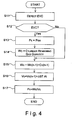
- Figure 4 is a flowchart for calculating a cylinder internal pressure used for calculating the cylinder intake air quantity in the cylinder intake air quantity determination device in accordance with the preferred embodiment of the present invention.
- FIG. 1 is a schematic diagram of the internal combustion engine 1.
- Figure 1 various parameters used for calculating a cylinder intake air quantity are shown in Figure 1.
- the internal combustion engine 1 includes a plurality of combustion chambers (only one combustion chamber is shown) formed by a plurality of pistons 2 (only one piston is shown) and a plurality of cylinders 3 (only one cylinder is shown) of the internal combustion engine 1, respectively.
- Each combustion chamber is preferably equipped with an electromagnetically driven intake valve 5 and an electromagnetically driven exhaust valve 6, and a spark plug 4 disposed between the intake valve 5 and the exhaust valve 6.
- the internal combustion engine 1 includes a plurality of intake air passages 7 coupled to the combustion chambers, an intake manifold 8 installed along the intake air passages 7, and a plurality of exhaust air passages 9.
- the cylinder intake air quantity determination device of the present invention applies to a multicylinder engine even though the following description of the cylinder intake air quantity determination device of the present invention refers only to one cylinder or combustion chamber.
- the intake valve 5 and the exhaust valve 6 are preferably controlled by electromagnetic variable valve timing devices 5a and 6a, respectively.
- the variable valve timing devices 5a and 6a are configured and arranged to variably control lift amount and opening/closing timing of the intake valve 5 and the exhaust valve 6, respectively.
- the variable valve timing control of the intake valve 5 and the exhaust valve 6 is not limited to be performed by the electromagnetic variable valve timing devices 5a and 6a illustrated in Figure 1.
- the internal combustion engine 1 can be configured and arranged to include a mechanical variable valve timing mechanism equipped with cams and lifters so that the lift amount and the opening/closing timing of the intake valve 5 and the exhaust valve 6 are controlled as desired by the mechanical variable valve timing mechanism.
- the electromagnetic variable valve timing devices 5a and 6a and the mechanical variable valve timing mechanism are conventional components that are well known in the art. Since the electromagnetic variable valve timing devices 5a and 6a and the mechanical variable valve timing mechanism are well known in the art, these structures will not be discussed or illustrated in detail herein.
- An electrical throttle valve 10 is provided to the intake air passage 7 at an upstream position of the intake manifold 8.
- the intake air passage 7 is also preferably provided with an electromagnetic fuel injector valve 11 at an intake port portion of the cylinder 3 as seen in Figure 1.
- the internal combustion engine 1 further includes an ECU or engine control unit 12 configured and arranged to control the operation of the spark plug 4, the variable valve timing devices 5a and 6a, the electrical throttle valve 10, the fuel injector valve 11 and other components of the internal combustion engine 1.
- ECU or engine control unit 12 configured and arranged to control the operation of the spark plug 4, the variable valve timing devices 5a and 6a, the electrical throttle valve 10, the fuel injector valve 11 and other components of the internal combustion engine 1.
- control unit 12 preferably includes a microcomputer with a cylinder intake air quantity calculation control program that controls the calculation of the cylinder intake air quantity as discussed below.
- the control unit 12 can also include other conventional components such as an input interface circuit, an output interface circuit, and storage devices such as a ROM (Read Only Memory) device and a RAM (Random Access Memory) device.
- the microcomputer of the control unit 12 is programmed to control the various components of the internal combustion engine 1.
- the memory circuit stores processing results and control programs such as ones for the cylinder intake air quantity calculation operation that are run by the processor circuit.
- the control unit 12 is operatively coupled to the various components of the internal combustion engine 1 in a conventional manner.
- the internal RAM of the control unit 12 stores statuses of operational flags and various control data.
- the internal ROM of the control unit 12 stores data for various operations.
- the control unit 12 is capable of selectively controlling any of the components of its control system in accordance with the control program. It will be apparent to those skilled in the art from this disclosure that the precise structure and algorithms for the control unit 12 can be any combination of hardware and software that will carry out the functions of the cylinder intake air quantity determination device of the present invention.
- "means plus function" clauses as utilized in the specification and claims should include any structure or hardware and/or algorithm or software that can be utilized to carry out the function of the "means plus function” clause.
- control unit 12 is configured and arranged to receive input signals from a crank angle sensor 13, an accelerator pedal sensor 14, a hot-wire air flow meter 15, a temperature sensor 16, an exhaust pressure sensor 17, and the like.
- the crank angle sensor 13 is configured and arranged to output a crank angle signal synchronized to engine revolution to the control unit 12 to detect an engine speed Ne and the crank angle position Ca.
- the accelerator pedal sensor 14 is configured and arranged to detect an accelerator opening degree (how much the accelerator pedal is depressed) and produce an output signal indicative of the accelerator opening degree, which is sent to the control unit 12.
- the hot-wire air flow meter 15 is configured and arranged to detect an air flow quantity Qa (mass flow; g) in the intake air passage 7 from the electrical throttle valve 10 to an upstream portion of the intake manifold 8 and produce an output signal indicative of the air flow quantity Qa, which is sent to the control unit 12.
- the temperature sensor 16 is configured and arranged to detect an intake air temperature Tm (K) inside the intake manifold 8 and produce an output signal indicative of the intake air temperature Tm, which is sent to the control unit 12.
- the exhaust pressure sensor 17 is configured and arranged to detect an exhaust pressure Pex (Pa) in the exhaust air passage 9 and produce an output signal indicative of the exhaust pressure Pex, which is sent to the control unit 12.
- the control unit 12 can be configured and arranged to receive input signals from an exhaust temperature sensor 24, an intake air pressure sensor 25, a water temperature sensor 26, and a pair of intake and exhaust cam angle sensors 27 and 28 as seen in Figure 1.
- the control unit 12 is configured and arranged to control the fuel injection timing and fuel injection quantity of the fuel injector valve 11 based on the engine operating conditions. More specifically, the control unit 12 is configured and arranged to control the fuel injection quantity to achieve a desired air-fuel ratio with respect to a cylinder intake air quantity Cc (air mass inside the cylinder 3), which is calculated based on the inflow air quantity (mass flow) Qa measured by the air flow meter 15 and other parameters as discussed in more detail below.
- Cc air mass inside the cylinder 3
- control unit 12 is configured and arranged to control the ignition timing of the spark plug 4 to achieve the MBT (e.g., ideal ignition timing for best torque) or at the knock limit based on the engine operating conditions.
- MBT e.g., ideal ignition timing for best torque
- Figure 2 is a control block diagram for explaining a calculation of the cylinder intake air quantity Cc (air mass quantity inside the cylinder 3) that is used for controlling the fuel injection quantity and so forth.
- the cylinder intake air quantity determination device of the present invention is configured and arranged to calculate the cylinder intake air quantity with a good precision when the cylinder intake air quantity changes such as when the valve timing changes or when there is a pressure difference between before and after the intake valve 5 during low valve lift operation.
- the cylinder intake air quantity determination device of the present invention basically comprises a manifold internal model including a manifold internal air quantity calculation section 20 and a manifold internal pressure calculation section 21, and a cylinder internal model including a cylinder internal pressure calculation section 22 and a cylinder intake air quantity calculation section 23.
- the cylinder intake air quantity Cc of the internal combustion engine 1 is calculated by the manifold internal model and the cylinder internal model of the cylinder intake air quantity determination device.
- the manifold internal air quantity calculation section 20 is configured and arranged to calculate a manifold internal air quantity Cm (g) based on a balance between the inflow air quantity Qa to the intake manifold 8 and an outflow air quantity (mass; g) from the intake manifold 8.
- the inflow air quantity Qa to the intake manifold 8 is calculated based on the output signal from the air flow meter 15.
- the outflow air quantity from the intake manifold 8 is equal to a previous value of the cylinder intake air quantity Cc(n-1) calculated in a preceding control routine.
- the manifold internal pressure calculation section 21 is configured and arranged to calculate a manifold internal pressure Pm (Pa) inside the intake manifold 8 based on the manifold internal air quantity Cm and the intake air temperature Tm (the vapor temperature inside the intake manifold 8) determined based on the output signal from the temperature sensor 16. More specifically, the manifold internal pressure Pm is calculated by multiplying the manifold internal air quantity Cm, a gas constant R, and the intake air temperature Tm, and dividing this product by a manifold volume Vm (m 3 ), as shown in the following Equation 1.
- the cylinder internal pressure calculation section 22 is configured and arranged to calculate a cylinder internal pressure Pc (Pa) corresponding to the crank angle Ca detected by the crank angle sensor 13. Accordingly, the outflow air quantity Cc(n-1) from the intake manifold 8 and the crank angle Ca are inputted to the cylinder internal pressure calculation section 22.
- the cylinder internal pressure Pc is calculated by dividing the cylinder internal air quantity Wc (quantity of gas remaining in the cylinder 3) by a cylinder volume Vc (m 3 ), as shown by the following Equation 2. The calculation of the cylinder internal air quantity Wc and the cylinder internal pressure Pc will be discussed in more detail below with referring a flowchart of Figure 4.
- the cylinder intake air quantity calculation section 23 is configured and arranged to calculate the cylinder intake air quantity Cc based on the intake air temperature Tm determined based on the output signal from the temperature sensor 16 and the calculation results of the manifold internal pressure Pm in the manifold internal pressure calculation section 21 and the cylinder internal pressure Pc in the cylinder internal pressure calculation section 22. More specifically, the cylinder intake air quantity Cc is calculated by the following Equation 3, using ⁇ as a prescribed value (e.g., specific heat ratio) and Ai as an opening surface area of the intake valve 5.
- the cylinder intake air quantity Cc calculated here becomes the outflow air quantity from the intake manifold 8, which is used as the previous value Cc(n-1) when the next cylinder intake air quantity Cc is calculated in the next control cycle.
- the cylinder intake air quantity Cc is divided by the opening surface area Ai of the intake valve 5 and the gas density ⁇ inside the cylinder 3 to calculate a cylinder inflow velocity Vi (intake valve passage velocity) as shown by the following Equation 4.
- V i C c / A i ⁇ ⁇
- the cylinder inflow velocity Vi can be utilized to estimate a pattern or influence of the peripheral flow (wall flow) of fuel that is adhered on the head portion of the intake valve 5.
- the operation of the internal combustion engine 1 can be effectively controlled by taking the influence of the peripheral flow of fuel into account.
- step S1 of Figure 3 the intake air temperature Tm inside the intake manifold 8, as detected by the temperature sensor 16, is read by the control unit 12.
- This step S corresponds to a temperature calculation section for calculating the intake air temperature Tm.
- step S2 the manifold internal air quantity Cm inside the intake manifold 8 is calculated based on the balance between the inflow air quantity Qa to the intake manifold 8 and the outflow air quantity Cc(n-1) from the intake manifold 8.
- the step S2 corresponds to the manifold internal air quantity calculation section 20 in Figure 2.
- step S3 the manifold internal pressure Pm inside the intake manifold 8 is calculated.
- the manifold internal pressure Pm is calculated based on the manifold internal air quantity Cm, the intake air temperature Tm, and the manifold volume Vm, as shown by Equation 1 above.
- the step S3 corresponds to the manifold internal pressure calculation section 21 in Figure 2.
- step S4 the cylinder internal pressure Pc is calculated based on the cylinder internal air quantity Wc and the cylinder volume Vc, as shown in Equation 2 above.
- the step S4 corresponds to the cylinder internal pressure calculation section 22 in Figure 2.
- step S5 the cylinder intake air quantity Cc is calculated based on the intake air temperature Tm, the manifold internal pressure Pm, and the cylinder internal pressure Pc, as shown in Equation 3 above.
- the step S5 corresponds to the cylinder intake air quantity calculation section 23 in Figure 2.
- step S6 the cylinder inflow velocity Vi is calculated based on the cylinder intake air quantity Cc and the opening surface area Ai of the intake valve 5, as shown in Equation 4 above.
- the cylinder inflow velocity Vi can be calculated with a good precision since the manifold internal pressure Pm inside the intake manifold 8 and the cylinder internal pressure Pc inside the cylinder 3 is taken into account in calculating the cylinder inflow velocity Vi.
- calculating the cylinder inflow velocity Vi allows to take into account the influence of fuel adhering to the head portion of the intake valve 5 after the fuel is injected from the injector valve 11 (i.e., peripheral flow).
- This step S6 corresponds to a cylinder inflow velocity calculation section of the present invention.
- an exhaust valve closing period EVC corresponding to a period during which the exhaust valve 6 is closed is detected.
- the exhaust valve closing period EVC can be detected directly by providing a lift sensor to the exhaust valve 6, or based on a valve closing command value controlled by the control unit 12.
- the exhaust valve closing period EVC can be determined based on the signal outputted from the crank angle sensor 13.
- step S12 it is determined whether or not the exhaust valve 6 is in the exhaust valve closing period EVC. If the exhaust valve 6 is in the exhaust valve closing period EVC (i.e., when the exhaust valve 6 is closed), the control proceeds to step S 13. If the exhaust valve 6 is not in the exhaust valve closing period EVC (i.e., the exhaust valve 6 is open), the control proceeds to step S15.
- step S 13 the cylinder internal pressure Pc is set equal to the exhaust pressure Pex determined based on the output signal from the exhaust pressure sensor 17.
- step S 14 the cylinder internal air quantity Wc is set equal to a quantity of gas remaining in the cylinder 3 (an internal EGR quantity).
- the quantity of gas remaining in the cylinder 3 is preferably calculated, for example, as disclosed in Japanese Patent Application No. 2002-272670.
- a cylinder internal temperature Tc and the cylinder internal pressure Pc during the exhaust valve closing period EVC are calculated based on the output signals from the exhaust temperature sensor 24, the intake air pressure sensor 25, and the exhaust pressure sensor 17.
- a gas constant for the exhaust gas corresponding to the air-fuel ratio is calculated.
- the quantity of blow-back gas during overlap between an open period of the intake valve 5 and an open period of the exhaust valve 6 is calculated based on the output signal from the crank angle sensor 13, the water temperature sensor 26, the intake and exhaust cam angle sensors 27 and 28, and the accelerator pedal sensor 14.
- the quantity of gas remaining in the cylinder 3 (the internal EGR quantity) is then calculated based on the calculated quantity of gas in the cylinder 3 and the calculated quantity of blow-back gas.
- the cylinder internal pressure Pc, then the exhaust gas temperature and the gas constant can be calculated based on the exhaust pressure Pex.
- the quantity of gas remaining in the cylinder 3 during the exhaust valve closing period EVC can be calculated based at least on the calculated values.
- the quantity of blow-back gas during overlap can be calculated, and the quantity of gas remaining in the cylinder 3 (the internal EGR quantity) can be calculated based on the quantity of gas in the cylinder 3 and the quantity of blow-back gas.
- the quantity of gas in the cylinder 3 during the exhaust valve closing period EVC can be calculated based at least on an estimated temperature inside the cylinder 3 during the exhaust valve closing period EVC, a calculated cylinder internal pressure Pc, and a calculated gas constant. Then, the amount of blow-back gas during the valve overlap is calculated.
- the estimated temperature inside the cylinder 3 is calculated by calculating the average temperature inside the cylinder 3 when the engine is in a steady state, and imparting a time delay with respect to changes in the average temperature inside the cylinder 3.
- the quantity of remaining gas in the cylinder 3 is then calculated based on the quantity of gas inside the cylinder 3 and the quantity of blow-back gas.
- step S 15 a current cylinder internal air quantity Wc is calculated by adding the inflow air quantity Cc(n-1) calculated in step S5 to a previous value Wc(n-1) of the cylinder internal air quantity Wc.
- a current cylinder volume Vc is calculated by multiplying a piston crown surface area Ac by a stroke ⁇ ST (a traveling distance) of the piston 2, and adding this product to the previous value Vc(n-1) of the cylinder volume Vc.
- step S17 a current cylinder internal pressure Pc is calculated by dividing the cylinder internal air quantity Wc calculated in step S 15 by the cylinder volume Vc calculated in step S16.
- the cylinder intake air quantity determination device of the present embodiment basically comprises the manifold internal air quantity calculation section 20, the manifold internal pressure calculation section 21, the cylinder internal pressure calculation section 22, and the cylinder intake air quantity calculation section 23.
- the manifold internal air quantity calculation section is configured and arranged to calculate the manifold internal air quantity Cm based on the balance between the inflow air quantity Qa to the intake manifold 8 and the outflow air quantity Cc(n-1) from the intake manifold 8 (step S2 in Figure 3).
- the manifold internal pressure calculation section 21 is configured and arranged to calculate the manifold internal pressure Pm based at least on the manifold internal air quantity Cm calculated in the manifold internal air quantity calculation section 20 (step S3 in Figure 3).
- the cylinder internal pressure calculation section 22 is configured and arranged to calculate the cylinder internal pressure Pc based at least on one of the cylinder volume Vc, the exhaust pressure Pex, and the cylinder internal air quantity Wc, which are parameters that affect the gas state inside the cylinder 3 (step S4 in Figure 3 and steps S 11 to S 17 in Figure 4).
- the cylinder intake air quantity calculation section 23 is configured and arranged to calculate the cylinder intake air quantity Cc based on the manifold internal pressure Pm and the cylinder internal pressure Pc (step S5 in Figure 3).
- the cylinder intake air quantity Cc can be calculated with a good precision corresponding to these changes.
- the cylinder intake air quantity determination device of the present embodiment further comprises a temperature calculation section (step S1 in Figure 3) configured and arranged to calculate the intake air temperature Tm based on the output signal from the temperature sensor 16, and the manifold internal pressure calculation section 21 is configured and arranged to calculate the manifold internal pressure Pm based on the manifold internal air quantity Cm and the intake air temperature Tm. Accordingly, the pressure Pm inside the intake manifold 8 can be calculated with a good precision based on the manifold internal air quantity Cm and the intake air temperature Tm. Thus, the cylinder intake air quantity Cc can also be calculated with a good precision.
- the cylinder intake air quantity determination device of the present embodiment comprises a temperature calculation section (step S 1 in Figure 3) as mentioned above, and the cylinder intake air quantity calculation section 23 is further configured and arranged to calculate the cylinder intake air quantity Cc based on the manifold internal pressure Pm, the cylinder internal pressure Pc, and the intake air temperature Tm. Therefore, the cylinder intake air quantity Cc can be calculated as shown in Equation 3 above.
- the manifold internal air quantity calculation section 20 is configured and arranged to calculate the inflow air quantity Qa to the intake manifold 8 based on the output signal from the air flow meter 15. Therefore, there is no need to provide a separate measurement apparatus.
- the cylinder intake air quantity determination device of the present embodiment also comprises the cylinder inflow velocity calculation section (step S6 in Figure 3) configured and arranged to calculate the cylinder inflow velocity Vi based on the cylinder intake air quantity Cc calculated by the cylinder intake air quantity calculation section 23. Therefore, the cylinder inflow velocity Vi can be calculated as shown in Equation 4, and the influence of peripheral flow on the head portion of the intake valve 5 can be predicted and taken into account in controlling the operation of the internal combustion engine 1.
- the following directional terms "forward, rearward, above, downward, vertical, horizontal, below and transverse” as well as any other similar directional terms refer to those directions of a vehicle equipped with the present invention. Accordingly, these terms, as utilized to describe the present invention should be interpreted relative to a vehicle equipped with the present invention.
- the term "detect” as used herein to describe an operation or function carried out by a component, a section, a device or the like includes a component, a section, a device or the like that does not require physical detection, but rather includes determining or computing or the like to carry out the operation or function.
Applications Claiming Priority (2)
| Application Number | Priority Date | Filing Date | Title |
|---|---|---|---|
| JP2004041888A JP4321294B2 (ja) | 2004-02-18 | 2004-02-18 | 内燃機関のシリンダ吸入空気量算出装置 |
| JP2004041888 | 2004-02-18 |
Publications (2)
| Publication Number | Publication Date |
|---|---|
| EP1566533A1 EP1566533A1 (en) | 2005-08-24 |
| EP1566533B1 true EP1566533B1 (en) | 2006-07-26 |
Family
ID=34709100
Family Applications (1)
| Application Number | Title | Priority Date | Filing Date |
|---|---|---|---|
| EP05002174A Expired - Fee Related EP1566533B1 (en) | 2004-02-18 | 2005-02-02 | Cylinder intake air quantity calculation device |
Country Status (6)
| Country | Link |
|---|---|
| US (1) | US7025041B2 (zh) |
| EP (1) | EP1566533B1 (zh) |
| JP (1) | JP4321294B2 (zh) |
| KR (1) | KR100668555B1 (zh) |
| CN (1) | CN100404831C (zh) |
| DE (1) | DE602005000052T2 (zh) |
Families Citing this family (42)
| Publication number | Priority date | Publication date | Assignee | Title |
|---|---|---|---|---|
| US9733625B2 (en) | 2006-03-20 | 2017-08-15 | General Electric Company | Trip optimization system and method for a train |
| US10569792B2 (en) | 2006-03-20 | 2020-02-25 | General Electric Company | Vehicle control system and method |
| US10308265B2 (en) | 2006-03-20 | 2019-06-04 | Ge Global Sourcing Llc | Vehicle control system and method |
| US9950722B2 (en) | 2003-01-06 | 2018-04-24 | General Electric Company | System and method for vehicle control |
| FR2863006B1 (fr) * | 2003-12-02 | 2006-02-24 | Inst Francais Du Petrole | Procede de controle d'un moteur surlalimente, notamment d'un moteur a injection indirecte, et moteur utilisant un tel procede |
| FR2892453B1 (fr) * | 2005-10-24 | 2010-12-17 | Renault Sas | Procede et dispositif pour estimer la pression regnant dans le collecteur d'admission d'un moteur a combustion interne |
| JP4465665B2 (ja) * | 2005-11-29 | 2010-05-19 | トヨタ自動車株式会社 | 内燃機関の制御装置および制御方法 |
| JP5002987B2 (ja) * | 2006-03-08 | 2012-08-15 | 日産自動車株式会社 | エンジンのシリンダ吸入ガス量計測装置 |
| US9828010B2 (en) | 2006-03-20 | 2017-11-28 | General Electric Company | System, method and computer software code for determining a mission plan for a powered system using signal aspect information |
| US9156477B2 (en) | 2006-03-20 | 2015-10-13 | General Electric Company | Control system and method for remotely isolating powered units in a vehicle system |
| US7630823B2 (en) | 2007-09-20 | 2009-12-08 | General Electric Company | System and method for controlling the fuel injection event in an internal combustion engine |
| US8527183B2 (en) | 2007-09-20 | 2013-09-03 | General Electric Company | System and method for controlling the fuel injection event in an internal combustion engine |
| JP5104786B2 (ja) * | 2009-03-06 | 2012-12-19 | トヨタ自動車株式会社 | 内燃機関の制御装置 |
| US9834237B2 (en) | 2012-11-21 | 2017-12-05 | General Electric Company | Route examining system and method |
| EP2388461A1 (en) * | 2010-05-21 | 2011-11-23 | C.R.F. Società Consortile per Azioni | Internal exhaust gas recirculation control in an internal combustion engine |
| CN102062005B (zh) * | 2010-12-30 | 2014-04-02 | 天津锐意泰克汽车电子有限公司 | 一种计算发动机进气量及进气压力的方法 |
| US9638121B2 (en) | 2012-08-24 | 2017-05-02 | GM Global Technology Operations LLC | System and method for deactivating a cylinder of an engine and reactivating the cylinder based on an estimated trapped air mass |
| US9726139B2 (en) | 2012-09-10 | 2017-08-08 | GM Global Technology Operations LLC | System and method for controlling a firing sequence of an engine to reduce vibration when cylinders of the engine are deactivated |
| US9650978B2 (en) | 2013-01-07 | 2017-05-16 | GM Global Technology Operations LLC | System and method for randomly adjusting a firing frequency of an engine to reduce vibration when cylinders of the engine are deactivated |
| US9719439B2 (en) | 2012-08-24 | 2017-08-01 | GM Global Technology Operations LLC | System and method for controlling spark timing when cylinders of an engine are deactivated to reduce noise and vibration |
| US9534550B2 (en) | 2012-09-10 | 2017-01-03 | GM Global Technology Operations LLC | Air per cylinder determination systems and methods |
| US9458779B2 (en) * | 2013-01-07 | 2016-10-04 | GM Global Technology Operations LLC | Intake runner temperature determination systems and methods |
| DE102013217250B4 (de) | 2012-09-10 | 2018-08-02 | GM Global Technology Operations LLC (n. d. Gesetzen des Staates Delaware) | Luftmassenermittlung für steuersysteme zur zylinderaktivierung und -deaktivierung |
| US9669851B2 (en) | 2012-11-21 | 2017-06-06 | General Electric Company | Route examination system and method |
| DE102012221311B4 (de) * | 2012-11-22 | 2014-07-10 | Continental Automotive Gmbh | Verfahren zur Frischlufterfassung durch Auswertung eines Zylinderinnendrucksignals |
| US20140172277A1 (en) * | 2012-12-18 | 2014-06-19 | Caterpillar Inc. | Engine diagnostic system and method |
| JP5865942B2 (ja) * | 2014-04-16 | 2016-02-17 | 三菱電機株式会社 | 内燃機関のシリンダ吸入空気量推定装置および推定方法 |
| US9556811B2 (en) | 2014-06-20 | 2017-01-31 | GM Global Technology Operations LLC | Firing pattern management for improved transient vibration in variable cylinder deactivation mode |
| US9599047B2 (en) | 2014-11-20 | 2017-03-21 | GM Global Technology Operations LLC | Combination cylinder state and transmission gear control systems and methods |
| US10337441B2 (en) | 2015-06-09 | 2019-07-02 | GM Global Technology Operations LLC | Air per cylinder determination systems and methods |
| DE102015210761A1 (de) * | 2015-06-12 | 2016-12-15 | Volkswagen Aktiengesellschaft | Luftfüllungsbestimmung, Motorsteuergerät und Verbrennungskraftmaschine |
| US10655550B2 (en) | 2015-07-13 | 2020-05-19 | GM Global Technology Operations LLC | Intake manifold and cylinder airflow estimation systems and methods |
| US10240545B2 (en) * | 2015-12-21 | 2019-03-26 | Ford Global Technologies, Llc | Air charge estimation via manifold pressure sample at intake valve closing |
| CN107288768B (zh) * | 2016-03-31 | 2019-08-23 | 广州汽车集团股份有限公司 | 内燃机阿特金森循环进气量的计算方法以及系统 |
| CN106226087A (zh) * | 2016-10-08 | 2016-12-14 | 潍柴西港新能源动力有限公司 | 一种发动机各缸进气分配均匀性直接测量装置及方法 |
| KR102406117B1 (ko) * | 2016-12-14 | 2022-06-07 | 현대자동차 주식회사 | 연료 분사 제어 장치 및 방법 |
| JP6899224B2 (ja) * | 2017-01-26 | 2021-07-07 | 三菱重工エンジン&ターボチャージャ株式会社 | 副室式ガスエンジン |
| US11739701B2 (en) * | 2018-11-08 | 2023-08-29 | Marelli Europe S.P.A. | Method to determine the mass of air trapped in each cylinder of an internal combustion engine |
| DE102019211398A1 (de) * | 2019-07-31 | 2021-02-04 | Ford Global Technologies, Llc | Bestimmen einer Innenzylinderluftmasse |
| DE102019213092A1 (de) * | 2019-08-30 | 2021-03-04 | Volkswagen Aktiengesellschaft | Verfahren zur Diagnostik von Verbrennungsaussetzern einer Verbrennungskraftmaschine |
| CN110566358B (zh) * | 2019-09-30 | 2022-03-01 | 潍柴动力股份有限公司 | 发动机起动控制方法、装置、设备及存储介质 |
| KR102276496B1 (ko) * | 2020-12-16 | 2021-07-12 | 비테스코 테크놀로지스 게엠베하 | 전동식 슈퍼차져 시스템의 공기량 추정 방법 |
Family Cites Families (13)
| Publication number | Priority date | Publication date | Assignee | Title |
|---|---|---|---|---|
| JPH02277939A (ja) * | 1989-01-07 | 1990-11-14 | Mitsubishi Electric Corp | エンジンの燃料制御装置 |
| US5331936A (en) * | 1993-02-10 | 1994-07-26 | Ford Motor Company | Method and apparatus for inferring the actual air charge in an internal combustion engine during transient conditions |
| DE4325902C2 (de) | 1993-08-02 | 1999-12-02 | Bosch Gmbh Robert | Verfahren zur Berechnung der Luftfüllung für eine Brennkraftmaschine mit variabler Gaswechselsteuerung |
| US6122589A (en) * | 1998-04-09 | 2000-09-19 | Yamah Hatsudoki Kabushiki Kaisha | Fuel injection control system for engine |
| US6089082A (en) * | 1998-12-07 | 2000-07-18 | Ford Global Technologies, Inc. | Air estimation system and method |
| JP2001050091A (ja) | 1999-08-06 | 2001-02-23 | Nissan Motor Co Ltd | 可変動弁エンジンのシリンダ吸入空気量算出装置 |
| JP2002070633A (ja) * | 2000-08-31 | 2002-03-08 | Denso Corp | 内燃機関の筒内充填空気量推定装置 |
| JP3767426B2 (ja) | 2001-06-14 | 2006-04-19 | 日産自動車株式会社 | エンジンのシリンダ吸入空気量算出装置 |
| CN100343499C (zh) * | 2001-10-15 | 2007-10-17 | 丰田自动车株式会社 | 内燃机的进气量估算装置 |
| JP3767484B2 (ja) | 2002-01-18 | 2006-04-19 | 日産自動車株式会社 | エンジンのシリンダ吸入空気量測定装置 |
| JP3724425B2 (ja) * | 2002-01-18 | 2005-12-07 | 日産自動車株式会社 | エンジンのシリンダ吸入空気量測定装置 |
| US6999864B2 (en) | 2002-07-15 | 2006-02-14 | Hitachi, Ltd. | Apparatus and method for estimating residual gas amount of internal combustion engine, and apparatus and method for controlling intake air amount of internal combustion engine using estimated residual gas amount |
| JP4154972B2 (ja) | 2002-09-19 | 2008-09-24 | 日産自動車株式会社 | 内燃機関の内部egr量推定装置 |
-
2004
- 2004-02-18 JP JP2004041888A patent/JP4321294B2/ja not_active Expired - Fee Related
-
2005
- 2005-01-07 US US11/030,200 patent/US7025041B2/en not_active Expired - Fee Related
- 2005-02-02 DE DE602005000052T patent/DE602005000052T2/de active Active
- 2005-02-02 EP EP05002174A patent/EP1566533B1/en not_active Expired - Fee Related
- 2005-02-17 KR KR1020050012947A patent/KR100668555B1/ko not_active IP Right Cessation
- 2005-02-18 CN CNB2005100093045A patent/CN100404831C/zh not_active Expired - Fee Related
Also Published As
| Publication number | Publication date |
|---|---|
| JP4321294B2 (ja) | 2009-08-26 |
| KR100668555B1 (ko) | 2007-01-16 |
| CN100404831C (zh) | 2008-07-23 |
| EP1566533A1 (en) | 2005-08-24 |
| DE602005000052T2 (de) | 2007-04-19 |
| JP2005233047A (ja) | 2005-09-02 |
| KR20060042018A (ko) | 2006-05-12 |
| CN1657755A (zh) | 2005-08-24 |
| DE602005000052D1 (de) | 2006-09-07 |
| US20050178361A1 (en) | 2005-08-18 |
| US7025041B2 (en) | 2006-04-11 |
Similar Documents
| Publication | Publication Date | Title |
|---|---|---|
| EP1566533B1 (en) | Cylinder intake air quantity calculation device | |
| US7079937B2 (en) | Air quantity estimation apparatus for internal combustion engine | |
| JP4352830B2 (ja) | 内燃機関の制御装置 | |
| US6328007B1 (en) | Internal cylinder intake-air quantity calculating apparatus and method for variable valve open/closure timing controlled engine | |
| US7107140B2 (en) | Internal combustion engine control apparatus | |
| JPH07208254A (ja) | スロットル式可変排気量往復運動内燃機関用のシリンダ給気量予測装置 | |
| US20110172898A1 (en) | Internal combustion engine system control device | |
| JPH01253543A (ja) | エンジンの空燃比制御装置 | |
| JP4114574B2 (ja) | 内燃機関の吸気量制御装置及び吸気量制御方法 | |
| JP2006307668A (ja) | エンジンのegr流量推定装置 | |
| US20020092506A1 (en) | Fuel injection control system, fuel injection control method, and engine control unit, for internal combustion engine | |
| JP5002987B2 (ja) | エンジンのシリンダ吸入ガス量計測装置 | |
| CN100465422C (zh) | 内燃机的控制装置 | |
| US6494185B2 (en) | Fuel injection control apparatus and method for variably operated engine valve equipped internal combustion | |
| JP2005069020A (ja) | 内燃機関の制御装置 | |
| JP4254389B2 (ja) | 内燃機関の制御装置 | |
| JP4000972B2 (ja) | 内燃機関の筒内ガス状態取得装置 | |
| EP1645742B1 (en) | Internal combustion engine control apparatus | |
| JP2006257989A (ja) | 多気筒内燃機関の制御装置 | |
| JP4241560B2 (ja) | 内燃機関の吸入空気量推定装置 | |
| JPH10220270A (ja) | 内燃機関の燃料噴射量制御装置 | |
| JP2002047951A (ja) | エンジン制御装置 | |
| JP4737191B2 (ja) | 吸気通路容積算出装置 | |
| JPH10339205A (ja) | エンジンの吸気制御装置 | |
| JPH04179844A (ja) | エンジンの燃料制御装置 |
Legal Events
| Date | Code | Title | Description |
|---|---|---|---|
| PUAI | Public reference made under article 153(3) epc to a published international application that has entered the european phase |
Free format text: ORIGINAL CODE: 0009012 |
|
| 17P | Request for examination filed |
Effective date: 20050202 |
|
| AK | Designated contracting states |
Kind code of ref document: A1 Designated state(s): AT BE BG CH CY CZ DE DK EE ES FI FR GB GR HU IE IS IT LI LT LU MC NL PL PT RO SE SI SK TR |
|
| AX | Request for extension of the european patent |
Extension state: AL BA HR LV MK YU |
|
| GRAP | Despatch of communication of intention to grant a patent |
Free format text: ORIGINAL CODE: EPIDOSNIGR1 |
|
| GRAS | Grant fee paid |
Free format text: ORIGINAL CODE: EPIDOSNIGR3 |
|
| AKX | Designation fees paid |
Designated state(s): DE FR GB |
|
| GRAA | (expected) grant |
Free format text: ORIGINAL CODE: 0009210 |
|
| AK | Designated contracting states |
Kind code of ref document: B1 Designated state(s): DE FR GB |
|
| REG | Reference to a national code |
Ref country code: GB Ref legal event code: FG4D |
|
| REF | Corresponds to: |
Ref document number: 602005000052 Country of ref document: DE Date of ref document: 20060907 Kind code of ref document: P |
|
| ET | Fr: translation filed | ||
| PLBE | No opposition filed within time limit |
Free format text: ORIGINAL CODE: 0009261 |
|
| STAA | Information on the status of an ep patent application or granted ep patent |
Free format text: STATUS: NO OPPOSITION FILED WITHIN TIME LIMIT |
|
| 26N | No opposition filed |
Effective date: 20070427 |
|
| PGFP | Annual fee paid to national office [announced via postgrant information from national office to epo] |
Ref country code: DE Payment date: 20140129 Year of fee payment: 10 |
|
| PGFP | Annual fee paid to national office [announced via postgrant information from national office to epo] |
Ref country code: FR Payment date: 20140211 Year of fee payment: 10 |
|
| PGFP | Annual fee paid to national office [announced via postgrant information from national office to epo] |
Ref country code: GB Payment date: 20140129 Year of fee payment: 10 |
|
| REG | Reference to a national code |
Ref country code: DE Ref legal event code: R119 Ref document number: 602005000052 Country of ref document: DE |
|
| GBPC | Gb: european patent ceased through non-payment of renewal fee |
Effective date: 20150202 |
|
| REG | Reference to a national code |
Ref country code: FR Ref legal event code: ST Effective date: 20151030 |
|
| PG25 | Lapsed in a contracting state [announced via postgrant information from national office to epo] |
Ref country code: DE Free format text: LAPSE BECAUSE OF NON-PAYMENT OF DUE FEES Effective date: 20150901 Ref country code: GB Free format text: LAPSE BECAUSE OF NON-PAYMENT OF DUE FEES Effective date: 20150202 |
|
| PG25 | Lapsed in a contracting state [announced via postgrant information from national office to epo] |
Ref country code: FR Free format text: LAPSE BECAUSE OF NON-PAYMENT OF DUE FEES Effective date: 20150302 |