EP1563991B1 - Bildaufzeichnungsmaterial - Google Patents
Bildaufzeichnungsmaterial Download PDFInfo
- Publication number
- EP1563991B1 EP1563991B1 EP05010866A EP05010866A EP1563991B1 EP 1563991 B1 EP1563991 B1 EP 1563991B1 EP 05010866 A EP05010866 A EP 05010866A EP 05010866 A EP05010866 A EP 05010866A EP 1563991 B1 EP1563991 B1 EP 1563991B1
- Authority
- EP
- European Patent Office
- Prior art keywords
- recording material
- group
- image recording
- heat mode
- compound
- Prior art date
- Legal status (The legal status is an assumption and is not a legal conclusion. Google has not performed a legal analysis and makes no representation as to the accuracy of the status listed.)
- Expired - Lifetime
Links
- 239000000463 material Substances 0.000 title claims abstract description 69
- 150000001875 compounds Chemical class 0.000 claims abstract description 143
- 229920000642 polymer Polymers 0.000 claims abstract description 74
- 238000006243 chemical reaction Methods 0.000 claims abstract description 36
- 239000003513 alkali Substances 0.000 claims abstract description 34
- 239000007864 aqueous solution Substances 0.000 claims abstract description 34
- XLYOFNOQVPJJNP-UHFFFAOYSA-N water Substances O XLYOFNOQVPJJNP-UHFFFAOYSA-N 0.000 claims abstract description 32
- 239000003795 chemical substances by application Substances 0.000 claims abstract description 24
- 238000007639 printing Methods 0.000 claims description 92
- 125000001424 substituent group Chemical group 0.000 claims description 59
- -1 salt compound Chemical class 0.000 claims description 51
- 238000000034 method Methods 0.000 claims description 40
- 125000004435 hydrogen atom Chemical group [H]* 0.000 claims description 20
- 230000008569 process Effects 0.000 claims description 15
- 239000002253 acid Substances 0.000 claims description 13
- 125000000962 organic group Chemical group 0.000 claims description 13
- 229910052717 sulfur Inorganic materials 0.000 claims description 9
- 125000004434 sulfur atom Chemical group 0.000 claims description 9
- 125000004430 oxygen atom Chemical group O* 0.000 claims description 8
- 125000002947 alkylene group Chemical group 0.000 claims description 7
- 125000003178 carboxy group Chemical group [H]OC(*)=O 0.000 claims description 7
- 125000000843 phenylene group Chemical group C1(=C(C=CC=C1)*)* 0.000 claims description 4
- 239000004925 Acrylic resin Substances 0.000 claims 1
- 229920000193 polymethacrylate Polymers 0.000 claims 1
- ANRHNWWPFJCPAZ-UHFFFAOYSA-M thionine Chemical compound [Cl-].C1=CC(N)=CC2=[S+]C3=CC(N)=CC=C3N=C21 ANRHNWWPFJCPAZ-UHFFFAOYSA-M 0.000 claims 1
- 239000010410 layer Substances 0.000 description 68
- 150000003254 radicals Chemical class 0.000 description 67
- 238000011282 treatment Methods 0.000 description 54
- 239000000243 solution Substances 0.000 description 51
- 239000000049 pigment Substances 0.000 description 41
- 125000004432 carbon atom Chemical group C* 0.000 description 39
- 229910052782 aluminium Inorganic materials 0.000 description 34
- XAGFODPZIPBFFR-UHFFFAOYSA-N aluminium Chemical compound [Al] XAGFODPZIPBFFR-UHFFFAOYSA-N 0.000 description 34
- OKKJLVBELUTLKV-UHFFFAOYSA-N Methanol Chemical compound OC OKKJLVBELUTLKV-UHFFFAOYSA-N 0.000 description 30
- 239000000975 dye Substances 0.000 description 30
- 239000000126 substance Substances 0.000 description 23
- 230000015572 biosynthetic process Effects 0.000 description 22
- 238000000576 coating method Methods 0.000 description 22
- 239000011248 coating agent Substances 0.000 description 21
- 239000000203 mixture Substances 0.000 description 21
- ARXJGSRGQADJSQ-UHFFFAOYSA-N 1-methoxypropan-2-ol Chemical compound COCC(C)O ARXJGSRGQADJSQ-UHFFFAOYSA-N 0.000 description 20
- 239000008199 coating composition Substances 0.000 description 20
- 239000004094 surface-active agent Substances 0.000 description 20
- ZWEHNKRNPOVVGH-UHFFFAOYSA-N 2-Butanone Chemical compound CCC(C)=O ZWEHNKRNPOVVGH-UHFFFAOYSA-N 0.000 description 18
- 239000011347 resin Substances 0.000 description 18
- 229920005989 resin Polymers 0.000 description 18
- QAOWNCQODCNURD-UHFFFAOYSA-N Sulfuric acid Chemical compound OS(O)(=O)=O QAOWNCQODCNURD-UHFFFAOYSA-N 0.000 description 16
- 125000000217 alkyl group Chemical group 0.000 description 16
- 150000003839 salts Chemical class 0.000 description 16
- KWYUFKZDYYNOTN-UHFFFAOYSA-M Potassium hydroxide Chemical compound [OH-].[K+] KWYUFKZDYYNOTN-UHFFFAOYSA-M 0.000 description 15
- HEMHJVSKTPXQMS-UHFFFAOYSA-M Sodium hydroxide Chemical compound [OH-].[Na+] HEMHJVSKTPXQMS-UHFFFAOYSA-M 0.000 description 15
- 239000000976 ink Substances 0.000 description 14
- 238000003786 synthesis reaction Methods 0.000 description 14
- 125000003118 aryl group Chemical group 0.000 description 13
- 239000003999 initiator Substances 0.000 description 12
- 238000007788 roughening Methods 0.000 description 12
- NIXOWILDQLNWCW-UHFFFAOYSA-M Acrylate Chemical compound [O-]C(=O)C=C NIXOWILDQLNWCW-UHFFFAOYSA-M 0.000 description 10
- FBPFZTCFMRRESA-FSIIMWSLSA-N D-Glucitol Natural products OC[C@H](O)[C@H](O)[C@@H](O)[C@H](O)CO FBPFZTCFMRRESA-FSIIMWSLSA-N 0.000 description 10
- PPBRXRYQALVLMV-UHFFFAOYSA-N Styrene Chemical compound C=CC1=CC=CC=C1 PPBRXRYQALVLMV-UHFFFAOYSA-N 0.000 description 10
- 238000005516 engineering process Methods 0.000 description 10
- 125000000524 functional group Chemical group 0.000 description 10
- 230000035945 sensitivity Effects 0.000 description 10
- 239000000600 sorbitol Substances 0.000 description 10
- ZMANZCXQSJIPKH-UHFFFAOYSA-N Triethylamine Chemical compound CCN(CC)CC ZMANZCXQSJIPKH-UHFFFAOYSA-N 0.000 description 9
- 239000003792 electrolyte Substances 0.000 description 9
- 125000005843 halogen group Chemical group 0.000 description 9
- 239000007788 liquid Substances 0.000 description 9
- 239000000178 monomer Substances 0.000 description 9
- 239000003921 oil Substances 0.000 description 9
- 230000003287 optical effect Effects 0.000 description 9
- 239000011541 reaction mixture Substances 0.000 description 9
- 238000010186 staining Methods 0.000 description 9
- QGKMIGUHVLGJBR-UHFFFAOYSA-M (4z)-1-(3-methylbutyl)-4-[[1-(3-methylbutyl)quinolin-1-ium-4-yl]methylidene]quinoline;iodide Chemical compound [I-].C12=CC=CC=C2N(CCC(C)C)C=CC1=CC1=CC=[N+](CCC(C)C)C2=CC=CC=C12 QGKMIGUHVLGJBR-UHFFFAOYSA-M 0.000 description 8
- IAZDPXIOMUYVGZ-UHFFFAOYSA-N Dimethylsulphoxide Chemical compound CS(C)=O IAZDPXIOMUYVGZ-UHFFFAOYSA-N 0.000 description 8
- LFQSCWFLJHTTHZ-UHFFFAOYSA-N Ethanol Chemical compound CCO LFQSCWFLJHTTHZ-UHFFFAOYSA-N 0.000 description 8
- CERQOIWHTDAKMF-UHFFFAOYSA-M Methacrylate Chemical compound CC(=C)C([O-])=O CERQOIWHTDAKMF-UHFFFAOYSA-M 0.000 description 8
- 238000002679 ablation Methods 0.000 description 8
- 150000001408 amides Chemical class 0.000 description 8
- QVGXLLKOCUKJST-UHFFFAOYSA-N atomic oxygen Chemical compound [O] QVGXLLKOCUKJST-UHFFFAOYSA-N 0.000 description 8
- 150000001732 carboxylic acid derivatives Chemical class 0.000 description 8
- 230000000052 comparative effect Effects 0.000 description 8
- 238000005227 gel permeation chromatography Methods 0.000 description 8
- 229910052760 oxygen Inorganic materials 0.000 description 8
- 239000001301 oxygen Substances 0.000 description 8
- 238000006116 polymerization reaction Methods 0.000 description 8
- BWHMMNNQKKPAPP-UHFFFAOYSA-L potassium carbonate Chemical compound [K+].[K+].[O-]C([O-])=O BWHMMNNQKKPAPP-UHFFFAOYSA-L 0.000 description 8
- CERQOIWHTDAKMF-UHFFFAOYSA-N Methacrylic acid Chemical compound CC(=C)C(O)=O CERQOIWHTDAKMF-UHFFFAOYSA-N 0.000 description 7
- 229910019142 PO4 Inorganic materials 0.000 description 7
- NBIIXXVUZAFLBC-UHFFFAOYSA-N Phosphoric acid Chemical group OP(O)(O)=O NBIIXXVUZAFLBC-UHFFFAOYSA-N 0.000 description 7
- 235000010724 Wisteria floribunda Nutrition 0.000 description 7
- 125000003545 alkoxy group Chemical group 0.000 description 7
- 239000010407 anodic oxide Substances 0.000 description 7
- 150000002430 hydrocarbons Chemical group 0.000 description 7
- 238000004519 manufacturing process Methods 0.000 description 7
- 230000001590 oxidative effect Effects 0.000 description 7
- 239000010452 phosphate Substances 0.000 description 7
- 238000002360 preparation method Methods 0.000 description 7
- 239000007787 solid Substances 0.000 description 7
- WMFOQBRAJBCJND-UHFFFAOYSA-M Lithium hydroxide Chemical compound [Li+].[OH-] WMFOQBRAJBCJND-UHFFFAOYSA-M 0.000 description 6
- ZMXDDKWLCZADIW-UHFFFAOYSA-N N,N-Dimethylformamide Chemical compound CN(C)C=O ZMXDDKWLCZADIW-UHFFFAOYSA-N 0.000 description 6
- GRYLNZFGIOXLOG-UHFFFAOYSA-N Nitric acid Chemical compound O[N+]([O-])=O GRYLNZFGIOXLOG-UHFFFAOYSA-N 0.000 description 6
- 239000004793 Polystyrene Substances 0.000 description 6
- YXFVVABEGXRONW-UHFFFAOYSA-N Toluene Chemical compound CC1=CC=CC=C1 YXFVVABEGXRONW-UHFFFAOYSA-N 0.000 description 6
- 239000002250 absorbent Substances 0.000 description 6
- 230000002745 absorbent Effects 0.000 description 6
- 238000010521 absorption reaction Methods 0.000 description 6
- 239000011230 binding agent Substances 0.000 description 6
- 238000001035 drying Methods 0.000 description 6
- 125000002496 methyl group Chemical group [H]C([H])([H])* 0.000 description 6
- 229910017604 nitric acid Inorganic materials 0.000 description 6
- 125000000449 nitro group Chemical group [O-][N+](*)=O 0.000 description 6
- 125000002467 phosphate group Chemical group [H]OP(=O)(O[H])O[*] 0.000 description 6
- 239000003505 polymerization initiator Substances 0.000 description 6
- 229920002223 polystyrene Polymers 0.000 description 6
- 238000010526 radical polymerization reaction Methods 0.000 description 6
- 239000002904 solvent Substances 0.000 description 6
- 238000003756 stirring Methods 0.000 description 6
- 238000001308 synthesis method Methods 0.000 description 6
- NIXOWILDQLNWCW-UHFFFAOYSA-N 2-Propenoic acid Natural products OC(=O)C=C NIXOWILDQLNWCW-UHFFFAOYSA-N 0.000 description 5
- FBPFZTCFMRRESA-JGWLITMVSA-N D-glucitol Chemical compound OC[C@H](O)[C@@H](O)[C@H](O)[C@H](O)CO FBPFZTCFMRRESA-JGWLITMVSA-N 0.000 description 5
- YCKRFDGAMUMZLT-UHFFFAOYSA-N Fluorine atom Chemical compound [F] YCKRFDGAMUMZLT-UHFFFAOYSA-N 0.000 description 5
- VEXZGXHMUGYJMC-UHFFFAOYSA-N Hydrochloric acid Chemical compound Cl VEXZGXHMUGYJMC-UHFFFAOYSA-N 0.000 description 5
- JUJWROOIHBZHMG-UHFFFAOYSA-N Pyridine Chemical compound C1=CC=NC=C1 JUJWROOIHBZHMG-UHFFFAOYSA-N 0.000 description 5
- 239000004115 Sodium Silicate Substances 0.000 description 5
- 229910052910 alkali metal silicate Inorganic materials 0.000 description 5
- 125000003277 amino group Chemical group 0.000 description 5
- 229920001577 copolymer Polymers 0.000 description 5
- 230000000694 effects Effects 0.000 description 5
- 229910052731 fluorine Inorganic materials 0.000 description 5
- 239000011737 fluorine Substances 0.000 description 5
- 230000005764 inhibitory process Effects 0.000 description 5
- 235000011118 potassium hydroxide Nutrition 0.000 description 5
- 239000011241 protective layer Substances 0.000 description 5
- 239000004576 sand Substances 0.000 description 5
- 239000004065 semiconductor Substances 0.000 description 5
- 235000011121 sodium hydroxide Nutrition 0.000 description 5
- NTHWMYGWWRZVTN-UHFFFAOYSA-N sodium silicate Chemical compound [Na+].[Na+].[O-][Si]([O-])=O NTHWMYGWWRZVTN-UHFFFAOYSA-N 0.000 description 5
- 229910052911 sodium silicate Inorganic materials 0.000 description 5
- 238000004381 surface treatment Methods 0.000 description 5
- 238000012719 thermal polymerization Methods 0.000 description 5
- ROVRRJSRRSGUOL-UHFFFAOYSA-N victoria blue bo Chemical compound [Cl-].C12=CC=CC=C2C(NCC)=CC=C1C(C=1C=CC(=CC=1)N(CC)CC)=C1C=CC(=[N+](CC)CC)C=C1 ROVRRJSRRSGUOL-UHFFFAOYSA-N 0.000 description 5
- SMZOUWXMTYCWNB-UHFFFAOYSA-N 2-(2-methoxy-5-methylphenyl)ethanamine Chemical compound COC1=CC=C(C)C=C1CCN SMZOUWXMTYCWNB-UHFFFAOYSA-N 0.000 description 4
- XLLIQLLCWZCATF-UHFFFAOYSA-N 2-methoxyethyl acetate Chemical compound COCCOC(C)=O XLLIQLLCWZCATF-UHFFFAOYSA-N 0.000 description 4
- IJGRMHOSHXDMSA-UHFFFAOYSA-N Atomic nitrogen Chemical compound N#N IJGRMHOSHXDMSA-UHFFFAOYSA-N 0.000 description 4
- 235000011960 Brassica ruvo Nutrition 0.000 description 4
- QIGBRXMKCJKVMJ-UHFFFAOYSA-N Hydroquinone Chemical compound OC1=CC=C(O)C=C1 QIGBRXMKCJKVMJ-UHFFFAOYSA-N 0.000 description 4
- MUBZPKHOEPUJKR-UHFFFAOYSA-N Oxalic acid Chemical compound OC(=O)C(O)=O MUBZPKHOEPUJKR-UHFFFAOYSA-N 0.000 description 4
- 239000002202 Polyethylene glycol Substances 0.000 description 4
- CDBYLPFSWZWCQE-UHFFFAOYSA-L Sodium Carbonate Chemical compound [Na+].[Na+].[O-]C([O-])=O CDBYLPFSWZWCQE-UHFFFAOYSA-L 0.000 description 4
- 125000001931 aliphatic group Chemical group 0.000 description 4
- 125000004453 alkoxycarbonyl group Chemical group 0.000 description 4
- 125000004104 aryloxy group Chemical group 0.000 description 4
- CREMABGTGYGIQB-UHFFFAOYSA-N carbon carbon Chemical compound C.C CREMABGTGYGIQB-UHFFFAOYSA-N 0.000 description 4
- 239000011203 carbon fibre reinforced carbon Substances 0.000 description 4
- 230000008859 change Effects 0.000 description 4
- 239000007795 chemical reaction product Substances 0.000 description 4
- 238000001816 cooling Methods 0.000 description 4
- 125000002993 cycloalkylene group Chemical group 0.000 description 4
- JHIVVAPYMSGYDF-UHFFFAOYSA-N cyclohexanone Chemical compound O=C1CCCCC1 JHIVVAPYMSGYDF-UHFFFAOYSA-N 0.000 description 4
- 238000011161 development Methods 0.000 description 4
- 230000018109 developmental process Effects 0.000 description 4
- 150000002148 esters Chemical class 0.000 description 4
- 238000005530 etching Methods 0.000 description 4
- LZCLXQDLBQLTDK-UHFFFAOYSA-N ethyl 2-hydroxypropanoate Chemical compound CCOC(=O)C(C)O LZCLXQDLBQLTDK-UHFFFAOYSA-N 0.000 description 4
- 125000002887 hydroxy group Chemical group [H]O* 0.000 description 4
- 150000002500 ions Chemical class 0.000 description 4
- 229910052751 metal Inorganic materials 0.000 description 4
- 239000002184 metal Substances 0.000 description 4
- LVHBHZANLOWSRM-UHFFFAOYSA-N methylenebutanedioic acid Natural products OC(=O)CC(=C)C(O)=O LVHBHZANLOWSRM-UHFFFAOYSA-N 0.000 description 4
- 238000002156 mixing Methods 0.000 description 4
- PSZYNBSKGUBXEH-UHFFFAOYSA-M naphthalene-1-sulfonate Chemical compound C1=CC=C2C(S(=O)(=O)[O-])=CC=CC2=C1 PSZYNBSKGUBXEH-UHFFFAOYSA-M 0.000 description 4
- 239000003960 organic solvent Substances 0.000 description 4
- NWVVVBRKAWDGAB-UHFFFAOYSA-N p-methoxyphenol Chemical compound COC1=CC=C(O)C=C1 NWVVVBRKAWDGAB-UHFFFAOYSA-N 0.000 description 4
- VLTRZXGMWDSKGL-UHFFFAOYSA-M perchlorate Chemical compound [O-]Cl(=O)(=O)=O VLTRZXGMWDSKGL-UHFFFAOYSA-M 0.000 description 4
- 239000002985 plastic film Substances 0.000 description 4
- 229920006255 plastic film Polymers 0.000 description 4
- 238000005498 polishing Methods 0.000 description 4
- 229920001223 polyethylene glycol Polymers 0.000 description 4
- 229910000027 potassium carbonate Inorganic materials 0.000 description 4
- 235000011181 potassium carbonates Nutrition 0.000 description 4
- GEHJYWRUCIMESM-UHFFFAOYSA-L sodium sulfite Chemical compound [Na+].[Na+].[O-]S([O-])=O GEHJYWRUCIMESM-UHFFFAOYSA-L 0.000 description 4
- 238000003860 storage Methods 0.000 description 4
- 125000000020 sulfo group Chemical group O=S(=O)([*])O[H] 0.000 description 4
- 230000003746 surface roughness Effects 0.000 description 4
- JAHNSTQSQJOJLO-UHFFFAOYSA-N 2-(3-fluorophenyl)-1h-imidazole Chemical compound FC1=CC=CC(C=2NC=CN=2)=C1 JAHNSTQSQJOJLO-UHFFFAOYSA-N 0.000 description 3
- IRQWEODKXLDORP-UHFFFAOYSA-N 4-ethenylbenzoic acid Chemical compound OC(=O)C1=CC=C(C=C)C=C1 IRQWEODKXLDORP-UHFFFAOYSA-N 0.000 description 3
- CSCPPACGZOOCGX-UHFFFAOYSA-N Acetone Chemical compound CC(C)=O CSCPPACGZOOCGX-UHFFFAOYSA-N 0.000 description 3
- WVDDGKGOMKODPV-UHFFFAOYSA-N Benzyl alcohol Chemical compound OCC1=CC=CC=C1 WVDDGKGOMKODPV-UHFFFAOYSA-N 0.000 description 3
- 239000004593 Epoxy Substances 0.000 description 3
- XEKOWRVHYACXOJ-UHFFFAOYSA-N Ethyl acetate Chemical compound CCOC(C)=O XEKOWRVHYACXOJ-UHFFFAOYSA-N 0.000 description 3
- LYCAIKOWRPUZTN-UHFFFAOYSA-N Ethylene glycol Chemical compound OCCO LYCAIKOWRPUZTN-UHFFFAOYSA-N 0.000 description 3
- XEEYBQQBJWHFJM-UHFFFAOYSA-N Iron Chemical compound [Fe] XEEYBQQBJWHFJM-UHFFFAOYSA-N 0.000 description 3
- BPQQTUXANYXVAA-UHFFFAOYSA-N Orthosilicate Chemical compound [O-][Si]([O-])([O-])[O-] BPQQTUXANYXVAA-UHFFFAOYSA-N 0.000 description 3
- 238000009825 accumulation Methods 0.000 description 3
- 238000007259 addition reaction Methods 0.000 description 3
- 229910052784 alkaline earth metal Inorganic materials 0.000 description 3
- 125000003282 alkyl amino group Chemical group 0.000 description 3
- 229910045601 alloy Inorganic materials 0.000 description 3
- 239000000956 alloy Substances 0.000 description 3
- 229910000147 aluminium phosphate Inorganic materials 0.000 description 3
- 125000000129 anionic group Chemical group 0.000 description 3
- 150000001450 anions Chemical class 0.000 description 3
- 125000001769 aryl amino group Chemical group 0.000 description 3
- 239000000987 azo dye Substances 0.000 description 3
- 229920001400 block copolymer Polymers 0.000 description 3
- 239000006229 carbon black Substances 0.000 description 3
- 150000007942 carboxylates Chemical class 0.000 description 3
- 125000002843 carboxylic acid group Chemical group 0.000 description 3
- 239000010949 copper Substances 0.000 description 3
- 238000004132 cross linking Methods 0.000 description 3
- LDHQCZJRKDOVOX-NSCUHMNNSA-N crotonic acid Chemical compound C\C=C\C(O)=O LDHQCZJRKDOVOX-NSCUHMNNSA-N 0.000 description 3
- 230000006866 deterioration Effects 0.000 description 3
- 125000004663 dialkyl amino group Chemical group 0.000 description 3
- UAOMVDZJSHZZME-UHFFFAOYSA-N diisopropylamine Chemical compound CC(C)NC(C)C UAOMVDZJSHZZME-UHFFFAOYSA-N 0.000 description 3
- 238000007598 dipping method Methods 0.000 description 3
- 238000005868 electrolysis reaction Methods 0.000 description 3
- SUPCQIBBMFXVTL-UHFFFAOYSA-N ethyl 2-methylprop-2-enoate Chemical compound CCOC(=O)C(C)=C SUPCQIBBMFXVTL-UHFFFAOYSA-N 0.000 description 3
- 238000010528 free radical solution polymerization reaction Methods 0.000 description 3
- 229920000578 graft copolymer Polymers 0.000 description 3
- 229920000591 gum Polymers 0.000 description 3
- 238000010438 heat treatment Methods 0.000 description 3
- 239000003112 inhibitor Substances 0.000 description 3
- IQPQWNKOIGAROB-UHFFFAOYSA-N isocyanate group Chemical group [N-]=C=O IQPQWNKOIGAROB-UHFFFAOYSA-N 0.000 description 3
- VZCYOOQTPOCHFL-UPHRSURJSA-N maleic acid Chemical compound OC(=O)\C=C/C(O)=O VZCYOOQTPOCHFL-UPHRSURJSA-N 0.000 description 3
- PXHVJJICTQNCMI-UHFFFAOYSA-N nickel Substances [Ni] PXHVJJICTQNCMI-UHFFFAOYSA-N 0.000 description 3
- 239000002245 particle Substances 0.000 description 3
- 125000001997 phenyl group Chemical group [H]C1=C([H])C([H])=C(*)C([H])=C1[H] 0.000 description 3
- 230000001443 photoexcitation Effects 0.000 description 3
- 229920000728 polyester Polymers 0.000 description 3
- 239000011736 potassium bicarbonate Substances 0.000 description 3
- 235000015497 potassium bicarbonate Nutrition 0.000 description 3
- 229910000028 potassium bicarbonate Inorganic materials 0.000 description 3
- TYJJADVDDVDEDZ-UHFFFAOYSA-M potassium hydrogencarbonate Chemical compound [K+].OC([O-])=O TYJJADVDDVDEDZ-UHFFFAOYSA-M 0.000 description 3
- 239000000047 product Substances 0.000 description 3
- WVIICGIFSIBFOG-UHFFFAOYSA-N pyrylium Chemical class C1=CC=[O+]C=C1 WVIICGIFSIBFOG-UHFFFAOYSA-N 0.000 description 3
- 229920005604 random copolymer Polymers 0.000 description 3
- 230000009257 reactivity Effects 0.000 description 3
- 238000005507 spraying Methods 0.000 description 3
- 238000010557 suspension polymerization reaction Methods 0.000 description 3
- 238000004448 titration Methods 0.000 description 3
- VZCYOOQTPOCHFL-UHFFFAOYSA-N trans-butenedioic acid Natural products OC(=O)C=CC(O)=O VZCYOOQTPOCHFL-UHFFFAOYSA-N 0.000 description 3
- LDHQCZJRKDOVOX-UHFFFAOYSA-N trans-crotonic acid Natural products CC=CC(O)=O LDHQCZJRKDOVOX-UHFFFAOYSA-N 0.000 description 3
- 229920002554 vinyl polymer Polymers 0.000 description 3
- MYWOJODOMFBVCB-UHFFFAOYSA-N 1,2,6-trimethylphenanthrene Chemical compound CC1=CC=C2C3=CC(C)=CC=C3C=CC2=C1C MYWOJODOMFBVCB-UHFFFAOYSA-N 0.000 description 2
- WSLDOOZREJYCGB-UHFFFAOYSA-N 1,2-Dichloroethane Chemical compound ClCCCl WSLDOOZREJYCGB-UHFFFAOYSA-N 0.000 description 2
- ZRZHXNCATOYMJH-UHFFFAOYSA-N 1-(chloromethyl)-4-ethenylbenzene Chemical compound ClCC1=CC=C(C=C)C=C1 ZRZHXNCATOYMJH-UHFFFAOYSA-N 0.000 description 2
- ARNKHYQYAZLEEP-UHFFFAOYSA-N 1-naphthalen-1-yloxynaphthalene Chemical compound C1=CC=C2C(OC=3C4=CC=CC=C4C=CC=3)=CC=CC2=C1 ARNKHYQYAZLEEP-UHFFFAOYSA-N 0.000 description 2
- GQHTUMJGOHRCHB-UHFFFAOYSA-N 2,3,4,6,7,8,9,10-octahydropyrimido[1,2-a]azepine Chemical compound C1CCCCN2CCCN=C21 GQHTUMJGOHRCHB-UHFFFAOYSA-N 0.000 description 2
- XNWFRZJHXBZDAG-UHFFFAOYSA-N 2-METHOXYETHANOL Chemical compound COCCO XNWFRZJHXBZDAG-UHFFFAOYSA-N 0.000 description 2
- INQDDHNZXOAFFD-UHFFFAOYSA-N 2-[2-(2-prop-2-enoyloxyethoxy)ethoxy]ethyl prop-2-enoate Chemical compound C=CC(=O)OCCOCCOCCOC(=O)C=C INQDDHNZXOAFFD-UHFFFAOYSA-N 0.000 description 2
- HCLJOFJIQIJXHS-UHFFFAOYSA-N 2-[2-[2-(2-prop-2-enoyloxyethoxy)ethoxy]ethoxy]ethyl prop-2-enoate Chemical compound C=CC(=O)OCCOCCOCCOCCOC(=O)C=C HCLJOFJIQIJXHS-UHFFFAOYSA-N 0.000 description 2
- TXBCBTDQIULDIA-UHFFFAOYSA-N 2-[[3-hydroxy-2,2-bis(hydroxymethyl)propoxy]methyl]-2-(hydroxymethyl)propane-1,3-diol Chemical compound OCC(CO)(CO)COCC(CO)(CO)CO TXBCBTDQIULDIA-UHFFFAOYSA-N 0.000 description 2
- ZCYIYBNDJKVCBR-UHFFFAOYSA-N 2-prop-2-enoxyethyl 2-methylprop-2-enoate Chemical compound CC(=C)C(=O)OCCOCC=C ZCYIYBNDJKVCBR-UHFFFAOYSA-N 0.000 description 2
- AKSBCQNPVMRHRZ-UHFFFAOYSA-N 2-prop-2-enoxyethyl prop-2-enoate Chemical compound C=CCOCCOC(=O)C=C AKSBCQNPVMRHRZ-UHFFFAOYSA-N 0.000 description 2
- KUDUQBURMYMBIJ-UHFFFAOYSA-N 2-prop-2-enoyloxyethyl prop-2-enoate Chemical compound C=CC(=O)OCCOC(=O)C=C KUDUQBURMYMBIJ-UHFFFAOYSA-N 0.000 description 2
- QAEFQMLTVALDSP-UHFFFAOYSA-N 3-bromopropyl 2-methylprop-2-enoate Chemical compound CC(=C)C(=O)OCCCBr QAEFQMLTVALDSP-UHFFFAOYSA-N 0.000 description 2
- JIGUICYYOYEXFS-UHFFFAOYSA-N 3-tert-butylbenzene-1,2-diol Chemical compound CC(C)(C)C1=CC=CC(O)=C1O JIGUICYYOYEXFS-UHFFFAOYSA-N 0.000 description 2
- MUPJJZVGSOUSFH-UHFFFAOYSA-N 4-(2-cyanoethyl)-4-nitroheptanedinitrile Chemical compound N#CCCC([N+](=O)[O-])(CCC#N)CCC#N MUPJJZVGSOUSFH-UHFFFAOYSA-N 0.000 description 2
- YEJRWHAVMIAJKC-UHFFFAOYSA-N 4-Butyrolactone Chemical compound O=C1CCCO1 YEJRWHAVMIAJKC-UHFFFAOYSA-N 0.000 description 2
- YKXAYLPDMSGWEV-UHFFFAOYSA-N 4-hydroxybutyl 2-methylprop-2-enoate Chemical compound CC(=C)C(=O)OCCCCO YKXAYLPDMSGWEV-UHFFFAOYSA-N 0.000 description 2
- LPEKGGXMPWTOCB-UHFFFAOYSA-N 8beta-(2,3-epoxy-2-methylbutyryloxy)-14-acetoxytithifolin Natural products COC(=O)C(C)O LPEKGGXMPWTOCB-UHFFFAOYSA-N 0.000 description 2
- 244000215068 Acacia senegal Species 0.000 description 2
- NLHHRLWOUZZQLW-UHFFFAOYSA-N Acrylonitrile Chemical compound C=CC#N NLHHRLWOUZZQLW-UHFFFAOYSA-N 0.000 description 2
- QGZKDVFQNNGYKY-UHFFFAOYSA-O Ammonium Chemical group [NH4+] QGZKDVFQNNGYKY-UHFFFAOYSA-O 0.000 description 2
- ATRRKUHOCOJYRX-UHFFFAOYSA-N Ammonium bicarbonate Chemical group [NH4+].OC([O-])=O ATRRKUHOCOJYRX-UHFFFAOYSA-N 0.000 description 2
- RYGMFSIKBFXOCR-UHFFFAOYSA-N Copper Chemical compound [Cu] RYGMFSIKBFXOCR-UHFFFAOYSA-N 0.000 description 2
- KCXZNSGUUQJJTR-UHFFFAOYSA-N Di-n-hexyl phthalate Chemical compound CCCCCCOC(=O)C1=CC=CC=C1C(=O)OCCCCCC KCXZNSGUUQJJTR-UHFFFAOYSA-N 0.000 description 2
- RTZKZFJDLAIYFH-UHFFFAOYSA-N Diethyl ether Chemical compound CCOCC RTZKZFJDLAIYFH-UHFFFAOYSA-N 0.000 description 2
- DHMQDGOQFOQNFH-UHFFFAOYSA-N Glycine Chemical compound NCC(O)=O DHMQDGOQFOQNFH-UHFFFAOYSA-N 0.000 description 2
- 229920000084 Gum arabic Polymers 0.000 description 2
- DGAQECJNVWCQMB-PUAWFVPOSA-M Ilexoside XXIX Chemical compound C[C@@H]1CC[C@@]2(CC[C@@]3(C(=CC[C@H]4[C@]3(CC[C@@H]5[C@@]4(CC[C@@H](C5(C)C)OS(=O)(=O)[O-])C)C)[C@@H]2[C@]1(C)O)C)C(=O)O[C@H]6[C@@H]([C@H]([C@@H]([C@H](O6)CO)O)O)O.[Na+] DGAQECJNVWCQMB-PUAWFVPOSA-M 0.000 description 2
- BAPJBEWLBFYGME-UHFFFAOYSA-N Methyl acrylate Chemical compound COC(=O)C=C BAPJBEWLBFYGME-UHFFFAOYSA-N 0.000 description 2
- GYCMBHHDWRMZGG-UHFFFAOYSA-N Methylacrylonitrile Chemical compound CC(=C)C#N GYCMBHHDWRMZGG-UHFFFAOYSA-N 0.000 description 2
- BAVYZALUXZFZLV-UHFFFAOYSA-N Methylamine Chemical compound NC BAVYZALUXZFZLV-UHFFFAOYSA-N 0.000 description 2
- JGFZNNIVVJXRND-UHFFFAOYSA-N N,N-Diisopropylethylamine (DIPEA) Chemical compound CCN(C(C)C)C(C)C JGFZNNIVVJXRND-UHFFFAOYSA-N 0.000 description 2
- FXHOOIRPVKKKFG-UHFFFAOYSA-N N,N-Dimethylacetamide Chemical compound CN(C)C(C)=O FXHOOIRPVKKKFG-UHFFFAOYSA-N 0.000 description 2
- LRHPLDYGYMQRHN-UHFFFAOYSA-N N-Butanol Chemical compound CCCCO LRHPLDYGYMQRHN-UHFFFAOYSA-N 0.000 description 2
- 229930192627 Naphthoquinone Natural products 0.000 description 2
- 239000004677 Nylon Substances 0.000 description 2
- 239000004698 Polyethylene Substances 0.000 description 2
- 239000004743 Polypropylene Substances 0.000 description 2
- ZLMJMSJWJFRBEC-UHFFFAOYSA-N Potassium Chemical group [K] ZLMJMSJWJFRBEC-UHFFFAOYSA-N 0.000 description 2
- 239000004111 Potassium silicate Substances 0.000 description 2
- ATUOYWHBWRKTHZ-UHFFFAOYSA-N Propane Chemical compound CCC ATUOYWHBWRKTHZ-UHFFFAOYSA-N 0.000 description 2
- OFOBLEOULBTSOW-UHFFFAOYSA-N Propanedioic acid Natural products OC(=O)CC(O)=O OFOBLEOULBTSOW-UHFFFAOYSA-N 0.000 description 2
- XUIMIQQOPSSXEZ-UHFFFAOYSA-N Silicon Chemical compound [Si] XUIMIQQOPSSXEZ-UHFFFAOYSA-N 0.000 description 2
- UIIMBOGNXHQVGW-DEQYMQKBSA-M Sodium bicarbonate-14C Chemical compound [Na+].O[14C]([O-])=O UIIMBOGNXHQVGW-DEQYMQKBSA-M 0.000 description 2
- WQDUMFSSJAZKTM-UHFFFAOYSA-N Sodium methoxide Chemical compound [Na+].[O-]C WQDUMFSSJAZKTM-UHFFFAOYSA-N 0.000 description 2
- BOTDANWDWHJENH-UHFFFAOYSA-N Tetraethyl orthosilicate Chemical compound CCO[Si](OCC)(OCC)OCC BOTDANWDWHJENH-UHFFFAOYSA-N 0.000 description 2
- ZFOZVQLOBQUTQQ-UHFFFAOYSA-N Tributyl citrate Chemical compound CCCCOC(=O)CC(O)(C(=O)OCCCC)CC(=O)OCCCC ZFOZVQLOBQUTQQ-UHFFFAOYSA-N 0.000 description 2
- HCHKCACWOHOZIP-UHFFFAOYSA-N Zinc Chemical compound [Zn] HCHKCACWOHOZIP-UHFFFAOYSA-N 0.000 description 2
- CQHKDHVZYZUZMJ-UHFFFAOYSA-N [2,2-bis(hydroxymethyl)-3-prop-2-enoyloxypropyl] prop-2-enoate Chemical compound C=CC(=O)OCC(CO)(CO)COC(=O)C=C CQHKDHVZYZUZMJ-UHFFFAOYSA-N 0.000 description 2
- MPIAGWXWVAHQBB-UHFFFAOYSA-N [3-prop-2-enoyloxy-2-[[3-prop-2-enoyloxy-2,2-bis(prop-2-enoyloxymethyl)propoxy]methyl]-2-(prop-2-enoyloxymethyl)propyl] prop-2-enoate Chemical compound C=CC(=O)OCC(COC(=O)C=C)(COC(=O)C=C)COCC(COC(=O)C=C)(COC(=O)C=C)COC(=O)C=C MPIAGWXWVAHQBB-UHFFFAOYSA-N 0.000 description 2
- 239000000205 acacia gum Substances 0.000 description 2
- 235000010489 acacia gum Nutrition 0.000 description 2
- 125000004390 alkyl sulfonyl group Chemical group 0.000 description 2
- ANBBXQWFNXMHLD-UHFFFAOYSA-N aluminum;sodium;oxygen(2-) Chemical compound [O-2].[O-2].[Na+].[Al+3] ANBBXQWFNXMHLD-UHFFFAOYSA-N 0.000 description 2
- 150000001412 amines Chemical class 0.000 description 2
- 239000001099 ammonium carbonate Chemical group 0.000 description 2
- 238000000137 annealing Methods 0.000 description 2
- 239000007900 aqueous suspension Substances 0.000 description 2
- 125000002029 aromatic hydrocarbon group Chemical group 0.000 description 2
- 125000004391 aryl sulfonyl group Chemical group 0.000 description 2
- IWOUKMZUPDVPGQ-UHFFFAOYSA-N barium nitrate Chemical compound [Ba+2].[O-][N+]([O-])=O.[O-][N+]([O-])=O IWOUKMZUPDVPGQ-UHFFFAOYSA-N 0.000 description 2
- 239000002585 base Substances 0.000 description 2
- 230000008901 benefit Effects 0.000 description 2
- 230000000903 blocking effect Effects 0.000 description 2
- GKRVGTLVYRYCFR-UHFFFAOYSA-N butane-1,4-diol;2-methylidenebutanedioic acid Chemical compound OCCCCO.OC(=O)CC(=C)C(O)=O.OC(=O)CC(=C)C(O)=O GKRVGTLVYRYCFR-UHFFFAOYSA-N 0.000 description 2
- ZCCIPPOKBCJFDN-UHFFFAOYSA-N calcium nitrate Chemical compound [Ca+2].[O-][N+]([O-])=O.[O-][N+]([O-])=O ZCCIPPOKBCJFDN-UHFFFAOYSA-N 0.000 description 2
- 238000005266 casting Methods 0.000 description 2
- 239000001913 cellulose Substances 0.000 description 2
- 229920002678 cellulose Polymers 0.000 description 2
- 235000010980 cellulose Nutrition 0.000 description 2
- 238000004140 cleaning Methods 0.000 description 2
- 239000011247 coating layer Substances 0.000 description 2
- 238000005097 cold rolling Methods 0.000 description 2
- 239000003086 colorant Substances 0.000 description 2
- 238000011109 contamination Methods 0.000 description 2
- 229910052802 copper Inorganic materials 0.000 description 2
- ZXJXZNDDNMQXFV-UHFFFAOYSA-M crystal violet Chemical compound [Cl-].C1=CC(N(C)C)=CC=C1[C+](C=1C=CC(=CC=1)N(C)C)C1=CC=C(N(C)C)C=C1 ZXJXZNDDNMQXFV-UHFFFAOYSA-M 0.000 description 2
- 125000004093 cyano group Chemical group *C#N 0.000 description 2
- 238000005238 degreasing Methods 0.000 description 2
- DOIRQSBPFJWKBE-UHFFFAOYSA-N dibutyl phthalate Chemical compound CCCCOC(=O)C1=CC=CC=C1C(=O)OCCCC DOIRQSBPFJWKBE-UHFFFAOYSA-N 0.000 description 2
- 235000014113 dietary fatty acids Nutrition 0.000 description 2
- FLKPEMZONWLCSK-UHFFFAOYSA-N diethyl phthalate Chemical compound CCOC(=O)C1=CC=CC=C1C(=O)OCC FLKPEMZONWLCSK-UHFFFAOYSA-N 0.000 description 2
- 238000009792 diffusion process Methods 0.000 description 2
- 239000006185 dispersion Substances 0.000 description 2
- UKMSUNONTOPOIO-UHFFFAOYSA-N docosanoic acid Chemical compound CCCCCCCCCCCCCCCCCCCCCC(O)=O UKMSUNONTOPOIO-UHFFFAOYSA-N 0.000 description 2
- ODQWQRRAPPTVAG-GZTJUZNOSA-N doxepin Chemical compound C1OC2=CC=CC=C2C(=C/CCN(C)C)/C2=CC=CC=C21 ODQWQRRAPPTVAG-GZTJUZNOSA-N 0.000 description 2
- 125000003700 epoxy group Chemical group 0.000 description 2
- 125000001495 ethyl group Chemical group [H]C([H])([H])C([H])([H])* 0.000 description 2
- 229940116333 ethyl lactate Drugs 0.000 description 2
- 238000011156 evaluation Methods 0.000 description 2
- 239000000194 fatty acid Substances 0.000 description 2
- 229930195729 fatty acid Natural products 0.000 description 2
- 150000004665 fatty acids Chemical class 0.000 description 2
- VOZRXNHHFUQHIL-UHFFFAOYSA-N glycidyl methacrylate Chemical compound CC(=C)C(=O)OCC1CO1 VOZRXNHHFUQHIL-UHFFFAOYSA-N 0.000 description 2
- KWIUHFFTVRNATP-UHFFFAOYSA-N glycine betaine Chemical compound C[N+](C)(C)CC([O-])=O KWIUHFFTVRNATP-UHFFFAOYSA-N 0.000 description 2
- 230000003993 interaction Effects 0.000 description 2
- 229910000765 intermetallic Inorganic materials 0.000 description 2
- 229910052742 iron Inorganic materials 0.000 description 2
- LDHQCZJRKDOVOX-IHWYPQMZSA-N isocrotonic acid Chemical compound C\C=C/C(O)=O LDHQCZJRKDOVOX-IHWYPQMZSA-N 0.000 description 2
- 239000012948 isocyanate Substances 0.000 description 2
- 150000002513 isocyanates Chemical class 0.000 description 2
- YIXJRHPUWRPCBB-UHFFFAOYSA-N magnesium nitrate Chemical compound [Mg+2].[O-][N+]([O-])=O.[O-][N+]([O-])=O YIXJRHPUWRPCBB-UHFFFAOYSA-N 0.000 description 2
- FDZZZRQASAIRJF-UHFFFAOYSA-M malachite green Chemical compound [Cl-].C1=CC(N(C)C)=CC=C1C(C=1C=CC=CC=1)=C1C=CC(=[N+](C)C)C=C1 FDZZZRQASAIRJF-UHFFFAOYSA-M 0.000 description 2
- 239000011976 maleic acid Substances 0.000 description 2
- 229910044991 metal oxide Inorganic materials 0.000 description 2
- FQPSGWSUVKBHSU-UHFFFAOYSA-N methacrylamide Chemical compound CC(=C)C(N)=O FQPSGWSUVKBHSU-UHFFFAOYSA-N 0.000 description 2
- 125000001434 methanylylidene group Chemical group [H]C#[*] 0.000 description 2
- 229940057867 methyl lactate Drugs 0.000 description 2
- CXKWCBBOMKCUKX-UHFFFAOYSA-M methylene blue Chemical compound [Cl-].C1=CC(N(C)C)=CC2=[S+]C3=CC(N(C)C)=CC=C3N=C21 CXKWCBBOMKCUKX-UHFFFAOYSA-M 0.000 description 2
- 150000002791 naphthoquinones Chemical class 0.000 description 2
- 230000003472 neutralizing effect Effects 0.000 description 2
- 229910052759 nickel Inorganic materials 0.000 description 2
- 229910052757 nitrogen Inorganic materials 0.000 description 2
- 229920001778 nylon Polymers 0.000 description 2
- RPQRDASANLAFCM-UHFFFAOYSA-N oxiran-2-ylmethyl prop-2-enoate Chemical compound C=CC(=O)OCC1CO1 RPQRDASANLAFCM-UHFFFAOYSA-N 0.000 description 2
- CMOAHYOGLLEOGO-UHFFFAOYSA-N oxozirconium;dihydrochloride Chemical compound Cl.Cl.[Zr]=O CMOAHYOGLLEOGO-UHFFFAOYSA-N 0.000 description 2
- 238000005191 phase separation Methods 0.000 description 2
- IEQIEDJGQAUEQZ-UHFFFAOYSA-N phthalocyanine Chemical compound N1C(N=C2C3=CC=CC=C3C(N=C3C4=CC=CC=C4C(=N4)N3)=N2)=C(C=CC=C2)C2=C1N=C1C2=CC=CC=C2C4=N1 IEQIEDJGQAUEQZ-UHFFFAOYSA-N 0.000 description 2
- 229920000573 polyethylene Polymers 0.000 description 2
- 229920001228 polyisocyanate Polymers 0.000 description 2
- 239000005056 polyisocyanate Substances 0.000 description 2
- 229920001155 polypropylene Polymers 0.000 description 2
- 229920001296 polysiloxane Polymers 0.000 description 2
- 229910052700 potassium Inorganic materials 0.000 description 2
- 239000011591 potassium Chemical group 0.000 description 2
- NNHHDJVEYQHLHG-UHFFFAOYSA-N potassium silicate Chemical compound [K+].[K+].[O-][Si]([O-])=O NNHHDJVEYQHLHG-UHFFFAOYSA-N 0.000 description 2
- 229910052913 potassium silicate Inorganic materials 0.000 description 2
- 235000019353 potassium silicate Nutrition 0.000 description 2
- 239000002243 precursor Substances 0.000 description 2
- FBCQUCJYYPMKRO-UHFFFAOYSA-N prop-2-enyl 2-methylprop-2-enoate Chemical compound CC(=C)C(=O)OCC=C FBCQUCJYYPMKRO-UHFFFAOYSA-N 0.000 description 2
- QTECDUFMBMSHKR-UHFFFAOYSA-N prop-2-enyl prop-2-enoate Chemical compound C=CCOC(=O)C=C QTECDUFMBMSHKR-UHFFFAOYSA-N 0.000 description 2
- WPBNLDNIZUGLJL-UHFFFAOYSA-N prop-2-ynyl prop-2-enoate Chemical compound C=CC(=O)OCC#C WPBNLDNIZUGLJL-UHFFFAOYSA-N 0.000 description 2
- BDERNNFJNOPAEC-UHFFFAOYSA-N propan-1-ol Chemical compound CCCO BDERNNFJNOPAEC-UHFFFAOYSA-N 0.000 description 2
- LLHKCFNBLRBOGN-UHFFFAOYSA-N propylene glycol methyl ether acetate Chemical compound COCC(C)OC(C)=O LLHKCFNBLRBOGN-UHFFFAOYSA-N 0.000 description 2
- UMJSCPRVCHMLSP-UHFFFAOYSA-N pyridine Natural products COC1=CC=CN=C1 UMJSCPRVCHMLSP-UHFFFAOYSA-N 0.000 description 2
- WQGWDDDVZFFDIG-UHFFFAOYSA-N pyrogallol Chemical compound OC1=CC=CC(O)=C1O WQGWDDDVZFFDIG-UHFFFAOYSA-N 0.000 description 2
- 239000010731 rolling oil Substances 0.000 description 2
- 229910052710 silicon Inorganic materials 0.000 description 2
- 239000010703 silicon Substances 0.000 description 2
- 150000003384 small molecules Chemical class 0.000 description 2
- 239000011734 sodium Substances 0.000 description 2
- 229910052708 sodium Inorganic materials 0.000 description 2
- 229910001388 sodium aluminate Inorganic materials 0.000 description 2
- 229910000029 sodium carbonate Inorganic materials 0.000 description 2
- 235000017550 sodium carbonate Nutrition 0.000 description 2
- 235000010265 sodium sulphite Nutrition 0.000 description 2
- KZOJQMWTKJDSQJ-UHFFFAOYSA-M sodium;2,3-dibutylnaphthalene-1-sulfonate Chemical compound [Na+].C1=CC=C2C(S([O-])(=O)=O)=C(CCCC)C(CCCC)=CC2=C1 KZOJQMWTKJDSQJ-UHFFFAOYSA-M 0.000 description 2
- ZLBSUOGMZDXYKE-UHFFFAOYSA-M sodium;7-[(3-chloro-6-methyl-5,5-dioxo-11h-benzo[c][2,1]benzothiazepin-11-yl)amino]heptanoate Chemical compound [Na+].O=S1(=O)N(C)C2=CC=CC=C2C(NCCCCCCC([O-])=O)C2=CC=C(Cl)C=C21 ZLBSUOGMZDXYKE-UHFFFAOYSA-M 0.000 description 2
- 241000894007 species Species 0.000 description 2
- DHEQXMRUPNDRPG-UHFFFAOYSA-N strontium nitrate Chemical compound [Sr+2].[O-][N+]([O-])=O.[O-][N+]([O-])=O DHEQXMRUPNDRPG-UHFFFAOYSA-N 0.000 description 2
- 150000003573 thiols Chemical class 0.000 description 2
- 229960005138 tianeptine Drugs 0.000 description 2
- 239000010936 titanium Substances 0.000 description 2
- 238000012546 transfer Methods 0.000 description 2
- GETQZCLCWQTVFV-UHFFFAOYSA-N trimethylamine Chemical compound CN(C)C GETQZCLCWQTVFV-UHFFFAOYSA-N 0.000 description 2
- 125000000391 vinyl group Chemical group [H]C([*])=C([H])[H] 0.000 description 2
- 238000005406 washing Methods 0.000 description 2
- 229920003169 water-soluble polymer Polymers 0.000 description 2
- 239000011701 zinc Substances 0.000 description 2
- 229910052725 zinc Inorganic materials 0.000 description 2
- NAWXUBYGYWOOIX-SFHVURJKSA-N (2s)-2-[[4-[2-(2,4-diaminoquinazolin-6-yl)ethyl]benzoyl]amino]-4-methylidenepentanedioic acid Chemical compound C1=CC2=NC(N)=NC(N)=C2C=C1CCC1=CC=C(C(=O)N[C@@H](CC(=C)C(O)=O)C(O)=O)C=C1 NAWXUBYGYWOOIX-SFHVURJKSA-N 0.000 description 1
- ONMLAAZEQUPQSE-UHFFFAOYSA-N (3-hydroxy-2,2-dimethylpropyl) 2-methylprop-2-enoate Chemical compound CC(=C)C(=O)OCC(C)(C)CO ONMLAAZEQUPQSE-UHFFFAOYSA-N 0.000 description 1
- MRIKSZXJKCQQFT-UHFFFAOYSA-N (3-hydroxy-2,2-dimethylpropyl) prop-2-enoate Chemical compound OCC(C)(C)COC(=O)C=C MRIKSZXJKCQQFT-UHFFFAOYSA-N 0.000 description 1
- BNGXYYYYKUGPPF-UHFFFAOYSA-M (3-methylphenyl)methyl-triphenylphosphanium;chloride Chemical compound [Cl-].CC1=CC=CC(C[P+](C=2C=CC=CC=2)(C=2C=CC=CC=2)C=2C=CC=CC=2)=C1 BNGXYYYYKUGPPF-UHFFFAOYSA-M 0.000 description 1
- OAKFFVBGTSPYEG-UHFFFAOYSA-N (4-prop-2-enoyloxycyclohexyl) prop-2-enoate Chemical compound C=CC(=O)OC1CCC(OC(=O)C=C)CC1 OAKFFVBGTSPYEG-UHFFFAOYSA-N 0.000 description 1
- SORHAFXJCOXOIC-CCAGOZQPSA-N (z)-4-[2-[(z)-3-carboxyprop-2-enoyl]oxyethoxy]-4-oxobut-2-enoic acid Chemical compound OC(=O)\C=C/C(=O)OCCOC(=O)\C=C/C(O)=O SORHAFXJCOXOIC-CCAGOZQPSA-N 0.000 description 1
- AVQQQNCBBIEMEU-UHFFFAOYSA-N 1,1,3,3-tetramethylurea Chemical compound CN(C)C(=O)N(C)C AVQQQNCBBIEMEU-UHFFFAOYSA-N 0.000 description 1
- SVHAMPNLOLKSFU-UHFFFAOYSA-N 1,2,2-trichloroethenylbenzene Chemical compound ClC(Cl)=C(Cl)C1=CC=CC=C1 SVHAMPNLOLKSFU-UHFFFAOYSA-N 0.000 description 1
- SUTQSIHGGHVXFK-UHFFFAOYSA-N 1,2,2-trifluoroethenylbenzene Chemical compound FC(F)=C(F)C1=CC=CC=C1 SUTQSIHGGHVXFK-UHFFFAOYSA-N 0.000 description 1
- AUHKVLIZXLBQSR-UHFFFAOYSA-N 1,2-dichloro-3-(1,2,2-trichloroethenyl)benzene Chemical compound ClC(Cl)=C(Cl)C1=CC=CC(Cl)=C1Cl AUHKVLIZXLBQSR-UHFFFAOYSA-N 0.000 description 1
- VDYWHVQKENANGY-UHFFFAOYSA-N 1,3-Butyleneglycol dimethacrylate Chemical compound CC(=C)C(=O)OC(C)CCOC(=O)C(C)=C VDYWHVQKENANGY-UHFFFAOYSA-N 0.000 description 1
- AZQWKYJCGOJGHM-UHFFFAOYSA-N 1,4-benzoquinone Chemical compound O=C1C=CC(=O)C=C1 AZQWKYJCGOJGHM-UHFFFAOYSA-N 0.000 description 1
- OGBWMWKMTUSNKE-UHFFFAOYSA-N 1-(2-methylprop-2-enoyloxy)hexyl 2-methylprop-2-enoate Chemical compound CCCCCC(OC(=O)C(C)=C)OC(=O)C(C)=C OGBWMWKMTUSNKE-UHFFFAOYSA-N 0.000 description 1
- HXKKHQJGJAFBHI-UHFFFAOYSA-N 1-aminopropan-2-ol Chemical compound CC(O)CN HXKKHQJGJAFBHI-UHFFFAOYSA-N 0.000 description 1
- MCHFODQOWYDZEB-UHFFFAOYSA-N 1-chloro-1-ethenoxyethane Chemical compound CC(Cl)OC=C MCHFODQOWYDZEB-UHFFFAOYSA-N 0.000 description 1
- XPXMCUKPGZUFGR-UHFFFAOYSA-N 1-chloro-2-(1,2,2-trichloroethenyl)benzene Chemical compound ClC(Cl)=C(Cl)C1=CC=CC=C1Cl XPXMCUKPGZUFGR-UHFFFAOYSA-N 0.000 description 1
- YJMCAARNESVBRU-UHFFFAOYSA-N 1-ethenoxyethanamine Chemical compound CC(N)OC=C YJMCAARNESVBRU-UHFFFAOYSA-N 0.000 description 1
- HAVHPQLVZUALTL-UHFFFAOYSA-N 1-ethenoxypropan-2-ol Chemical compound CC(O)COC=C HAVHPQLVZUALTL-UHFFFAOYSA-N 0.000 description 1
- MLZQWUYZRSCBSS-UHFFFAOYSA-N 1-isocyanatopropane;2-methylprop-2-enoic acid Chemical compound CCCN=C=O.CC(=C)C(O)=O MLZQWUYZRSCBSS-UHFFFAOYSA-N 0.000 description 1
- VOBUAPTXJKMNCT-UHFFFAOYSA-N 1-prop-2-enoyloxyhexyl prop-2-enoate Chemical compound CCCCCC(OC(=O)C=C)OC(=O)C=C VOBUAPTXJKMNCT-UHFFFAOYSA-N 0.000 description 1
- KGRVJHAUYBGFFP-UHFFFAOYSA-N 2,2'-Methylenebis(4-methyl-6-tert-butylphenol) Chemical compound CC(C)(C)C1=CC(C)=CC(CC=2C(=C(C=C(C)C=2)C(C)(C)C)O)=C1O KGRVJHAUYBGFFP-UHFFFAOYSA-N 0.000 description 1
- HGOUNPXIJSDIKV-UHFFFAOYSA-N 2,2-bis(hydroxymethyl)butyl 2-methylprop-2-enoate Chemical compound CCC(CO)(CO)COC(=O)C(C)=C HGOUNPXIJSDIKV-UHFFFAOYSA-N 0.000 description 1
- SYENVBKSVVOOPS-UHFFFAOYSA-N 2,2-bis(hydroxymethyl)butyl prop-2-enoate Chemical compound CCC(CO)(CO)COC(=O)C=C SYENVBKSVVOOPS-UHFFFAOYSA-N 0.000 description 1
- CYLVUSZHVURAOY-UHFFFAOYSA-N 2,2-dibromoethenylbenzene Chemical compound BrC(Br)=CC1=CC=CC=C1 CYLVUSZHVURAOY-UHFFFAOYSA-N 0.000 description 1
- CISIJYCKDJSTMX-UHFFFAOYSA-N 2,2-dichloroethenylbenzene Chemical compound ClC(Cl)=CC1=CC=CC=C1 CISIJYCKDJSTMX-UHFFFAOYSA-N 0.000 description 1
- PWESSVUYESFKBH-UHFFFAOYSA-N 2,2-dimethoxyethenylbenzene Chemical compound COC(OC)=CC1=CC=CC=C1 PWESSVUYESFKBH-UHFFFAOYSA-N 0.000 description 1
- QWQNFXDYOCUEER-UHFFFAOYSA-N 2,3-ditert-butyl-4-methylphenol Chemical compound CC1=CC=C(O)C(C(C)(C)C)=C1C(C)(C)C QWQNFXDYOCUEER-UHFFFAOYSA-N 0.000 description 1
- BUZAXYQQRMDUTM-UHFFFAOYSA-N 2,4,4-trimethylpentan-2-yl prop-2-enoate Chemical compound CC(C)(C)CC(C)(C)OC(=O)C=C BUZAXYQQRMDUTM-UHFFFAOYSA-N 0.000 description 1
- HXYORIGKNOKFTR-UHFFFAOYSA-N 2,6-dimethylhepta-2,5-dienediamide Chemical compound NC(=O)C(C)=CCC=C(C)C(N)=O HXYORIGKNOKFTR-UHFFFAOYSA-N 0.000 description 1
- WULAHPYSGCVQHM-UHFFFAOYSA-N 2-(2-ethenoxyethoxy)ethanol Chemical compound OCCOCCOC=C WULAHPYSGCVQHM-UHFFFAOYSA-N 0.000 description 1
- YEVQZPWSVWZAOB-UHFFFAOYSA-N 2-(bromomethyl)-1-iodo-4-(trifluoromethyl)benzene Chemical compound FC(F)(F)C1=CC=C(I)C(CBr)=C1 YEVQZPWSVWZAOB-UHFFFAOYSA-N 0.000 description 1
- JKNCOURZONDCGV-UHFFFAOYSA-N 2-(dimethylamino)ethyl 2-methylprop-2-enoate Chemical compound CN(C)CCOC(=O)C(C)=C JKNCOURZONDCGV-UHFFFAOYSA-N 0.000 description 1
- HZAXFHJVJLSVMW-UHFFFAOYSA-N 2-Aminoethan-1-ol Chemical compound NCCO HZAXFHJVJLSVMW-UHFFFAOYSA-N 0.000 description 1
- GOXQRTZXKQZDDN-UHFFFAOYSA-N 2-Ethylhexyl acrylate Chemical compound CCCCC(CC)COC(=O)C=C GOXQRTZXKQZDDN-UHFFFAOYSA-N 0.000 description 1
- APJRQJNSYFWQJD-GGWOSOGESA-N 2-[(e)-but-2-enoyl]oxyethyl (e)-but-2-enoate Chemical compound C\C=C\C(=O)OCCOC(=O)\C=C\C APJRQJNSYFWQJD-GGWOSOGESA-N 0.000 description 1
- APJRQJNSYFWQJD-GLIMQPGKSA-N 2-[(z)-but-2-enoyl]oxyethyl (z)-but-2-enoate Chemical compound C\C=C/C(=O)OCCOC(=O)\C=C/C APJRQJNSYFWQJD-GLIMQPGKSA-N 0.000 description 1
- HWSSEYVMGDIFMH-UHFFFAOYSA-N 2-[2-[2-(2-methylprop-2-enoyloxy)ethoxy]ethoxy]ethyl 2-methylprop-2-enoate Chemical compound CC(=C)C(=O)OCCOCCOCCOC(=O)C(C)=C HWSSEYVMGDIFMH-UHFFFAOYSA-N 0.000 description 1
- XIHNGTKOSAPCSP-UHFFFAOYSA-N 2-bromo-1-ethenyl-4-(trifluoromethyl)benzene Chemical compound FC(F)(F)C1=CC=C(C=C)C(Br)=C1 XIHNGTKOSAPCSP-UHFFFAOYSA-N 0.000 description 1
- AOUSBQVEVZBMNI-UHFFFAOYSA-N 2-bromoethyl 2-methylprop-2-enoate Chemical compound CC(=C)C(=O)OCCBr AOUSBQVEVZBMNI-UHFFFAOYSA-N 0.000 description 1
- SBYMUDUGTIKLCR-UHFFFAOYSA-N 2-chloroethenylbenzene Chemical compound ClC=CC1=CC=CC=C1 SBYMUDUGTIKLCR-UHFFFAOYSA-N 0.000 description 1
- GPOGMJLHWQHEGF-UHFFFAOYSA-N 2-chloroethyl 2-methylprop-2-enoate Chemical compound CC(=C)C(=O)OCCCl GPOGMJLHWQHEGF-UHFFFAOYSA-N 0.000 description 1
- WHBAYNMEIXUTJV-UHFFFAOYSA-N 2-chloroethyl prop-2-enoate Chemical compound ClCCOC(=O)C=C WHBAYNMEIXUTJV-UHFFFAOYSA-N 0.000 description 1
- MENUHMSZHZBYMK-UHFFFAOYSA-N 2-cyclohexylethenylbenzene Chemical compound C1CCCCC1C=CC1=CC=CC=C1 MENUHMSZHZBYMK-UHFFFAOYSA-N 0.000 description 1
- VUIWJRYTWUGOOF-UHFFFAOYSA-N 2-ethenoxyethanol Chemical compound OCCOC=C VUIWJRYTWUGOOF-UHFFFAOYSA-N 0.000 description 1
- ZNQVEEAIQZEUHB-UHFFFAOYSA-N 2-ethoxyethanol Chemical compound CCOCCO ZNQVEEAIQZEUHB-UHFFFAOYSA-N 0.000 description 1
- DDBYLRWHHCWVID-UHFFFAOYSA-N 2-ethylbut-1-enylbenzene Chemical compound CCC(CC)=CC1=CC=CC=C1 DDBYLRWHHCWVID-UHFFFAOYSA-N 0.000 description 1
- KBKNKFIRGXQLDB-UHFFFAOYSA-N 2-fluoroethenylbenzene Chemical compound FC=CC1=CC=CC=C1 KBKNKFIRGXQLDB-UHFFFAOYSA-N 0.000 description 1
- OMIGHNLMNHATMP-UHFFFAOYSA-N 2-hydroxyethyl prop-2-enoate Chemical compound OCCOC(=O)C=C OMIGHNLMNHATMP-UHFFFAOYSA-N 0.000 description 1
- OZPOYKXYJOHGCW-UHFFFAOYSA-N 2-iodoethenylbenzene Chemical compound IC=CC1=CC=CC=C1 OZPOYKXYJOHGCW-UHFFFAOYSA-N 0.000 description 1
- CTHJQRHPNQEPAB-UHFFFAOYSA-N 2-methoxyethenylbenzene Chemical compound COC=CC1=CC=CC=C1 CTHJQRHPNQEPAB-UHFFFAOYSA-N 0.000 description 1
- XBIPWOJKRZBTQK-UHFFFAOYSA-N 2-methylidenebut-3-enamide Chemical compound NC(=O)C(=C)C=C XBIPWOJKRZBTQK-UHFFFAOYSA-N 0.000 description 1
- GDHSRTFITZTMMP-UHFFFAOYSA-N 2-methylidenebutanedioic acid;propane-1,2-diol Chemical compound CC(O)CO.OC(=O)CC(=C)C(O)=O.OC(=O)CC(=C)C(O)=O GDHSRTFITZTMMP-UHFFFAOYSA-N 0.000 description 1
- LYWGFACZNUMJKR-UHFFFAOYSA-N 2-methylpenta-2,4-dienamide Chemical compound NC(=O)C(C)=CC=C LYWGFACZNUMJKR-UHFFFAOYSA-N 0.000 description 1
- BTOVVHWKPVSLBI-UHFFFAOYSA-N 2-methylprop-1-enylbenzene Chemical compound CC(C)=CC1=CC=CC=C1 BTOVVHWKPVSLBI-UHFFFAOYSA-N 0.000 description 1
- CWZWBNXFJNGGRL-UHFFFAOYSA-N 2-phenylethenyl 2-methylprop-2-enoate Chemical compound CC(=C)C(=O)OC=CC1=CC=CC=C1 CWZWBNXFJNGGRL-UHFFFAOYSA-N 0.000 description 1
- LUDSLRVDTMIOHA-UHFFFAOYSA-N 2-phenylethenyl prop-2-enoate Chemical compound C=CC(=O)OC=CC1=CC=CC=C1 LUDSLRVDTMIOHA-UHFFFAOYSA-N 0.000 description 1
- VFZKVQVQOMDJEG-UHFFFAOYSA-N 2-prop-2-enoyloxypropyl prop-2-enoate Chemical compound C=CC(=O)OC(C)COC(=O)C=C VFZKVQVQOMDJEG-UHFFFAOYSA-N 0.000 description 1
- KFZMGEQAYNKOFK-UHFFFAOYSA-N 2-propanol Substances CC(C)O KFZMGEQAYNKOFK-UHFFFAOYSA-N 0.000 description 1
- HXIQYSLFEXIOAV-UHFFFAOYSA-N 2-tert-butyl-4-(5-tert-butyl-4-hydroxy-2-methylphenyl)sulfanyl-5-methylphenol Chemical compound CC1=CC(O)=C(C(C)(C)C)C=C1SC1=CC(C(C)(C)C)=C(O)C=C1C HXIQYSLFEXIOAV-UHFFFAOYSA-N 0.000 description 1
- IWTYTFSSTWXZFU-UHFFFAOYSA-N 3-chloroprop-1-enylbenzene Chemical compound ClCC=CC1=CC=CC=C1 IWTYTFSSTWXZFU-UHFFFAOYSA-N 0.000 description 1
- VCYDIDJFXXIUCY-UHFFFAOYSA-N 3-ethoxyprop-1-enylbenzene Chemical compound CCOCC=CC1=CC=CC=C1 VCYDIDJFXXIUCY-UHFFFAOYSA-N 0.000 description 1
- CEBRPXLXYCFYGU-UHFFFAOYSA-N 3-methylbut-1-enylbenzene Chemical compound CC(C)C=CC1=CC=CC=C1 CEBRPXLXYCFYGU-UHFFFAOYSA-N 0.000 description 1
- ZTHJQCDAHYOPIK-UHFFFAOYSA-N 3-methylbut-2-en-2-ylbenzene Chemical compound CC(C)=C(C)C1=CC=CC=C1 ZTHJQCDAHYOPIK-UHFFFAOYSA-N 0.000 description 1
- AIMDYNJRXHEXEL-UHFFFAOYSA-N 3-phenylprop-1-enylbenzene Chemical compound C=1C=CC=CC=1CC=CC1=CC=CC=C1 AIMDYNJRXHEXEL-UHFFFAOYSA-N 0.000 description 1
- FQMIAEWUVYWVNB-UHFFFAOYSA-N 3-prop-2-enoyloxybutyl prop-2-enoate Chemical compound C=CC(=O)OC(C)CCOC(=O)C=C FQMIAEWUVYWVNB-UHFFFAOYSA-N 0.000 description 1
- XDLMVUHYZWKMMD-UHFFFAOYSA-N 3-trimethoxysilylpropyl 2-methylprop-2-enoate Chemical compound CO[Si](OC)(OC)CCCOC(=O)C(C)=C XDLMVUHYZWKMMD-UHFFFAOYSA-N 0.000 description 1
- XOJWAAUYNWGQAU-UHFFFAOYSA-N 4-(2-methylprop-2-enoyloxy)butyl 2-methylprop-2-enoate Chemical compound CC(=C)C(=O)OCCCCOC(=O)C(C)=C XOJWAAUYNWGQAU-UHFFFAOYSA-N 0.000 description 1
- JLBJTVDPSNHSKJ-UHFFFAOYSA-N 4-Methylstyrene Chemical compound CC1=CC=C(C=C)C=C1 JLBJTVDPSNHSKJ-UHFFFAOYSA-N 0.000 description 1
- KTZOPXAHXBBDBX-FCXRPNKRSA-N 4-[(e)-but-2-enoyl]oxybutyl (e)-but-2-enoate Chemical compound C\C=C\C(=O)OCCCCOC(=O)\C=C\C KTZOPXAHXBBDBX-FCXRPNKRSA-N 0.000 description 1
- DBCAQXHNJOFNGC-UHFFFAOYSA-N 4-bromo-1,1,1-trifluorobutane Chemical compound FC(F)(F)CCCBr DBCAQXHNJOFNGC-UHFFFAOYSA-N 0.000 description 1
- HMBNQNDUEFFFNZ-UHFFFAOYSA-N 4-ethenoxybutan-1-ol Chemical compound OCCCCOC=C HMBNQNDUEFFFNZ-UHFFFAOYSA-N 0.000 description 1
- JMOIDWXRUSAWHV-UHFFFAOYSA-N 4-ethenyl-1-fluoro-2-(trifluoromethyl)benzene Chemical compound FC1=CC=C(C=C)C=C1C(F)(F)F JMOIDWXRUSAWHV-UHFFFAOYSA-N 0.000 description 1
- GVGQXTJQMNTHJX-UHFFFAOYSA-N 4-ethenyl-1-methoxy-2-methylbenzene Chemical compound COC1=CC=C(C=C)C=C1C GVGQXTJQMNTHJX-UHFFFAOYSA-N 0.000 description 1
- NDWUBGAGUCISDV-UHFFFAOYSA-N 4-hydroxybutyl prop-2-enoate Chemical compound OCCCCOC(=O)C=C NDWUBGAGUCISDV-UHFFFAOYSA-N 0.000 description 1
- JHWGFJBTMHEZME-UHFFFAOYSA-N 4-prop-2-enoyloxybutyl prop-2-enoate Chemical compound C=CC(=O)OCCCCOC(=O)C=C JHWGFJBTMHEZME-UHFFFAOYSA-N 0.000 description 1
- YGTVWCBFJAVSMS-UHFFFAOYSA-N 5-hydroxypentyl 2-methylprop-2-enoate Chemical compound CC(=C)C(=O)OCCCCCO YGTVWCBFJAVSMS-UHFFFAOYSA-N 0.000 description 1
- INRQKLGGIVSJRR-UHFFFAOYSA-N 5-hydroxypentyl prop-2-enoate Chemical compound OCCCCCOC(=O)C=C INRQKLGGIVSJRR-UHFFFAOYSA-N 0.000 description 1
- FYYIUODUDSPAJQ-UHFFFAOYSA-N 7-oxabicyclo[4.1.0]heptan-4-ylmethyl 2-methylprop-2-enoate Chemical compound C1C(COC(=O)C(=C)C)CCC2OC21 FYYIUODUDSPAJQ-UHFFFAOYSA-N 0.000 description 1
- DPTGFYXXFXSRIR-UHFFFAOYSA-N 7-oxabicyclo[4.1.0]heptan-4-ylmethyl prop-2-enoate Chemical compound C1C(COC(=O)C=C)CCC2OC21 DPTGFYXXFXSRIR-UHFFFAOYSA-N 0.000 description 1
- QTBSBXVTEAMEQO-UHFFFAOYSA-M Acetate Chemical compound CC([O-])=O QTBSBXVTEAMEQO-UHFFFAOYSA-M 0.000 description 1
- HRPVXLWXLXDGHG-UHFFFAOYSA-N Acrylamide Chemical compound NC(=O)C=C HRPVXLWXLXDGHG-UHFFFAOYSA-N 0.000 description 1
- 229910000838 Al alloy Inorganic materials 0.000 description 1
- 229910000013 Ammonium bicarbonate Inorganic materials 0.000 description 1
- VHUUQVKOLVNVRT-UHFFFAOYSA-N Ammonium hydroxide Chemical compound [NH4+].[OH-] VHUUQVKOLVNVRT-UHFFFAOYSA-N 0.000 description 1
- 235000021357 Behenic acid Nutrition 0.000 description 1
- BTBUEUYNUDRHOZ-UHFFFAOYSA-N Borate Chemical compound [O-]B([O-])[O-] BTBUEUYNUDRHOZ-UHFFFAOYSA-N 0.000 description 1
- ZOCLBNJZWIJDMO-UHFFFAOYSA-N C(C=C/C(=O)O)(=O)O.C(C=C/C(=O)O)(=O)O.C(COCCOCCOCCO)O Chemical compound C(C=C/C(=O)O)(=O)O.C(C=C/C(=O)O)(=O)O.C(COCCOCCOCCO)O ZOCLBNJZWIJDMO-UHFFFAOYSA-N 0.000 description 1
- LAKGQRZUKPZJDH-GLIMQPGKSA-N C\C=C/C(=O)OCC(CO)(CO)COC(=O)\C=C/C Chemical compound C\C=C/C(=O)OCC(CO)(CO)COC(=O)\C=C/C LAKGQRZUKPZJDH-GLIMQPGKSA-N 0.000 description 1
- 229920001747 Cellulose diacetate Polymers 0.000 description 1
- DQEFEBPAPFSJLV-UHFFFAOYSA-N Cellulose propionate Chemical compound CCC(=O)OCC1OC(OC(=O)CC)C(OC(=O)CC)C(OC(=O)CC)C1OC1C(OC(=O)CC)C(OC(=O)CC)C(OC(=O)CC)C(COC(=O)CC)O1 DQEFEBPAPFSJLV-UHFFFAOYSA-N 0.000 description 1
- 229920002284 Cellulose triacetate Polymers 0.000 description 1
- VYZAMTAEIAYCRO-UHFFFAOYSA-N Chromium Chemical compound [Cr] VYZAMTAEIAYCRO-UHFFFAOYSA-N 0.000 description 1
- 229920000742 Cotton Polymers 0.000 description 1
- FBPFZTCFMRRESA-KVTDHHQDSA-N D-Mannitol Chemical compound OC[C@@H](O)[C@@H](O)[C@H](O)[C@H](O)CO FBPFZTCFMRRESA-KVTDHHQDSA-N 0.000 description 1
- MQIUGAXCHLFZKX-UHFFFAOYSA-N Di-n-octyl phthalate Natural products CCCCCCCCOC(=O)C1=CC=CC=C1C(=O)OCCCCCCCC MQIUGAXCHLFZKX-UHFFFAOYSA-N 0.000 description 1
- RPNUMPOLZDHAAY-UHFFFAOYSA-N Diethylenetriamine Chemical compound NCCNCCN RPNUMPOLZDHAAY-UHFFFAOYSA-N 0.000 description 1
- RWSOTUBLDIXVET-UHFFFAOYSA-N Dihydrogen sulfide Chemical class S RWSOTUBLDIXVET-UHFFFAOYSA-N 0.000 description 1
- XTHFKEDIFFGKHM-UHFFFAOYSA-N Dimethoxyethane Chemical compound COCCOC XTHFKEDIFFGKHM-UHFFFAOYSA-N 0.000 description 1
- ORAWFNKFUWGRJG-UHFFFAOYSA-N Docosanamide Chemical compound CCCCCCCCCCCCCCCCCCCCCC(N)=O ORAWFNKFUWGRJG-UHFFFAOYSA-N 0.000 description 1
- JIGUQPWFLRLWPJ-UHFFFAOYSA-N Ethyl acrylate Chemical compound CCOC(=O)C=C JIGUQPWFLRLWPJ-UHFFFAOYSA-N 0.000 description 1
- JOYRKODLDBILNP-UHFFFAOYSA-N Ethyl urethane Chemical compound CCOC(N)=O JOYRKODLDBILNP-UHFFFAOYSA-N 0.000 description 1
- IAYPIBMASNFSPL-UHFFFAOYSA-N Ethylene oxide Chemical group C1CO1 IAYPIBMASNFSPL-UHFFFAOYSA-N 0.000 description 1
- 108010010803 Gelatin Proteins 0.000 description 1
- 239000004471 Glycine Substances 0.000 description 1
- WOBHKFSMXKNTIM-UHFFFAOYSA-N Hydroxyethyl methacrylate Chemical compound CC(=C)C(=O)OCCO WOBHKFSMXKNTIM-UHFFFAOYSA-N 0.000 description 1
- JVTAAEKCZFNVCJ-UHFFFAOYSA-M Lactate Chemical compound CC(O)C([O-])=O JVTAAEKCZFNVCJ-UHFFFAOYSA-M 0.000 description 1
- FYYHWMGAXLPEAU-UHFFFAOYSA-N Magnesium Chemical compound [Mg] FYYHWMGAXLPEAU-UHFFFAOYSA-N 0.000 description 1
- VVQNEPGJFQJSBK-UHFFFAOYSA-N Methyl methacrylate Chemical compound COC(=O)C(C)=C VVQNEPGJFQJSBK-UHFFFAOYSA-N 0.000 description 1
- 229920000881 Modified starch Polymers 0.000 description 1
- SECXISVLQFMRJM-UHFFFAOYSA-N N-Methylpyrrolidone Chemical compound CN1CCCC1=O SECXISVLQFMRJM-UHFFFAOYSA-N 0.000 description 1
- 229910002651 NO3 Inorganic materials 0.000 description 1
- NHNBFGGVMKEFGY-UHFFFAOYSA-N Nitrate Chemical compound [O-][N+]([O-])=O NHNBFGGVMKEFGY-UHFFFAOYSA-N 0.000 description 1
- 239000000020 Nitrocellulose Substances 0.000 description 1
- SUHOOTKUPISOBE-UHFFFAOYSA-N O-phosphoethanolamine Chemical compound NCCOP(O)(O)=O SUHOOTKUPISOBE-UHFFFAOYSA-N 0.000 description 1
- YDMUKYUKJKCOEE-SPIKMXEPSA-N OC(=O)\C=C/C(O)=O.OC(=O)\C=C/C(O)=O.OCC(CO)(CO)CO Chemical compound OC(=O)\C=C/C(O)=O.OC(=O)\C=C/C(O)=O.OCC(CO)(CO)CO YDMUKYUKJKCOEE-SPIKMXEPSA-N 0.000 description 1
- BEAWHIRRACSRDJ-UHFFFAOYSA-N OCC(CO)(CO)CO.OC(=O)CC(=C)C(O)=O.OC(=O)CC(=C)C(O)=O Chemical compound OCC(CO)(CO)CO.OC(=O)CC(=C)C(O)=O.OC(=O)CC(=C)C(O)=O BEAWHIRRACSRDJ-UHFFFAOYSA-N 0.000 description 1
- AMFGWXWBFGVCKG-UHFFFAOYSA-N Panavia opaque Chemical compound C1=CC(OCC(O)COC(=O)C(=C)C)=CC=C1C(C)(C)C1=CC=C(OCC(O)COC(=O)C(C)=C)C=C1 AMFGWXWBFGVCKG-UHFFFAOYSA-N 0.000 description 1
- 239000004372 Polyvinyl alcohol Substances 0.000 description 1
- NRCMAYZCPIVABH-UHFFFAOYSA-N Quinacridone Chemical compound N1C2=CC=CC=C2C(=O)C2=C1C=C1C(=O)C3=CC=CC=C3NC1=C2 NRCMAYZCPIVABH-UHFFFAOYSA-N 0.000 description 1
- 235000010842 Sarcandra glabra Nutrition 0.000 description 1
- 240000004274 Sarcandra glabra Species 0.000 description 1
- 239000006087 Silane Coupling Agent Substances 0.000 description 1
- 238000003723 Smelting Methods 0.000 description 1
- 239000004902 Softening Agent Substances 0.000 description 1
- 229920002125 Sokalan® Polymers 0.000 description 1
- IYFATESGLOUGBX-YVNJGZBMSA-N Sorbitan monopalmitate Chemical compound CCCCCCCCCCCCCCCC(=O)OC[C@@H](O)[C@H]1OC[C@H](O)[C@H]1O IYFATESGLOUGBX-YVNJGZBMSA-N 0.000 description 1
- QAOWNCQODCNURD-UHFFFAOYSA-L Sulfate Chemical compound [O-]S([O-])(=O)=O QAOWNCQODCNURD-UHFFFAOYSA-L 0.000 description 1
- LSNNMFCWUKXFEE-UHFFFAOYSA-N Sulfurous acid Chemical compound OS(O)=O LSNNMFCWUKXFEE-UHFFFAOYSA-N 0.000 description 1
- YSMRWXYRXBRSND-UHFFFAOYSA-N TOTP Chemical compound CC1=CC=CC=C1OP(=O)(OC=1C(=CC=CC=1)C)OC1=CC=CC=C1C YSMRWXYRXBRSND-UHFFFAOYSA-N 0.000 description 1
- LCXXNKZQVOXMEH-UHFFFAOYSA-N Tetrahydrofurfuryl methacrylate Chemical compound CC(=C)C(=O)OCC1CCCO1 LCXXNKZQVOXMEH-UHFFFAOYSA-N 0.000 description 1
- GWEVSGVZZGPLCZ-UHFFFAOYSA-N Titan oxide Chemical compound O=[Ti]=O GWEVSGVZZGPLCZ-UHFFFAOYSA-N 0.000 description 1
- RTAQQCXQSZGOHL-UHFFFAOYSA-N Titanium Chemical compound [Ti] RTAQQCXQSZGOHL-UHFFFAOYSA-N 0.000 description 1
- GSEJCLTVZPLZKY-UHFFFAOYSA-N Triethanolamine Chemical compound OCCN(CCO)CCO GSEJCLTVZPLZKY-UHFFFAOYSA-N 0.000 description 1
- ZJCCRDAZUWHFQH-UHFFFAOYSA-N Trimethylolpropane Chemical compound CCC(CO)(CO)CO ZJCCRDAZUWHFQH-UHFFFAOYSA-N 0.000 description 1
- DAKWPKUUDNSNPN-UHFFFAOYSA-N Trimethylolpropane triacrylate Chemical compound C=CC(=O)OCC(CC)(COC(=O)C=C)COC(=O)C=C DAKWPKUUDNSNPN-UHFFFAOYSA-N 0.000 description 1
- OKKRPWIIYQTPQF-UHFFFAOYSA-N Trimethylolpropane trimethacrylate Chemical compound CC(=C)C(=O)OCC(CC)(COC(=O)C(C)=C)COC(=O)C(C)=C OKKRPWIIYQTPQF-UHFFFAOYSA-N 0.000 description 1
- AVTLBBWTUPQRAY-BUHFOSPRSA-N V-59 Substances CCC(C)(C#N)\N=N\C(C)(CC)C#N AVTLBBWTUPQRAY-BUHFOSPRSA-N 0.000 description 1
- WYGWHHGCAGTUCH-ISLYRVAYSA-N V-65 Substances CC(C)CC(C)(C#N)\N=N\C(C)(C#N)CC(C)C WYGWHHGCAGTUCH-ISLYRVAYSA-N 0.000 description 1
- MCMNRKCIXSYSNV-UHFFFAOYSA-N ZrO2 Inorganic materials O=[Zr]=O MCMNRKCIXSYSNV-UHFFFAOYSA-N 0.000 description 1
- IJCWFDPJFXGQBN-RYNSOKOISA-N [(2R)-2-[(2R,3R,4S)-4-hydroxy-3-octadecanoyloxyoxolan-2-yl]-2-octadecanoyloxyethyl] octadecanoate Chemical compound CCCCCCCCCCCCCCCCCC(=O)OC[C@@H](OC(=O)CCCCCCCCCCCCCCCCC)[C@H]1OC[C@H](O)[C@H]1OC(=O)CCCCCCCCCCCCCCCCC IJCWFDPJFXGQBN-RYNSOKOISA-N 0.000 description 1
- NNLVGZFZQQXQNW-ADJNRHBOSA-N [(2r,3r,4s,5r,6s)-4,5-diacetyloxy-3-[(2s,3r,4s,5r,6r)-3,4,5-triacetyloxy-6-(acetyloxymethyl)oxan-2-yl]oxy-6-[(2r,3r,4s,5r,6s)-4,5,6-triacetyloxy-2-(acetyloxymethyl)oxan-3-yl]oxyoxan-2-yl]methyl acetate Chemical compound O([C@@H]1O[C@@H]([C@H]([C@H](OC(C)=O)[C@H]1OC(C)=O)O[C@H]1[C@@H]([C@@H](OC(C)=O)[C@H](OC(C)=O)[C@@H](COC(C)=O)O1)OC(C)=O)COC(=O)C)[C@@H]1[C@@H](COC(C)=O)O[C@@H](OC(C)=O)[C@H](OC(C)=O)[C@H]1OC(C)=O NNLVGZFZQQXQNW-ADJNRHBOSA-N 0.000 description 1
- FJWGYAHXMCUOOM-QHOUIDNNSA-N [(2s,3r,4s,5r,6r)-2-[(2r,3r,4s,5r,6s)-4,5-dinitrooxy-2-(nitrooxymethyl)-6-[(2r,3r,4s,5r,6s)-4,5,6-trinitrooxy-2-(nitrooxymethyl)oxan-3-yl]oxyoxan-3-yl]oxy-3,5-dinitrooxy-6-(nitrooxymethyl)oxan-4-yl] nitrate Chemical compound O([C@@H]1O[C@@H]([C@H]([C@H](O[N+]([O-])=O)[C@H]1O[N+]([O-])=O)O[C@H]1[C@@H]([C@@H](O[N+]([O-])=O)[C@H](O[N+]([O-])=O)[C@@H](CO[N+]([O-])=O)O1)O[N+]([O-])=O)CO[N+](=O)[O-])[C@@H]1[C@@H](CO[N+]([O-])=O)O[C@@H](O[N+]([O-])=O)[C@H](O[N+]([O-])=O)[C@H]1O[N+]([O-])=O FJWGYAHXMCUOOM-QHOUIDNNSA-N 0.000 description 1
- YMOONIIMQBGTDU-VOTSOKGWSA-N [(e)-2-bromoethenyl]benzene Chemical compound Br\C=C\C1=CC=CC=C1 YMOONIIMQBGTDU-VOTSOKGWSA-N 0.000 description 1
- GQPVFBDWIUVLHG-UHFFFAOYSA-N [2,2-bis(hydroxymethyl)-3-(2-methylprop-2-enoyloxy)propyl] 2-methylprop-2-enoate Chemical compound CC(=C)C(=O)OCC(CO)(CO)COC(=O)C(C)=C GQPVFBDWIUVLHG-UHFFFAOYSA-N 0.000 description 1
- ULQMPOIOSDXIGC-UHFFFAOYSA-N [2,2-dimethyl-3-(2-methylprop-2-enoyloxy)propyl] 2-methylprop-2-enoate Chemical compound CC(=C)C(=O)OCC(C)(C)COC(=O)C(C)=C ULQMPOIOSDXIGC-UHFFFAOYSA-N 0.000 description 1
- JUDXBRVLWDGRBC-UHFFFAOYSA-N [2-(hydroxymethyl)-3-(2-methylprop-2-enoyloxy)-2-(2-methylprop-2-enoyloxymethyl)propyl] 2-methylprop-2-enoate Chemical compound CC(=C)C(=O)OCC(CO)(COC(=O)C(C)=C)COC(=O)C(C)=C JUDXBRVLWDGRBC-UHFFFAOYSA-N 0.000 description 1
- HVVWZTWDBSEWIH-UHFFFAOYSA-N [2-(hydroxymethyl)-3-prop-2-enoyloxy-2-(prop-2-enoyloxymethyl)propyl] prop-2-enoate Chemical compound C=CC(=O)OCC(CO)(COC(=O)C=C)COC(=O)C=C HVVWZTWDBSEWIH-UHFFFAOYSA-N 0.000 description 1
- LAKGQRZUKPZJDH-GGWOSOGESA-N [2-[[(e)-but-2-enoyl]oxymethyl]-3-hydroxy-2-(hydroxymethyl)propyl] (e)-but-2-enoate Chemical compound C\C=C\C(=O)OCC(CO)(CO)COC(=O)\C=C\C LAKGQRZUKPZJDH-GGWOSOGESA-N 0.000 description 1
- SWHLOXLFJPTYTL-UHFFFAOYSA-N [2-methyl-3-(2-methylprop-2-enoyloxy)-2-(2-methylprop-2-enoyloxymethyl)propyl] 2-methylprop-2-enoate Chemical compound CC(=C)C(=O)OCC(C)(COC(=O)C(C)=C)COC(=O)C(C)=C SWHLOXLFJPTYTL-UHFFFAOYSA-N 0.000 description 1
- HSZUHSXXAOWGQY-UHFFFAOYSA-N [2-methyl-3-prop-2-enoyloxy-2-(prop-2-enoyloxymethyl)propyl] prop-2-enoate Chemical compound C=CC(=O)OCC(C)(COC(=O)C=C)COC(=O)C=C HSZUHSXXAOWGQY-UHFFFAOYSA-N 0.000 description 1
- APZPSKFMSWZPKL-UHFFFAOYSA-N [3-hydroxy-2,2-bis(hydroxymethyl)propyl] 2-methylprop-2-enoate Chemical compound CC(=C)C(=O)OCC(CO)(CO)CO APZPSKFMSWZPKL-UHFFFAOYSA-N 0.000 description 1
- ZCZFEIZSYJAXKS-UHFFFAOYSA-N [3-hydroxy-2,2-bis(hydroxymethyl)propyl] prop-2-enoate Chemical compound OCC(CO)(CO)COC(=O)C=C ZCZFEIZSYJAXKS-UHFFFAOYSA-N 0.000 description 1
- KUQZLXWIJYQZAJ-UHFFFAOYSA-L [K+].[K+].CCO.[O-]P(=O)OP([O-])=O Chemical compound [K+].[K+].CCO.[O-]P(=O)OP([O-])=O KUQZLXWIJYQZAJ-UHFFFAOYSA-L 0.000 description 1
- DQVUUGHMHQPVSI-UHFFFAOYSA-N [chloro(phenyl)methyl] 2-methylprop-2-enoate Chemical compound CC(=C)C(=O)OC(Cl)C1=CC=CC=C1 DQVUUGHMHQPVSI-UHFFFAOYSA-N 0.000 description 1
- CXSXCWXUCMJUGI-UHFFFAOYSA-N [methoxy(phenyl)methyl] prop-2-enoate Chemical compound C=CC(=O)OC(OC)C1=CC=CC=C1 CXSXCWXUCMJUGI-UHFFFAOYSA-N 0.000 description 1
- 230000001133 acceleration Effects 0.000 description 1
- DHKHKXVYLBGOIT-UHFFFAOYSA-N acetaldehyde Diethyl Acetal Natural products CCOC(C)OCC DHKHKXVYLBGOIT-UHFFFAOYSA-N 0.000 description 1
- 150000001241 acetals Chemical class 0.000 description 1
- 230000002378 acidificating effect Effects 0.000 description 1
- HFBMWMNUJJDEQZ-UHFFFAOYSA-N acryloyl chloride Chemical compound ClC(=O)C=C HFBMWMNUJJDEQZ-UHFFFAOYSA-N 0.000 description 1
- 239000000654 additive Substances 0.000 description 1
- 230000032683 aging Effects 0.000 description 1
- 238000007754 air knife coating Methods 0.000 description 1
- 150000004703 alkoxides Chemical class 0.000 description 1
- 125000005250 alkyl acrylate group Chemical group 0.000 description 1
- MKSISPKJEMTIGI-LWTKGLMZSA-K aluminum (Z)-oxido-oxidoimino-phenylazanium Chemical compound [Al+3].[O-]\N=[N+](/[O-])c1ccccc1.[O-]\N=[N+](/[O-])c1ccccc1.[O-]\N=[N+](/[O-])c1ccccc1 MKSISPKJEMTIGI-LWTKGLMZSA-K 0.000 description 1
- 235000012538 ammonium bicarbonate Nutrition 0.000 description 1
- 235000012501 ammonium carbonate Nutrition 0.000 description 1
- 239000000908 ammonium hydroxide Substances 0.000 description 1
- PYKYMHQGRFAEBM-UHFFFAOYSA-N anthraquinone Natural products CCC(=O)c1c(O)c2C(=O)C3C(C=CC=C3O)C(=O)c2cc1CC(=O)OC PYKYMHQGRFAEBM-UHFFFAOYSA-N 0.000 description 1
- 239000001000 anthraquinone dye Substances 0.000 description 1
- 150000004056 anthraquinones Chemical class 0.000 description 1
- 239000002518 antifoaming agent Substances 0.000 description 1
- 239000007869 azo polymerization initiator Substances 0.000 description 1
- 229940116226 behenic acid Drugs 0.000 description 1
- AOJOEFVRHOZDFN-UHFFFAOYSA-N benzyl 2-methylprop-2-enoate Chemical compound CC(=C)C(=O)OCC1=CC=CC=C1 AOJOEFVRHOZDFN-UHFFFAOYSA-N 0.000 description 1
- 235000019445 benzyl alcohol Nutrition 0.000 description 1
- GCTPMLUUWLLESL-UHFFFAOYSA-N benzyl prop-2-enoate Chemical compound C=CC(=O)OCC1=CC=CC=C1 GCTPMLUUWLLESL-UHFFFAOYSA-N 0.000 description 1
- VBICKXHEKHSIBG-UHFFFAOYSA-N beta-monoglyceryl stearate Natural products CCCCCCCCCCCCCCCCCC(=O)OCC(O)CO VBICKXHEKHSIBG-UHFFFAOYSA-N 0.000 description 1
- 229960003237 betaine Drugs 0.000 description 1
- 230000005540 biological transmission Effects 0.000 description 1
- BJQHLKABXJIVAM-UHFFFAOYSA-N bis(2-ethylhexyl) phthalate Chemical compound CCCCC(CC)COC(=O)C1=CC=CC=C1C(=O)OCC(CC)CCCC BJQHLKABXJIVAM-UHFFFAOYSA-N 0.000 description 1
- 229910052797 bismuth Inorganic materials 0.000 description 1
- JCXGWMGPZLAOME-UHFFFAOYSA-N bismuth atom Chemical compound [Bi] JCXGWMGPZLAOME-UHFFFAOYSA-N 0.000 description 1
- 239000001055 blue pigment Substances 0.000 description 1
- 229910021538 borax Inorganic materials 0.000 description 1
- 239000001058 brown pigment Substances 0.000 description 1
- MPMBRWOOISTHJV-UHFFFAOYSA-N but-1-enylbenzene Chemical compound CCC=CC1=CC=CC=C1 MPMBRWOOISTHJV-UHFFFAOYSA-N 0.000 description 1
- HQABUPZFAYXKJW-UHFFFAOYSA-N butan-1-amine Chemical compound CCCCN HQABUPZFAYXKJW-UHFFFAOYSA-N 0.000 description 1
- OZQCLFIWZYVKKK-UHFFFAOYSA-N butane-1,3-diol 2-methylidenebutanedioic acid Chemical compound CC(O)CCO.OC(=O)CC(=C)C(O)=O.OC(=O)CC(=C)C(O)=O OZQCLFIWZYVKKK-UHFFFAOYSA-N 0.000 description 1
- CQEYYJKEWSMYFG-UHFFFAOYSA-N butyl acrylate Chemical compound CCCCOC(=O)C=C CQEYYJKEWSMYFG-UHFFFAOYSA-N 0.000 description 1
- 125000005626 carbonium group Chemical group 0.000 description 1
- 150000001244 carboxylic acid anhydrides Chemical group 0.000 description 1
- 125000002091 cationic group Chemical group 0.000 description 1
- 229920006218 cellulose propionate Polymers 0.000 description 1
- 239000000919 ceramic Substances 0.000 description 1
- 239000013522 chelant Substances 0.000 description 1
- 239000003638 chemical reducing agent Substances 0.000 description 1
- KRVSOGSZCMJSLX-UHFFFAOYSA-L chromic acid Substances O[Cr](O)(=O)=O KRVSOGSZCMJSLX-UHFFFAOYSA-L 0.000 description 1
- 229910052804 chromium Inorganic materials 0.000 description 1
- 239000011651 chromium Substances 0.000 description 1
- WJSDHUCWMSHDCR-UHFFFAOYSA-N cinnamyl acetate Chemical compound CC(=O)OCC=CC1=CC=CC=C1 WJSDHUCWMSHDCR-UHFFFAOYSA-N 0.000 description 1
- FCSHDIVRCWTZOX-DVTGEIKXSA-N clobetasol Chemical compound C1CC2=CC(=O)C=C[C@]2(C)[C@]2(F)[C@@H]1[C@@H]1C[C@H](C)[C@@](C(=O)CCl)(O)[C@@]1(C)C[C@@H]2O FCSHDIVRCWTZOX-DVTGEIKXSA-N 0.000 description 1
- 239000000084 colloidal system Substances 0.000 description 1
- 239000013065 commercial product Substances 0.000 description 1
- 238000006482 condensation reaction Methods 0.000 description 1
- 239000013078 crystal Substances 0.000 description 1
- 238000007766 curtain coating Methods 0.000 description 1
- OIWOHHBRDFKZNC-UHFFFAOYSA-N cyclohexyl 2-methylprop-2-enoate Chemical compound CC(=C)C(=O)OC1CCCCC1 OIWOHHBRDFKZNC-UHFFFAOYSA-N 0.000 description 1
- 125000004956 cyclohexylene group Chemical group 0.000 description 1
- 230000003247 decreasing effect Effects 0.000 description 1
- 238000007872 degassing Methods 0.000 description 1
- 230000018044 dehydration Effects 0.000 description 1
- 238000006297 dehydration reaction Methods 0.000 description 1
- 230000003111 delayed effect Effects 0.000 description 1
- 238000000151 deposition Methods 0.000 description 1
- 230000008021 deposition Effects 0.000 description 1
- 238000013461 design Methods 0.000 description 1
- 125000004986 diarylamino group Chemical group 0.000 description 1
- 239000012954 diazonium Substances 0.000 description 1
- 150000001989 diazonium salts Chemical class 0.000 description 1
- ZBCBWPMODOFKDW-UHFFFAOYSA-N diethanolamine Chemical compound OCCNCCO ZBCBWPMODOFKDW-UHFFFAOYSA-N 0.000 description 1
- HPNMFZURTQLUMO-UHFFFAOYSA-N diethylamine Chemical compound CCNCC HPNMFZURTQLUMO-UHFFFAOYSA-N 0.000 description 1
- LVTYICIALWPMFW-UHFFFAOYSA-N diisopropanolamine Chemical compound CC(O)CNCC(C)O LVTYICIALWPMFW-UHFFFAOYSA-N 0.000 description 1
- 229940043276 diisopropanolamine Drugs 0.000 description 1
- 229940043279 diisopropylamine Drugs 0.000 description 1
- 239000000539 dimer Substances 0.000 description 1
- 238000003618 dip coating Methods 0.000 description 1
- BJZIJOLEWHWTJO-UHFFFAOYSA-H dipotassium;hexafluorozirconium(2-) Chemical compound [F-].[F-].[F-].[F-].[F-].[F-].[K+].[K+].[Zr+4] BJZIJOLEWHWTJO-UHFFFAOYSA-H 0.000 description 1
- 238000004090 dissolution Methods 0.000 description 1
- MSHALHDXRMDVAL-UHFFFAOYSA-N dodec-1-enylbenzene Chemical compound CCCCCCCCCCC=CC1=CC=CC=C1 MSHALHDXRMDVAL-UHFFFAOYSA-N 0.000 description 1
- 238000004043 dyeing Methods 0.000 description 1
- DAOJMFXILKTYRL-UHFFFAOYSA-N ethane-1,2-diol;2-methylidenebutanedioic acid Chemical compound OCCO.OC(=O)CC(=C)C(O)=O.OC(=O)CC(=C)C(O)=O DAOJMFXILKTYRL-UHFFFAOYSA-N 0.000 description 1
- FFYWKOUKJFCBAM-UHFFFAOYSA-N ethenyl 2-methylprop-2-enoate Chemical compound CC(=C)C(=O)OC=C FFYWKOUKJFCBAM-UHFFFAOYSA-N 0.000 description 1
- BLCTWBJQROOONQ-UHFFFAOYSA-N ethenyl prop-2-enoate Chemical compound C=COC(=O)C=C BLCTWBJQROOONQ-UHFFFAOYSA-N 0.000 description 1
- 125000003754 ethoxycarbonyl group Chemical group C(=O)(OCC)* 0.000 description 1
- 229940093499 ethyl acetate Drugs 0.000 description 1
- UHESRSKEBRADOO-UHFFFAOYSA-N ethyl carbamate;prop-2-enoic acid Chemical compound OC(=O)C=C.CCOC(N)=O UHESRSKEBRADOO-UHFFFAOYSA-N 0.000 description 1
- JVICFMRAVNKDOE-UHFFFAOYSA-M ethyl violet Chemical compound [Cl-].C1=CC(N(CC)CC)=CC=C1C(C=1C=CC(=CC=1)N(CC)CC)=C1C=CC(=[N+](CC)CC)C=C1 JVICFMRAVNKDOE-UHFFFAOYSA-M 0.000 description 1
- STVZJERGLQHEKB-UHFFFAOYSA-N ethylene glycol dimethacrylate Substances CC(=C)C(=O)OCCOC(=O)C(C)=C STVZJERGLQHEKB-UHFFFAOYSA-N 0.000 description 1
- 230000004907 flux Effects 0.000 description 1
- DWXAVNJYFLGAEF-UHFFFAOYSA-N furan-2-ylmethyl 2-methylprop-2-enoate Chemical compound CC(=C)C(=O)OCC1=CC=CO1 DWXAVNJYFLGAEF-UHFFFAOYSA-N 0.000 description 1
- AWJWCTOOIBYHON-UHFFFAOYSA-N furo[3,4-b]pyrazine-5,7-dione Chemical compound C1=CN=C2C(=O)OC(=O)C2=N1 AWJWCTOOIBYHON-UHFFFAOYSA-N 0.000 description 1
- 239000007789 gas Substances 0.000 description 1
- 239000000499 gel Substances 0.000 description 1
- 239000008273 gelatin Substances 0.000 description 1
- 229920000159 gelatin Polymers 0.000 description 1
- 235000019322 gelatine Nutrition 0.000 description 1
- 235000011852 gelatine desserts Nutrition 0.000 description 1
- 239000001056 green pigment Substances 0.000 description 1
- 239000008233 hard water Substances 0.000 description 1
- KETWBQOXTBGBBN-UHFFFAOYSA-N hex-1-enylbenzene Chemical compound CCCCC=CC1=CC=CC=C1 KETWBQOXTBGBBN-UHFFFAOYSA-N 0.000 description 1
- LNCPIMCVTKXXOY-UHFFFAOYSA-N hexyl 2-methylprop-2-enoate Chemical compound CCCCCCOC(=O)C(C)=C LNCPIMCVTKXXOY-UHFFFAOYSA-N 0.000 description 1
- 238000000265 homogenisation Methods 0.000 description 1
- 238000005098 hot rolling Methods 0.000 description 1
- 229910052739 hydrogen Inorganic materials 0.000 description 1
- 239000001257 hydrogen Substances 0.000 description 1
- XMBWDFGMSWQBCA-UHFFFAOYSA-N hydrogen iodide Chemical class I XMBWDFGMSWQBCA-UHFFFAOYSA-N 0.000 description 1
- 230000007062 hydrolysis Effects 0.000 description 1
- 238000006460 hydrolysis reaction Methods 0.000 description 1
- XLYOFNOQVPJJNP-UHFFFAOYSA-M hydroxide Chemical compound [OH-] XLYOFNOQVPJJNP-UHFFFAOYSA-M 0.000 description 1
- 230000001771 impaired effect Effects 0.000 description 1
- 230000002779 inactivation Effects 0.000 description 1
- 229910001389 inorganic alkali salt Inorganic materials 0.000 description 1
- 150000007529 inorganic bases Chemical class 0.000 description 1
- 150000002484 inorganic compounds Chemical class 0.000 description 1
- 229910010272 inorganic material Inorganic materials 0.000 description 1
- 239000001023 inorganic pigment Substances 0.000 description 1
- 229910017053 inorganic salt Inorganic materials 0.000 description 1
- ZUQIVGCFGVFWNR-UHFFFAOYSA-N isocyanatoethane;2-methylprop-2-enoic acid Chemical compound CCN=C=O.CC(=C)C(O)=O ZUQIVGCFGVFWNR-UHFFFAOYSA-N 0.000 description 1
- JJWLVOIRVHMVIS-UHFFFAOYSA-N isopropylamine Chemical compound CC(C)N JJWLVOIRVHMVIS-UHFFFAOYSA-N 0.000 description 1
- CDOSHBSSFJOMGT-UHFFFAOYSA-N linalool Chemical compound CC(C)=CCCC(C)(O)C=C CDOSHBSSFJOMGT-UHFFFAOYSA-N 0.000 description 1
- PAZHGORSDKKUPI-UHFFFAOYSA-N lithium metasilicate Chemical compound [Li+].[Li+].[O-][Si]([O-])=O PAZHGORSDKKUPI-UHFFFAOYSA-N 0.000 description 1
- 229910052912 lithium silicate Inorganic materials 0.000 description 1
- 229910052749 magnesium Inorganic materials 0.000 description 1
- 239000011777 magnesium Substances 0.000 description 1
- 229940107698 malachite green Drugs 0.000 description 1
- WPBNNNQJVZRUHP-UHFFFAOYSA-L manganese(2+);methyl n-[[2-(methoxycarbonylcarbamothioylamino)phenyl]carbamothioyl]carbamate;n-[2-(sulfidocarbothioylamino)ethyl]carbamodithioate Chemical compound [Mn+2].[S-]C(=S)NCCNC([S-])=S.COC(=O)NC(=S)NC1=CC=CC=C1NC(=S)NC(=O)OC WPBNNNQJVZRUHP-UHFFFAOYSA-L 0.000 description 1
- 238000000691 measurement method Methods 0.000 description 1
- 238000010297 mechanical methods and process Methods 0.000 description 1
- VHRYZQNGTZXDNX-UHFFFAOYSA-N methacryloyl chloride Chemical compound CC(=C)C(Cl)=O VHRYZQNGTZXDNX-UHFFFAOYSA-N 0.000 description 1
- 125000001160 methoxycarbonyl group Chemical group [H]C([H])([H])OC(*)=O 0.000 description 1
- YDKNBNOOCSNPNS-UHFFFAOYSA-N methyl 1,3-benzoxazole-2-carboxylate Chemical compound C1=CC=C2OC(C(=O)OC)=NC2=C1 YDKNBNOOCSNPNS-UHFFFAOYSA-N 0.000 description 1
- SNVLJLYUUXKWOJ-UHFFFAOYSA-N methylidenecarbene Chemical compound C=[C] SNVLJLYUUXKWOJ-UHFFFAOYSA-N 0.000 description 1
- 229960000907 methylthioninium chloride Drugs 0.000 description 1
- 239000012046 mixed solvent Substances 0.000 description 1
- 235000019426 modified starch Nutrition 0.000 description 1
- ZIUHHBKFKCYYJD-UHFFFAOYSA-N n,n'-methylenebisacrylamide Chemical compound C=CC(=O)NCNC(=O)C=C ZIUHHBKFKCYYJD-UHFFFAOYSA-N 0.000 description 1
- TVDRFWWLJYRVMV-UHFFFAOYSA-N n-(4-hydroxybutyl)-2-methylprop-2-enamide Chemical compound CC(=C)C(=O)NCCCCO TVDRFWWLJYRVMV-UHFFFAOYSA-N 0.000 description 1
- HVYCQBKSRWZZGX-UHFFFAOYSA-N naphthalen-1-yl 2-methylprop-2-enoate Chemical compound C1=CC=C2C(OC(=O)C(=C)C)=CC=CC2=C1 HVYCQBKSRWZZGX-UHFFFAOYSA-N 0.000 description 1
- 125000001624 naphthyl group Chemical group 0.000 description 1
- 238000006386 neutralization reaction Methods 0.000 description 1
- 229920001220 nitrocellulos Polymers 0.000 description 1
- 125000000018 nitroso group Chemical group N(=O)* 0.000 description 1
- 238000000655 nuclear magnetic resonance spectrum Methods 0.000 description 1
- 230000000269 nucleophilic effect Effects 0.000 description 1
- RCALDWJXTVCBAZ-UHFFFAOYSA-N oct-1-enylbenzene Chemical compound CCCCCCC=CC1=CC=CC=C1 RCALDWJXTVCBAZ-UHFFFAOYSA-N 0.000 description 1
- NZIDBRBFGPQCRY-UHFFFAOYSA-N octyl 2-methylprop-2-enoate Chemical compound CCCCCCCCOC(=O)C(C)=C NZIDBRBFGPQCRY-UHFFFAOYSA-N 0.000 description 1
- 229940065472 octyl acrylate Drugs 0.000 description 1
- ANISOHQJBAQUQP-UHFFFAOYSA-N octyl prop-2-enoate Chemical compound CCCCCCCCOC(=O)C=C ANISOHQJBAQUQP-UHFFFAOYSA-N 0.000 description 1
- 238000007645 offset printing Methods 0.000 description 1
- 239000001053 orange pigment Substances 0.000 description 1
- 150000007530 organic bases Chemical class 0.000 description 1
- 150000002894 organic compounds Chemical class 0.000 description 1
- 229920000620 organic polymer Polymers 0.000 description 1
- 235000006408 oxalic acid Nutrition 0.000 description 1
- 238000007254 oxidation reaction Methods 0.000 description 1
- GIPDEPRRXIBGNF-KTKRTIGZSA-N oxolan-2-ylmethyl (z)-octadec-9-enoate Chemical compound CCCCCCCC\C=C/CCCCCCCC(=O)OCC1CCCO1 GIPDEPRRXIBGNF-KTKRTIGZSA-N 0.000 description 1
- DCKVFVYPWDKYDN-UHFFFAOYSA-L oxygen(2-);titanium(4+);sulfate Chemical compound [O-2].[Ti+4].[O-]S([O-])(=O)=O DCKVFVYPWDKYDN-UHFFFAOYSA-L 0.000 description 1
- RVTZCBVAJQQJTK-UHFFFAOYSA-N oxygen(2-);zirconium(4+) Chemical compound [O-2].[O-2].[Zr+4] RVTZCBVAJQQJTK-UHFFFAOYSA-N 0.000 description 1
- GYDSPAVLTMAXHT-UHFFFAOYSA-N pentyl 2-methylprop-2-enoate Chemical compound CCCCCOC(=O)C(C)=C GYDSPAVLTMAXHT-UHFFFAOYSA-N 0.000 description 1
- ULDDEWDFUNBUCM-UHFFFAOYSA-N pentyl prop-2-enoate Chemical compound CCCCCOC(=O)C=C ULDDEWDFUNBUCM-UHFFFAOYSA-N 0.000 description 1
- PNJWIWWMYCMZRO-UHFFFAOYSA-N pent‐4‐en‐2‐one Natural products CC(=O)CC=C PNJWIWWMYCMZRO-UHFFFAOYSA-N 0.000 description 1
- 125000005010 perfluoroalkyl group Chemical group 0.000 description 1
- 150000002978 peroxides Chemical class 0.000 description 1
- 125000002080 perylenyl group Chemical group C1(=CC=C2C=CC=C3C4=CC=CC5=CC=CC(C1=C23)=C45)* 0.000 description 1
- CSHWQDPOILHKBI-UHFFFAOYSA-N peryrene Natural products C1=CC(C2=CC=CC=3C2=C2C=CC=3)=C3C2=CC=CC3=C1 CSHWQDPOILHKBI-UHFFFAOYSA-N 0.000 description 1
- QIWKUEJZZCOPFV-UHFFFAOYSA-N phenyl 2-methylprop-2-enoate Chemical compound CC(=C)C(=O)OC1=CC=CC=C1 QIWKUEJZZCOPFV-UHFFFAOYSA-N 0.000 description 1
- WRAQQYDMVSCOTE-UHFFFAOYSA-N phenyl prop-2-enoate Chemical compound C=CC(=O)OC1=CC=CC=C1 WRAQQYDMVSCOTE-UHFFFAOYSA-N 0.000 description 1
- NBIIXXVUZAFLBC-UHFFFAOYSA-K phosphate Chemical compound [O-]P([O-])([O-])=O NBIIXXVUZAFLBC-UHFFFAOYSA-K 0.000 description 1
- 235000021317 phosphate Nutrition 0.000 description 1
- 150000003016 phosphoric acids Chemical class 0.000 description 1
- 239000001007 phthalocyanine dye Substances 0.000 description 1
- 229920003023 plastic Polymers 0.000 description 1
- 239000004033 plastic Substances 0.000 description 1
- 239000004014 plasticizer Substances 0.000 description 1
- 239000004584 polyacrylic acid Substances 0.000 description 1
- 239000004417 polycarbonate Substances 0.000 description 1
- 229920000515 polycarbonate Polymers 0.000 description 1
- 238000006068 polycondensation reaction Methods 0.000 description 1
- 229920006267 polyester film Polymers 0.000 description 1
- 229920000139 polyethylene terephthalate Polymers 0.000 description 1
- 239000005020 polyethylene terephthalate Substances 0.000 description 1
- 229920005596 polymer binder Polymers 0.000 description 1
- 239000002491 polymer binding agent Substances 0.000 description 1
- 229920001451 polypropylene glycol Polymers 0.000 description 1
- 229920002451 polyvinyl alcohol Polymers 0.000 description 1
- 229920000036 polyvinylpyrrolidone Polymers 0.000 description 1
- 239000001267 polyvinylpyrrolidone Substances 0.000 description 1
- 235000013855 polyvinylpyrrolidone Nutrition 0.000 description 1
- XAEFZNCEHLXOMS-UHFFFAOYSA-M potassium benzoate Chemical compound [K+].[O-]C(=O)C1=CC=CC=C1 XAEFZNCEHLXOMS-UHFFFAOYSA-M 0.000 description 1
- LPNYRYFBWFDTMA-UHFFFAOYSA-N potassium tert-butoxide Chemical compound [K+].CC(C)(C)[O-] LPNYRYFBWFDTMA-UHFFFAOYSA-N 0.000 description 1
- HHDOORYZQSEMGM-UHFFFAOYSA-L potassium;oxalate;titanium(4+) Chemical compound [K+].[Ti+4].[O-]C(=O)C([O-])=O HHDOORYZQSEMGM-UHFFFAOYSA-L 0.000 description 1
- SQTLECAKIMBJGK-UHFFFAOYSA-I potassium;titanium(4+);pentafluoride Chemical compound [F-].[F-].[F-].[F-].[F-].[K+].[Ti+4] SQTLECAKIMBJGK-UHFFFAOYSA-I 0.000 description 1
- 239000000843 powder Substances 0.000 description 1
- 230000002265 prevention Effects 0.000 description 1
- 125000002924 primary amino group Chemical group [H]N([H])* 0.000 description 1
- 238000012545 processing Methods 0.000 description 1
- UJEZSMGEGJNRNV-UHFFFAOYSA-N prop-1-enyl prop-2-enoate Chemical compound CC=COC(=O)C=C UJEZSMGEGJNRNV-UHFFFAOYSA-N 0.000 description 1
- KCTAWXVAICEBSD-UHFFFAOYSA-N prop-2-enoyloxy prop-2-eneperoxoate Chemical compound C=CC(=O)OOOC(=O)C=C KCTAWXVAICEBSD-UHFFFAOYSA-N 0.000 description 1
- BOQSSGDQNWEFSX-UHFFFAOYSA-N propan-2-yl 2-methylprop-2-enoate Chemical compound CC(C)OC(=O)C(C)=C BOQSSGDQNWEFSX-UHFFFAOYSA-N 0.000 description 1
- 125000001436 propyl group Chemical group [H]C([*])([H])C([H])([H])C([H])([H])[H] 0.000 description 1
- PNXMTCDJUBJHQJ-UHFFFAOYSA-N propyl prop-2-enoate Chemical compound CCCOC(=O)C=C PNXMTCDJUBJHQJ-UHFFFAOYSA-N 0.000 description 1
- JEXVQSWXXUJEMA-UHFFFAOYSA-N pyrazol-3-one Chemical compound O=C1C=CN=N1 JEXVQSWXXUJEMA-UHFFFAOYSA-N 0.000 description 1
- 229940079877 pyrogallol Drugs 0.000 description 1
- IZMJMCDDWKSTTK-UHFFFAOYSA-N quinoline yellow Chemical compound C1=CC=CC2=NC(C3C(C4=CC=CC=C4C3=O)=O)=CC=C21 IZMJMCDDWKSTTK-UHFFFAOYSA-N 0.000 description 1
- 239000002994 raw material Substances 0.000 description 1
- 239000001054 red pigment Substances 0.000 description 1
- 238000011160 research Methods 0.000 description 1
- GHMLBKRAJCXXBS-UHFFFAOYSA-N resorcinol Chemical compound OC1=CC=CC(O)=C1 GHMLBKRAJCXXBS-UHFFFAOYSA-N 0.000 description 1
- 229960001755 resorcinol Drugs 0.000 description 1
- 230000027756 respiratory electron transport chain Effects 0.000 description 1
- PYWVYCXTNDRMGF-UHFFFAOYSA-N rhodamine B Chemical compound [Cl-].C=12C=CC(=[N+](CC)CC)C=C2OC2=CC(N(CC)CC)=CC=C2C=1C1=CC=CC=C1C(O)=O PYWVYCXTNDRMGF-UHFFFAOYSA-N 0.000 description 1
- 229940043267 rhodamine b Drugs 0.000 description 1
- 239000012487 rinsing solution Substances 0.000 description 1
- 239000000344 soap Substances 0.000 description 1
- QDRKDTQENPPHOJ-UHFFFAOYSA-N sodium ethoxide Chemical compound [Na+].CC[O-] QDRKDTQENPPHOJ-UHFFFAOYSA-N 0.000 description 1
- 159000000000 sodium salts Chemical class 0.000 description 1
- 235000010339 sodium tetraborate Nutrition 0.000 description 1
- 238000005063 solubilization Methods 0.000 description 1
- 230000007928 solubilization Effects 0.000 description 1
- 239000001570 sorbitan monopalmitate Substances 0.000 description 1
- 235000011071 sorbitan monopalmitate Nutrition 0.000 description 1
- 229940031953 sorbitan monopalmitate Drugs 0.000 description 1
- 239000001589 sorbitan tristearate Substances 0.000 description 1
- 235000011078 sorbitan tristearate Nutrition 0.000 description 1
- 229960004129 sorbitan tristearate Drugs 0.000 description 1
- 238000004528 spin coating Methods 0.000 description 1
- 239000007921 spray Substances 0.000 description 1
- 150000003440 styrenes Chemical class 0.000 description 1
- 238000006467 substitution reaction Methods 0.000 description 1
- 239000000758 substrate Substances 0.000 description 1
- 125000000446 sulfanediyl group Chemical group *S* 0.000 description 1
- HXJUTPCZVOIRIF-UHFFFAOYSA-N sulfolane Chemical compound O=S1(=O)CCCC1 HXJUTPCZVOIRIF-UHFFFAOYSA-N 0.000 description 1
- 125000001273 sulfonato group Chemical group [O-]S(*)(=O)=O 0.000 description 1
- 125000000542 sulfonic acid group Chemical group 0.000 description 1
- 230000001629 suppression Effects 0.000 description 1
- 230000002194 synthesizing effect Effects 0.000 description 1
- MUTNCGKQJGXKEM-UHFFFAOYSA-N tamibarotene Chemical compound C=1C=C2C(C)(C)CCC(C)(C)C2=CC=1NC(=O)C1=CC=C(C(O)=O)C=C1 MUTNCGKQJGXKEM-UHFFFAOYSA-N 0.000 description 1
- 229940072958 tetrahydrofurfuryl oleate Drugs 0.000 description 1
- LFQCEHFDDXELDD-UHFFFAOYSA-N tetramethyl orthosilicate Chemical compound CO[Si](OC)(OC)OC LFQCEHFDDXELDD-UHFFFAOYSA-N 0.000 description 1
- UEUXEKPTXMALOB-UHFFFAOYSA-J tetrasodium;2-[2-[bis(carboxylatomethyl)amino]ethyl-(carboxylatomethyl)amino]acetate Chemical compound [Na+].[Na+].[Na+].[Na+].[O-]C(=O)CN(CC([O-])=O)CCN(CC([O-])=O)CC([O-])=O UEUXEKPTXMALOB-UHFFFAOYSA-J 0.000 description 1
- 125000000101 thioether group Chemical group 0.000 description 1
- JOUDBUYBGJYFFP-FOCLMDBBSA-N thioindigo Chemical compound S\1C2=CC=CC=C2C(=O)C/1=C1/C(=O)C2=CC=CC=C2S1 JOUDBUYBGJYFFP-FOCLMDBBSA-N 0.000 description 1
- 125000003396 thiol group Chemical group [H]S* 0.000 description 1
- 150000007944 thiolates Chemical class 0.000 description 1
- 229910052719 titanium Inorganic materials 0.000 description 1
- OGIDPMRJRNCKJF-UHFFFAOYSA-N titanium oxide Inorganic materials [Ti]=O OGIDPMRJRNCKJF-UHFFFAOYSA-N 0.000 description 1
- 229910000348 titanium sulfate Inorganic materials 0.000 description 1
- XJDNKRIXUMDJCW-UHFFFAOYSA-J titanium tetrachloride Chemical compound Cl[Ti](Cl)(Cl)Cl XJDNKRIXUMDJCW-UHFFFAOYSA-J 0.000 description 1
- NLLZTRMHNHVXJJ-UHFFFAOYSA-J titanium tetraiodide Chemical compound I[Ti](I)(I)I NLLZTRMHNHVXJJ-UHFFFAOYSA-J 0.000 description 1
- YONPGGFAJWQGJC-UHFFFAOYSA-K titanium(iii) chloride Chemical compound Cl[Ti](Cl)Cl YONPGGFAJWQGJC-UHFFFAOYSA-K 0.000 description 1
- 125000005424 tosyloxy group Chemical group S(=O)(=O)(C1=CC=C(C)C=C1)O* 0.000 description 1
- WYXIGTJNYDDFFH-UHFFFAOYSA-Q triazanium;borate Chemical compound [NH4+].[NH4+].[NH4+].[O-]B([O-])[O-] WYXIGTJNYDDFFH-UHFFFAOYSA-Q 0.000 description 1
- STCOOQWBFONSKY-UHFFFAOYSA-N tributyl phosphate Chemical compound CCCCOP(=O)(OCCCC)OCCCC STCOOQWBFONSKY-UHFFFAOYSA-N 0.000 description 1
- 125000004953 trihalomethyl group Chemical group 0.000 description 1
- RKBCYCFRFCNLTO-UHFFFAOYSA-N triisopropylamine Chemical compound CC(C)N(C(C)C)C(C)C RKBCYCFRFCNLTO-UHFFFAOYSA-N 0.000 description 1
- 239000013638 trimer Substances 0.000 description 1
- WUUHFRRPHJEEKV-UHFFFAOYSA-N tripotassium borate Chemical compound [K+].[K+].[K+].[O-]B([O-])[O-] WUUHFRRPHJEEKV-UHFFFAOYSA-N 0.000 description 1
- BSVBQGMMJUBVOD-UHFFFAOYSA-N trisodium borate Chemical compound [Na+].[Na+].[Na+].[O-]B([O-])[O-] BSVBQGMMJUBVOD-UHFFFAOYSA-N 0.000 description 1
- 239000001052 yellow pigment Substances 0.000 description 1
- DUNKXUFBGCUVQW-UHFFFAOYSA-J zirconium tetrachloride Chemical compound Cl[Zr](Cl)(Cl)Cl DUNKXUFBGCUVQW-UHFFFAOYSA-J 0.000 description 1
Classifications
-
- B—PERFORMING OPERATIONS; TRANSPORTING
- B41—PRINTING; LINING MACHINES; TYPEWRITERS; STAMPS
- B41C—PROCESSES FOR THE MANUFACTURE OR REPRODUCTION OF PRINTING SURFACES
- B41C1/00—Forme preparation
- B41C1/10—Forme preparation for lithographic printing; Master sheets for transferring a lithographic image to the forme
- B41C1/1008—Forme preparation for lithographic printing; Master sheets for transferring a lithographic image to the forme by removal or destruction of lithographic material on the lithographic support, e.g. by laser or spark ablation; by the use of materials rendered soluble or insoluble by heat exposure, e.g. by heat produced from a light to heat transforming system; by on-the-press exposure or on-the-press development, e.g. by the fountain of photolithographic materials
- B41C1/1016—Forme preparation for lithographic printing; Master sheets for transferring a lithographic image to the forme by removal or destruction of lithographic material on the lithographic support, e.g. by laser or spark ablation; by the use of materials rendered soluble or insoluble by heat exposure, e.g. by heat produced from a light to heat transforming system; by on-the-press exposure or on-the-press development, e.g. by the fountain of photolithographic materials characterised by structural details, e.g. protective layers, backcoat layers or several imaging layers
-
- B—PERFORMING OPERATIONS; TRANSPORTING
- B41—PRINTING; LINING MACHINES; TYPEWRITERS; STAMPS
- B41C—PROCESSES FOR THE MANUFACTURE OR REPRODUCTION OF PRINTING SURFACES
- B41C2201/00—Location, type or constituents of the non-imaging layers in lithographic printing formes
- B41C2201/02—Cover layers; Protective layers
-
- B—PERFORMING OPERATIONS; TRANSPORTING
- B41—PRINTING; LINING MACHINES; TYPEWRITERS; STAMPS
- B41C—PROCESSES FOR THE MANUFACTURE OR REPRODUCTION OF PRINTING SURFACES
- B41C2201/00—Location, type or constituents of the non-imaging layers in lithographic printing formes
- B41C2201/14—Location, type or constituents of the non-imaging layers in lithographic printing formes characterised by macromolecular organic compounds, e.g. binder, adhesives
-
- B—PERFORMING OPERATIONS; TRANSPORTING
- B41—PRINTING; LINING MACHINES; TYPEWRITERS; STAMPS
- B41C—PROCESSES FOR THE MANUFACTURE OR REPRODUCTION OF PRINTING SURFACES
- B41C2210/00—Preparation or type or constituents of the imaging layers, in relation to lithographic printing forme preparation
- B41C2210/04—Negative working, i.e. the non-exposed (non-imaged) areas are removed
-
- B—PERFORMING OPERATIONS; TRANSPORTING
- B41—PRINTING; LINING MACHINES; TYPEWRITERS; STAMPS
- B41C—PROCESSES FOR THE MANUFACTURE OR REPRODUCTION OF PRINTING SURFACES
- B41C2210/00—Preparation or type or constituents of the imaging layers, in relation to lithographic printing forme preparation
- B41C2210/06—Developable by an alkaline solution
-
- B—PERFORMING OPERATIONS; TRANSPORTING
- B41—PRINTING; LINING MACHINES; TYPEWRITERS; STAMPS
- B41C—PROCESSES FOR THE MANUFACTURE OR REPRODUCTION OF PRINTING SURFACES
- B41C2210/00—Preparation or type or constituents of the imaging layers, in relation to lithographic printing forme preparation
- B41C2210/22—Preparation or type or constituents of the imaging layers, in relation to lithographic printing forme preparation characterised by organic non-macromolecular additives, e.g. dyes, UV-absorbers, plasticisers
-
- B—PERFORMING OPERATIONS; TRANSPORTING
- B41—PRINTING; LINING MACHINES; TYPEWRITERS; STAMPS
- B41C—PROCESSES FOR THE MANUFACTURE OR REPRODUCTION OF PRINTING SURFACES
- B41C2210/00—Preparation or type or constituents of the imaging layers, in relation to lithographic printing forme preparation
- B41C2210/24—Preparation or type or constituents of the imaging layers, in relation to lithographic printing forme preparation characterised by a macromolecular compound or binder obtained by reactions involving carbon-to-carbon unsaturated bonds, e.g. acrylics, vinyl polymers
-
- B—PERFORMING OPERATIONS; TRANSPORTING
- B41—PRINTING; LINING MACHINES; TYPEWRITERS; STAMPS
- B41C—PROCESSES FOR THE MANUFACTURE OR REPRODUCTION OF PRINTING SURFACES
- B41C2210/00—Preparation or type or constituents of the imaging layers, in relation to lithographic printing forme preparation
- B41C2210/26—Preparation or type or constituents of the imaging layers, in relation to lithographic printing forme preparation characterised by a macromolecular compound or binder obtained by reactions not involving carbon-to-carbon unsaturated bonds
- B41C2210/266—Polyurethanes; Polyureas
-
- Y—GENERAL TAGGING OF NEW TECHNOLOGICAL DEVELOPMENTS; GENERAL TAGGING OF CROSS-SECTIONAL TECHNOLOGIES SPANNING OVER SEVERAL SECTIONS OF THE IPC; TECHNICAL SUBJECTS COVERED BY FORMER USPC CROSS-REFERENCE ART COLLECTIONS [XRACs] AND DIGESTS
- Y10—TECHNICAL SUBJECTS COVERED BY FORMER USPC
- Y10S—TECHNICAL SUBJECTS COVERED BY FORMER USPC CROSS-REFERENCE ART COLLECTIONS [XRACs] AND DIGESTS
- Y10S430/00—Radiation imagery chemistry: process, composition, or product thereof
- Y10S430/145—Infrared
-
- Y—GENERAL TAGGING OF NEW TECHNOLOGICAL DEVELOPMENTS; GENERAL TAGGING OF CROSS-SECTIONAL TECHNOLOGIES SPANNING OVER SEVERAL SECTIONS OF THE IPC; TECHNICAL SUBJECTS COVERED BY FORMER USPC CROSS-REFERENCE ART COLLECTIONS [XRACs] AND DIGESTS
- Y10—TECHNICAL SUBJECTS COVERED BY FORMER USPC
- Y10S—TECHNICAL SUBJECTS COVERED BY FORMER USPC CROSS-REFERENCE ART COLLECTIONS [XRACs] AND DIGESTS
- Y10S430/00—Radiation imagery chemistry: process, composition, or product thereof
- Y10S430/146—Laser beam
-
- Y—GENERAL TAGGING OF NEW TECHNOLOGICAL DEVELOPMENTS; GENERAL TAGGING OF CROSS-SECTIONAL TECHNOLOGIES SPANNING OVER SEVERAL SECTIONS OF THE IPC; TECHNICAL SUBJECTS COVERED BY FORMER USPC CROSS-REFERENCE ART COLLECTIONS [XRACs] AND DIGESTS
- Y10—TECHNICAL SUBJECTS COVERED BY FORMER USPC
- Y10S—TECHNICAL SUBJECTS COVERED BY FORMER USPC CROSS-REFERENCE ART COLLECTIONS [XRACs] AND DIGESTS
- Y10S430/00—Radiation imagery chemistry: process, composition, or product thereof
- Y10S430/165—Thermal imaging composition
Definitions
- the present invention relates to a negative image recording medium capable of being recorded by infrared laser, and more particularly, it relates to a negative image recording material in which an image part of a recording layer has high strength and which is capable of forming a lithographic printing plate excellent in printing durability.
- Laser technologies have been greatly developed in recent years, and particularly, a solid laser and a semiconductor laser which have an emission region over a near infrared ray region to an infrared ray region have become powerful and smaller in size. Therefore, these laser technologies are useful as an exposure light source for producing plates directly from digital data from, for example, computers.
- a material for a negative lithographic printing plate for an infrared laser to which an infrared laser having an emission region over a near infrared ray region to an infrared ray region is applied as an exposure light source, has a photosensitive layer containing an infrared ray absorbent, a polymerization initiator generating radicals by light or heat, and a polymerizable compound.
- the negative image recording material utilizes a recording method in which a polymerization reaction is caused by radicals which are initiator and are generated due to light or heat.
- the recording layer is thereby hardened in the exposed part to form an image part.
- the negative image recording material has low image forming property in comparison to a positive type causing solubilization of a recording layer due to energy from infrared laser irradiation, and a heat treatment is generally carried out before a developing step in order to form a firm image part by accelerating the hardening reaction through polymerization.
- EP-A1-0 761 429 discloses a negative-working image recording material comprising a high-molecular compound represented by a specific repeating unit as well as a substance which absorbs light to generate heat.
- the invention has been developed taking the foregoing problems into consideration, and an object of the invention is to provide a negative image recording material in which ablation is suppressed when laser scanning is carried out at the time of recording, in which an image part thus formed is high in strength, and which is also capable of forming a lithographic printing plate excellent in printing durability.
- the invention relates to a heat mode type negative image recording material comprising (A') a polymer compound that is insoluble in water but is soluble in an alkali aqueous solution and has at least one of structural units represented by the following general formulae (4) and (5) in an amount of 30 mol% or more; (B) a photothermal conversion agent; and (C') a compound forming radicals by heat mode exposure with light that is capable of being absorbed by the photothermal conversion agent (B), said heat mode type negative image recording material being capable of recording an image by heat mode exposure: wherein A, B and X each independently represents an oxygen atom, a sulfur atom or -N(R 25 )-; L and M each independently represents a divalent organic group; R 13 to R 24 each independently represents a monovalent organic group;-Y represents an oxygen atom, a sulfur atom, -N(R 26 )- or a phenylene group, which may have a substituent; and R 25 and R 26 each independently represents a hydrogen
- a polymer compound having at least one of structural units represented by the following general formulae (4) and (5) is used as a polymer compound functioning as a binder in an amount of 30 mol% or more. While not completely clear, the effect thereof will be described below. In particular, the effect where an image recording material using the binder is used as a photosensitive layer of a heat mode type lithographic printing plate original will be described.
- the structural units represented by the general formulae (4) and (5) have a functional group having high radical reactivity, a crosslinking reaction immediately occurs among the polymer binder after generating radicals by scanning exposure with infrared laser.
- the structural units are contained in an amount of 30 mol% or more of the polymer composition, formation of a hardened film, i.e., insolubilization to a developer solution and an organic solvent, rapidly occurs.
- an oxygen blocking layer (protective layer) is provided as an upper layer of a photosensitive layer for suppressing inhibition of radical polymerization due to oxygen from outside the system in order to sufficiently carry out the reaction, and thus obtain a hardened film of sufficient strength.
- the binder of the invention substantially no polymerization inhibition due to oxygen occurs. Therefore, the invention has such an advantage that there is no necessity of providing an oxygen blocking layer.
- the content of the structural units is less than 30 mol%, a hardened film is formed, but the strength thereof is insufficient.
- no protective layer is provided, images having printing durability sufficient for practical use are not obtained when the image recording material is used as a photosensitive layer of a heat mode type lithographic printing plate original.
- the amount is 30 mol% or more, the actual effect of oxygen can be disregarded, and thus sufficient strength of the hardened film can be obtained without providing a protective layer.
- the polymer compound of the invention causes a crosslinking reaction immediately after generating radicals due to scanning exposure with infrared laser to form a hardened film having a high crosslinking density, and thus it suppresses ablation of other low molecular weight component in the photosensitive layer, such as a photothermal conversion agent, and thus suppresses their release from the photosensitive layer, whereby contamination of the optical system is suppressed.
- the structural units contained improves the compatibility between the binder polymer and other components constituting the image recording material, such as a compound generating radicals. Therefore, it is considered that phase separation of the composition with the lapse of time is suppressed, and thus the storage stability is excellent.
- heat mode type refers to capability of recording by heat mode exposure.
- the definition of the heat mode exposure used in the invention will be described in more detail. As described in Hans-Joachim Timpe, IS&Ts NIP 15:1999 International Conference on Digital Printing Technologies, p. 209, it is known that the process starting with photoexcitation of a light absorbing substance forming an image (such as a dye) in a photosensitive material and ending with chemical or physical change of the light absorbing substance is generally classified into two modes.
- One of the modes is the so-called photon mode, in which the photoexcited light absorbing substance is made inactive through a photochemical interaction (such as energy transfer and electron transfer) with another reactive substance in the photosensitive material, and as a result, the activated reactive substance causes chemical or physical change necessary for the image formation.
- the other mode is the heat mode, in which the photoexcited light absorbing substance is made inactive through generation of heat, and a reactive substance causes chemical or physical change necessary for the image formation by utilizing the heat.
- ablation in which a substance is explosively scattered by locally condensed light energy
- multiphoton absorption in which a large number of photons are absorbed by one molecule, but these modes are not included herein.
- Exposure processes using the forgoing modes are referred to as photon mode exposure and heat mode exposure, respectively.
- the technical difference between the photon mode exposure and the heat mode exposure resides in whether or not the energy amount of each of the photons used in exposure can be accumulated in obtaining the energy amount of the desired reaction. For example, consider the case where a certain reaction is carried out by using n photons. Since the photon mode exposure utilizes photochemical interaction, the energy of each photon cannot be accumulated and then used at once due to the principle of conservation of energy and momentum of quantum. In other words, in order to carry out a certain reaction, the energy amount of one photon must be equal to or greater than the energy amount of the reaction.
- the energy amount can be accumulated. Therefore, it is sufficient for the total energy amount of n photons to be equal to or greater than the energy amount of the reaction.
- the accumulation of the energy amount is affected by heat diffusion. That is, in the case where heat is generated at an exposure point (reaction point), and the next generation of heat through the photoexcitation and inactivation process occurs before the heat of the first reaction escapes by heat diffusion, accumulation of heat can be ensured, thereby increasing the temperature at the point. However, the heat will escape and does not accumulate if the next generation of heat is delayed.
- the case where light having a high energy amount is exposed for a short period of time and the case where light having a low energy amount is exposed for a long period of time give different results even when heat mode exposure with the same total amount of exposure energy is carried out.
- the former case i.e., the case where the exposure period is short, is advantageous for accumulation of heat.
- the inherent sensitivity (energy amount for a reaction required for image formation) of the photosensitive material is constant with respect to the exposure power density (w/cm 2 ) (i.e., energy density per unit period of time), whereas in the heat mode, the inherent sensitivity of the photosensitive material is increased with respect to the exposure power density. Therefore, in practical use of an image recording material, when the respective modes are compared given an exposure time sufficient for maintaining necessary productivity, the photon mode exposure realizes high sensitivity of about 0.1 mJ/cm 2 . However, since the reaction is induced by even small amount of light, a problem of low exposure fogging in an unexposed region is liable to occur.
- the reaction does not occur unless the exposure amount reaches a certain value.
- the problem of low exposure fogging can be avoided but an exposure power density of about 50 mJ/cm 2 is generally necessary for the heat stability of the photosensitive material.
- an exposure power density of 5,000 w/cm 2 or more and preferably 10,000 w/cm 2 or more on the plate surface is necessary in the heat mode exposure.
- a high power density laser of 5.0 x 10 5 w/cm 2 is used, ablation occurs thereby causing problems, such as contamination of a light source.
- the negative image recording material of the invention comprises (A') a polymer compound that is insoluble in water but is soluble in an alkali aqueous solution and has at least one of structural units represented by the general formulae (4) and (5) in an amount of 30 mol% or more; (B) a photothermal conversion agent; and (C') a compound forming radicals by heat mode exposure with light that is capable of being absorbed by the photothermal conversion agent (B), and is capable of recording an image by heat mode exposure.
- the compounds that can be used in the image recording material of the invention will be respectively described below.
- the polymer compound that is insoluble in water but is soluble in an alkali aqueous solution and has at least one of structural units represented by the general formulae (4) and (5) in an amount of 30 mol% or more (hereinafter sometimes referred to as a particular alkali soluble resin) will be described.
- the polymer compound used as a binder component of the image recording material of the invention is a polymer compound that is insoluble in water but is soluble in an alkali aqueous solution and has at least one of structural units represented by the general formulae (4) and (5) in an amount of 30 mol% or more. It is sufficient that the particular alkali soluble resin contains at least one kind of the structural units represented by the general formula (4) and (5), and it may contain both kinds thereof.
- R 13 to R 15 each independently represents a monovalent organic group.
- R 13 to R 15 include a hydrogen atom and an alkyl group, which may have a substituent. Among these, a hydrogen atom is preferable for R 13 and R 14 , and a hydrogen atom and a methyl group are preferable for R 15 .
- R 16 to R 18 each independently represents a monovalent organic group.
- R 16 include a hydrogen atom and an alkyl group, which may have a substituent. Among these, a hydrogen atom, a methyl group and an ethyl group are preferable for R 16 .
- R 17 and R 18 independently include a hydrogen atom, a halogen atom, an amino group, a dialkylamino group, a carboxyl group, an alkoxycarbonyl group, a sulfo group, a nitro group, a cyano group, an alkyl group, which may have a substituent, an aryl group, which may have a substituent, an alkoxy group, which may have a substituent, an aryloxy group, which may have a substituent, an alkylamino group, which may have a substituent, an arylamino group, which may have a substituent, an alkylsulfonyl group, which may have a substituent, and an arylsulfonyl group, which may have a substituent.
- a hydrogen atom, a carboxyl group, an alkoxycarbonyl group, an alkyl group, which may have a substituent, and an aryl group, which may have a substituent are preferable.
- a methyl group is more preferable for R 16
- a hydrogen atom is preferable for R 17 and R 18 , from the standpoint of stability and reactivity.
- Examples of the substituent that can be introduced include a methoxycarbonyl group, an ethoxycarbonyl group, an isopropyoxycarbonyl group, a methyl group, an ethyl group and a phenyl group.
- a and X each independently represents an oxygen atom, a sulfur atom or -N(R 25 )-, wherein examples of R 25 include a hydrogen atom and an alkyl group, which may have a substituent.
- L represents a divalent organic group, and an alkylene group, which may have a substituent, are preferable. More preferable-examples thereof include an alkylene group having from 1 to 20 carbon atoms, which may have a substituent, a cycloalkylene group having from 3 to 20 carbon atoms, which may have a substituent, and an aromatic group having from 6 to 20 carbon atoms, which may have a substituent.
- a linear or branched alkylene group having from 1 to 10 carbon atoms, which may have a substituent, a cycloalkylene group having from 3 to 10 carbon atoms, which may have a substituent, and an aromatic group having from 6 to 12 carbon atoms, which may have a substituent, are preferable from the standpoint of strength and developing property.
- R 19 to R 21 each independently represents a monovalent organic group, and examples of which include a hydrogen atom and an alkyl group, which may have a substituent. Among these, a hydrogen atom is preferable for R 19 and R 20 , and a hydrogen atom and a methyl group are preferable for R 21 .
- R 22 to R 24 each independently represents a monovalent organic group.
- the organic group include a halogen atom, an amino group, a dialkylamino-group, a carboxyl-group, an alkoxycarbonyl group, a sulfo group, a nitro group, a cyano group, an alkyl group, which may have a substituent, an aryl group, which may have a substituent, an alkoxy group, which may have a substituent, an aryloxy group, which may have a substituent, an alkylamino group, which may have a substituent, an arylamino group, which may have a substituent, an alkylsulfonyl group, which may have a substituent, and an arylsulfonyl group, which may have a substituent.
- B represents an oxygen atom, a sulfur atom or -N(R 25 )-, and examples R 25 include a hydrogen atom and an alkyl group, which may have a substituent.
- M represents a divalent organic group, and an alkylene group, which may have a substituent, are preferable. More preferable examples thereof include an alkylene group having from 1 to 20 carbon atoms, which may have a substituent, a cycloalkylene group having from 3 to 20 carbon atoms, which may have a substituent, and an aromatic group having from 6 to 20 carbon atoms, which may have a substituent.
- a linear or branched alkylene group having from 1 to 10 carbon atoms, which may have a substituent, a cycloalkylene group having from 3 to 10 carbon atoms, which may have a substituent, and an aromatic group having from 6 to 12 carbon atoms, which may have a substituent, are preferable from the standpoint of strength and developing property.
- Y represents an oxygen atom, a sulfur atom, -N(R 26 )- or a phenylene group
- R 26 include a hydrogen atom and an alkyl group, which may have a substituent.
- a phenylene group is preferable for Y from the standpoint of stability and reactivity.
- One or more kinds of a radical polymerizable compound represented by the following general formula (13) is copolymerized, or alternatively, 30 mol% or more of one or more kinds of a radical polymerizable compound represented by the following general formula (13) and another radical polymerizable compound, i.e., one not having a structural unit that is contained in the radical copolymerizable compound represented by the general formula (13), are copolymerized in an ordinary radical polymerization process, so as to synthesize a precursor of the desired polymer compound, and then the proton is abstracted to release Z by using a base, so as to obtain the desired polymer compound.
- the production of the precursor of the polymer compound can be carried out by a known process, such as a suspension polymerization process or a solution polymerization process.
- the structure of the copolymer may be either a block copolymer, a random copolymer or a graft copolymer.
- Z represents an anionic releasing group, preferable examples of which include a halogen atom and a sulfonate group.
- Examples of the base include both an inorganic compound and an organic compound.
- Preferable examples of the inorganic base include sodium hydroxide, potassium hydroxide, sodium carbonate, sodium bicarbonate, potassium carbonate and potassium bicarbonate.
- Examples of the organic base include a metallic alkoxide, such as sodium methoxide, sodium ethoxide and potassium t-butoxide, and an organic amine compound, such as triethylamine, pyridine and diisopropylethylamine.
- radical polymerizable compound represented by the general formula (13) examples include the following compounds, but it is not limited thereto.
- radical polymerizable compounds are available as a commercial product or can be manufactured by the synthesis method described in Japanese Patent Application No. 2000-249569.
- One or more kinds of a radical polymerizable compound having a functional group which will be described in detail later, is copolymerized, or alternatively, 30 mol% or more of one or more kinds of a radical polymerizable compound having the functional group and another radical polymerizable compound, i.e., one having no such functional group, are copolymerized in an ordinary radical polymerization process, so as to synthesize a backbone polymer compound, and then the side chain functional group and a compound represented by the following general formula (14) or (15) are allowed to react to obtain the desired polymer compound.
- the production of the backbone polymer compound can be carried out by a known process, such as a suspension polymerization process or a solution polymerization process.
- the structure of the copolymer may be either a block copolymer, a random copolymer or a graft copolymer.
- Examples of the functional group of the radical polymerizable compound having a functional group include a hydroxyl group, a carboxyl group, a carboxylic acid halide group, a carboxylic acid anhydride group, an amino group, a halogenated alkyl group, an isocyanate group and an epoxy group.
- radical polymerizable compound having the functional group examples include 2-hydroxyethyl acrylate, 2-hydroxyethyl methacrylate, 4-hydroxybutyl acrylate, 4-hydroxybutyl methacrylate, acrylic acid, methacrylic acid, acrylic acid chloride, methacrylic acid chloride, N,N-dimethyl-2-aminoethyl methacrylate, 2-chloroethyl methacrylate, 2-ethyl isocyanate methacrylate, 3-propyl isocyanate methacrylate, glycidyl acrylate, glycidyl methacrylate, 3,4-epoxycyclohexylmethyl acrylate, 3,4-epoxycyclohexylmethyl methacrylate, 2-bromoethyl methacrylate, 3-bromopropyl methacrylate, 2-hydorxyethyl methacrylamide, 4-hydroxybutyl methacrylamide and itaconic acid.
- Examples of the low molecular weight compound having a group represented by the general formula (14) include those given as examples in the radical polymerizable compound having a functional group.
- Examples of the low molecular weight compound having a group represented by the general formula (15) include ethylene glycol monovinyl ether, propylene glycol monovinyl ether, butylene glycol monovinyl ether, diethylene glycol monovinyl ether, 1-chloroethyl vinyl ether, 1-aminoethyl vinyl ether, 4-chloromethylstyrene and p-styrene carboxylic acid.
- One or more kinds of a radical polymerizable compound having both the unsaturated group represented by the general formula (15) and an ethylenic unsaturated group having higher addition polymerizability than the unsaturated group is copolymerized, or alternatively, 30 mol% or more of one or more kinds of a radical polymerizable compound having both the unsaturated group represented by the general formula (15) and an ethylenic unsaturated group having higher addition polymerizability than the unsaturated group and another radical polymerizable compound, i.e., one having no such group, are copolymerized in an ordinary radical polymerization process, so as to synthesize a polymer compound.
- the production of the polymer compound can be carried out by a known process, such as a suspension polymerization process or a solution polymerization process.
- the structure of the copolymer may be either a block copolymer, a random copolymer or a graft copolymer.
- radical polymerizable compound having both the unsaturated group represented by the general formula (15) and an ethylenic unsaturated group having higher addition polymerizability than the unsaturated group examples include vinyl acrylate, vinyl methacrylate, 2-phenylvinyl acrylate, 2-phenylvinyl methacrylate, 1-propenyl acrylate, 1-propyenyl methacrylate, vinylacrylamide and vinylmethacrylamide.
- the particular alkali soluble polymer can be obtained by carrying out one of these production methods (synthesis methods) or by carrying out a combination thereof.
- Another preferable embodiment of the invention is one in which the particular alkali soluble resin of the invention is formed by copolymerizing another radical polymerizable compound in order to improve various performances, such as the image strength, in addition to the foregoing radical polymerizable compound having the particular functional group, as long as the effect of the invention is not impaired.
- radical polymerizable compound examples include radical polymerizable compounds selected from an acrylate, a methacrylate, an N,N-disubstituted acrylamide, an N,N-disubstituted methacrylamide, a styrene, an acrylonitrile and a methacrylonitrile.
- an acrylate such as an alkyl acrylate (the alkyl group of which preferably has from 1 to 20 carbon atoms) (such as methyl acrylate, ethyl acrylate, propyl acrylate, butyl acrylate, amyl acrylate, ethylhexyl acrylate, octyl acrylate, t-octyl acrylate, chloroethyl acrylate, 2,2-dimethylhydroxypropyl acrylate, 5-hydroxypentyl acrylate, trimethylolpropane monoacrylate, pentaerythritol monoacrylate, glycidyl acrylate, benzyl acrylate, methoxybenzyl acrylate, furfuryl acrylate and tetrahydrofurfuryl acrylate), and an aryl acrylate (such as phenyl acrylate); an acrylate having a carbon-carbon unsaturated bond as a
- an acrylate, a methacrylate and a styrene are preferably used, and an acrylate having a carbon-carbon unsaturated bond as a side chain substituent (such as allyl acrylate, 2-allyloxyethyl acrylate and propargyl acrylate) and a methacrylate having a carbon-carbon unsaturated bond as a side chain substituent (such as allyl methacrylate, 2-allyloxyethyl methacrylate and propargyl methacrylate) are preferably used.
- radical polymerizable compounds may be used singly or in combination of two or more, and the content of the copolymerizable components is preferably from 0 to 70 mol%. When the content exceeds 70 mol%, the strength of the hardened film may be insufficient.
- a radical polymerizable compound having an acid group may be copolymerized to improve various performances, such as the removing property of the non-image part.
- the acid group contained in the radical copolymerizable compound include a carboxylic acid group, a sulfonic acid group and a phosphoric acid group, and a carboxylic acid group is particularly preferable.
- radical polymerizable compound having a carboxylic acid group examples include acrylic acid, methacrylic acid, itaconic acid, crotonic acid, incrotonic acid, maleic acid and p-carboxylstyrene, and acrylic acid, methacrylic acid and p-carboxylstyrene are particularly preferable.
- radical polymerizable compounds may be used singly or in combination of two or more, and the content of the copolymerizable components is preferably from 0.5 to 2.0 meq/g, and particularly preferably from 0.8 to 1.6 meq/g, in terms of acid value. When it exceeds 1.6 meq/g, image strength is likely to be reduced owing to an alkaline water phenomenon.
- Examples of a solvent used when synthesizing the polymer compound include ethylene dichloride, cyclohexanone, methyl ethyl ketone, acetone, methanol, ethanol, propanol, butanol, ethylene glycol monomethyl ether, ethylene glycol monoethyl ether, 2-methoxyethyl acetate, 1-methoxy-2-propanol, 1-methoxy-2-propyl acetate, N,N-dimethylformamide, N,N-dimethylacetamide, dimethylsulfoxide, toluene, ethyl acetate, methyl lactate and ethyl lactate.
- solvents may be used singly or in combination of two or more.
- the particular alkali soluble compound (A') of the invention preferably has a weight average molecular weight of 30,000 or more, and more preferably in a range of from 80,000 to 180,000. When it is less than 80,000, the strength of the hardened film tends to be insufficient, and when it exceeds 180,000, the developing property tends to be lowered.
- the particular alkali soluble polymer (A') may contain an unallowed to react monomer.
- the proportion of the unallowed to react monomer is preferably 15% by weight or less based on the polymer compound.
- the polymer compound of the invention may be used singly or in combination of two or more kinds thereof.
- Other polymer compounds not having a group represented by the general formula (4) or (5) may be mixed and used.
- the amount of the polymer compound not having a group represented by the general formula (4) or (5) is preferably 90% by weight or less, and more preferably 70% by weight or less, in the polymer compound.
- the content of the particular alkali soluble resin (A') in the image recording material of the invention is generally about from 5 to 95% by weight, and preferably about from 40 to 90% by weight. In the case where the content is too small, there is a tendency that the strength of the recording layer may be insufficient to cause low printing durability, and when it is too large, it affects on the image formation property making deterioration of the image quality possible. Therefore, neither case is desirable.
- the polymer was filtered, washed and dried to obtain 130 g of the backbone polymer compound (24).
- the weight average molecular weight of the backbone polymer compound was measured by gel permeation chromatography (GPC) using polystyrene as a standard, and found to be 70,000.
- the acid value measured by titration was 7.4 meq/g.
- the weight average molecular weight of the resulting polymer compound was measured by gel permeation chromatography (GPC) using polystyrene as a standard, and found to be 80,000.
- the acid value measured by titration was 1.3 meq/g. It was confirmed that the polymer compound had the structure shown in Table 6 below from the difference in acid value between the polymer compound (24) and the backbone polymer compound (24) and the results of H NMR.
- the polymer was filtered, washed and dried to obtain 120 g of the polymer compound (25).
- the weight average molecular weight of the resulting polymer compound was measured by gel permeation chromatography (GPC) using polystyrene as a standard, and found to be 85,000.
- the acid value measured by titration was 1.3 meq/g. It was confirmed that the polymer compound had the structure shown in Table 6 below from the difference in acid value between the polymer compound (25) and the backbone polymer compound (24) and the results of H NMR.
- the following polymer compounds (27) to (33) were synthesized in the same manner as in the synthesis of Synthesis Examples 24 to 26 except that the monomer and the compositional ratios were changed.
- the weight average molecular weights of the polymer compounds were measured in the same manner as in Synthesis Examples 24 to 26.
- a photothermal conversion agent is necessary in the image recording material of the invention because it carries out recording through heat mode exposure, representative examples of which include exposure with a laser emitting an infrared ray.
- the photothermal conversion agent functions to absorb light of a prescribed wavelength and converts the light to heat.
- the component (C') i.e., the compound forming radicals by heat mode exposure with light that is capable of being absorbed by the photothermal conversion agent (B)
- the photothermal conversion agent used in the invention has such a function that absorbed light is converted to heat.
- examples thereof include dyes and pigments that are referred to as a so-called infrared ray absorbent, which has the absorption maximum at a wavelength of an infrared laser used for recording, i.e., a wavelength of from 760 to 1,200 nm.
- the dye known products can be utilized, for example, the commercially available dyes and the dyes described in literature, such as Senryo Binran (Dye Handbook), edited by The Society of Synthetic Organic Chemistry, Japan, 1970. Specific examples thereof include an azo dye, a metallic complex azo dye, a pyrazolone azo dye, a naphthoquinone dye, an anthraquinone dye, a phthalocyanine dye, a carbonium dye, a quinonimine dye, a methine dye, a cyanine dye, a squalirium dye, a pyrylium salt and a metallic thiolate complex.
- the dye include the cyanine dyes described in JP-A-58-125246, JP-A-59-84356, JP-A-59-202829 and JP-A-60-78787, the methine dyes described in JP-A-58-173696, JP-A-58-181690 and JP-A-58-194595, the naphthoquinone dyes described in JP-A-58-112793, JP-A-58-224793, JP-A-59-48187, JP-A-59-73996, JP-A-60-52940 and JP-A-60-63744, the squalirium dyes described in JP-A-58-112792, and the cyanine dyes described in British Patent No. 434,875.
- the infrared absorbing sensitizers described in U.S. Patent No. 5,156,938 are also preferably used.
- dyes include the infrared absorbing dyes of formulae (I) and (II) in U.S. Patent No. 4,756,993.
- a cyanine dye a squalirium dye, a pyrylium salt and a nickel thiolate complex are particularly preferable. Furthermore, a cyanine dye is preferable, and a cyanine dye represented by the following general formula (I) is especially preferable:
- X' represents a halogen atom or X 2 -L 1 , wherein X 2 represents an oxygen atom or a sulfur atom, and L 1 represents a hydrocarbon group having from 1 to 12 carbon atoms.
- R 1 and R 2 each independently represents a hydrocarbon group having from 1 to 12 carbon atoms. From the standpoint of the storage stability of the coating composition for the photosensitive layer, it is preferable that R 1 and R 2 each independently represents a hydrocarbon group having 2 or more carbon atoms, and it is particularly preferable that R 1 and R 2 are bonded to each other to form a 5-membered ring or a 6-membered ring.
- Ar 1 and Ar 2 which may be the same or different, each represents an aromatic hydrocarbon group, which may have a substituent.
- the aromatic hydrocarbon group include a benzene ring and a naphthalene ring.
- substituent include a hydrocarbon group having 12 or less carbon atoms, a halogen atom and an alkoxy group having 12 or less carbon atoms.
- Y' and Y 2 which may be the same or different, each represents a sulfur atom or a dialkylmethylene group having 12 or less carbon atoms.
- R 3 and R 4 which may be the same or different, each represents a hydrocarbon group having 20 or less carbon atoms, which may have a substituent.
- substituents include an alkoxy group having 12 or less carbon atoms, a carboxyl group and a sulfo group.
- R 5 , R 6 , R 7 and R 8 which may be the same or different, each represents a hydrogen atom or a hydrocarbon group having 12 or less carbon atoms, and is preferably a hydrogen atom from the standpoint of the availability of the raw materials.
- Z 1- represents a counter anion. In the case where a sulfo group is substituted on one of R 1 to R 8 , the counter anion represented by Z 1- is unnecessary.
- Preferable examples of the counter anion represented by Z 1- include a halogenide ion, a perchlorate ion, a tetrafluoroborate ion, hexafluorophosphate ion and sulfonate ion, and preferably a perchlorate ion, a hexafluorophosphate ion and an arylsulfonate ion.
- cyanine dye represented by the general formula (I), which is preferably used in the invention include those described in the paragraphs Nos. (0017) to (0019) of Japanese Patent Application No. 11-310623.
- Examples of the pigment that is used in the invention include the commercially available pigments and the pigments described in Color Index Handbook (C.I.), Saishin Ganryo Binran (Newest Pigment Handbook) (edited by Society of Pigment Technologies, Japan, 1977), Saishin Ganryo Ouyou Gijutu (Newest Pigment Application Technologies) (published by CMC Press, 1986 and Insatsu Ink Gijutu (Printing Ink Technologies) (published by CMC Press, 1984).
- Examples of species of the pigment include a black pigment, a yellow pigment, an orange pigment, a brown pigment, a red pigment, a violet pigment, a blue pigment, a green pigment, a fluorescent pigment, a metallic powder pigment and a polymer bound dye.
- an insoluble azo pigment an azo lake pigment, a condensed azo pigment, a chelate azo pigment, a phthalocyanine pigment, an anthraquinone pigment, perylene and perynone pigments, a thioindigo pigment, a quinacridone pigment, a dioxadine pigment, an isoindrinone pigment, a quinophthalone pigment, a dyeing lake pigment, an azine pigment, a nitroso pigment, a nitro pigment, a natural pigment, a fluorescent pigment, an inorganic pigment and carbon black.
- carbon black is preferable.
- the pigment may be used without being subjected to a surface treatment or may be used after being subjected to a surface treatment.
- Examples of the method for the surface treatment include coating a resin or wax on the surface, attaching a surface active agent, and bonding a reactive substance (such as a silane coupling agent, an epoxy compound and a polyisocyanate) to the surface of the pigment.
- the pigment preferably has a particle diameter in a range of from 0.01 to 10 ⁇ m, more preferably in a range of from 0.05 to 1 ⁇ m, and particularly preferably in a range of from 0.1 to 1 ⁇ m.
- a particle diameter of the pigment of less than 0.01 ⁇ m is not preferable from the standpoint of the stability of the dispersion in the coating composition for the image photosensitive layer, and a particle diameter exceeding 10 ⁇ m is not preferable from the standpoint of the uniformity of the image photosensitive layer.
- the method for dispersing the pigment a known dispersion techniques used for the production of inks and toners can be used.
- the dispersing apparatus include an ultrasonic wave dispersing apparatus, a sand mill, an attritor, a pearl mill, a super mill, a ball mill, an impeller, a disperser, a KD mill, a colloid mill, a dynatron, a three-roll mill and a pressure kneader. The details thereof are described in Saishin Ganryo Ouyou Gijutu (Newest Pigment Application Technologies) (published by CMC Press, 1986).
- the photothermal conversion agent may be added to the same layer as the other component, or alternatively, another layer may be provided, to which the photothermal conversion agent is added. It is preferable that when a negative image forming material is produced, the optical density of the photosensitive layer at the absorption maximum in a wavelength range of from 760 to 1,200 nm falls within a range of 0.1 to 3.0. In the case where the optical density is outside the range, there is a tendency for the sensitivity to be lowered. Since the optical density is determined by the addition amount of the photothermal conversion agent and the thickness of the recording layer, a prescribed optical density can be obtained by controlling these parameters. The optical density of the recording layer can be measured by an ordinary method.
- Examples of the measurement method include a method, in which a recording layer is formed on a transparent or white support in such an amount that is appropriately determined as the dry coating amount range required for a lithographic printing plate, and the optical density is measured by a transmission optical densitometer, and a method, in which a recording layer is formed on a reflective support, such as aluminum, and the reflection density is measured.
- the salt compound forming radicals by heat mode exposure with light that is capable of being absorbed by the photothermal conversion agent (B) will be described below.
- the salt compound forming radicals by heat mode exposure (hereinafter sometimes referred to as a radical initiator) is used in combination with the photothermal conversion agent (B) and forms radicals by energy of light capable of being absorbed by the photothermal conversion agent, for example by energy of light, heat or both upon irradiation with infrared laser, so as to initiate and accelerate polymerization of the particular alkali soluble resin (A') and, according to need, the other radical polymerizable compound (D).
- heat mode exposure used herein obeys the forgoing definition in the invention.
- the radical initiator may be selected from photopolymerization initiators and thermal polymerization initiators, and examples thereof include an onium salt, a triazine compound having a trihalomethyl group, a peroxide, an azo polymerization initiator, an azide compound and a quinoneazide, with an onium salt being preferable owing to the high sensitivity.
- the onium salt that can be preferably used as the radical initiator in the invention specifically, an iodonium salt, a diazonium salt and a sulfonium salt, will be described below. While the onium salt functions as an acid forming agent, when it is used in combination with a compound having radical polymerizability as in the invention, it functions as an initiator of radical polymerization.
- the onium salt that is preferably used in the invention include onium salts represented by the following general formulae (10) to (12).
- Ar 11 and Ar 12 each independently represents an aryl group having from 20 or less carbon atoms, which may have a substituent.
- substituent contained in the aryl group include a halogen atom, a nitro group, an alkyl group having 12 or less carbon atoms, an alkoxy group having 12 or less carbon atoms and an aryloxy group having 12 or less carbon atoms.
- Z 11- represents a counter ion selected from a halide ion, a perchlorate ion, a carboxylate ion, a tetrafluoroborate ion, hexafluorophosphate ion and sulfonate ion, and preferably a perchlorate ion, a hexafluorophosphate ion and an arylsulfonate ion.
- Ar 21 represents an aryl group having from 20 or less carbon atoms, which may have a substituent.
- substituent include a halogen atom, a nitro group, an alkyl group having 12 or less carbon atoms, an alkoxy group having 12 or less carbon atoms, an aryloxy group having 12 or less carbon atoms, an alkylamino group having 12 or less carbon atoms, a dialkylamino group having 12 or less carbon atoms, an arylamino group having from 12 or less carbon atoms and diarylamino group having 12 or less carbon atoms.
- Z 21- represents the same counter ion as Z 11- .
- R 31 , R 32 and R 33 may be the same or different from each other and each represents a hydrocarbon group having 20 or less carbon atoms, which may have a substituent.
- substituents include a halogen atom, a nitro group, an alkyl group having 12 or less carbon atoms, an alkoxy group having 12 or less carbon atoms and an aryl group having 12 or less carbon atoms.
- Z 31- represents the same counter ion as Z 11- .
- an onium salt that can be preferably used in the invention as a radical initiator include those described in the paragraphs Nos. (0030) to (0033) in Japanese Patent Application No. 11-310623 and those described in the paragraphs Nos. (0015) to (0046) in Japanese Patent Application No. 2000-160323.
- the onium salt used in the invention preferably has a maximum absorption wavelength of 400 nm or less, and more preferably 360 nm or less.
- the image recording material can be handled under white light.
- the radical initiator can be added to the coating composition for the recording layer in a proportion of from 0.1 to 50% by weight, preferably from 0.5 to 30% by weight, and particularly preferably from 1 to 20% by weight. When the addition amount is less than 0.1% by weight, the sensitivity is lowered, and when it exceeds 50% by weight, staining of the non-image part may occur upon printing.
- the radical initiator may be used singly or in combination of two or more.
- the radical initiator may be added to the same layer as the other component, or alternatively, another layer may be provided, to which the radical initiator is added.
- another radical polymerizable compound (D) may be used in combination for improving the image strength according to need.
- the radical polymerizable compound that can be used in combination in the image recording material of the invention is a radical polymerizable compound having at least one ethylenic unsaturated double bond, and is selected from compounds having at least one, preferably two or more, end ethylenic unsaturated bonds.
- a group of compounds has been well known in this field, and they may be used in the invention without any particular limitation. They have various chemical forms, such as a monomer, a dimer, a trimer, an oligomer, a mixture thereof and a copolymer thereof.
- Examples of the monomer and the copolymer thereof include an unsaturated carboxylic acid (such as acrylic acid, methacrylic acid, itaconic acid, crotonic acid, isocrotonic acid and maleic acid), and an ester and an amide thereof, and an ester of an unsaturated carboxylic acid and an aliphatic polyvalent alcohol compound and amide of an unsaturated carboxylic acid and an aliphatic polyvalent amine compound are preferably used.
- an unsaturated carboxylic acid such as acrylic acid, methacrylic acid, itaconic acid, crotonic acid, isocrotonic acid and maleic acid
- an ester and an amide thereof an ester of an unsaturated carboxylic acid and an aliphatic polyvalent alcohol compound and amide of an unsaturated carboxylic acid and an aliphatic polyvalent amine compound are preferably used.
- Examples thereof that are preferably used also include an unsaturated carboxylate having a nucleophilic group, such as a hydroxyl group, an amino group and a mercapto group, an addition reaction product of an amide with a monovalent or polyvalent isocyanate or epoxy, and a dehydration condensation reaction product of an amide with a monovalent or polyvalent carboxylic acid.
- Examples thereof that are preferably used further include an unsaturated carboxylate having an electrophilic group, such as an isocyanate group and an epoxy group, an addition reaction product of an amide with a monovalent or polyvalent alcohol, amine or thiol, an unsaturated carboxylate having a releasing substituent group, such as a halogen group and a tosyloxy group, and a substitution reaction product of an amide with a monovalent or polyvalent alcohol, amine or thiol.
- Other examples thereof that can be used include such compounds that are obtained by replacing the unsaturated carboxylic acid in the foregoing compounds by an unsaturated phosphoric acid or styrene.
- ester of an aliphatic polyvalent alcohol compound and an unsaturated carboxylic acid which is the radical polymerizable compound include the following.
- an acrylate include ethylene glycol diacrylate, triethylene glycol diacrylate, 1,3-butanediol diacrylate, tetramethylene glycol diacrylate, propylene glycol diacrylate, neopentyl glycol diacrylate, trimethylolpropane triacrylate, trimethylolpropane tri(acryloyloxypropyl) ether, trimethylolethane triacrylate, hexanediol diacrylate, 1,4-cyclohexanediol diacrylate, tetraethylene glycol diacrylate, pentaerythritol diacrylate, pentaerythritol triacrylate, pentaerythritol tetraacrylate, pentaerythritol diacrylate, dipentaerythritol
- Examples of a methacrylate include tetramethylene glycol dimethacrylate, triethylene glycol dimethacrylate, neopentyl glycol dimethacrylate, trimethylolpropane trimethacrylate, trimethylolethane trimethacrylate, ethylene glycol dimethacrylate, 1,3-butanediol dimethacrylate, hexanediol dimethacrylate, pentaerythritol dimethacrylate, pentaerythritol trimethacrylate, pentaerythritol tetramethacrylate, dipentaerythritol dimethacrylate, dipentaerythritol hexamethacrylate, sorbitol trimethacrylate, sorbitol tetramethacrylate, bis(p-(3-methacryloxy-2-hydroxypropoxy)phenyl)dimethylmethane and bis(p-(me
- an itaconate examples include ethylene glycol diitaconate, propylene glycol diitaconate, 1,3-butanediol diitaconate, 1,4-butanediol diitaconate, tetramethylene glycol diitaconate, pentaerythritol diitaconate and sorbitol tetraitaconate.
- crotonate examples include ethylene glycol dicrotonate, tetramethylene glycol dicrotonate, pentaerythritol dicrotonate and sorbitol tetracrotonate.
- an isocrotonate examples include ethylene glycol diisocrotonate, pentaerythritol diisocrotonate and sorbitol tetraisocrotonate.
- Examples of a maleate include ethylene glycol dimaleate, tetraethylene glycol dimaleate, pentaerythritol dimaleate and sorbitol tetramaleate.
- esters examples include the aliphatic alcohol series esters described in JP-B-46-27926, JP-B-51-47334 and JP-A-57-196231, those having an aromatic skeleton described in JP-A-59-5240, JP-A-59-5241 and JP-A-2-226149, and those containing an amino group described in JP-A-1-165613.
- a monomer of an amide of an aliphatic polyvalent amine compound and an unsaturated carboxylic acid include methylenebis(acrylamide), methylenebis(methacrylamide), 1,6-hexamethylenebis(acrylamide), 1,6-hexamethylenebis(methacrylamide), diethylenetriamine trisquarylamide, xylylenebisacrylamide and xylylenebismethacrylamide.
- amide series monomer examples include those having a cyclohexylene structure described in JP-B-54-21726.
- a urethane addition polymerizable compound manufactured by using an addition reaction of an isocyanate and a hydroxyl group is also preferable.
- Specific examples thereof include a vinylurethane compound containing two or more polymerizable vinyl groups in one molecule, which is manufactured by adding a vinyl monomer containing a hydroxyl group represented by the following general formula (16) to a polyisocyanate compound having two or more isocyanate groups in one molecule described in JP-B-48-41708.
- CH 2 C(R 41 )COOCH 2 CH(R 42 )OH
- R 41 and R 42 each independently represents H or CH 3 .
- the urethane acrylate described in JP-A-51-37193, JP-B-2-32293 and JP-B-2-16765, and a urethane compound having an ethylene oxide skeleton described in JP-B-58-49860, JP-B-56-17654, JP-B-62-39417 and JP-B-62-39418 are preferably used.
- radical polymerizable compounds having an amino structure or a sulfide structure described in JP-A-63-277653, JP-A-63-260909 and JP-A-1-105238 may also be used.
- a polyester acrylate and a polyfunctional acrylate or methacrylate such as an epoxyacrylate formed by reacting a polyester acrylate or an epoxy with (meth)acrylic acid described in JP-A-48-64183, JP-B-49-43191 and JP-B-52-30490.
- the particular unsaturated compounds described in JP-B-46-43946, JP-B-1-40337 and JP-B-1-40336, and the vinyl sulfonic acid compound described in JP-A-2-25493 may also be exemplified.
- the structure containing a perfluoroalkyl group described in JP-A-61-22048 is preferably used.
- the compounds described as photocurable monomers and oligomers in Nippon Secchaku Kyoukai Shi Journal of the Adhesion Society of Japan
- vol. 20, No. 7, pp. 300 to 308 (1984) may also be used.
- the radical polymerizable compound (D) may be used singly or in combination of two or more. Specific conditions for use, such as the structure of the compound, whether it is used singly or in combination, and the addition amount of the compound, can be freely determined corresponding to the intended design of the final recording material.
- the mixing ratio of the radical polymerizable compound in the image recording material is, in many cases, generally from 5 to 80% by weight, and preferably from 20 to 75% by weight, based on the total amount of the composition.
- the mixing ratio of the particular alkali soluble polymer (A) and the other radical polymerizable compound (D) in the invention is generally from 1/0.05 to 1/3 by weight, preferably from 1/0.1 to 1/2, and more preferably from 1/0.3 to 1/1.5.
- the structure, the mixing ratios and the addition amounts may be arbitrarily selected from the standpoint of the extent of polymerization inhibition due to oxygen, the resolution, the fogging property, the change in refractive index and the surface adhesiveness.
- such layer constitution and coating method as an undercoating and an overcoating can be practiced.
- the image recording material of the invention may further contain various compounds other than the foregoing.
- a dye having large absorption in the visible ray region may be used as a coloring agent of an image.
- Specific examples thereof include Oil Yellow # 101, Oil Yellow # 103, Oil Pink #312, Oil Green BG, Oil Blue BOS, Oil Blue #603, Oil Black BY, Oil Black BS, Oil Black T-505 (all manufactured by Orient Chemical Industries, Ltd.), Victoria Pure Blue, Crystal Violet (C.I. 42555), Methyl Violet (C.I. 42535), Ethyl Violet, Rhodamine B (C.I. 145170B), Malachite Green (C.I. 42000) and Methylene Blue (C.I. 52015), as well as the dyes described in JP-A-62-293247.
- Pigments, such as a phthalocyanine pigment, an azo pigment, carbon black and titanium oxide, may also be preferably used.
- the coloring agent is preferably added since the distinction between an image part and a non-image part becomes easy after formation of an image.
- the addition amount thereof is generally from 0.01 to 10% by weight based on the total solid content of the coating composition for the photosensitive layer.
- a small amount of a thermal polymerization inhibitor is added to prevent unnecessary thermal polymerization of the radical polymerizable compound during preparation and storage of the image recording material.
- suitable thermal polymerization inhibitor include hydroquinone, p-methoxyphenol, di-t-butyl-p-cresol, pyrogallol, t-butylcatechol, benzoquinone, 4,4'-thiobis(3-methyl-6-t-butylphenol), 2,2'-methylenebis(4-methyl-6-t-butylphenol) and N-nitroso-N-phenylhydroxylamine aluminum salt.
- the addition amount of the thermal polymerization inhibitor is preferably about from 0.01 to 5% by weight based on the total weight of the composition.
- a higher fatty acid derivative such as behenic acid and behenic amide, may be added so as to be localized on the surface of the photosensitive layer, according to need, in order to prevent polymerization inhibition due to oxygen.
- the addition amount of the higher fatty acid derivative is preferably about from 0.1 to 10% by weight based on the total composition.
- the image recording material of the invention is mainly used for forming an image recording layer of a lithographic printing plate original.
- an anionic surface active agent described in JP-A-62-251740 and JP-A-3-208514 and an amphoteric surface active agent described in JP-A-59-121044 and JP-A-4-13149 may be added.
- nonionic surface active agent examples include sorbitan tristearate, sorbitan monopalmitate, stearic acid monoglyceride and polyoxyethylene nonylphenyl ether.
- amphoteric surface active agent examples include alkyldi(aminoethyl)glycine, alkylpolyaminoethylglycine hydrochloride, 2-alkyl-N-carboxyethyl-N-hydroxyethylimidazolinium betaine and N-tetradecyl-N,N-betain (for example, Amogen K, a trade name, manufactured by Dai-ichi Kogyo Seiyaku Co., Ltd.).
- the proportion of the nonionic surface active agent and the amphoteric surface active agent in the coating composition for the photosensitive layer is preferably from 0.05 to 15% by weight, and more preferably from 0.1 to 5% by weight.
- a plasticizer for imparting flexibility to the coating film may be added, according to need, to the coating composition for the photosensitive layer of the invention.
- a plasticizer for imparting flexibility to the coating film may be added, according to need, to the coating composition for the photosensitive layer of the invention.
- polyethylene glycol, tributyl citrate, diethyl phthalate, dibutyl phthalate, dihexyl phthalate, dioctyl phthalate, tricresyl phosphate, tributyl phosphate, trioctyl phosphate and tetrahydrofurfuryl oleate may be used.
- constitutional component of the image recording material are dissolved in a solvent along with other components necessary for forming a coating composition, and the resulting composition is coated on an appropriate support.
- Examples of the solvent used herein include ethylene dichloride, cyclohexanone, methyl ethyl ketone, methanol, ethanol, propanol, ethylene glycol monomethyl ether, 1-methoxy-2-propanol, 2-methoxyethyl acetate, 1-methoxy-2-propyl acetate, dimethoxyethane, methyl lactate, ethyl lactate, N,N-dimethylacetamide, N,N-dimethylformamide, tetramethylurea, N-methylpyrrolidone, dimethylsulfoxide, sulfolane, ⁇ -butyrolactone, toluene and water, but it is not limited to these.
- the solvent may be used singly or as a mixture.
- the concentration of the foregoing component (all the solid components including the additives) in the solvent is preferably from 1 to 50% by weight.
- the coating amount (solid component) of the image recording layer after coating and drying on the support is generally preferably from 0.5 to 5.0 g/m 2 for a lithographic printing plate original while it varies depending on purpose.
- Various methods may be used for coating. Examples thereof include bar coater coating, spin coating, spray coating, curtain coating, dip coating, air knife coating, blade coating and roll coating.
- the coating amount is decreased, the apparent sensitivity is increased, but the film characteristic of the image recording layer is lowered.
- a surface active agent such as a fluorine surface active agent described in JP-A-62-170950, may be added to the coating composition for the image recording layer of the invention for improving the coating property.
- the addition amount thereof is generally from 0.01 to 1% by weight, and preferably from 0.05 to 0.5% by weight, based on the total solid content of the photosensitive layer.
- the image recording material of the invention uses the particular alkali soluble polymer (A) which can form a firm coating film by rapid hardening as a binder, and thus it has such an advantage that deterioration in image forming property due to polymerization inhibition by oxygen can be suppressed. Therefore, it does not require a protective layer which has been generally used in a lithographic printing plate original having a heat mode negative polymerizable recording layer.
- the image recording material may have a protective layer using a water soluble polymer compound of relatively high crystallinity, such as polyvinyl alcohol, polyvinyl pyrrolidone, acidic cellulose, gelatin, gum arabic and polyacrylic acid, which can be easily removed by a developing process after exposure.
- the support used when a lithographic printing plate original is manufactured by using the image recording material of the invention is not particularly limited as long as it has a plate shape and dimensional stability.
- Examples thereof include paper, paper laminated with plastics (such as polyethylene, polypropylene and polystyrene), a metallic plate (such as aluminum, zinc and copper), and a plastic film (such as cellulose diacetate, cellulose triacetate, cellulose propionate, cellulose lactate, cellulose nitrate, polyethylene terephthalate, polyethylene, polystyrene, polypropylene, polycarbonate and polyvinyl acetal).
- plastics such as polyethylene, polypropylene and polystyrene
- a metallic plate such as aluminum, zinc and copper
- plastic film such as cellulose diacetate, cellulose triacetate, cellulose propionate, cellulose lactate, cellulose nitrate, polyethylene terephthalate, polyethylene, polystyrene, polypropylene, polycarbonate and
- These may be used as a sheet formed from a single material, such as a resin film and a metallic plate, or may be a laminated body of two or more materials.
- the laminated body include paper and a plastic film, on which a metal is laminated or vapor deposited, and a laminated sheet of plastic films of different kinds.
- the support is preferably a polyester film or an aluminum plate, and an aluminum plate is particularly preferable since it has good dimensional stability and is relatively not expensive.
- the aluminum plate include a pure aluminum plate and an alloy plate containing aluminum as a main component and a small amount of an additional element, and a plastic film having aluminum laminated or vapor deposited thereon may also be used.
- the additional element contained in the aluminum alloy include silicon, iron, manganese, copper, magnesium, chromium, zinc, bismuth, nickel and titanium. The content of the additional element in the alloy is 10% by weight at most.
- Preferable aluminum in the invention is pure aluminum. However, aluminum containing a slight amount of an additional element may be used because pure aluminum is difficult to be produced in view of smelting technology. That is, the aluminum plate used in the invention is not limited in terms of the composition thereof, and an aluminum plate formed with conventionally known materials may be appropriately used.
- the thickness of the aluminum plate is generally about from 0.1 to 0.6 mm, preferably about from 0.15 to 0.4 mm, and particularly preferably about from 0.2 to 0.3 mm.
- the aluminum plate Before the surface of the aluminum plate is roughened, it is subjected, according to need, to a degreasing treatment with an organic solvent or an alkali aqueous solution in order to remove rolling oil on the surface.
- the surface roughening of the aluminum plate is carried out by various methods, examples of which include a method of mechanically roughening, roughening by electrochemically dissolving the surface, and roughening by selective chemical dissolution of the surface.
- Examples of the mechanical method include ball polishing, brush polishing, blast polishing and buff polishing, which are known in the art.
- Examples of the electrochemical roughening method include using an alternating current or a direct current in a hydrochloric acid electrolyte or a nitric acid electrolyte.
- the method disclosed in JP-A-54-63902, in which both of the methods are combined, may also be utilized.
- the aluminum plate having a surface thus roughened may be subjected to an alkali etching treatment and a neutralization treatment, and then subjected to an anodic oxidizing treatment for increasing the water holding capacity and the wear resistance of the surface.
- an electrolyte that can be used in the anodic oxidizing treatment of the aluminum plate include various electrolytes that form a porous oxide film. In general, sulfuric acid, phosphoric acid, oxalic acid, chromic acid and a mixed acid thereof. The concentration of the electrolyte is appropriately determined depending on the species of the electrolyte.
- the conditions of the anodic oxidizing treatment cannot be simply determined because the conditions vary depending on the type of the electrolyte.
- the concentration of the electrolyte is from 1 to 80% by weight
- the solution temperature is from 5 to 70°C
- the electric current density is from 5 to 60 A/dm 2
- the electric voltage is from 1 to 100 V
- the electrolysis time is from 10 seconds to 5 minutes.
- the amount of the anodic oxide film is preferably 1.0 g/m 2 or more, and more preferably from 2.0 to 6.0 g/m 2 .
- the printing durability may be insufficient or the non-image part of the lithographic printing plate is liable to be damaged, and as a result a so-called "scratch staining", in which ink attaches to the scratch upon printing, is liable to occur.
- anodic oxide film of from 0.01 to 3 g/m 2 is generally formed on the back surface thereof due to wraparound of the electric flux lines.
- the hydrophilic treatment of the surface of the support is carried out after the anodic oxidizing treatment by using a known treating method.
- the hydrophilic treatment include the methods using an alkali metal silicate (such as an aqueous solution of sodium silicate) described in U.S. Patent No. 2,714,066, No. 3,181,461, No. 3,280,734 and No. 3,902,734.
- the support is subjected to a dipping treatment or an electrolysis treatment with an aqueous solution of sodium silicate.
- the methods of treatment with potassium fluorozirconate described in Japanese Patent Publication No. 22063/1961 and with polyvinyl phosphoric acid described in U.S. Patent No. 3,276,868, No. 4,153,461 and No. 4,689,272 may also be employed.
- the silicate treatment is particularly preferably as the hydrophilic treatment in the invention.
- the anodic oxide film of the aluminum plate having been subjected to the foregoing treatment is dipped in an aqueous solution having a concentration of an alkali metal silicate of from 0.1 to 30% by weight, preferably from 0.5 to 10% by weight, and pH at 25°C of from 10 to 13 at a temperature of from 15 to 80°C for a period of from 0.5 to 120 seconds.
- an aqueous solution having a concentration of an alkali metal silicate of from 0.1 to 30% by weight, preferably from 0.5 to 10% by weight, and pH at 25°C of from 10 to 13 at a temperature of from 15 to 80°C for a period of from 0.5 to 120 seconds.
- the pH of the aqueous solution of an alkali metal silicate is less than 10, the solution gels, and when it exceeds 13.0, the oxide film dissolves.
- the alkali metal silicate used in the invention include sodium silicate, potassium silicate and lithium silicate.
- Examples of a hydroxide used for increasing the pH of the alkali metal silicate aqueous solution include sodium hydroxide, potassium hydroxide and lithium hydroxide.
- An alkaline earth metal salt or a metallic salt of the IVB group metal may be mixed with the treating solution.
- the alkaline earth metal salt include a nitrate, such as calcium nitrate, strontium nitrate, magnesium nitrate and barium nitrate, and a water soluble salt, such as a sulfate, a hydrochloride, a phosphate, an acetate, an oxalate and a borate.
- Examples of the metallic salt of the IVB group metal include titanium tetrachloride, titanium trichloride, titanium potassium fluoride, titanium potassium oxalate, titanium sulfate, titanium tetraiodide, zirconium chloride oxide, zirconium dioxide, zirconium oxychloride and zirconium tetrachloride.
- the alkaline earth metal salt and the metallic salt of the IVB group metal may be used singly or in combination of two or more.
- the concentration of the metallic salt is preferably from 0.01 to 10% by weight, and more preferably from 0.05 to 5.0% by weight.
- the hydrophilicity of the surface of the aluminum plate is further improved by the treatment with a silicate, and thus it is difficult for ink to be attached to the non-image part upon printing, whereby the staining prevention is improved.
- a back coating is provided on the back surface of the support according to need.
- the back coating include coating layers formed with the organic polymer compound described in JP-A-5-45885 and the metallic oxide obtained by hydrolysis and polycondensation of an organic or inorganic metallic compound described in JP-A-6-35174.
- an alkoxy compound of silicon such as Si(OCH 3 ) 4 , Si(OC 2 H 5 ) 4 , Si(OC 3 H 7 ) 4 and Si(OC 4 H 9 ) 4 , are particularly preferable since they are inexpensive and easily available, and coating films of a metallic oxide provided by these compounds are excellent in development durability.
- a lithographic printing plate original can be manufactured by using the image recording material of the invention according to the foregoing manner.
- the lithographic printing plate original can be recorded with an infrared laser. It can also be subjected to thermal recording with an ultraviolet ray lamp and a thermal head. In the invention, it is preferably subjected to imagewise exposure with a solid laser or a semiconductor laser emitting an infrared ray having a wavelength of from 760 to 1,200 nm.
- the image recording material After exposing with an infrared ray laser, the image recording material is developed preferably with water or an alkaline aqueous solution.
- alkali aqueous solutions may be used as the developing solution and a replenishing solution.
- inorganic alkali salt such as sodium silicate, potassium silicate, sodium tertiary phosphate, potassium tertiary phosphate, ammonium tertiary phosphate, sodium secondary phosphate, potassium secondary phosphate, ammonium secondary phosphate, sodium carbonate, potassium carbonate, ammonium carbonate, sodium bicarbonate, potassium bicarbonate, ammonium bicarbonate, sodium borate, potassium borate, ammonium borate, sodium hydroxide, ammonium hydroxide, potassium hydroxide and lithium hydroxide.
- An organic alkali agent may also be used, examples of which include monomethylamine, diinethylamine, trimethylamine, monethylamine, diethylamine, triethylamine, monoisopropylamine, diisopropylamine, triisopropylamine, n-butylamine, monoethanolamine, diethanolamine, triethanolamine, monoisopropanolamine, diisopropanolamine, ethyeleneimine, ethyelenediamine and pyridine.
- alkaline agents may be used singly or in combination of two or more.
- Various kinds of surface active agents and organic solvents may be added to the developer solution and the replenishing solution for acceleration or suppression of development, scattering of development dusts, and increase of affinity of an image part of the printing plate to ink.
- the surface active agent include an anionic surface active agent, a cationic surface active agent, a nonionic surface active agent and an amphoteric surface active agent.
- the organic solvent include benzyl alcohol. Polyethylene glycol, a derivative thereof, polypropylene glycol and a derivative thereof are also preferably added. A nonreducing sugar, such as arabit, sorbit and mannit, may also be added.
- an inorganic salt based reducing agents such as hydroquinone, resorcin, and a sodium salt and a potassium salt of sulfurous acid or bisulferous acid, an organic carboxylic acid, a defoaming agent and a softening agent for hard water may also be added.
- the printing plate having been subjected to the developing treatment by using the developer solution and the replenishing solution described in the foregoing is then subjected to a post-treatment with water for washing, a rinsing solution containing a surface active agent and a moistening solution containing gum arabic or starch derivatives.
- a post-treatment with water for washing, a rinsing solution containing a surface active agent and a moistening solution containing gum arabic or starch derivatives.
- an automatic developing machine for a printing plate is widely used for rationalization and standardization of prepress operations in the field of prepress and printing.
- the automatic developing machine generally has a developing section and a post-treating section with devices for transporting a printing plate, processing solution baths and spraying devices, in which an exposed printing plate is subjected to the developing treatment by spraying the treating solutions drawn by pumps to the printing plate from spray nozzles while the printing plate is horizontally transported.
- a method is also known in recent years in which a printing plate is transported with in-liquid guide rolls while immersed in treating baths filled with treating solutions.
- the automatic treatment may be carried out by supplying replenishing solutions to the respective treating solutions in accordance with the treating amount and the operation time.
- the replenishing solutions may also be supplied automatically by using a sensor to determine the electroconductivity.
- a so-called disposable treating material may also be used, by which the printing plate is treated with a substantially unused treating solution.
- the lithographic printing plate thus obtained is subjected to a printing step after applying moistening gum thereto according to need.
- a burning treatment is carried out.
- the printing plate is treated with a surface adjusting solution described in JP-B-61-2518, JP-B-55-28062, JP-A-62-31859 and JP-A-61-159655 before burning.
- the treatment with a surface adjusting solution can be carried out by such a method that the surface adjusting solution is coated on the lithographic printing plate with sponge or absorbent cotton soaked with the surface adjusting solution, the printing plate is dipped in a vat filled with the surface adjusting solution, or the surface adjusting solution is applied by an automatic coater. More preferable results can be obtained by making the applied amount thereof uniform by a squeezing or using a squeegee roller.
- the applied amount of the surface adjusting solution is suitably from 0.03 to 0.8 g/m 2 (dry amount).
- the lithographic printing plate having the surface adjusting solution applied thereto is dried according to need, and then heated to a high temperature by a burning processor (for example, a burning processor BP-1300 available from Fuji Photo Film Co., Ltd.).
- the heating temperature and the heating time herein are preferably from 180 to 300°C for from 1 to 20 minutes while these vary depending on the type of the components constituting the image.
- the lithographic printing plate having been subjected to the burning treatment may be subjected to the treatments that have been carried out in the conventional process, such as water washing and gum application.
- the so-called moistening treatment such as gum application, can be omitted.
- the lithographic printing plate obtained from the image recording material of the invention through the foregoing treatments is installed in an offset printing machine and is used for printing of a large number of sheets.
- a molten liquid of an alloy according to JIS A1050 containing 99.5% or more of aluminum with 0.30% Fe, 0.10% of Si, 0.02% of Ti and 0.013% of Cu was subjected to a cleaning treatment and then cast.
- the cleaning treatment was carried out by conducting a degassing treatment for removing unnecessary gases, such as hydrogen, from the molten liquid and then conducting a treatment with a ceramic tube filter.
- the casting was carried out by the DC casting method.
- the surface of the solidified ingot having a thickness of 500 mm was ground to 10 mm, and it was subjected to a homogenization treatment at 550°C for 10 hours to avoid intermetallic compounds being coarse.
- a surface treatment for making a support for a lithographic printing plate was carried out.
- the surface of the aluminum plate was subjected to a degreasing treatment with a 10% aqueous solution of sodium aluminate at 50°C for 30 seconds to remove rolling oil and then subjected to a neutralizing and desmutting treatment with a 30% sulfuric acid aqueous solution at 50°C for 30 seconds.
- a so-called sand roughening treatment for roughening the surface of the support was carried out in order to improve the adhesiveness between the support and a recording layer and to impart water holding capacity to a non-image part.
- An aqueous solution containing 1% of nitric acid and 0.5% of aluminum nitrate was maintained at 45°C, and an aluminum web was passed therethrough, and an electric current of a density of 20 A/dm 2 in an alternating waveform having a duty ratio of 1/1 at an anodic electric amount of 240 C/dm 2 was applied by an indirect feeding cell, so as to carry out the sand roughening treatment.
- an etching treatment was carried out at 50°C for 30 second with a 10% aqueous solution of sodium aluminate, and then a neutralizing and desmutting treatment was carried out with a 30% sulfuric acid aqueous solution at 50°C for 30 seconds.
- an oxide film was formed on the support through anodic oxidization.
- a 20% sulfuric acid aqueous solution at 35°C was used as an electrolyte, and the aluminum web was passed therethrough, and a direct current of 14 A/dm 2 was applied by an indirect feeding cell to carry out an electrolysis treatment, whereby an anodic oxide film of 2.5 g/m 2 was formed.
- a silicate treatment was carried out in order to ensure hydrophilicity of the non-image part of the printing plate.
- a 1.5% aqueous solution of sodium silicate No. 3 was maintained at 70°C, and the aluminum web was passed therethrough with the contact time being 15 seconds, and then washed with water.
- the amount of Si attached was 10 mg/m 2 .
- the support thus obtained had a center line surface roughness Ra of 0.25 ⁇ m.
- the following photosensitive layer coating composition (P-6) was prepared and coated on the aluminum support obtained in the foregoing by using a wire bar. It was dried in a hot air dryer at 115°C for 45 seconds to form a photosensitive layer, whereby a lithographic printing plate original was obtained.
- the coating amount after drying was in a range of from 1.2 to 1.3 g/m 2 .
- the polymer compound used in the Examples was the particular alkali soluble resin obtained in the foregoing Synthesis Examples.
- the polymer compound used in the Comparative Example 3 (alkali soluble resin B-1) will be described later.
- the radical polymerizable compound HPHA is dipentaerythritol hexaacrylate.
- the resulting lithographic printing plate originals were subjected to exposure by using Trendsetter 3244VFS, manufactured by Creo Products, Inc., equipped with a water-cooled 40 W infrared semiconductor laser at an output power of 6.5 W, an outer surface drum rotation number of 81 rpm, an energy at plate surface of 188 mJ/cm 2 and a resolution of 2,400 dpi. After the exposure, the presence of ablation on the plate was evaluated with the naked eye. The results are shown in Table 14.
- undercoating layer coating composition was coated on the aluminum support and then dried under an 80°C environment for 30 seconds.
- the coating amount after drying was 10 mg/m 2 .
- the photosensitive layer coating composition having the following composition (P-7) was coated on the aluminum support having the undercoating layer by using a wire bar and dried in a hot air dryer at 115°C for 45 seconds, so as to obtain a lithographic printing plate original.
- the coating amount after drying was in a range of from 1.2 to 1.3 g/m 2 .
- the polymer compounds used in the Examples were the particular alkali soluble polymers obtained in the foregoing Synthesis Examples.
- the term ATMMT refers to pentaerythritol tetraacrylate. (Hereinafter, the constitutional structure of the alkali soluble polymer
- Infrared ray absorbent (IR-2) (Component (B)) 0.08 g Polymerization initiator (S-3) (Component (C)) 0.30 g Naphthalenesulfonate of Victoria Pure Blue 0.04 g Fluorine surface active agent 0.01 g (Megafac F-176, manufactured by Dainippon Ink and Chemicals, Inc.) N-Nitroso-N-phenylhydroxylamine aluminum 0.001 g Methyl ethyl ketone 9.0 g Methanol 10.0 g 1-Methoxy-2-propanol 8.0 g
- the resulting lithographic printing plate originals were subjected to exposure by using Trendsetter 3244VFS, manufactured by Creo Products, Inc., equipped with a water-cooled 40 W infrared semiconductor laser with an output power of 9 W, an outer surface drum rotation number of 210 rpm, a plate surface energy of 133 mJ/cm 2 and a resolution of 2,400 dpi.
- the printing plates were subjected to a developing treatment by using an automatic developing machine STABLON 900NP, manufactured by Fuji Photo Film Co., Ltd.
- the developer solutions used were the following solution D-1 for the charged solution and the following solution D-2 for the replenishing solution.
- the temperature of the developer bath was 30°C, and the developing time was 12 seconds.
- the replenishing solution was automatically added in such a manner that the electroconductivity of the developing solution in the developing bath was constant.
- the finisher was a 1/1 diluted aqueous solution of FN-6, manufactured by Fuji Photo Film Co., Ltd.
- the surface roughness was measured, and it was 0.6 ⁇ m in terms of Ra. It was then dipped in a 30% by weight sulfuric acid aqueous solution at 55°C for 2 minutes for desmutting, and then subjected to an anodic oxidizing treatment in a 20% by weight sulfuric acid solution at an electric current density of 2 A/dm 2 for 2 minutes to form an anodic oxide film having a thickness of 2.7 g/m 2 . Thereafter, the coating composition for an undercoating layer was coated thereon and dried under an 80°C environment for 30 seconds. The dry coating amount was 10 mg/m 2 .
- the following photosensitive layer coating composition (P-8) was prepared and coated on the aluminum support thus obtained in the foregoing by using a wire bar. It was dried in a hot air dryer at 115°C for 45 seconds to obtain a lithographic printing plate original. The coating amount after drying was in a range of from 1.2 to 1.3 g/m 2 . They were then subjected to the laser scanning exposure and developing treatment in the same manner as in Example 38 to obtain lithographic printing plates.
- the printing plates thus obtained were subjected to printing in the same manner as in the Example 40 to evaluate the sensitivity, the printing durability and the staining property.
- the resulting lithographic printing plate originals were subjected to forced aging by storing at 60°C for 3 days and storing at 45°C and a humidity of 75%RH for 3 days, and then subjected to printing in the same manner as in the foregoing. The results obtained are shown in Table 16.
- the lithographic printing plates using the image recording material of the invention as the photosensitive layer exhibited no staining on the non-image part and were excellent in printing durability. They did not suffer deterioration in printing durability on staining on the non-image part even after being stored in a high temperature and high humidity environment, and thus it was understood that they were excellent in storage stability.
- the surface roughness was measured, and it was 0.6 ⁇ m in terms of Ra. It was then dipped in a 30% by weight sulfuric acid aqueous solution at 55°C for 2 minutes for desmutting, and then subjected to an anodic oxidizing treatment in a 20% by weight sulfuric acid solution at an electric current density of 2 A/dm 2 for 2 minutes to form an anodic oxide film having a thickness of 2.7 g/m 2 .
- a liquid composition of an SG method (sol liquid) was prepared in the following manner.
- sol liquid composition was mixed and stirred. Formation of heat was observed after about 5 minutes. After reacting for 60 minutes, the content was put in another vessel, to which 3,000 g of methanol was added, so as to obtain a sol liquid.
- the sol liquid was diluted with a mixed solvent of methanol/ethylene glycol (9/1 by weight) and coated in such an amount that the amount of Si on the support was 30 mg/m 2 , and then dried at 100°C for 1 minute.
- the photosensitive layer coating composition having the following composition (P-9) was coated on the aluminum support having the undercoating provided by using a wire bar and dried in a hot air dryer at 115°C for 45 seconds, so as to obtain a lithographic printing plate original.
- the coating amount after drying was in a range of from 1.2 to 1.3 g/m 2 .
- the resulting lithographic printing plate originals were subjected to exposure by using Luxel T-9000CTP, manufactured by Fuji Photo Film Co., Ltd., equipped with a multi-channel laser head at an output power per beam of 250 mW, an outer surface drum rotation number of 800 rpm and a resolution of 2,400 dpi.
- the printing plates were subjected to a developing treatment by using an automatic developing machine STABLON 900N, manufactured by Fuji Photo Film Co., Ltd.
- the developer solutions, both the charged solution and the replenishing solution, were a 1/8 diluted aqueous solution of DP-4, manufactured by Fuji Photo Film Co., Ltd.
- the temperature of the developer bath was 30°C.
- the finisher was a 1/2 diluted aqueous solution of GU-7, manufactured by Fuji Photo Film Co., Ltd.
- such a negative image recording material in which digital data from computers can be directly recorded by recording with a solid laser or a semiconductor laser emitting an infrared ray, and in the case where it is used as a photosensitive layer of a lithographic printing plate original, an image having high strength can be obtained without causing ablation thereby realizing high printing durability.
Landscapes
- Physics & Mathematics (AREA)
- Optics & Photonics (AREA)
- Thermal Sciences (AREA)
- Engineering & Computer Science (AREA)
- Manufacturing & Machinery (AREA)
- Materials For Photolithography (AREA)
- Photographic Developing Apparatuses (AREA)
- Non-Silver Salt Photosensitive Materials And Non-Silver Salt Photography (AREA)
- Photoreceptors In Electrophotography (AREA)
- Photosensitive Polymer And Photoresist Processing (AREA)
Claims (10)
- Negatives Bildaufzeichnungsmaterial vom Wärmemodustyp, das (A') eine Polymerverbindung, die in Wasser unlöslich ist, aber in einer alkalischen wäßrigen Lösung löslich ist und wenigstens eine der durch die folgenden allgemeinen Formeln (4) und (5) dargestellten Struktureinheiten in einer Menge von 30 mol% oder mehr aufweist; (B) ein photothermisches Umwandlungsmittel; und (C') eine Verbindung umfaßt, die durch Belichtung im Wärmemodus mit Licht, das durch das photothermische Umwandlungsmittel (B) absorbiert werden kann, Radikale bildet, wobei das negative Bildaufzeichnungsmaterial vom Wärmemodustyp ein Bild durch Wärmemodus-Belichtung aufzeichnen kann:
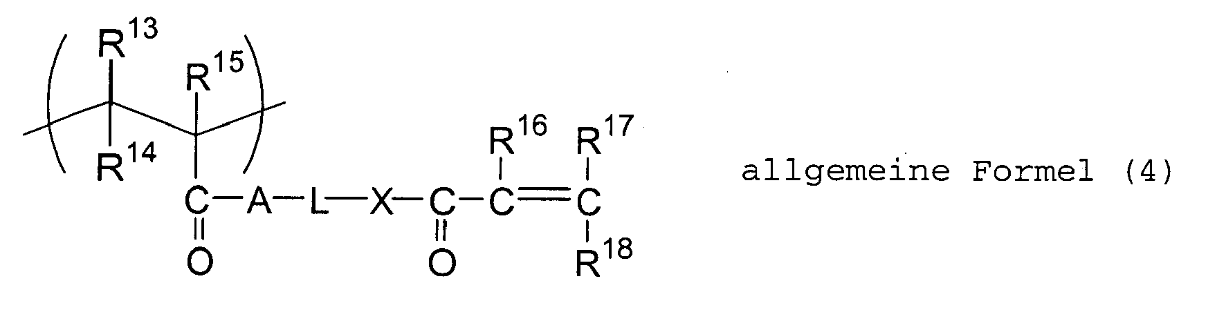

- Negatives Bildaufzeichnungsmaterial vom Wärmemodustyp gemäß Anspruch 1, worin das Bildaufzeichnungsmaterial ferner (D) eine radikalisch polymerisierbare Verbindung umfaßt.
- Negatives Bildaufzeichnungsmaterial vom Wärmemodustyp gemäß Anspruch 1, worin die Polymerverbindung (A) ein Poly(meth)acrylatharz ist.
- Negatives Bildaufzeichnungsmaterial vom Wärmemodustyp gemäß Anspruch 1, worin die Polymerverbindung (A) eine Carbonsäuregruppe in einer Menge von 0,8 bis 1,6 mÄq/g enthält und einen Gewichtsmittelwert des Molekulargewichts von 80.000 bis 180.000 aufweist.
- Negatives Bildaufzeichnungsmaterial vom Wärmemodustyp gemäß Anspruch 1, worin L und M in den allgemeinen Formeln (4) und (5) jeweils unabhängig eine lineare Alkylengruppe darstellen.
- Negatives Bildaufzeichnungsmaterial vom Wärmemodustyp gemäß Anspruch 1, worin das photothermische Umwandlungsmittel (B) ein Cyaninfarbstoff ist.
- Negatives Bildaufzeichnungsmaterial vom Wärmemodustyp gemäß Anspruch 1, worin die Radikale bildende Verbindung (C') eine Oniumsalzverbindung ist.
- Negatives Bildaufzeichnungsmaterial vom Wärmemodustyp gemäß Anspruch 1, worin die Radikale bildende Verbindung (C') eine Sulfoniumsalzverbindung ist.
- Lithographisches Druckplattenoriginal, das folgendes umfaßt:einen Träger undein auf dem Träger bereitgestelltes negatives Bildaufzeichnungsmaterial vom Wärmemodustyp, worin das negative Bildaufzeichnungsmaterial vom Wärmemodustyp wie in Anspruch 1 definiert ist.
- Verfahren zur Herstellung eines Bildes auf einer lithographischen Druckplatte, das die folgenden Schritte umfaßt:(a) Bilden eines negativen Bildaufzeichnungsmaterials vom Wärmemodustyp wie in Anspruch 1 definiert,(b) Anordnen des negativen Bildaufzeichnungsmaterials vom Wärmemodustyp auf einem Träger zur Bildung eines lithographischen Druckplattenoriginals,(c) Belichten des lithographischen Druckplattenoriginals mit einem Infrarotlaser zur Bildung eines latenten Bildes und(d) Bilden eines Bildes unter Verwendung einer alkalischen wäßrigen Lösung zur Entwicklung des latenten Bildes.
Applications Claiming Priority (5)
| Application Number | Priority Date | Filing Date | Title |
|---|---|---|---|
| JP2000249569A JP2002062648A (ja) | 2000-08-21 | 2000-08-21 | 画像記録材料 |
| JP2000249569 | 2000-08-21 | ||
| JP2001030043A JP4199426B2 (ja) | 2001-02-06 | 2001-02-06 | ヒートモード対応ネガ型画像記録材料、及び平版印刷版原版 |
| JP2001030043 | 2001-02-06 | ||
| EP01119647A EP1182033B1 (de) | 2000-08-21 | 2001-08-21 | Bildaufzeichnungsmaterial |
Related Parent Applications (1)
| Application Number | Title | Priority Date | Filing Date |
|---|---|---|---|
| EP01119647A Division EP1182033B1 (de) | 2000-08-21 | 2001-08-21 | Bildaufzeichnungsmaterial |
Publications (2)
| Publication Number | Publication Date |
|---|---|
| EP1563991A1 EP1563991A1 (de) | 2005-08-17 |
| EP1563991B1 true EP1563991B1 (de) | 2007-05-23 |
Family
ID=26598146
Family Applications (2)
| Application Number | Title | Priority Date | Filing Date |
|---|---|---|---|
| EP05010866A Expired - Lifetime EP1563991B1 (de) | 2000-08-21 | 2001-08-21 | Bildaufzeichnungsmaterial |
| EP01119647A Revoked EP1182033B1 (de) | 2000-08-21 | 2001-08-21 | Bildaufzeichnungsmaterial |
Family Applications After (1)
| Application Number | Title | Priority Date | Filing Date |
|---|---|---|---|
| EP01119647A Revoked EP1182033B1 (de) | 2000-08-21 | 2001-08-21 | Bildaufzeichnungsmaterial |
Country Status (4)
| Country | Link |
|---|---|
| US (2) | US6916595B2 (de) |
| EP (2) | EP1563991B1 (de) |
| AT (2) | ATE345928T1 (de) |
| DE (2) | DE60128602T2 (de) |
Families Citing this family (119)
| Publication number | Priority date | Publication date | Assignee | Title |
|---|---|---|---|---|
| US6660446B2 (en) * | 2000-05-30 | 2003-12-09 | Fuji Photo Film Co., Ltd. | Heat-sensitive composition and planographic printing plate |
| ATE345928T1 (de) | 2000-08-21 | 2006-12-15 | Fuji Photo Film Co Ltd | Bildaufzeichnungsmaterial |
| JP2002072462A (ja) * | 2000-08-25 | 2002-03-12 | Fuji Photo Film Co Ltd | 平版印刷版原版及びその製版方法 |
| JP4248137B2 (ja) * | 2000-11-22 | 2009-04-02 | 富士フイルム株式会社 | ネガ型感光性平版印刷版 |
| JP4512281B2 (ja) * | 2001-02-22 | 2010-07-28 | 富士フイルム株式会社 | ネガ型平版印刷版原版 |
| JP4266077B2 (ja) | 2001-03-26 | 2009-05-20 | 富士フイルム株式会社 | 平版印刷版原版及び平版印刷方法 |
| US6702437B2 (en) | 2001-08-23 | 2004-03-09 | Fuji Photo Film Co., Ltd. | Image recording material |
| JP2003302770A (ja) * | 2002-02-08 | 2003-10-24 | Fuji Photo Film Co Ltd | 画像形成方法 |
| JP2004012706A (ja) * | 2002-06-05 | 2004-01-15 | Fuji Photo Film Co Ltd | 平版印刷版原版 |
| KR101001936B1 (ko) * | 2002-06-07 | 2010-12-17 | 후지필름 가부시키가이샤 | 염료 함유 경화성 조성물, 컬러필터 및 그 제조방법 |
| US7569328B2 (en) | 2002-08-16 | 2009-08-04 | Fujifilm Corporation | Resin composition and thermo/photosensitive composition |
| JP4090307B2 (ja) * | 2002-08-22 | 2008-05-28 | 富士フイルム株式会社 | 平版印刷版の作製方法 |
| US20040048195A1 (en) * | 2002-09-04 | 2004-03-11 | Agfa-Gevaert | Heat-sensitive lithographic printing plate precursor |
| JP4137577B2 (ja) | 2002-09-30 | 2008-08-20 | 富士フイルム株式会社 | 感光性組成物 |
| EP1857276A3 (de) | 2002-09-30 | 2007-12-05 | FUJIFILM Corporation | Flachdruckplattenvorläufer |
| JP2004126050A (ja) * | 2002-09-30 | 2004-04-22 | Fuji Photo Film Co Ltd | 平版印刷版原版 |
| CN100590525C (zh) * | 2002-12-18 | 2010-02-17 | 富士胶片株式会社 | 可聚合组合物和平版印刷版前体 |
| JP4150261B2 (ja) | 2003-01-14 | 2008-09-17 | 富士フイルム株式会社 | 平版印刷版原版の製版方法 |
| JP2004252201A (ja) | 2003-02-20 | 2004-09-09 | Fuji Photo Film Co Ltd | 平版印刷版原版 |
| JP4048134B2 (ja) * | 2003-02-21 | 2008-02-13 | 富士フイルム株式会社 | 平版印刷版原版 |
| JP4048133B2 (ja) * | 2003-02-21 | 2008-02-13 | 富士フイルム株式会社 | 感光性組成物及びそれを用いた平版印刷版原版 |
| JP2004252285A (ja) * | 2003-02-21 | 2004-09-09 | Fuji Photo Film Co Ltd | 感光性組成物及びそれを用いた平版印刷版原版 |
| US7060409B2 (en) | 2003-03-10 | 2006-06-13 | Eastman Kodak Company | Imageable elements with improved dot stability |
| US7368215B2 (en) | 2003-05-12 | 2008-05-06 | Eastman Kodak Company | On-press developable IR sensitive printing plates containing an onium salt initiator system |
| JP2005014348A (ja) | 2003-06-25 | 2005-01-20 | Fuji Photo Film Co Ltd | 平版印刷版原版及び平版印刷方法 |
| US7179582B2 (en) * | 2003-07-28 | 2007-02-20 | Fuji Photo Film Co., Ltd. | Radical polymerizable composition and lithographic printing plate precursor using the same |
| JP4299639B2 (ja) | 2003-07-29 | 2009-07-22 | 富士フイルム株式会社 | 重合性組成物及びそれを用いた画像記録材料 |
| JP2005099284A (ja) * | 2003-09-24 | 2005-04-14 | Fuji Photo Film Co Ltd | 感光性組成物及び平版印刷版原版 |
| JP2005326493A (ja) * | 2004-05-12 | 2005-11-24 | Fuji Photo Film Co Ltd | 光重合性平版印刷版の製造方法 |
| US7198834B2 (en) * | 2005-03-22 | 2007-04-03 | Hewlett-Packard Development Company, L.P. | Imaging media including interference layer for generating human-readable marking on optical media |
| US20070065749A1 (en) * | 2005-09-21 | 2007-03-22 | Vladek Kasperchik | Radiation-markable coatings for printing and imaging |
| US20070086308A1 (en) * | 2005-10-13 | 2007-04-19 | Gore Makarand P | Systems and methods for imaging |
| US7935471B2 (en) * | 2005-10-20 | 2011-05-03 | Hewlett-Packard Development Company, L.P. | NIR/IR curable coatings for light directed imaging |
| US20070092827A1 (en) * | 2005-10-20 | 2007-04-26 | Gore Makarand P | Inks for use on light-activated imaging media |
| JP4668111B2 (ja) * | 2005-12-26 | 2011-04-13 | 富士フイルム株式会社 | 重合性組成物及びそれを用いた平版印刷版原版 |
| US7279255B2 (en) | 2006-02-07 | 2007-10-09 | Eastman Kodak Company | Negative-working radiation-sensitive compositions and imageable materials |
| WO2007111996A2 (en) * | 2006-03-24 | 2007-10-04 | Clemson University | Conducting polymer ink |
| US7524614B2 (en) | 2006-05-26 | 2009-04-28 | Eastman Kodak Company | Negative-working radiation-sensitive compositions and imageable materials |
| US7226709B1 (en) | 2006-06-20 | 2007-06-05 | Eastman Kodak Company | Digital mask-forming film and method of use |
| US7332253B1 (en) | 2006-07-27 | 2008-02-19 | Eastman Kodak Company | Negative-working radiation-sensitive compositions and imageable materials |
| US7862984B2 (en) | 2007-03-28 | 2011-01-04 | Eastman Kodak Company | Polyonium borates and radiation-sensitive composition and imageable elements containing same |
| US20080254387A1 (en) * | 2007-04-13 | 2008-10-16 | Jianfei Yu | Negative-working imageable elements and methods of use |
| US7732118B2 (en) * | 2007-05-10 | 2010-06-08 | Eastman Kodak Company | Negative-working imageable elements and methods of use |
| US7781143B2 (en) | 2007-05-31 | 2010-08-24 | Eastman Kodak Company | Negative-working imageable elements and methods of use |
| US7799504B2 (en) | 2007-06-05 | 2010-09-21 | Eastman Kodak Company | Mask film to form relief images and method of use |
| US7763413B2 (en) | 2007-10-16 | 2010-07-27 | Eastman Kodak Company | Methods for imaging and processing negative-working imageable elements |
| JP5089422B2 (ja) * | 2008-02-15 | 2012-12-05 | 岡本化学工業株式会社 | 感光性組成物およびそれを用いた平版印刷版用原版 |
| EP2098367A1 (de) | 2008-03-05 | 2009-09-09 | Eastman Kodak Company | Sensibilisator/Initiator-Kombination für negativ arbeitende wärmeempfindliche Zusammensetzungen für Lithografieplatten |
| US8084182B2 (en) | 2008-04-29 | 2011-12-27 | Eastman Kodak Company | On-press developable elements and methods of use |
| US20100151385A1 (en) | 2008-12-17 | 2010-06-17 | Ray Kevin B | Stack of negative-working imageable elements |
| US8034538B2 (en) | 2009-02-13 | 2011-10-11 | Eastman Kodak Company | Negative-working imageable elements |
| US20100215919A1 (en) | 2009-02-20 | 2010-08-26 | Ting Tao | On-press developable imageable elements |
| US20100227269A1 (en) | 2009-03-04 | 2010-09-09 | Simpson Christopher D | Imageable elements with colorants |
| US8318405B2 (en) | 2009-03-13 | 2012-11-27 | Eastman Kodak Company | Negative-working imageable elements with overcoat |
| US8247163B2 (en) | 2009-06-12 | 2012-08-21 | Eastman Kodak Company | Preparing lithographic printing plates with enhanced contrast |
| US8257907B2 (en) | 2009-06-12 | 2012-09-04 | Eastman Kodak Company | Negative-working imageable elements |
| US8383319B2 (en) | 2009-08-25 | 2013-02-26 | Eastman Kodak Company | Lithographic printing plate precursors and stacks |
| US8426104B2 (en) | 2009-10-08 | 2013-04-23 | Eastman Kodak Company | Negative-working imageable elements |
| US8936899B2 (en) | 2012-09-04 | 2015-01-20 | Eastman Kodak Company | Positive-working lithographic printing plate precursors and use |
| US20110097666A1 (en) | 2009-10-27 | 2011-04-28 | Celin Savariar-Hauck | Lithographic printing plate precursors |
| UA105045C2 (uk) | 2009-10-29 | 2014-04-10 | Майлен Груп | Галотаніни для покривних композицій офсетної друкарської форми |
| US8329383B2 (en) | 2009-11-05 | 2012-12-11 | Eastman Kodak Company | Negative-working lithographic printing plate precursors |
| US20110236832A1 (en) | 2010-03-26 | 2011-09-29 | Celin Savariar-Hauck | Lithographic processing solutions and methods of use |
| US8900798B2 (en) | 2010-10-18 | 2014-12-02 | Eastman Kodak Company | On-press developable lithographic printing plate precursors |
| US20120090486A1 (en) | 2010-10-18 | 2012-04-19 | Celin Savariar-Hauck | Lithographic printing plate precursors and methods of use |
| US20120141941A1 (en) | 2010-12-03 | 2012-06-07 | Mathias Jarek | Developing lithographic printing plate precursors in simple manner |
| US20120141942A1 (en) | 2010-12-03 | 2012-06-07 | Domenico Balbinot | Method of preparing lithographic printing plates |
| US20120141935A1 (en) | 2010-12-03 | 2012-06-07 | Bernd Strehmel | Developer and its use to prepare lithographic printing plates |
| US20120199028A1 (en) | 2011-02-08 | 2012-08-09 | Mathias Jarek | Preparing lithographic printing plates |
| JP5705584B2 (ja) | 2011-02-24 | 2015-04-22 | 富士フイルム株式会社 | 平版印刷版の製版方法 |
| US8530142B2 (en) | 2011-03-15 | 2013-09-10 | Eastman Kodak Company | Flexographic printing plate precursor, imaging assembly, and use |
| EP2693270B1 (de) | 2011-03-28 | 2015-12-09 | FUJIFILM Corporation | Verfahren zur herstellung einer lithografiedruckplatte |
| US8632940B2 (en) | 2011-04-19 | 2014-01-21 | Eastman Kodak Company | Aluminum substrates and lithographic printing plate precursors |
| JP5829177B2 (ja) | 2011-07-12 | 2015-12-09 | 富士フイルム株式会社 | インプリント用硬化性組成物、パターン形成方法およびパターン |
| US8722308B2 (en) | 2011-08-31 | 2014-05-13 | Eastman Kodak Company | Aluminum substrates and lithographic printing plate precursors |
| US8703381B2 (en) | 2011-08-31 | 2014-04-22 | Eastman Kodak Company | Lithographic printing plate precursors for on-press development |
| US9029063B2 (en) | 2011-09-22 | 2015-05-12 | Eastman Kodak Company | Negative-working lithographic printing plate precursors |
| US8632941B2 (en) | 2011-09-22 | 2014-01-21 | Eastman Kodak Company | Negative-working lithographic printing plate precursors with IR dyes |
| WO2013047229A1 (ja) | 2011-09-26 | 2013-04-04 | 富士フイルム株式会社 | 平版印刷版の製版方法 |
| CN103827749B (zh) | 2011-09-26 | 2018-06-15 | 富士胶片株式会社 | 平版印刷版的制版方法 |
| US20130255515A1 (en) | 2012-03-27 | 2013-10-03 | Celin Savariar-Hauck | Positive-working lithographic printing plate precursors |
| US8679726B2 (en) | 2012-05-29 | 2014-03-25 | Eastman Kodak Company | Negative-working lithographic printing plate precursors |
| US8889341B2 (en) | 2012-08-22 | 2014-11-18 | Eastman Kodak Company | Negative-working lithographic printing plate precursors and use |
| US8927197B2 (en) | 2012-11-16 | 2015-01-06 | Eastman Kodak Company | Negative-working lithographic printing plate precursors |
| EP2735903B1 (de) | 2012-11-22 | 2019-02-27 | Eastman Kodak Company | Negativ arbeitende Lithografiedruckplattenvorläufer mit hochverzweigtem Bindemittelmaterial |
| CN103012652B (zh) | 2012-12-14 | 2014-12-17 | 京东方科技集团股份有限公司 | 含有乙烯基醚基团的共聚物及其制备方法和应用 |
| US9063423B2 (en) | 2013-02-28 | 2015-06-23 | Eastman Kodak Company | Lithographic printing plate precursors and use |
| EP2778782B1 (de) | 2013-03-13 | 2015-12-30 | Kodak Graphic Communications GmbH | Negativ arbeitende strahlungsempfindliche Elemente |
| US8945813B2 (en) | 2013-04-18 | 2015-02-03 | Eastman Kodak Company | Mask forming imageable material and use |
| JP6029558B2 (ja) * | 2013-09-30 | 2016-11-24 | 富士フイルム株式会社 | 光インプリント用硬化性組成物、パターン形成方法、微細パターン、および半導体デバイスの製造方法 |
| US9201302B2 (en) | 2013-10-03 | 2015-12-01 | Eastman Kodak Company | Negative-working lithographic printing plate precursor |
| EP3064192B1 (de) | 2015-03-06 | 2018-11-07 | Ivoclar Vivadent AG | Dentalmaterialien auf der Basis von Hybridmonomeren |
| US20170021656A1 (en) | 2015-07-24 | 2017-01-26 | Kevin Ray | Lithographic imaging and printing with negative-working photoresponsive printing members |
| US9588429B1 (en) | 2015-09-03 | 2017-03-07 | Eastman Kodak Company | Lithographic developer composition and method of use |
| US20170217149A1 (en) | 2016-01-28 | 2017-08-03 | Eastman Kodak Company | Negatively-working lithographic printing plate precursor and method |
| CN106313870B (zh) | 2016-08-19 | 2018-06-15 | 浙江康尔达新材料股份有限公司 | 一种可成像涂层、热敏阴图平版印刷版及其制版方法 |
| US20180157176A1 (en) | 2016-12-02 | 2018-06-07 | Eastman Kodak Company | Lithographic printing plate precursor and use |
| WO2018128830A1 (en) | 2017-01-04 | 2018-07-12 | Eastman Kodak Company | Negative-working lithographic printing plate precursor and use |
| US10828884B2 (en) | 2017-03-02 | 2020-11-10 | Eastman Kodak Company | Lithographic printing plate precursors and method of use |
| US10576730B2 (en) | 2017-07-19 | 2020-03-03 | Eastman Kodak Company | Method for preparing lithographic printing plates |
| DK3752885T3 (da) | 2018-02-16 | 2024-10-28 | Miraclon Corp | Maskeelementforløber og reliefbilleddannelsessystem |
| US20200096865A1 (en) | 2018-09-21 | 2020-03-26 | Eastman Kodak Company | Lithographic printing plate precursor and color-forming composition |
| US20210078350A1 (en) | 2019-09-17 | 2021-03-18 | Eastman Kodak Company | Lithographic printing plate precursor and method of use |
| US11117412B2 (en) | 2019-10-01 | 2021-09-14 | Eastman Kodak Company | Lithographic printing plate precursors and method of use |
| US11633948B2 (en) | 2020-01-22 | 2023-04-25 | Eastman Kodak Company | Method for making lithographic printing plates |
| US11714354B2 (en) | 2020-03-25 | 2023-08-01 | Eastman Kodak Company | Lithographic printing plate precursor and method of use |
| US11760081B2 (en) | 2020-09-04 | 2023-09-19 | Eastman Kodak Company | Lithographic printing plate precursor and method of use |
| JP2023553000A (ja) | 2020-12-04 | 2023-12-20 | イーストマン コダック カンパニー | 平版印刷版原版および使用方法 |
| CN116615339B (zh) | 2020-12-17 | 2025-10-10 | 伊斯曼柯达公司 | 平版印刷版前体和使用方法 |
| WO2022212032A1 (en) | 2021-04-01 | 2022-10-06 | Eastman Kodak Company | Lithographic printing plate precursor and method of use |
| EP4101830A1 (de) | 2021-06-10 | 2022-12-14 | FEW Chemicals GmbH | Neuartige diaryliodoniumsalzmischungen als photoinitiatoren mit niedrigem molekulargewicht und minimierter kristallisierung und erhöhter löslichkeit |
| US20230091079A1 (en) | 2021-07-23 | 2023-03-23 | Eastman Kodak Company | Lithographic printing plate precursor and method of use |
| CN113942289B (zh) | 2021-10-26 | 2023-02-28 | 浙江康尔达新材料股份有限公司 | 一种用于光敏阴图型平版印刷版的可成像组合物及其制版方法 |
| US12222645B2 (en) | 2022-03-03 | 2025-02-11 | Eastman Kodak Company | Lithographic printing plate precursor and method of use |
| US12474639B2 (en) | 2022-04-27 | 2025-11-18 | Miraclon Corporation | Flexographic printing mask with laser thermal imaging film |
| US12496846B2 (en) | 2022-06-16 | 2025-12-16 | Miraclon Corporation | Mask for low contrast printed highlights |
| US12429774B2 (en) | 2022-08-04 | 2025-09-30 | Eastman Kodak Company | Lithographic printing plate precursors, methods of using and manufacture |
| US20240069439A1 (en) | 2022-08-12 | 2024-02-29 | Eastman Kodak Company | Lithographic printing plate precursor and method of use |
| US12429770B2 (en) | 2023-06-27 | 2025-09-30 | Eastman Kodak Company | Lithographic printing plate precursor and method of use |
Citations (1)
| Publication number | Priority date | Publication date | Assignee | Title |
|---|---|---|---|---|
| EP0761429A1 (de) * | 1995-07-31 | 1997-03-12 | Fuji Photo Film Co., Ltd. | Negativarbeitendes Bildaufzeichnungsmaterial |
Family Cites Families (40)
| Publication number | Priority date | Publication date | Assignee | Title |
|---|---|---|---|---|
| US4710445A (en) * | 1986-04-22 | 1987-12-01 | Minnesota Mining And Manufacturing Company | Resist imageable photopolymerizable compositions |
| US5043396A (en) | 1988-12-28 | 1991-08-27 | Nippon Zeon Co., Ltd. | Novel crosslinked polymer having shape memorizing property, method of its use, and molded article having shape memory |
| JPH061088A (ja) | 1992-06-17 | 1994-01-11 | Canon Inc | 印刷用原版、それを用いた印刷版の製造方法、その印刷版を用いた印刷方法及び印刷装置 |
| JPH08108621A (ja) | 1994-10-06 | 1996-04-30 | Konica Corp | 画像記録媒体及びそれを用いる画像形成方法 |
| JPH0934110A (ja) | 1995-07-17 | 1997-02-07 | Konica Corp | 光重合性組成物、ラジカル発生方法、平版印刷版作成用感光材料及びそれを用いた平版印刷版の作成方法 |
| JPH0943847A (ja) | 1995-07-31 | 1997-02-14 | Dainippon Printing Co Ltd | レジスト材及びパターン形成方法 |
| IL118550A0 (en) * | 1996-06-03 | 1996-10-16 | Scitex Corp Ltd | A recording film for producing a printing plate therefrom |
| JP3798504B2 (ja) * | 1997-04-21 | 2006-07-19 | 富士写真フイルム株式会社 | ネガ型画像記録材料 |
| CA2245304C (en) | 1997-08-20 | 2007-03-06 | Toray Industries, Inc. | A directly imageable waterless planographic printing plate |
| JP3810538B2 (ja) | 1997-11-28 | 2006-08-16 | 富士写真フイルム株式会社 | ポジ型画像形成材料 |
| US6153356A (en) | 1998-08-17 | 2000-11-28 | Mitsubishi Chemical Corporation | Photopolymerizable composition, photopolymerizable lithographic printing plate and process for forming an image |
| JP4037015B2 (ja) | 1999-09-22 | 2008-01-23 | 富士フイルム株式会社 | 光重合性組成物、画像形成材料及び平版印刷版用版材 |
| JP3948505B2 (ja) | 1999-10-27 | 2007-07-25 | 富士フイルム株式会社 | 平版印刷版用原版 |
| US6566035B1 (en) * | 1999-10-29 | 2003-05-20 | Fuji Photo Film Co., Ltd. | Negative-type image recording material and precursor for negative-type lithographic printing plate |
| JP2001133969A (ja) | 1999-11-01 | 2001-05-18 | Fuji Photo Film Co Ltd | ネガ型平版印刷版原版 |
| JP4050854B2 (ja) | 1999-12-21 | 2008-02-20 | 富士フイルム株式会社 | 画像形成方法 |
| US6309792B1 (en) * | 2000-02-18 | 2001-10-30 | Kodak Polychrome Graphics Llc | IR-sensitive composition and use thereof for the preparation of printing plate precursors |
| JP2001312062A (ja) | 2000-05-02 | 2001-11-09 | Fuji Photo Film Co Ltd | 画像記録材料 |
| US6692896B2 (en) * | 2000-03-01 | 2004-02-17 | Fuji Photo Film Co., Ltd. | Heat mode-compatible planographic printing plate |
| ATE395185T1 (de) | 2000-03-01 | 2008-05-15 | Fujifilm Corp | Bildaufzeichnungsmaterial |
| US6660446B2 (en) * | 2000-05-30 | 2003-12-09 | Fuji Photo Film Co., Ltd. | Heat-sensitive composition and planographic printing plate |
| JP4335416B2 (ja) | 2000-06-06 | 2009-09-30 | 富士フイルム株式会社 | 画像形成材料及び赤外線吸収色素 |
| JP2002023350A (ja) * | 2000-07-07 | 2002-01-23 | Fuji Photo Film Co Ltd | ネガ型平版印刷版原版 |
| JP4156784B2 (ja) | 2000-07-25 | 2008-09-24 | 富士フイルム株式会社 | ネガ型画像記録材料及び画像形成方法 |
| ATE345928T1 (de) | 2000-08-21 | 2006-12-15 | Fuji Photo Film Co Ltd | Bildaufzeichnungsmaterial |
| JP2002072462A (ja) * | 2000-08-25 | 2002-03-12 | Fuji Photo Film Co Ltd | 平版印刷版原版及びその製版方法 |
| JP2002082429A (ja) | 2000-09-08 | 2002-03-22 | Fuji Photo Film Co Ltd | ネガ型画像記録材料 |
| EP1211096A1 (de) | 2000-12-01 | 2002-06-05 | Fuji Photo Film Co., Ltd. | Trägermaterial für lithographische Druckplatte und dieses verwendende lithographische Druckplatte |
| JP2002251008A (ja) * | 2001-02-23 | 2002-09-06 | Fuji Photo Film Co Ltd | 画像記録材料 |
| JP4266077B2 (ja) * | 2001-03-26 | 2009-05-20 | 富士フイルム株式会社 | 平版印刷版原版及び平版印刷方法 |
| US6410208B1 (en) * | 2001-04-18 | 2002-06-25 | Gary Ganghui Teng | Lithographic printing plates having a thermo-deactivatable photosensitive layer |
| JP2003057830A (ja) | 2001-08-15 | 2003-02-28 | Fuji Photo Film Co Ltd | 平版印刷版原版 |
| US6702437B2 (en) * | 2001-08-23 | 2004-03-09 | Fuji Photo Film Co., Ltd. | Image recording material |
| US6890701B2 (en) | 2001-09-11 | 2005-05-10 | Fuji Photo Film Co., Ltd. | Photopolymerizable composition |
| EP1332870A3 (de) | 2002-02-05 | 2005-01-12 | Fuji Photo Film Co., Ltd. | Infrarot-empfindliche Zusammensetzung |
| JP2003302770A (ja) | 2002-02-08 | 2003-10-24 | Fuji Photo Film Co Ltd | 画像形成方法 |
| JP2003252939A (ja) | 2002-03-01 | 2003-09-10 | Fuji Photo Film Co Ltd | 光重合性組成物 |
| ATE431366T1 (de) * | 2002-03-11 | 2009-05-15 | Fujifilm Corp | Verfahren zur herstellung von polymerverbindungen durch eliminierungsreaktion |
| EP1369231A3 (de) * | 2002-06-05 | 2009-07-08 | FUJIFILM Corporation | Infrarotempfindliche Zusammensetzung und Bildaufzeichnungsmaterial für IR-Strahlung |
| JP2004012706A (ja) * | 2002-06-05 | 2004-01-15 | Fuji Photo Film Co Ltd | 平版印刷版原版 |
-
2001
- 2001-08-21 AT AT01119647T patent/ATE345928T1/de not_active IP Right Cessation
- 2001-08-21 US US09/932,975 patent/US6916595B2/en not_active Expired - Lifetime
- 2001-08-21 DE DE60128602T patent/DE60128602T2/de not_active Expired - Lifetime
- 2001-08-21 EP EP05010866A patent/EP1563991B1/de not_active Expired - Lifetime
- 2001-08-21 AT AT05010866T patent/ATE362846T1/de not_active IP Right Cessation
- 2001-08-21 DE DE60124635T patent/DE60124635T2/de not_active Expired - Lifetime
- 2001-08-21 EP EP01119647A patent/EP1182033B1/de not_active Revoked
-
2005
- 2005-03-01 US US11/067,698 patent/US7105276B2/en not_active Expired - Lifetime
Patent Citations (1)
| Publication number | Priority date | Publication date | Assignee | Title |
|---|---|---|---|---|
| EP0761429A1 (de) * | 1995-07-31 | 1997-03-12 | Fuji Photo Film Co., Ltd. | Negativarbeitendes Bildaufzeichnungsmaterial |
Also Published As
| Publication number | Publication date |
|---|---|
| US7105276B2 (en) | 2006-09-12 |
| ATE362846T1 (de) | 2007-06-15 |
| EP1182033B1 (de) | 2006-11-22 |
| DE60124635T2 (de) | 2007-09-13 |
| EP1563991A1 (de) | 2005-08-17 |
| US20050187103A1 (en) | 2005-08-25 |
| US20030008239A1 (en) | 2003-01-09 |
| DE60128602D1 (de) | 2007-07-05 |
| US6916595B2 (en) | 2005-07-12 |
| DE60124635D1 (de) | 2007-01-04 |
| ATE345928T1 (de) | 2006-12-15 |
| EP1182033A1 (de) | 2002-02-27 |
| DE60128602T2 (de) | 2008-01-31 |
Similar Documents
| Publication | Publication Date | Title |
|---|---|---|
| EP1563991B1 (de) | Bildaufzeichnungsmaterial | |
| EP1186407B1 (de) | Negatives Bildaufzeichnungsmaterial | |
| JP4295418B2 (ja) | ネガ型平版印刷版原版 | |
| JP4050854B2 (ja) | 画像形成方法 | |
| US6800417B2 (en) | Lithographic printing plate precursor | |
| US6242155B1 (en) | Method of making lithographic printing plate and photopolymer composition | |
| JP4137577B2 (ja) | 感光性組成物 | |
| JP3908569B2 (ja) | 画像記録材料 | |
| JP2001242612A (ja) | 画像記録材料 | |
| JP2001133969A (ja) | ネガ型平版印刷版原版 | |
| EP1467250A2 (de) | Lichtempfindliche Zusammensetzung und lithographischer Druckplattenvorläufer | |
| JP4199426B2 (ja) | ヒートモード対応ネガ型画像記録材料、及び平版印刷版原版 | |
| JP2002062648A (ja) | 画像記録材料 | |
| US6680161B2 (en) | Lithographic printing plate precursor | |
| EP1516725B1 (de) | Flachdruckplattenvorläufer | |
| JP4137367B2 (ja) | 画像記録材料 | |
| JP4160800B2 (ja) | 画像記録材料 | |
| JP4054150B2 (ja) | ネガ型平版印刷版原版 | |
| JP4299550B2 (ja) | 平版印刷版原版 | |
| JP2002090984A (ja) | 平版印刷版原版 | |
| JP2002090985A (ja) | 平版印刷版原版 | |
| JP4141492B2 (ja) | ネガ型平版印刷版原版 | |
| JP3894285B2 (ja) | ネガ型画像形成材料 | |
| JP2004029116A (ja) | 感光性組成物 | |
| JP2006267958A (ja) | 印刷版の保護層の検査方法 |
Legal Events
| Date | Code | Title | Description |
|---|---|---|---|
| PUAI | Public reference made under article 153(3) epc to a published international application that has entered the european phase |
Free format text: ORIGINAL CODE: 0009012 |
|
| AC | Divisional application: reference to earlier application |
Ref document number: 1182033 Country of ref document: EP Kind code of ref document: P |
|
| AK | Designated contracting states |
Kind code of ref document: A1 Designated state(s): AT BE CH CY DE DK ES FI FR GB GR IE IT LI LU MC NL PT SE TR |
|
| 17P | Request for examination filed |
Effective date: 20060117 |
|
| AKX | Designation fees paid |
Designated state(s): AT BE CH CY DE DK ES FI FR GB GR IE IT LI LU MC NL PT SE TR |
|
| GRAP | Despatch of communication of intention to grant a patent |
Free format text: ORIGINAL CODE: EPIDOSNIGR1 |
|
| GRAS | Grant fee paid |
Free format text: ORIGINAL CODE: EPIDOSNIGR3 |
|
| RAP1 | Party data changed (applicant data changed or rights of an application transferred) |
Owner name: FUJIFILM CORPORATION |
|
| GRAA | (expected) grant |
Free format text: ORIGINAL CODE: 0009210 |
|
| AC | Divisional application: reference to earlier application |
Ref document number: 1182033 Country of ref document: EP Kind code of ref document: P |
|
| AK | Designated contracting states |
Kind code of ref document: B1 Designated state(s): AT BE CH CY DE DK ES FI FR GB GR IE IT LI LU MC NL PT SE TR |
|
| PG25 | Lapsed in a contracting state [announced via postgrant information from national office to epo] |
Ref country code: CH Free format text: LAPSE BECAUSE OF FAILURE TO SUBMIT A TRANSLATION OF THE DESCRIPTION OR TO PAY THE FEE WITHIN THE PRESCRIBED TIME-LIMIT Effective date: 20070523 Ref country code: FI Free format text: LAPSE BECAUSE OF FAILURE TO SUBMIT A TRANSLATION OF THE DESCRIPTION OR TO PAY THE FEE WITHIN THE PRESCRIBED TIME-LIMIT Effective date: 20070523 Ref country code: LI Free format text: LAPSE BECAUSE OF FAILURE TO SUBMIT A TRANSLATION OF THE DESCRIPTION OR TO PAY THE FEE WITHIN THE PRESCRIBED TIME-LIMIT Effective date: 20070523 |
|
| REG | Reference to a national code |
Ref country code: GB Ref legal event code: FG4D |
|
| REG | Reference to a national code |
Ref country code: CH Ref legal event code: EP |
|
| REG | Reference to a national code |
Ref country code: IE Ref legal event code: FG4D |
|
| REF | Corresponds to: |
Ref document number: 60128602 Country of ref document: DE Date of ref document: 20070705 Kind code of ref document: P |
|
| PG25 | Lapsed in a contracting state [announced via postgrant information from national office to epo] |
Ref country code: SE Free format text: LAPSE BECAUSE OF FAILURE TO SUBMIT A TRANSLATION OF THE DESCRIPTION OR TO PAY THE FEE WITHIN THE PRESCRIBED TIME-LIMIT Effective date: 20070823 |
|
| PG25 | Lapsed in a contracting state [announced via postgrant information from national office to epo] |
Ref country code: ES Free format text: LAPSE BECAUSE OF FAILURE TO SUBMIT A TRANSLATION OF THE DESCRIPTION OR TO PAY THE FEE WITHIN THE PRESCRIBED TIME-LIMIT Effective date: 20070903 |
|
| NLV1 | Nl: lapsed or annulled due to failure to fulfill the requirements of art. 29p and 29m of the patents act | ||
| PG25 | Lapsed in a contracting state [announced via postgrant information from national office to epo] |
Ref country code: AT Free format text: LAPSE BECAUSE OF FAILURE TO SUBMIT A TRANSLATION OF THE DESCRIPTION OR TO PAY THE FEE WITHIN THE PRESCRIBED TIME-LIMIT Effective date: 20070523 |
|
| REG | Reference to a national code |
Ref country code: CH Ref legal event code: PL |
|
| PG25 | Lapsed in a contracting state [announced via postgrant information from national office to epo] |
Ref country code: BE Free format text: LAPSE BECAUSE OF FAILURE TO SUBMIT A TRANSLATION OF THE DESCRIPTION OR TO PAY THE FEE WITHIN THE PRESCRIBED TIME-LIMIT Effective date: 20070523 |
|
| EN | Fr: translation not filed | ||
| PG25 | Lapsed in a contracting state [announced via postgrant information from national office to epo] |
Ref country code: PT Free format text: LAPSE BECAUSE OF FAILURE TO SUBMIT A TRANSLATION OF THE DESCRIPTION OR TO PAY THE FEE WITHIN THE PRESCRIBED TIME-LIMIT Effective date: 20071023 Ref country code: DK Free format text: LAPSE BECAUSE OF FAILURE TO SUBMIT A TRANSLATION OF THE DESCRIPTION OR TO PAY THE FEE WITHIN THE PRESCRIBED TIME-LIMIT Effective date: 20070523 Ref country code: NL Free format text: LAPSE BECAUSE OF FAILURE TO SUBMIT A TRANSLATION OF THE DESCRIPTION OR TO PAY THE FEE WITHIN THE PRESCRIBED TIME-LIMIT Effective date: 20070523 |
|
| PLBE | No opposition filed within time limit |
Free format text: ORIGINAL CODE: 0009261 |
|
| STAA | Information on the status of an ep patent application or granted ep patent |
Free format text: STATUS: NO OPPOSITION FILED WITHIN TIME LIMIT |
|
| 26N | No opposition filed |
Effective date: 20080226 |
|
| PG25 | Lapsed in a contracting state [announced via postgrant information from national office to epo] |
Ref country code: GR Free format text: LAPSE BECAUSE OF FAILURE TO SUBMIT A TRANSLATION OF THE DESCRIPTION OR TO PAY THE FEE WITHIN THE PRESCRIBED TIME-LIMIT Effective date: 20070824 Ref country code: MC Free format text: LAPSE BECAUSE OF NON-PAYMENT OF DUE FEES Effective date: 20070831 Ref country code: IT Free format text: LAPSE BECAUSE OF FAILURE TO SUBMIT A TRANSLATION OF THE DESCRIPTION OR TO PAY THE FEE WITHIN THE PRESCRIBED TIME-LIMIT Effective date: 20070523 |
|
| PG25 | Lapsed in a contracting state [announced via postgrant information from national office to epo] |
Ref country code: FR Free format text: LAPSE BECAUSE OF FAILURE TO SUBMIT A TRANSLATION OF THE DESCRIPTION OR TO PAY THE FEE WITHIN THE PRESCRIBED TIME-LIMIT Effective date: 20080118 |
|
| PG25 | Lapsed in a contracting state [announced via postgrant information from national office to epo] |
Ref country code: IE Free format text: LAPSE BECAUSE OF NON-PAYMENT OF DUE FEES Effective date: 20070821 |
|
| PG25 | Lapsed in a contracting state [announced via postgrant information from national office to epo] |
Ref country code: CY Free format text: LAPSE BECAUSE OF FAILURE TO SUBMIT A TRANSLATION OF THE DESCRIPTION OR TO PAY THE FEE WITHIN THE PRESCRIBED TIME-LIMIT Effective date: 20070523 |
|
| PG25 | Lapsed in a contracting state [announced via postgrant information from national office to epo] |
Ref country code: LU Free format text: LAPSE BECAUSE OF NON-PAYMENT OF DUE FEES Effective date: 20070821 |
|
| PG25 | Lapsed in a contracting state [announced via postgrant information from national office to epo] |
Ref country code: TR Free format text: LAPSE BECAUSE OF FAILURE TO SUBMIT A TRANSLATION OF THE DESCRIPTION OR TO PAY THE FEE WITHIN THE PRESCRIBED TIME-LIMIT Effective date: 20070523 |
|
| PGFP | Annual fee paid to national office [announced via postgrant information from national office to epo] |
Ref country code: GB Payment date: 20200813 Year of fee payment: 20 Ref country code: DE Payment date: 20200812 Year of fee payment: 20 |
|
| REG | Reference to a national code |
Ref country code: DE Ref legal event code: R071 Ref document number: 60128602 Country of ref document: DE |
|
| REG | Reference to a national code |
Ref country code: GB Ref legal event code: PE20 Expiry date: 20210820 |
|
| PG25 | Lapsed in a contracting state [announced via postgrant information from national office to epo] |
Ref country code: GB Free format text: LAPSE BECAUSE OF EXPIRATION OF PROTECTION Effective date: 20210820 |