EP1563505B1 - Vorrichtung zum unlesbarmachen von optischen speichermedien - Google Patents
Vorrichtung zum unlesbarmachen von optischen speichermedien Download PDFInfo
- Publication number
- EP1563505B1 EP1563505B1 EP03810987A EP03810987A EP1563505B1 EP 1563505 B1 EP1563505 B1 EP 1563505B1 EP 03810987 A EP03810987 A EP 03810987A EP 03810987 A EP03810987 A EP 03810987A EP 1563505 B1 EP1563505 B1 EP 1563505B1
- Authority
- EP
- European Patent Office
- Prior art keywords
- tips
- slot
- approximately
- optical storage
- recess
- Prior art date
- Legal status (The legal status is an assumption and is not a legal conclusion. Google has not performed a legal analysis and makes no representation as to the accuracy of the status listed.)
- Expired - Lifetime
Links
- 230000003287 optical effect Effects 0.000 title claims abstract description 8
- 238000009877 rendering Methods 0.000 title 1
- 229910000639 Spring steel Inorganic materials 0.000 description 2
- 239000000463 material Substances 0.000 description 2
- 229910000831 Steel Inorganic materials 0.000 description 1
- 238000004026 adhesive bonding Methods 0.000 description 1
- 229910052782 aluminium Inorganic materials 0.000 description 1
- XAGFODPZIPBFFR-UHFFFAOYSA-N aluminium Chemical compound [Al] XAGFODPZIPBFFR-UHFFFAOYSA-N 0.000 description 1
- 229910052751 metal Inorganic materials 0.000 description 1
- 239000002184 metal Substances 0.000 description 1
- 238000000034 method Methods 0.000 description 1
- 239000002904 solvent Substances 0.000 description 1
- 239000010959 steel Substances 0.000 description 1
- 239000002023 wood Substances 0.000 description 1
Images

Classifications
-
- G—PHYSICS
- G11—INFORMATION STORAGE
- G11B—INFORMATION STORAGE BASED ON RELATIVE MOVEMENT BETWEEN RECORD CARRIER AND TRANSDUCER
- G11B23/00—Record carriers not specific to the method of recording or reproducing; Accessories, e.g. containers, specially adapted for co-operation with the recording or reproducing apparatus ; Intermediate mediums; Apparatus or processes specially adapted for their manufacture
- G11B23/50—Reconditioning of record carriers; Cleaning of record carriers ; Carrying-off electrostatic charges
- G11B23/505—Reconditioning of record carriers; Cleaning of record carriers ; Carrying-off electrostatic charges of disk carriers
-
- G—PHYSICS
- G11—INFORMATION STORAGE
- G11B—INFORMATION STORAGE BASED ON RELATIVE MOVEMENT BETWEEN RECORD CARRIER AND TRANSDUCER
- G11B3/00—Recording by mechanical cutting, deforming or pressing, e.g. of grooves or pits; Reproducing by mechanical sensing; Record carriers therefor
- G11B3/66—Erasing information, e.g. for reuse of record carrier
Definitions
- the invention relates to a device for the unreadable of optical storage media, in particular CDs and DVDs.
- CDs are therefore often used to back up information. If the information is no longer needed, it should be deleted. For CDs, this means that they should be made illegible. This is intended to prevent misuse of the stored data.
- JP-A-01053352 it is known to arrange two CDs with the reading sides to each other and to enter between the two CDs a solvent which destroys the layers carrying the information.
- JP 2002 312 945 A disclose devices for unreading optical storage media such as CDs and DVDs with tips.
- the invention has for its object to provide a simple device for unreadable optical storage media such as CDs and DVDs.
- the device has a body with an incision and at least one pair of oppositely directed projecting into the incision tip.
- a CD If a CD is to be made illegible, it is pushed into the incision. The tip (s) protruding into the incision scratches the two surfaces of the CD so that the information stored on the CD can no longer be read.
- At least six oppositely directed tips protrude into the incision, so that a CD pushed into the incision is scratched both on the top and on the underside, three times in each case.
- the tips are ideally arranged so that they can scratch the surface of the CD over the entire radius. A reconstruction of the data contained on the CD is then hardly possible even with great effort.
- the body may be a 25 to 35 mm diameter, 150 mm long rod having at one end an incision at least 1 mm in height extending over a length of at least 50 mm.
- threaded pins are screwed perpendicular to the plane of the incision, and aligned with each other.
- the setscrews are tapered at the front end and are screwed in so far that both tips protrude into the recess and the distance of the tips is smaller than the thickness of a CD, ie at most 0.7 mm.
- the rod may be made of metal (eg aluminum), plastic or wood.
- the set screws are made of a material that is significantly harder than the plastic material of the CDs and DVDs. Preferably, they are steel pins with a hardened tip.
- the grub screws can be secured by gluing or countering or self-locking, before turning in or out - and thus a change in the distance.
- the body is a flat, rectangular plate with side lengths of 10 and 14 cm.
- a flat, pocket-shaped incision is provided whose width is slightly larger than the diameter of a CD and whose depth corresponds approximately to the radius of a CD.
- the mutually directed (ideally 6) set screws are provided in the center. To make them illegible a CD is then one or more times in the pocket-shaped Slit pushed, each time then on both sides of the CD one or more scratches are attached.
- the device is similar to a tuning fork and thus has a cylindrical handle from which two or more prongs or fingers extend forward, which have at their front end against each other directed tips.
- the prongs or fingers are suitably made of spring steel, so that the tips are pressed with the predetermined by the elasticity of the prongs or fingers force in the front and back of a CD.
- the illustrated in the drawing embodiment of the device according to the invention has a body in the form of a rod 10 of round cross-section.
- the length of the rod 10 is 150 mm and the diameter 25-35 mm.
- an incision 12 which extends through the entire diameter of the rod 10 and has a length of 50 to 52 mm.
- coaxial threaded pins 14, 14a and 15 are screwed into corresponding threaded holes in the rod 10 and that at a small distance from the front, in Fig. 1 left end of the rod 10. In the illustrated embodiment, the distance is approximately 5 mm.
- the setscrews 14, 14a and 15 have at the end projecting into the incision 12 a conical tip 16.
- the tips 16 of the coaxial setscrews 14, 14a and 15 are, as seen in Figure 1, facing each other and their distance is about 0, 3 mm less than the thickness of a CD, which is to be made unreadable by means of the device. The two tips protrude equally far into the incision 12.
- the setscrews 14, 14 a and 15 are provided with a hexagon socket.
- Fig. 2 shows the device of Fig. 1 in plan view. It is a second or third pair of grub screws 15 located, which may optionally be present.
- three pairs of threaded pins 14, 14a and 15 are arranged next to one another.
- the cross section of the rod 10 may be round or square or similar.
- the device according to the invention is used in such a way that the optical storage medium, e.g. a CD is inserted into the recess 12 until the edge of the CD touches the end of the incision 12.
- the optical storage medium e.g. a CD
- the tips 16 of the setscrews 14, 14a and 15 both the top and the bottom of the CD is scratched. If at least 6 scratches are made on the CD in this way, the CD is no longer readable with conventional CD drives.
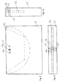
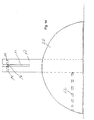
- Figures 8, 9 and 10 show an embodiment in which the body has the shape of a rectangular plate 10 with side lengths of about 110 and 150 mm and a thickness of about 20 mm.
- an approximately 5 mm high incision 12 is provided in the median plane of the plate, which extends nearly the entire length of the page and has a depth of about 55 mm, which is slightly less than the radius of a CD.
- the incision 12 has a trapezoidal plan, but may also be semicircular. Slightly set back from the center of the opening of the recess 12 are screwed on the top and bottom of the plate 10 set screws 14, 14a and 15, the conical tip 16 protrude into the recess 12 and have a mutual distance of at most 0.7 mm.
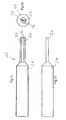
- Figures 11 to 13 show an embodiment in which the device is formed similar to a tuning fork.
- the body is made up of a handle 24 and at least two tines or fingers 26 together, which project from the handle 24 axially parallel to it and parallel to each other.
- the prongs 26 have an oval or round cross section, but may also have a rectangular cross section. Their length is at least 50 mm.
- the tips 16 are formed.
- the tines 26 extend away from a mandrel and consist for example of spring steel.
- Fig. 14 shows a table model of the device according to the invention.
- the rod 10 is inserted into a foot 20 and secured there by means of a threaded pin 22.
- the weight of the foot is sized so that the weight force is greater than the force required to pull the CD out of the recess 12 so that the table model will not be raised when the CD is withdrawn.
Landscapes
- Manufacturing Optical Record Carriers (AREA)
- Automatic Disk Changers (AREA)
- Optical Recording Or Reproduction (AREA)
- Optical Record Carriers And Manufacture Thereof (AREA)
- Holding Or Fastening Of Disk On Rotational Shaft (AREA)
Description
- Die Erfindung betrifft eine Vorrichtung zum Unlesbarmachen von optischen Speichermedien, insbesondere CDs und DVDs.
- Geräte zum Aufzeichnen von Information auf CDs sind allgemein verfügbar. Wegen der geringen Kosten von CD-Rohlingen werden CDs daher häufig zum Sichern von Informationen verwendet. Wenn die Informationen nicht mehr benötigt werden, so sollen sie gelöscht werden. Bei CDs bedeutet dies, dass diese unlesbar gemacht werden sollen. Dadurch soll ein Missbrauch der gespeicherten Daten verhindert werden.
- Aus JP-A-2000222740 ist ein Verfahren zum Entsorgen von CDs bekannt, wobei die CD in eine Folie eingeschweißt wird.
- Aus JP-A-01053352 ist es bekannt, zwei CDs mit den Leseseiten zueinander anzuordnen und zwischen die beiden CDs ein Lösungsmittel einzugeben, das die Schichten zerstört, die die Information tragen.
- Aus DE 100 61 321 A und JP 2002 312 945 A sind Vorrichtungen zum Unlesbarmachen optischer Speichermedien wie CDs und DVDs mit Spitzen bekannt.
- Der Erfindung liegt die Aufgabe zugrunde, eine einfache Vorrichtung zum Unlesbarmachen von optischen Speichermedien wie CDs und DVDs zu schaffen.
- Erfindungsgemäß wird diese Aufgabe dadurch gelöst, dass die Vorrichtung einen Körper mit einem Einschnitt und mindestens ein Paar gegeneinander gerichteter in den Einschnitt ragenden Spitze aufweist.
- Soll eine CD unlesbar gemacht werden, so wird sie in den Einschnitt geschoben. Die in den Einschnitt ragende Spitze(n) zerkratzt die beiden Oberflächen der CD dabei, so dass die auf der CD gespeicherte Information nicht mehr gelesen werden kann.
- Vorzugsweise ragen in den Einschnitt mindestens sechs gegeneinander gerichtete Spitzen, so dass eine in den Einschnitt geschobene CD sowohl auf der Ober- als auch auf der Unterseite -jeweils dreimal- zerkratzt wird. Die Spitzen sind idealerweise so angeordnet, dass sie über den gesamten Radius die Oberfläche der CD zerkratzen können. Ein Rekonstruieren der auf der CD enthaltenen Daten ist dann auch mit großem Aufwand kaum noch möglich.
- Bei dem Körper kann es sich beispielsweise um einen Stab mit 25 bis 35 mm Durchmesser und 150 mm Länge handeln, der an einem Ende einen Einschnitt mit einer Höhe von mindestens 1 mm hat, der sich über eine Länge von mindestens 50 mm erstreckt. Im Abstand von ca. 5 mm von diesem Stabende sind Gewindestifte senkrecht zur Ebene des Einschnitts eingedreht, und gegeneinander ausgerichtet. Die Gewindestifte sind am vorderen Ende zugespitzt und sind so weit eingedreht, dass beide Spitzen in den Einschnitt vorstehen und der Abstand der Spitzen kleiner ist als die Dicke einer CD, also höchstens 0,7 mm.
- Der Stab kann aus Metall (beispielsweise Aluminium), Kunststoff oder Holz bestehen. Die Gewindestifte bestehen aus einem Material, das deutlich härter ist als das Kunststoffmaterial der CDs und DVDs. Vorzugsweise handelt es sich um Stahlstifte mit gehärteter Spitze. Die Gewindestifte können durch Verkleben oder Kontern oder Selbstsicherung, vor Ein- bzw. Ausdrehen - und damit einer Änderung des Abstandes, gesichert sein.
- Bei einer anderen Ausgestaltung der Erfindung ist der Körper eine flache, rechteckförmige Platte mit Seitenlängen von 10 und 14 cm. An einer der langen Seite ist ein flacher, taschenförmiger Einschnitt vorgesehen, dessen Breite etwas größer ist als der Durchmesser einer CD und dessen Tiefe etwa dem Radius einer CD entspricht. In geringem Abstand von der Öffnung des Einschnittes sind mittig die gegeneinander gerichteten (idealerweise 6) Gewindestifte vorgesehen. Zum Unlesbarmachen wird eine CD dann ein- oder mehrmals in den taschenförmigen Einschnitt geschoben, wobei jedesmal dann auf beiden Seiten der CD ein oder mehrere Kratzer angebracht werden.
- In einer weiteren, möglichen Ausgestaltung der Erfindung ist die Vorrichtung ähnlich einer Stimmgabel ausgebildet und hat demnach einen zylindrischen Handgriff, von dem sich nach vorne zwei oder mehr Zinken oder Finger erstrecken, die an ihrem vorderen Ende gegeneinander gerichtete Spitzen aufweisen. Die Zinken oder Finger bestehen zweckmäßig aus Federstahl, so dass die Spitzen mit der durch die Elastizität der Zinken oder Finger vorgegebenen Kraft in die Vorderseite und Rückseite einer CD gedrückt werden.
- Ausführungsbeispiele der Erfindung werden nachfolgend anhand der Zeichnung erläutert. Es zeigen:
- Fig. 1
- eine Vorrichtung zum Unlesbarmachen von CDs und DVDs von der Seite;
- Fig. 2
- die Vorrichtung von Fig. 1 von oben oder unten;
- Fig. 3
- die Vorrichtung von Fig. 1 in einer Ansicht von vorne;
- Fig. 4
- ein anderes Ausführungsbeispiel der erfindungsgemäßen Vorrichtung von vorne;
- Fig. 5
- ein Ausführungsbeispiel mit zwei nebeneinander angeordneten Paaren von Gewindestiften von oben oder unten;
- Fig. 6
- die Vorrichtung von Fig. 5 von vorne;
- Fig. 7
- ebenfalls die Vorrichtung von Fig. 5 von vorne, wobei der Stab jedoch einen quadratischen Querschnitt hat;
- Fig. 8, 9 und 10
- ein Ausführungsbeispiel, wobei dem die Vorrichtung insgesamt die Form einer Platte hat;
- Fig. 11, 12 und 13
- ein Ausführungsbeispiel, bei dem die Vorrichtung die Form einer Gabel hat, und
- Fig. 14
- eine Halterung für die erfindungsgemäße Vorrichtung.
- Das in der Zeichnung dargestellte Ausführungsbeispiel der erfindungsgemäßen Vorrichtung hat einen Körper in Form eines Stabes 10 von rundem Querschnitt. Die Länge des Stabes 10 beträgt 150 mm und der Durchmesser 25 - 35 mm. An dem in Fig. 1 linken Ende des Stabes befindet sich ein Einschnitt 12, der sich durch den gesamten Durchmesser des Stabes 10 erstreckt und eine Länge von 50 bis 52 mm hat. Normal zur Ebene des Einschnitts 12 sind zueinander koaxiale Gewindestifte 14, 14a und 15 in entsprechende Gewindebohrungen in den Stab 10 eingedreht und zwar in einem geringen Abstand vom vorderen, in Fig. 1 linken Ende des Stabes 10. Bei dem dargestellten Ausführungsbeispiel beträgt der Abstand etwa 5 mm.
- Die Gewindestifte 14, 14a und 15 haben an dem in den Einschnitt 12 hineinragende Ende eine konische Spitze 16. Die Spitzen 16 der koaxialen Gewindestifte 14, 14a und 15 sind, wie in Fig. 1 erkennbar, gegeneinander gerichtet und ihr Abstand beträgt etwa 0,3 mm weniger als die Dicke einer CD, die mittels der Vorrichtung unlesbar gemacht werden soll. Die beiden Spitzen ragen dabei jeweils gleich weit in den Einschnitt 12 vor.
- An ihrem äußeren Ende sind die Gewindestifte 14, 14a und 15 mit einem Innensechskant versehen.
- Fig. 2 zeigt die Vorrichtung von Fig. 1 in Draufsicht. Es ist dabei ein zweites bzw. drittes Paar von Gewindestiften 15 eingezeichnet, die wahlweise vorhanden sein können.
- Bei den Ausführungsbeispielen der Figuren 5 bis 7 sind drei Paare von Gewindestiften 14, 14a und 15 nebeneinander angeordnet. Der Querschnitt des Stabes 10 kann rund oder quadratisch oder ähnlich sein.
- Die erfindungsgemäße Vorrichtung wird in der Weise benutzt, dass das optische Speichermedium, z.B. eine CD, in den Einschnitt 12 eingeschoben wird, bis der Rand der CD das Ende des Einschnitts 12 berührt. Durch die Spitzen 16 der Gewindestifte 14, 14a und 15 wird dabei sowohl die Ober- als auch die Unterseite der CD zerkratzt. Wenn auf diese Weise mindestens 6 Kratzer auf der CD hergestellt werden, so ist die CD mit üblichen CD-Laufwerken nicht mehr lesbar.
- Die Figuren 8, 9 und 10 zeigen ein Ausführungsbeispiel, bei dem der Körper die Form einer rechteckförmigen Platte 10 mit Seitenlängen von ca. 110 und 150 mm und einer Stärke von ca. 20 mm hat. Ausgehend von einer der langen Seiten ist in der Mittelebene der Platte ein etwa 5 mm hoher Einschnitt 12 vorgesehen, der sich nahezu über die gesamte Länge der Seite erstreckt und eine Tiefe von etwa 55 mm hat, also etwas weniger als dem Radius einer CD. Der Einschnitt 12 hat einen trapezförmigen Grundriss, kann jedoch auch halbkreisförmig sein. Etwas zurückgesetzt von der Mitte der Öffnung des Einschnitts 12 sind auf der Ober- und Unterseite der Platte 10 Gewindestifte 14, 14a und 15 eingedreht, deren konische Spitze 16 in den Einschnitt 12 vorstehen und einen gegenseitigen Abstand von höchstens 0,7 mm haben.
- Die Handhabung dieser Vorrichtung ist analog zu der der vorausgehenden Beispiele, d.h. eine CD wird zum Unlesbarmachen an verschiedenen Stellen ihres Umfangs ein- oder mehrmals in den Einschnitt 12 eingeschoben. Durch die dabei aufgebrachten Kratzer wird sie unlesbar.
- Die Figuren 11 bis 13 zeigen ein Ausführungsbeispiel, bei dem die Vorrichtung ähnlich einer Stimmgabel ausgebildet ist. Der Körper setzt sich dabei aus einem Handgriff 24 und mindestens zwei Zinken oder Fingern 26 zusammen, die von dem Handgriff 24 achs-parallel zu ihm und parallel zueinander abstehen. Die Zinken 26 haben einen ovalen oder runden Querschnitt, können jedoch auch einen rechteckförmigen Querschnitt haben. Ihre Länge beträgt mindestens 50 mm. Am vorderen Ende der Zinken 26 sind die Spitzen 16 angeformt. Die Zinken 26 erstrecken sich von einem Dorn weg und bestehen beispielsweise aus Federstahl.
- Bei diesem Ausführungsbeispiel erfolgt die Benutzung analog zu dem der Figuren 1 bis 3.
- Fig. 14 zeigt ein Tischmodell der erfindungsgemäßen Vorrichtung. Der Stab 10 ist dabei in einen Fuß 20 eingesetzt und dort mittels eines Gewindestiftes 22 gesichert. Das Gewicht des Fußes ist so bemessen, dass die Gewichtskraft größer ist als die Kraft, die zum Herausziehen der CD aus dem Einschnitt 12 erforderlich ist, so dass das Tischmodell beim Herausziehen der CD nicht angehoben wird.
-
- 10
- Körper (Stab, Platte)
- 12
- Einschnitt
- 14
- Gewindestift
- 14a
- Gewindestift
- 15
- Gewindestift
- 16
- Spitze
- 20
- Fuß
- 22
- Gewindestift
- 24
- Handgriff
- 26
- Finger, Zinken
Claims (6)
- Vorrichtung zum Unlesbarmachen optischer Speichermedien wie CDs und DVDs, gekennzeichnet durch einen Körper (10), der einen ebenen Einschnitt (12) aufweist, wobei in den Einschnitt (12) mindestens ein Paar gegeneinander gerichteter Spitzen (16) ragt.
- Vorrichtung nach Anspruch 1, dadurch gekennzeichnet, dass in den Einschnitt (12) mindestens zwei Paare von Spitzen (16) ragen.
- Vorrichtung nach Anspruch 1 oder 2, dadurch gekennzeichnet, dass der Körper ein Stab (10) mit einem Durchmesser von etwa 25 bis 35 mm und einer Länge von etwa 150 mm ist und dass der Einschnitt (12) eine Höhe größer 1 mm und eine Tiefe von etwa 50 mm hat und diametral in dem Stab (10) angeordnet ist.
- Vorrichtung nach einem der Ansprüche 1 bis 3, dadurch gekennzeichnet, dass normal zur Ebene des Einschnitts (12) einer oder mehrere Gewindestifte (14,14a, 15) in den Körper bzw. Stab (10) eingeschraubt sind, an deren vorderem Ende die Spitzen (16) ausgebildet sind.
- Vorrichtung nach Anspruch 1 oder 2 dadurch gekennzeichnet, dass der Körper eine Platte (10) ist und dass der Einschnitt (12) von einer der Seitenflächen der Platte (10) parallel zur Plattenebene ausgeführt ist und trapezförmig oder halbkreisförmig ist, so dass er das optische Speichermedium etwa zur Hälfte aufnehmen kann, und dass in geringem Abstand vom Öffnungsrand des Einschnitts (12) die in den Einschnitt ragenden Spitzen (16) vorgesehen sind.
- Vorrichtung nach Anspruch 1 oder 2, dadurch gekennzeichnet, dass der Körper einen Handgriff (24) und davon achsparallel mit geringem gegenseitigen Abstand abstehende Zinken (26) aufweist, an deren vorderem Ende die Spitzen (16) vorgesehen sind.
Applications Claiming Priority (3)
| Application Number | Priority Date | Filing Date | Title |
|---|---|---|---|
| DE20217688U | 2002-11-14 | ||
| DE20217688U DE20217688U1 (de) | 2002-11-14 | 2002-11-14 | Vorrichtung zum Unlesbarmachen von optischen Speichermedien |
| PCT/EP2003/012734 WO2004044902A2 (de) | 2002-11-14 | 2003-11-14 | Vorrichtung zum unlesbarmachen von optischen speichermedien |
Publications (2)
| Publication Number | Publication Date |
|---|---|
| EP1563505A2 EP1563505A2 (de) | 2005-08-17 |
| EP1563505B1 true EP1563505B1 (de) | 2007-01-31 |
Family
ID=7977003
Family Applications (1)
| Application Number | Title | Priority Date | Filing Date |
|---|---|---|---|
| EP03810987A Expired - Lifetime EP1563505B1 (de) | 2002-11-14 | 2003-11-14 | Vorrichtung zum unlesbarmachen von optischen speichermedien |
Country Status (6)
| Country | Link |
|---|---|
| EP (1) | EP1563505B1 (de) |
| CN (1) | CN100380512C (de) |
| AT (1) | ATE353158T1 (de) |
| AU (1) | AU2003296574A1 (de) |
| DE (2) | DE20217688U1 (de) |
| WO (1) | WO2004044902A2 (de) |
Families Citing this family (1)
| Publication number | Priority date | Publication date | Assignee | Title |
|---|---|---|---|---|
| EP1486978A3 (de) * | 2003-06-11 | 2006-04-05 | Taiwan Bor Ying Corporation | Verfahren und Vorrichtung zur Zerstörung von auf einer Compact-Disk gespeicherten Signalen |
Family Cites Families (11)
| Publication number | Priority date | Publication date | Assignee | Title |
|---|---|---|---|---|
| US5320515A (en) | 1993-01-26 | 1994-06-14 | Sony Music Entertainment Inc. | Apparatus for defacing compact discs |
| WO1997028924A1 (en) * | 1996-02-12 | 1997-08-14 | Georgeann Mc Fadden | Compact disc destroyer |
| JPH10214424A (ja) * | 1997-01-29 | 1998-08-11 | Ekisupaato Magnetics Kk | Cd−rの消去方法及び装置 |
| US5862114A (en) * | 1997-06-19 | 1999-01-19 | Decker, Jr.; Nelson Joseph | Track disabling system and method for audio compact disks |
| US6039637A (en) * | 1998-05-15 | 2000-03-21 | Cd-Rom Usa, Inc. | Security device for destroying the information bearing layer and data of a compact disc |
| US6189446B1 (en) * | 1999-01-07 | 2001-02-20 | William Olliges | System for the secure destruction of compact disc data |
| JP2003520657A (ja) * | 2000-01-26 | 2003-07-08 | ミラー、ハワード・アイラ | コンパクトディスクを取り扱う方法と装置 |
| DE10061321A1 (de) | 2000-12-08 | 2002-06-13 | Dieter Post | CD Terminator-Zur Vernichtung von Daten auf CDs der Unlesbarkeitsmachung für CD ROM Geräte, zum Zweck der Datenentsorgung |
| CN1365878A (zh) * | 2001-01-19 | 2002-08-28 | 特纳知识产权有限公司 | 切割装置 |
| DE10103322A1 (de) * | 2001-01-25 | 2002-08-01 | Verdesoft Verpackung & Design | CD-Vernichter |
| JP2002312945A (ja) * | 2001-04-11 | 2002-10-25 | Unit:Kk | 情報記録媒体の記録を破壊する方法及び装置 |
-
2002
- 2002-11-14 DE DE20217688U patent/DE20217688U1/de not_active Expired - Lifetime
-
2003
- 2003-11-14 DE DE50306444T patent/DE50306444D1/de not_active Expired - Fee Related
- 2003-11-14 WO PCT/EP2003/012734 patent/WO2004044902A2/de not_active Ceased
- 2003-11-14 EP EP03810987A patent/EP1563505B1/de not_active Expired - Lifetime
- 2003-11-14 AT AT03810987T patent/ATE353158T1/de not_active IP Right Cessation
- 2003-11-14 AU AU2003296574A patent/AU2003296574A1/en not_active Abandoned
- 2003-11-14 CN CNB2003801053932A patent/CN100380512C/zh not_active Expired - Fee Related
Also Published As
| Publication number | Publication date |
|---|---|
| WO2004044902A3 (de) | 2004-07-29 |
| WO2004044902A2 (de) | 2004-05-27 |
| DE50306444D1 (de) | 2007-03-22 |
| DE20217688U1 (de) | 2003-02-06 |
| EP1563505A2 (de) | 2005-08-17 |
| CN1723504A (zh) | 2006-01-18 |
| ATE353158T1 (de) | 2007-02-15 |
| AU2003296574A8 (en) | 2004-06-03 |
| AU2003296574A1 (en) | 2004-06-03 |
| CN100380512C (zh) | 2008-04-09 |
Similar Documents
| Publication | Publication Date | Title |
|---|---|---|
| EP0759344A1 (de) | Werkzeugkassette | |
| DE2916769C2 (de) | Vorrichtung zur Halterung und Lagerung von bestückten Printplatten oder ähnlichen Teilen | |
| DE3525709A1 (de) | Plattenhalter | |
| WO2009065391A2 (de) | Regalelemente und diese umfassendes regal | |
| EP1563505B1 (de) | Vorrichtung zum unlesbarmachen von optischen speichermedien | |
| DE1575092B1 (de) | An Platten festklemmbare Gewindemutter | |
| DE3526259A1 (de) | Magazinpalette fuer rotationsteile | |
| DE1773927B1 (de) | Vorrichtung zur aufzeichnung von relativbewegungen | |
| CH687050A5 (de) | Staender fuer die Aufnahme von Gegenstaenden einheitlicher Gestalt. | |
| DE102014102832A1 (de) | Verbindungselement für wenigstens zwei plattenförmige Elemente eines Werkzeugs, Verwendung eines Verbindungselements sowie Stanz- oder Ausbrechwerkzeug | |
| EP1103482A2 (de) | Verkaufsverpackung für ein Bohrwerkzeug | |
| DE19900086A1 (de) | Laminatbahnrolle | |
| AT528415B1 (de) | Dübel | |
| DE3234773A1 (de) | Werkzeugablageeinrichtung | |
| EP1889554A1 (de) | Behältnis für ein Geometriedreieck | |
| DE69228218T2 (de) | Verfahren und Vorrichtung zum Verbinden von Teilen aus Metallblech, vorzugsweise für Regale | |
| EP1014375A2 (de) | Mini-Disk Hülle | |
| AT523467A1 (de) | Kennzeichnungshalterung für Paletten | |
| DE202012103290U1 (de) | Transportvorrichtung | |
| EP2221187A1 (de) | Behältnis für ein Geometriedreieck | |
| DE2408580C3 (de) | ||
| DE29715744U1 (de) | Bohrschablone | |
| DE202008001327U1 (de) | System mit Sicherungselementen für Bandbefestigungsschrauben und mit einer Montagehilfe | |
| WO1998025733A1 (de) | Vorrichtung zur halterung eines satzes winkelförmiger schraubwerkzeuge | |
| DE3400961A1 (de) | Lesegeraet fuer karten |
Legal Events
| Date | Code | Title | Description |
|---|---|---|---|
| PUAI | Public reference made under article 153(3) epc to a published international application that has entered the european phase |
Free format text: ORIGINAL CODE: 0009012 |
|
| 17P | Request for examination filed |
Effective date: 20050504 |
|
| AK | Designated contracting states |
Kind code of ref document: A2 Designated state(s): AT BE BG CH CY CZ DE DK EE ES FI FR GB GR HU IE IT LI LU MC NL PT RO SE SI SK TR |
|
| AX | Request for extension of the european patent |
Extension state: AL LT LV MK |
|
| DAX | Request for extension of the european patent (deleted) | ||
| GRAP | Despatch of communication of intention to grant a patent |
Free format text: ORIGINAL CODE: EPIDOSNIGR1 |
|
| GRAS | Grant fee paid |
Free format text: ORIGINAL CODE: EPIDOSNIGR3 |
|
| GRAA | (expected) grant |
Free format text: ORIGINAL CODE: 0009210 |
|
| AK | Designated contracting states |
Kind code of ref document: B1 Designated state(s): AT BE BG CH CY CZ DE DK EE ES FI FR GB GR HU IE IT LI LU MC NL PT RO SE SI SK TR |
|
| PG25 | Lapsed in a contracting state [announced via postgrant information from national office to epo] |
Ref country code: IE Free format text: LAPSE BECAUSE OF FAILURE TO SUBMIT A TRANSLATION OF THE DESCRIPTION OR TO PAY THE FEE WITHIN THE PRESCRIBED TIME-LIMIT Effective date: 20070131 Ref country code: NL Free format text: LAPSE BECAUSE OF FAILURE TO SUBMIT A TRANSLATION OF THE DESCRIPTION OR TO PAY THE FEE WITHIN THE PRESCRIBED TIME-LIMIT Effective date: 20070131 Ref country code: DK Free format text: LAPSE BECAUSE OF FAILURE TO SUBMIT A TRANSLATION OF THE DESCRIPTION OR TO PAY THE FEE WITHIN THE PRESCRIBED TIME-LIMIT Effective date: 20070131 Ref country code: FI Free format text: LAPSE BECAUSE OF FAILURE TO SUBMIT A TRANSLATION OF THE DESCRIPTION OR TO PAY THE FEE WITHIN THE PRESCRIBED TIME-LIMIT Effective date: 20070131 Ref country code: SI Free format text: LAPSE BECAUSE OF FAILURE TO SUBMIT A TRANSLATION OF THE DESCRIPTION OR TO PAY THE FEE WITHIN THE PRESCRIBED TIME-LIMIT Effective date: 20070131 |
|
| REG | Reference to a national code |
Ref country code: GB Ref legal event code: FG4D Free format text: NOT ENGLISH |
|
| REG | Reference to a national code |
Ref country code: CH Ref legal event code: EP |
|
| REG | Reference to a national code |
Ref country code: IE Ref legal event code: FG4D Free format text: LANGUAGE OF EP DOCUMENT: GERMAN |
|
| GBT | Gb: translation of ep patent filed (gb section 77(6)(a)/1977) |
Effective date: 20070228 |
|
| REF | Corresponds to: |
Ref document number: 50306444 Country of ref document: DE Date of ref document: 20070322 Kind code of ref document: P |
|
| PG25 | Lapsed in a contracting state [announced via postgrant information from national office to epo] |
Ref country code: SE Free format text: LAPSE BECAUSE OF FAILURE TO SUBMIT A TRANSLATION OF THE DESCRIPTION OR TO PAY THE FEE WITHIN THE PRESCRIBED TIME-LIMIT Effective date: 20070430 |
|
| REG | Reference to a national code |
Ref country code: CH Ref legal event code: NV Representative=s name: SERVOPATENT GMBH |
|
| PG25 | Lapsed in a contracting state [announced via postgrant information from national office to epo] |
Ref country code: BG Free format text: LAPSE BECAUSE OF EXPIRATION OF PROTECTION Effective date: 20070501 |
|
| PG25 | Lapsed in a contracting state [announced via postgrant information from national office to epo] |
Ref country code: ES Free format text: LAPSE BECAUSE OF FAILURE TO SUBMIT A TRANSLATION OF THE DESCRIPTION OR TO PAY THE FEE WITHIN THE PRESCRIBED TIME-LIMIT Effective date: 20070512 |
|
| PG25 | Lapsed in a contracting state [announced via postgrant information from national office to epo] |
Ref country code: PT Free format text: LAPSE BECAUSE OF FAILURE TO SUBMIT A TRANSLATION OF THE DESCRIPTION OR TO PAY THE FEE WITHIN THE PRESCRIBED TIME-LIMIT Effective date: 20070702 |
|
| ET | Fr: translation filed | ||
| NLV1 | Nl: lapsed or annulled due to failure to fulfill the requirements of art. 29p and 29m of the patents act | ||
| REG | Reference to a national code |
Ref country code: IE Ref legal event code: FD4D |
|
| PG25 | Lapsed in a contracting state [announced via postgrant information from national office to epo] |
Ref country code: SK Free format text: LAPSE BECAUSE OF FAILURE TO SUBMIT A TRANSLATION OF THE DESCRIPTION OR TO PAY THE FEE WITHIN THE PRESCRIBED TIME-LIMIT Effective date: 20070131 |
|
| PLBE | No opposition filed within time limit |
Free format text: ORIGINAL CODE: 0009261 |
|
| STAA | Information on the status of an ep patent application or granted ep patent |
Free format text: STATUS: NO OPPOSITION FILED WITHIN TIME LIMIT |
|
| PG25 | Lapsed in a contracting state [announced via postgrant information from national office to epo] |
Ref country code: CZ Free format text: LAPSE BECAUSE OF FAILURE TO SUBMIT A TRANSLATION OF THE DESCRIPTION OR TO PAY THE FEE WITHIN THE PRESCRIBED TIME-LIMIT Effective date: 20070131 Ref country code: RO Free format text: LAPSE BECAUSE OF FAILURE TO SUBMIT A TRANSLATION OF THE DESCRIPTION OR TO PAY THE FEE WITHIN THE PRESCRIBED TIME-LIMIT Effective date: 20070131 |
|
| 26N | No opposition filed |
Effective date: 20071101 |
|
| PGFP | Annual fee paid to national office [announced via postgrant information from national office to epo] |
Ref country code: DE Payment date: 20071130 Year of fee payment: 5 |
|
| REG | Reference to a national code |
Ref country code: CH Ref legal event code: PFA Owner name: LEBE, BOTHO W. Free format text: LEBE, BOTHO W.#EULENWEG 29#83064 RAUBLING (DE) $ NOEHBAUER, PETER#OBERUNTERACH 3#83533 EDLING (DE) $ EHRNSBERGER, ADI#HOLZSTRASSE 6#80469 MUENCHEN (DE) -TRANSFER TO- LEBE, BOTHO W.#EULENWEG 29#83064 RAUBLING (DE) $ NOEHBAUER, PETER#OBERUNTERACH 3#83533 EDLING (DE) $ EHRNSBERGER, ADI#HOLZSTRASSE 6#80469 MUENCHEN (DE) |
|
| PGFP | Annual fee paid to national office [announced via postgrant information from national office to epo] |
Ref country code: IT Payment date: 20071127 Year of fee payment: 5 Ref country code: AT Payment date: 20071123 Year of fee payment: 5 Ref country code: CH Payment date: 20071126 Year of fee payment: 5 |
|
| PG25 | Lapsed in a contracting state [announced via postgrant information from national office to epo] |
Ref country code: GR Free format text: LAPSE BECAUSE OF FAILURE TO SUBMIT A TRANSLATION OF THE DESCRIPTION OR TO PAY THE FEE WITHIN THE PRESCRIBED TIME-LIMIT Effective date: 20070501 |
|
| PGFP | Annual fee paid to national office [announced via postgrant information from national office to epo] |
Ref country code: FR Payment date: 20071120 Year of fee payment: 5 Ref country code: GB Payment date: 20071123 Year of fee payment: 5 |
|
| BERE | Be: lapsed |
Owner name: EHRNSBERGER, ADI Effective date: 20071130 Owner name: LEBE, BOTHO W. Effective date: 20071130 Owner name: NOHBAUER, PETER Effective date: 20071130 |
|
| PG25 | Lapsed in a contracting state [announced via postgrant information from national office to epo] |
Ref country code: MC Free format text: LAPSE BECAUSE OF NON-PAYMENT OF DUE FEES Effective date: 20071130 |
|
| PG25 | Lapsed in a contracting state [announced via postgrant information from national office to epo] |
Ref country code: BE Free format text: LAPSE BECAUSE OF NON-PAYMENT OF DUE FEES Effective date: 20071130 |
|
| PG25 | Lapsed in a contracting state [announced via postgrant information from national office to epo] |
Ref country code: EE Free format text: LAPSE BECAUSE OF FAILURE TO SUBMIT A TRANSLATION OF THE DESCRIPTION OR TO PAY THE FEE WITHIN THE PRESCRIBED TIME-LIMIT Effective date: 20070131 |
|
| REG | Reference to a national code |
Ref country code: CH Ref legal event code: PL |
|
| GBPC | Gb: european patent ceased through non-payment of renewal fee |
Effective date: 20081114 |
|
| PG25 | Lapsed in a contracting state [announced via postgrant information from national office to epo] |
Ref country code: CY Free format text: LAPSE BECAUSE OF FAILURE TO SUBMIT A TRANSLATION OF THE DESCRIPTION OR TO PAY THE FEE WITHIN THE PRESCRIBED TIME-LIMIT Effective date: 20070131 |
|
| PG25 | Lapsed in a contracting state [announced via postgrant information from national office to epo] |
Ref country code: LU Free format text: LAPSE BECAUSE OF NON-PAYMENT OF DUE FEES Effective date: 20071114 Ref country code: IT Free format text: LAPSE BECAUSE OF NON-PAYMENT OF DUE FEES Effective date: 20081114 Ref country code: AT Free format text: LAPSE BECAUSE OF NON-PAYMENT OF DUE FEES Effective date: 20081114 |
|
| REG | Reference to a national code |
Ref country code: FR Ref legal event code: ST Effective date: 20090731 |
|
| PG25 | Lapsed in a contracting state [announced via postgrant information from national office to epo] |
Ref country code: HU Free format text: LAPSE BECAUSE OF FAILURE TO SUBMIT A TRANSLATION OF THE DESCRIPTION OR TO PAY THE FEE WITHIN THE PRESCRIBED TIME-LIMIT Effective date: 20070801 Ref country code: TR Free format text: LAPSE BECAUSE OF FAILURE TO SUBMIT A TRANSLATION OF THE DESCRIPTION OR TO PAY THE FEE WITHIN THE PRESCRIBED TIME-LIMIT Effective date: 20070131 |
|
| PG25 | Lapsed in a contracting state [announced via postgrant information from national office to epo] |
Ref country code: DE Free format text: LAPSE BECAUSE OF NON-PAYMENT OF DUE FEES Effective date: 20090603 Ref country code: CH Free format text: LAPSE BECAUSE OF NON-PAYMENT OF DUE FEES Effective date: 20081130 Ref country code: LI Free format text: LAPSE BECAUSE OF NON-PAYMENT OF DUE FEES Effective date: 20081130 |
|
| PG25 | Lapsed in a contracting state [announced via postgrant information from national office to epo] |
Ref country code: GB Free format text: LAPSE BECAUSE OF NON-PAYMENT OF DUE FEES Effective date: 20081114 |
|
| PG25 | Lapsed in a contracting state [announced via postgrant information from national office to epo] |
Ref country code: FR Free format text: LAPSE BECAUSE OF NON-PAYMENT OF DUE FEES Effective date: 20081130 |