EP1560419A2 - Bilderzeugungsverfahren, -system und -programm - Google Patents
Bilderzeugungsverfahren, -system und -programm Download PDFInfo
- Publication number
- EP1560419A2 EP1560419A2 EP05250395A EP05250395A EP1560419A2 EP 1560419 A2 EP1560419 A2 EP 1560419A2 EP 05250395 A EP05250395 A EP 05250395A EP 05250395 A EP05250395 A EP 05250395A EP 1560419 A2 EP1560419 A2 EP 1560419A2
- Authority
- EP
- European Patent Office
- Prior art keywords
- image
- color
- multilevel
- density
- recording medium
- Prior art date
- Legal status (The legal status is an assumption and is not a legal conclusion. Google has not performed a legal analysis and makes no representation as to the accuracy of the status listed.)
- Granted
Links
- 238000000034 method Methods 0.000 title claims description 166
- 239000000463 material Substances 0.000 claims abstract description 100
- 239000000976 ink Substances 0.000 claims description 200
- 230000008569 process Effects 0.000 claims description 121
- 238000012545 processing Methods 0.000 claims description 68
- 239000003086 colorant Substances 0.000 claims description 46
- 238000003672 processing method Methods 0.000 claims description 16
- 238000010304 firing Methods 0.000 claims description 8
- 230000007704 transition Effects 0.000 abstract description 16
- 238000006243 chemical reaction Methods 0.000 description 107
- 230000007935 neutral effect Effects 0.000 description 12
- 230000008901 benefit Effects 0.000 description 10
- 238000012360 testing method Methods 0.000 description 10
- 238000012937 correction Methods 0.000 description 8
- 238000010586 diagram Methods 0.000 description 6
- 238000013139 quantization Methods 0.000 description 6
- 230000008859 change Effects 0.000 description 5
- 229910052709 silver Inorganic materials 0.000 description 5
- 239000004332 silver Substances 0.000 description 5
- -1 silver halide Chemical class 0.000 description 5
- 230000004048 modification Effects 0.000 description 4
- 238000012986 modification Methods 0.000 description 4
- 238000011084 recovery Methods 0.000 description 4
- 230000007423 decrease Effects 0.000 description 3
- 230000003247 decreasing effect Effects 0.000 description 3
- 230000004044 response Effects 0.000 description 3
- 230000000052 comparative effect Effects 0.000 description 2
- 230000006870 function Effects 0.000 description 2
- 239000000049 pigment Substances 0.000 description 2
- 238000001454 recorded image Methods 0.000 description 2
- 241000872198 Serjania polyphylla Species 0.000 description 1
- 238000003491 array Methods 0.000 description 1
- 230000000903 blocking effect Effects 0.000 description 1
- 238000013461 design Methods 0.000 description 1
- 238000009792 diffusion process Methods 0.000 description 1
- 230000001788 irregular Effects 0.000 description 1
- 239000000203 mixture Substances 0.000 description 1
- 230000001537 neural effect Effects 0.000 description 1
- 230000003287 optical effect Effects 0.000 description 1
- 239000002985 plastic film Substances 0.000 description 1
- 230000001629 suppression Effects 0.000 description 1
Images


Classifications
-
- H—ELECTRICITY
- H04—ELECTRIC COMMUNICATION TECHNIQUE
- H04N—PICTORIAL COMMUNICATION, e.g. TELEVISION
- H04N1/00—Scanning, transmission or reproduction of documents or the like, e.g. facsimile transmission; Details thereof
- H04N1/40—Picture signal circuits
- H04N1/40012—Conversion of colour to monochrome
Definitions
- the present invention relates to a method, system and program for forming a gray scale image using an image forming system capable of outputting a color image.
- An example of an image forming apparatus is an ink-jet printer having a plurality of color inks for outputting a color image.
- three basic colors consisting of cyan (C), magenta (M), and yellow (Y) are generally used.
- C cyan
- M magenta
- Y yellow
- RGB red
- RGB red
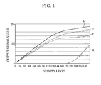
- Fig. 1 shows output values of respective color inks used to record a gray scale image using a conventional ink-jet recording apparatus.
- the horizontal axis represents the density level for each color of the image, the density level varying from 0 to 255.
- the vertical axis represents output signal values (0 to 255) of respective ink colors used to achieve the density.
- three colors C, M, and Y are used to form a gray image. The ratio among the output signal values of the three colors is adjusted to prevent the recorded color deviation.
- a black ink (K) is used for a range in which the input signal value is higher than 176.
- K black ink
- the output signal value for the black ink increases with the input signal value, up to a value of 128, which corresponds to the highest density.
- a pigment ink is used for the black ink.
- the output curves of Fig. 1 are examples and the shapes of the curves are not limited to those shown herein.
- Use of the black ink may be started at a value greater or smaller than 176, and the output value of black at the maximum density (255) may be greater than 128 up to 255.
- the output signal values for the color inks need not be monotonically increased as shown in the example of Fig. 1. Rather, the output signal values for color inks may be decreased after use of the black ink is started.
- Ink jet-recording apparatuses are also used to print photographic images that are comparable to silver halide photographs.
- granularity in such photographic images is perceptible to a user.
- Granularity refers to a visually perceptible rough texture that appears in an image due to ink dots used to record the image on a recording medium. In essence, images with visible granularity are considered low quality compared to silver halide photographs.
- Fig. 2 shows output values of respective ink colors employed by an ink-jet recording apparatus using a plurality of inks that are similar in color but different in density, wherein output values are plotted in a manner similar to Fig. 1.
- C cyan
- M magenta
- Y yellow
- K black
- LC light cyan
- LM light magenta
- the gray scale image is formed using LC, LM and Y. If the high-density inks are used in this range, dots are formed sparsely and a visible granular texture appears. To avoid such granularity, low-density inks are used. When low-density (light color) inks are used, ink dots formed on a recording medium are not easily perceptible.
- Fig. 2 as in Fig. 1, the ratio among the output signal values of the three colors is adjusted to prevent the recorded color deviation.
- the output signal values of LM and LC increase with the input signal value, and reach their maximum values. Densities still higher than these values cannot be obtained by using these inks.
- an image recorded on a recording medium is fully filled with many dots, and thus granularity due to dots is not easily perceptible.
- inks of C, M, and K are gradually added. This allows an increase in density while maintaining low granularity.
- output values of C, M, and K are increased, the output values of LC, LM, and Y are decreased.
- the output value of K exceeds the output value of any other ink and the output value of K is further increased to obtain a high density for black and thus higher quality.
- ink-jet recording apparatuses are designed to achieve high quality for color images.
- monochrome images they are designed to achieve high quality, high contrast, and high density when text is recorded.
- middle density range and the low density range ink-jet recording apparatuses are designed to obtain a gray tone which varies smoothly with the maximum density without having a recorded color deviation. Low granularity is also maintained.
- Fig. 11 shows the ideal position for gray in the a*b* plane of the CIE-L*a*b* space and also shows the position for a recorded gray color corresponding to an input value of 128 shown in Fig. 2.
- the a*b* plane refers to a 2-dimensional coordinate system in which hues are represented. Theoretically, an achromatic color is located at the origin of the a*b* plane.
- the position of gray obtained by conventional image processing for a density level of 128 is denoted by P.
- the image forming method the present invention is capable of outputting a high-quality monochrome photographic image using a good gray scale representation with color deviation or color transition.
- the monochrome photographic images have gray tones in the low density range and the middle density range to achieve high quality.
- the present invention provides an image forming method for forming an image on a recording medium based on image data and using a plurality of color materials, comprising the steps of specifying a monochrome mode to form the image, and when the monochrome mode is specified, performing image processing including the process of converting a multilevel luminance signal corresponding to the image to be formed to multilevel density signals corresponding to the respective color materials used to form the image, wherein in the image processing step, the multilevel luminance signal is converted to the multilevel density signals such that a density signal for a color material of an achromatic color is higher than a density signal for a color material of any chromatic color over an entire range of the multilevel luminance signal.
- the present invention provides an image forming method for forming an image on a recording medium based on image data and using a plurality of color materials, comprising the steps of specifying a first monochrome mode or a second monochrome mode in which to form the image, when the first monochrome mode is specified, performing first image processing including the process of converting a multilevel luminance signal corresponding to the image to be formed to multilevel density signals corresponding to the respective color materials, when the second monochrome mode is specified, performing second image processing including the process of converting the multilevel luminance signal corresponding to the image to be formed to multilevel density signals corresponding to the respective color materials, forming the image on the recording medium in accordance with the multilevel density signal obtained in the first image processing or the second image processing, wherein in the first image processing, the multilevel luminance signal is converted to the multilevel density signals such that a density signal corresponding to an achromatic color material has a value smaller than a value of any density signal corresponding to a chromatic color material in
- the present invention provides an image forming method for forming an image on a recording medium based on image data and using a plurality of color materials, comprising the steps of specifying a monochrome mode to form the image in monochrome, when the monochrome mode is specified, performing image processing including the process of converting the multilevel luminance signal corresponding to the image to be formed to multilevel density signals corresponding to the respective color materials, and forming the image on the recording medium in accordance with the multilevel density signal, wherein the multilevel density signals obtained via the image processing include, over an entire density range, at least one density signal corresponding to a chromatic color material of the plurality of color materials and a density signal corresponding to a color material of an achromatic color and having a value greater than the value of the at least one density signal corresponding to the chromatic color material.
- the present invention provides a program for causing a computer to execute a process of performing signal processing on a signal corresponding to an image to be formed, the process comprising the steps of specifying a monochrome mode to form the image in monochrome, and when the monochrome mode is specified, performing image processing including the process of converting a multilevel luminance signal corresponding to the image to be formed to multilevel density signals respectively corresponding to a plurality of color materials used to form the image, wherein in the image processing step, the multilevel luminance signal is converted to the multilevel density signals such that a density signal for a color material of an achromatic color is higher than a density signal for a color material of any chromatic color over an entire range of the multilevel luminance signal.
- the present invention provides a program for causing a computer to execute a process of performing signal processing on a signal corresponding to an image to be formed, the process comprising the steps of specifying a monochrome mode to form the image in monochrome, and when the monochrome mode is specified, performing image processing including the process of converting a multilevel luminance signal corresponding to the image to be formed to multilevel density signals respectively corresponding to a plurality of color materials used to form the image, wherein the multilevel density signals obtained via the image processing include, over an entire density range, at least one density signal corresponding to a chromatic color material of the plurality of color materials and a density signal corresponding to a color material of an achromatic color and having a value greater than the value of the at least one density signal corresponding to the chromatic color material.
- the present invention provides an image forming system for forming an image on a recording medium based on image data and using a plurality of color materials, comprising means for specifying a monochrome mode to form the image in monochrome, image processing means for, when the monochrome mode is specified, performing image processing including the process of converting a luminance signal corresponding to the image to be formed to multilevel density signals corresponding to the respective color materials, and recording means for forming the image on the recording medium in accordance with the multilevel density signals, wherein the multilevel density signals produced by the image processing means include, over an entire density range, at least one density signal corresponding to a chromatic color material of the plurality of color materials and a density signal corresponding to a color material of an achromatic color and having a value greater than the value of the at least one density signal corresponding to the chromatic color material.
- the present invention in one of the first to sixth aspects described above, it is possible to compensate for a slight recorded color deviation which occurs when an achromatic color material is recorded on a recording medium, by adding a small amount of chromatic color material which cancels out the recorded color deviation, thereby making it possible to represent high-quality gray over the entire density range without producing a recorded color deviation or a color transition.
- Fig. 1 is a graph showing ink output values when a gray scale image is recorded by a conventional ink-jet recording apparatus by using four color inks.
- Fig. 2 is a graph showing ink output values when a gray scale image is recorded by a conventional ink-jet recording apparatus by using six color inks.
- Fig. 3 shows the internal structure of an ink-jet recording apparatus according to an embodiment of the present invention.
- Fig. 4 is a schematic diagram showing a recording head including an array of orifices.
- Fig. 5 is a block diagram showing an image processing system according to an embodiment of the present invention.
- Fig. 6 is a block diagram showing an image data conversion process.
- Fig. 7 is a flow chart of a pre-process performed by a printer in response to a record start command, before a recording process is actually started.
- Fig. 8 is a diagram showing a recording mode setting screen displayed on a CRT.
- Fig. 9 is a graph showing an example of a color conversion process according to an embodiment of the present invention.
- Fig. 10 is a graph showing an example of a color conversion process according to an embodiment of the present invention.
- Fig. 11 shows positions in an a*b* plane for ideal gray and gray output according to a conventional image processing method.
- Fig. 12 shows a desirable gray region in the a*b* plane.
- Fig. 13 shows a graph showing a result of a panel test.
- Fig. 3 shows the internal structure of an ink-jet recording apparatus according to the first embodiment of the present invention.
- Reference numeral 1 denotes a recording medium such as a plastic sheet.
- a plurality of recording media is placed in the form of a stack in a cassette (not shown) or the like.
- recording media is fed one by one by a feed roller (not shown) into a main part of the printer.
- Reference numeral 3 denotes a first transport roller pair
- reference numeral denotes a second transport roller pair.
- the first and second transport roller pairs are disposed at locations spaced apart by a distance as shown in Fig. 3.
- the first transport roller pair 3 and the second transport roller pair 4 are driven by different stepping motors (not shown) such that the recording medium 1 pinched by respective roller pairs is transported in a direction denoted by an arrow A.
- Reference numerals 5a to 5f denote ink tanks for supplying inks to an ink-jet recording head 11, wherein black (K) ink is stored in an ink tank 5a, light cyan (LC) ink in an ink tank 5b, light magenta (LM) ink in an ink tank 5c, cyan (C) ink in an ink tank 5d, magenta (M) ink in an ink tank 5e and yellow (Y) ink in an ink tank 5f.
- the recording head 11 is disposed such that a plane of orifices for firing ink droplets faces the recording medium 1 held in a slightly tensioned fashion between the first transport roller pair 3 and the second transport pair 4.
- the recording head 11 may be constructed such that parts for firing respective six color inks are formed separately or they are integrated in a single piece.
- the recording head 11 and the ink tank 5 are removably mounted on a carriage 6.
- a carriage motor 10 drives the carriage 6 via two pulleys 8a and 8b and a belt 7 such that the carriage 6 moves to and fro in direction denoted by an arrow B along a guide shaft 9.
- Reference 2 denotes a recovery unit for maintaining the recording head 11.
- the recording head 11 returns to its home position at which the recovery unit 2 is disposed.
- the recovery unit 2 recovers the recording head 11 when the recording head 11 returns the home position. More specifically, the recovery unit 2 removes residual ink blocking orifices of the recording head 11.
- ink droplets are fired with proper timing from the recording head 11 in accordance with an image signal while the carriage 6 moves in directions denoted by the arrow B.
- the recording head 11 scans the recording medium 1 once across the full width of the recording medium 1 while firing ink droplets, the recording medium 1 is moved forward by a fixed distance by the transport roller pairs 3 and 4. The scanning by the recording head 11 and moving the recording medium 1 forward are alternately performed thereby forming an image on the recording medium 1.
- Fig. 4 schematically shows an array of ink firing orifices of the recording head 11.
- Line arrays of orifices for firing inks of respective color inks are arranged in the same direction as the direction denoted by the arrow B in which the carriage 6 is scanned, in the same order as that in which color inks stored in the ink tanks 5a to 5f.
- Many orifices for firing each color ink are arranged at intervals of about 40 ⁇ m in the same direction as the direction denoted by the arrow A in which the recording medium 1 transported.
- a line of an image with a resolution of, for example, 600 dpi (dots per inch) is formed on the recording medium 1.
- an ink droplet of about 2 ng is fired from each orifice.
- the amount of each ink droplet is set to be 2 ng such that granularity of dots sparsely formed by black ink on a recording medium is not substantially perceptible when viewed from the distance of distinct view.
- FIG. 5 is a block diagram showing an image processing system according to the present embodiment.
- a host computer 101 includes a CPU 102, a memory 103, an external storage unit 104, an input unit 105, a CRT 108, and an interface 106.
- the CPU 102 performs various processes including image data conversion and recording by executing a program stored in the external storage unit 104.
- the memory 103 is used as a work area in the data conversion process.
- the memory 103 is also used to temporarily store image data.
- the program of processes such as image data conversion may be supplied to the host computer 101 from an external apparatus (not shown).
- a user inputs a command via an input unit 105 while viewing information displayed on the CRT 108.
- the host computer 101 is connected to the ink-jet recording apparatus 107 via the interface 106. After image data is subjected to data conversion, the resultant image data is transmitted, under the control of the CPU 102, to the ink-jet recording apparatus 107.
- the ink-jet recording apparatus 107 performs recording in accordance with the received image data.
- Fig. 6 is a block diagram of an image data conversion process performed by the CPU 102 according to the present embodiment.
- 8-bit (256-level) image data including red (R), green (G) and blue (B) luminance signals is converted to 1-bit data of cyan (C), magenta (M), yellow (Y), light cyan (LC), light magenta (LM), and black (K) in a form that can be handled by the ink-jet recording apparatus.
- the 8-bit R, G, and B luminance signals are first input to a color conversion unit 201 and converted to luminance signals of C, M, Y, LC, LM, and K.
- a 3-dimensional color conversion lookup table LUT
- the CPU 102 refers to the lookup table and determines density signal values of C, M, Y, K, LC, and LM corresponding to a given combination of R, G, and B signal values.
- the lookup table does not have density signal values for all signal levels of R, G, and B signals but has only density signal values for particular discrete sets of R, G, and B signal levels.
- the lookup table cannot be applied directly to all possible combinations of R, G, and B signal levels each taking one of 256 levels.
- density signal values are determined by means of interpolation using a plurality of data corresponding to a plurality of combinations of R, G, and B signal levels. Interpolation is well known in the art and a detail description thereof is omitted.
- the density signal values obtained via the color conversion process 201 are expressed in 8 bits as with the input values, that is, the luminance signal values. That is, each density signal has one of 256 signal levels.
- the image data is subjected to a conversion process performed by an output gamma correction unit 202.
- the output gamma correction unit 202 corrects the input luminance signals of respective ink colors such that the optical density finally represented on a recording medium of each color has a linear relationship with the input density signal of a corresponding color.
- the conversion is performed according to a 1-dimensional lookup table prepared for each color.
- the resultant signals output from the output gamma correction unit 202 are expressed in 8 bits as with the input values.
- the 8-bit density data output from the output gamma correction unit 202 is supplied to a quantization unit 203 for quantization.
- the amount of each ink droplet fired from the recording head is fixed to 2 ng. Therefore, the density at each pixel on the recording medium is represented on two levels: one level obtained by recording a 2 ng ink droplet and the other level with no ink droplet recorded. If an area with a particular size including a plurality of pixels is viewed macroscopically, the color density for that area is the number of pixels recorded with ink droplets. This method of representing the density is called an area coverage modulation method.
- quantization is required to convert multilevel data to 2-level data, as with the present embodiment.
- Known quantization techniques such as error diffusion or dithering may be used.
- the above-described processes performed by the color conversion unit 201, the output gamma correction unit 202, and the quantization unit 203 are optimized depending on the type of recording medium used and/or the type of image formed on the recording medium.
- the lookup tables used in the color conversion process performed by the color conversion unit 201 and the output gamma correction performed by the output gamma correction unit 202 are prepared for each recording medium type.
- Fig. 7 is a flow chart of a pre-process performed by the printer in response to a start recording command issued by a user before actual recording is started.
- the CPU 102 displays a record mode selection screen on the CRT 108 (step S1).
- Fig. 8 shows an example of such a screen displayed in step S1 on the CRT 108.
- the ink-jet recording apparatus can handle several types of recording media.
- a recording method most suitable for the type of a recording medium used is selected from a plurality of available methods.
- the switching of the recording method is performed in accordance with a specified recording mode.
- the details of the recording method are set by the user by inputting data specifying recording conditions via a recording mode setting screen.
- An example of the recording mode setting screen is shown in Fig. 8.
- the user specifies the type of an image (document, picture, etc.) to be recorded via an auto palette 81.
- the type of a recording medium on which to record the image is selected via a paper type selection list box 82.
- a gray scale printing check box 83 is used to specify whether the image is to be recorded in the gray scale printing mode.
- step S2 it is determined whether the specified recording mode is a monochrome mode (monochrome photograph mode, in this embodiment).
- the term “monochrome mode” refers to a recording mode that is applied when a monochrome photograph is output. This mode does not refer to all of the recording mode that is applied when gray scale printing is selected (using check box 83). To further emphasize this distinction, the term “monochrome mode” will herein be referred to as the "monochrome photograph mode".
- the monochrome photograph mode is applied when the gray scale printing is selected by checking the check box 83 and further super quality photo paper is selected in the paper type selection list box 82.
- the conversion process #2 in the monochrome photograph mode, density data for use in recording a gray scale image using a combination of inks, as will be described later with reference to Fig. 9, in accordance with a color conversion table dedicated to the monochrome photograph mode.
- this conversion process #2 multilevel density signals of respective ink colors including black are produced such that more black ink is used than the other color inks over the entire density range including the low density range and the high density range.
- the conversion process #2 includes the image data conversion process described earlier with reference to Fig. 6.
- step S2 if the specified recording mode is not the monochrome photograph mode, the process proceeds to step S3.
- step S3 it is determined whether the check box 83 was checked in step S1 to specify gray scale printing. If the check box 83 is on, the process proceeds to step S4.
- step S3 it is determined in step S3 that the check box 83 associated with gray scale printing is off, the process proceeds directly to step S5 from step S3.
- step S5 a conversion process #1 is performed on the image data.
- the conversion process #1 also includes an image conversion process, but the details thereof are different from those of the conversion process #2. More specifically, in the case in which the process has proceeded directly to step S5 (without proceeding via step S4), the conversion process #1 in step S5 is performed such that multilevel density signals corresponding to respective color inks to be used to record a color image are produced based on a color conversion table, which is known in the art. On the other hand, in the case in which the process has proceeded to step S5 via step S4, the conversion process #1 in step S5 is performed such that multilevel density signals of respective ink colors for use in recording a gray scale image are produced as shown in Fig. 2 in accordance with the color conversion table prepared for use in the color mode.
- step S8 After the image data is subjected to the conversion process in step S5 or S7, the resultant image data in the form of 2-level data is transferred to the ink-jet recording apparatus (step S8).
- the monochrome photograph mode is applied only when super quality photo paper is selected as a recording medium. Therefore, in the conversion process #2 in step S7, a conversion method optimized for super quality photo paper is used. On the other hand, in the conversion process #1 (step S5), an optimum conversion method is selected depending on the type of the recording medium. More specifically, in the conversion process #1, depending on the type of recording medium other than super quality photo paper, a suitable lookup table is selected from a plurality of prepared lookup tables, the color conversion and the output gamma correction are performed using the selected lookup table.
- a horizontal axis represents the luminance signal (L) that can take a value in the range from 0 (black) to 255 (white).
- L luminance signal
- a vertical axis represents density signals of respective color inks as a function of the luminance signal. The density signal can take a value in the range from a minimum value 0 (white) to a maximum value 255 (black). The amount of each color ink applied to unit region (one pixel region) increases with the density signal.
- An advantage of the present embodiment is that the color conversion in the monochrome photograph mode is performed as described with reference to Fig. 9.
- the color conversion is performed in a similar manner to the conventional color mode or monochrome mode.
- the conversion process may be performed in a similar manner as described earlier with reference to Fig. 2.
- the density value of black is always greater than other ink colors and changes monotonically in a highlight range in which the density is low and a high-density range.
- the black luminance curve is plotted for a gamma value of 1.8, although the gamma value is not limited to 1.8.
- cyan and yellow are used.
- the output signals of both cyan and yellow are at low levels over the entire range.
- these two chromatic colors, cyan and yellow are used to compensate for recorded color deviation, and no other colors are used.
- one color ink (yellow ink) is used over the entire density range from the minimum density to the maximum density together with the black ink
- the other chromatic color ink (cyan ink) is used only in a density range higher than a middle level.
- gray which is an achromatic color, using basic colors consisting of cyan, magenta, and yellow.
- black ink is used to represent an achromatic color
- a slight recorded color deviation can occur depending on the type of recording medium.
- cyan ink and yellow ink are used to compensate for the slight recorded color deviation that occurs when black ink is used to record on super quality photo paper.
- An advantage of the present invention is the use of one or more chromatic color inks to compensate for recorded color deviation that occurs when an image is formed using black ink.
- the chromatic color is recorded even in the low-density range when black is recorded.
- the chromatic colors used herein are not used to reduce granularity and are not used as basic colors to form gray.
- the output curves increase monotonically in any density range without crossing one another.
- the size and the perceptibility of granularity of dots formed on a recording medium depend on color and other characteristics of the recording medium. Therefore, for a given amount of ink droplet, it is difficult to determine whether granularity is a problem, unless the type of the recording medium used is taken into consideration. However, in general, for widely used ink-jet recording devices and for widely used recording media, it is desirable that the amount of ink droplet per dot be equal to or less than 5 ng, and more desirably equal to or less than 2 ng.
- the color conversion process (conversion process #2) applied.
- the present embodiment is not limited to such an example.
- the conversion process #2 may be performed regardless of whether an image to be recorded is a photographic image. That is, the present embodiment may be applied regardless of whether an image to be recorded is a photograph, and the conversion process #2 may be performed whenever the monochrome mode is selected to record an image in gray scale. This makes it possible to prevent recorded color deviation and color transition from occurring, not only for monochrome photographic images but also for any image in gray scale.
- cyan and yellow are used as chromatic colors to compensate for the recorded color deviation in the monochrome mode as described above with reference to Fig. 9.
- the present embodiment is not limited to cyan and yellow as chromatic colors.
- Other chromatic colors may be used to compensate of the recorded color deviation, and the curves of chromatic colors may be properly defined depending on the type a recording medium and/or other factors. For example, when an image is recorded on a particular type of recording medium using only black ink, if the color tone of the resultant image is at a point deviated toward cyan from an ideal gray point in the color space, then yellow and magenta may be used as chromatic colors to compensate, as shown in Fig. 10.
- a combination of cyan and magenta may be used depending on the situation.
- a combination of low-density inks such as light cyan and light magenta may be used.
- Colors other than the six colors described above may be used. For example, red (R), green (G), and/or blue (B) may be used to compensate for black.
- the number of inks used for compensation is not limited to two. One color or more colors may be used.
- At least one chromatic color is used to cancel out a particular color saturation that occurs when an image is recorded on a particular type of recording medium using a black ink, and the density of the chromatic color ink used is set to be lower than the density of black ink over the entire density range in gray scale.
- image processing is performed such that a black ink and at least one chromatic ink (for example, yellow ink) are used over the entire density range including the low density range and the high density range, and such that the amount of the black ink is dominant compared with the other color inks, thereby preventing the recorded color deviation and color transition from occurring.
- a black ink and at least one chromatic ink for example, yellow ink
- the color conversion process (conversion process #2) according to the present invention is performed in a plurality of monochrome modes in which different types of chromatic color inks are used together with an achromatic color ink.
- the plurality of monochrome modes include a first monochrome mode in which a gray scale image is recorded using a black ink, a yellow ink, and a cyan ink as shown in Fig. 9, and a second monochrome mode in which a gray scale image is recorded using a black ink, a yellow ink, and a magenta ink as shown in Fig. 10.
- the desirable gray tone depends on specific users.
- the provision of the plurality of monochrome modes makes it possible to handle a difference in user preference in terms of desirable gray tone.
- a first gray scale image is recorded on a recording medium in the first monochrome mode and a second gray scale image is recorded on the same type recording medium (for example, plain paper) in the second monochrome mode
- some users evaluate the first gray scale image as being better than the second gray scale image, but other users evaluate otherwise.
- a greater amount of cyan ink is used than in the second monochrome mode, and thus the first gray scale image gives users a cold impression compared with the second gray scale image. Users who like such a tone select the first gray scale mode.
- the second monochrome mode a greater amount of magenta ink is used than in the first monochrome mode, and thus the second gray scale image gives users a warm impression compared with the first gray scale image. Users who like such a tone select the second gray scale mode.
- a processing flow according to the present embodiment is described briefly.
- the processing flow according to the present embodiment is similar to that according to the first embodiment described earlier with reference to Fig. 7, except for some steps (steps S1, S2, and S7). Thus, the following description will be focused on those different steps.
- a user makes setting associated with the monochrome mode via the driver screen displayed on the CRT 108 of the host computer.
- the driver screen includes two types of check boxes for selecting gray scale printing: first gray scale printing; and second gray scale printing.
- the user can select any one of these two types of check boxes. For example, if the user likes a cold gray tone image than a warm gray tone image, the user may select the first monochrome mode in which a resultant image tends to have a cold tone. Conversely, if the user likes the warm gray tone than the cold gray tone, the user may select the second monochrome mode in which a resultant image tends to have a warm tone.
- the selected recording mode is the monochrome mode such as the first or second monochrome mode.
- the monochrome mode is applied when the check box 83 is checked to select the first gray scale printing mode or the second gray scale printing mode.
- step S7 the process proceeds to step S7 via step S6 to perform the conversion process #2 according to the present invention.
- the conversion process #2 in step S7 for monochrome photograph images includes a conversion process #2A and a conversion process #2B. If the first monochrome mode was selected in step S2, the conversion process #2A is performed. On the other hand, if the second monochrome mode was selected in step S2, the conversion process #2B is performed.
- image processing is performed according to a first monochrome-mode color conversion table to produce density data for use in recording a gray scale image using a combination of inks as shown in Fig. 9. More specifically, multilevel density signals of respective ink colors consisting of black, yellow, and cyan are produced such that more black ink is used than the other color inks over the entire density range including the low density range and the high density range.
- image processing is performed according to a second monochrome-mode color conversion table to produce density data for use in recording a gray scale image using a combination of inks as shown in Fig. 10. More specifically, multilevel density signals of respective ink colors consisting of black, yellow, and magenta are produced such that more black ink is used than the other color inks over the entire density range including the low density range and the high density range.
- the combinations of chromatic inks are not limited to those.
- one type of chromatic color ink may be used or other combinations of two types of chromatic color inks may be used.
- a third monochrome mode may be added in which a black (achromatic color) ink, a cyan ink, and a magenta ink are used.
- an additional monochrome mode may be added in which a color conversion table is used which is similar to the color conversion table for use in the conversion process #1 shown in Fig. 1 in the color mode, and a similar combination of inks to that shown in Fig. 2 is used.
- the color conversion process (conversion process #2) according to the present invention includes a plurality of monochrome modes that are different in terms of the types of chromatic color inks used together with the black ink, thus, gray scale images with different tones can be produced. This provides, in addition to advantages similar to the advantages achieved by the first embodiment, the ability to handle a wide variety of user preferences.
- the color conversion process (conversion process #2) according to the present invention is performed in a plurality of monochrome modes that are different in terms of the types of chromatic color inks used together with black ink and one of these monochrome modes is selected depending on the type of a recording medium used.
- the plurality of monochrome modes include a first monochrome mode in which a gray scale image is recorded using a black ink, a yellow ink, and a cyan ink as shown in Fig. 9, and a second monochrome mode in which a gray scale image is recorded using a black ink, a yellow ink, and a magenta ink as shown in Fig. 10, wherein the first monochrome mode is selected when a first type of recording medium (for example, super quality photo paper) is used, while the second monochrome mode is selected when a second type of recording medium (for example, photo paper or mat paper) is used.
- a first type of recording medium for example, super quality photo paper
- a second type of recording medium
- the advantages obtained by providing the plurality of monochrome modes depending on the type of recording medium are as follows.
- the white color of many recording media varies depending on the type of recording media. If a gray scale image is recorded on different types of recording media using the same combination of inks, the resultant gray scale images are different in tone.
- the present embodiment provides monochrome modes (a first monochrome mode and a second monochrome mode) depending on the type of recording media (super quality photo paper and professional photo paper).
- a processing flow according to the present embodiment is described briefly.
- the processing flow according to the present embodiment is similar to that according to the first embodiment described earlier with reference to Fig. 7, except for some steps (steps S2 and S7). Thus, the following description will be focused on those different steps.
- step S2 it is determined whether the selected recording mode is the monochrome mode.
- the monochrome mode is applied when the gray scale printing is selected by checking the check box 83 and super quality photo paper or professional photo paper is selected in the paper type selection list box 82. More specifically, the first monochrome mode is applied when the gray scale printing is selected by checking the check box 83 and super quality photo paper is selected in the paper type selection list box 82, while the second monochrome mode is applied when the gray scale printing is selected by checking the check box 83 and professional photo paper is selected in the paper type selection list box 82.
- step S7 the process proceeds to step S7 via step S6 to perform the conversion process #2 according to the present invention.
- the conversion process #2 in step S7 for monochrome photograph images includes a conversion process #2A and a conversion process #2B. If the first monochrome mode was selected in step S2, the conversion process #2A is performed. On the other hand, if the second monochrome mode was selected in step S2, the conversion process #2B is performed.
- image processing is performed according to a first monochrome-mode color conversion table to produce density data for use in recording a gray scale image using a combination of inks as shown in Fig. 9. More specifically, multilevel density signals of respective ink colors consisting of black, yellow, and cyan are produced such that more black ink is used than the other color inks over the entire density range including the low density range and the high density range. Based on the multilevel density signals produced in the above-described manner, a gray scale image is recorded on super quality photo paper.
- image processing is performed according to a second monochrome-mode color conversion table to produce density data for use in recording a gray scale image using a combination of inks as shown in Fig.
- multilevel density signals of respective ink colors consisting of black, yellow, and magenta are produced such that more black ink is used than the other color inks over the entire density range including the low density range and the high density range.
- a gray scale image is recorded on professional photo paper.
- a similar tone is obtained in both the gray scale image recorded on the super quality photo paper and the gray scale image recorded on professional photo paper. That is, it is possible to satisfy the need for obtaining a gray scale image with a similar tone when the image is recorded on a recording medium designed to record a photographic image, regardless of the type of the recording medium as long as it is designed to record a photographic image.
- the present embodiment provides two types of monochrome modes depending on whether the recording medium used is super quality photo paper or professional photo paper.
- the present embodiment may provide a third monochrome mode for use in recording a gray scale image on another type of recording medium other than super quality photo paper and professional photo paper.
- Chromatic color inks to be used together with an achromatic color ink may be selected such that a recorded gray scale image has a similar tone to that recorded on super quality photo paper or professional photo paper.
- the color conversion process (conversion process #2) according to the present invention is performed in a plurality of monochrome modes that are different in terms of the types of chromatic color inks used together with a black ink, and one of the plurality of monochrome modes is selected depending on the type of recording medium used. This makes it possible to obtain a gray scale image with a similar tone, at least for any of particular types recording media.
- achromatic color ink for example, a black ink
- chromatic inks for example, a yellow ink
- the chromatic color inks may be used in a particular part of the density range.
- the color conversion process (conversion process #2) in the monochrome mode is performed such that chromatic color inks are used in a particular part of the luminance signal range (in a particular part of the density range).
- the achromatic color ink is dominantly used compared with the chromatic color inks in any part of the luminance signal range.
- the present embodiment is useful, in particular, in the following cases.
- Such a slight chromatic color component is not visibly perceptible when dots are sparsely recorded. However, dots are recorded densely, the chromatic color component becomes visibly perceptible.
- image processing is performed such that the chromatic color inks are used in the middle density range and the high density range, and such that a greater amount of achromatic color ink is used than the chromatic color inks in the middle density range and the high density range.
- the present embodiment makes it possible to reduce the amount of chromatic color inks used, while suppressing the recorded color deviation in gray scale images.
- the fifth embodiment is similar to the first to fourth embodiments in terms of the structure of the apparatus and the manner of processing described earlier with reference to Figs. 3 to 8.
- professional photo paper is selected in Fig. 8.
- the lookup table used in the conversion process #2 shown in Fig. 7 may include an achromatic color ink and chromatic color inks as in Fig. 9 or 10 and may include only an achromatic color ink.
- a feature of the present embodiment is that the color conversion using a lookup table is performed such that the hue varies in the a*b* plane along a path denoted by an arrow in Fig. 11 so that the gray tone in the low density range and the middle density range which are important in monochrome photographic images can be improved.
- the monochrome mode according to the present embodiment is described below.
- nothing is recorded on a recording medium that is, white color of paper is maintained.
- W represents the coordinates of the original color (white) of the recording medium (professional photo paper) used in the present embodiment. If the recording medium has an ideal white color, its coordinates in a*b* plane are (0, 0). However, in practice, the position in the a*b* plane has a slight deviation from the origin as shown in Fig. 11.
- the luminance signal most frequently has a value in a range from the white level (255) to the middle level (about 128).
- the surface of the recording medium is more filled with dots as the gray scale level increases (as the luminance signal level decreases).
- an originally white area of the recording medium is fully filled with dots when the output density signal reaches the middle level corresponding to a luminance level of 128. This means that the original color tone of the recording medium does not affect the image color tone in the low luminance range (in the high density range) in which the luminance signal level is lower than 128.
- the lookup table is produced such that the coordinates move along the path denoted by an arrow in Fig. 11 in the color conversion process in the conversion process #2 shown in Fig. 7.
- the color conversion process of the conversion process #1 is performed using a lookup table produced in accordance with the conventional image processing method.
- the coordinates of recorded color in the a*b* plane move from W to P along a curved path deviated from a linear path.
- the conversion process #1 is applied in the normal color mode or the gray scale mode that is a mode for monochrome images other than photographic images. In this case, suppression of granularity of images or achievement of as high density of black as possible is more important than the gray halftone, and the deviation from the ideal path in the a*b* plane does not results in a significant problem.
- the sixth embodiment is similar in many respects to the fifth embodiment, and the following discussion will be focused on the difference.
- the lookup table used in the color conversion is produced such that the recorded color as close to the neutral gray M in the a*b* plane is obtained.
- the hue of gray to be achieved is allowed to be set within a wider region in the a*b* plane.
- Fig. 12 shows a desirable gray area in the a*b* plane of the CIE-L*a*b* space allowable in the present embodiment.
- the cold-tone gray and the warm-tone gray are not necessarily limited to the above-descried points in the a*b* plane, but they may be set to other points depending on the preference of users. Depending on users, not only in monochrome photographic images recorded using an ink-jet recording apparatus but also in silver-halide monochrome photographs, cold-tone gray or warm-tone gray may be preferable than neutral gray.
- Fig. 13 shows a result of a panel test for four gray colors, neutral gray M, cold-tone gray R, warm-tone gray O, and yellowish gray Y as a comparative sample.
- the panelists are selected from people with a wide variety of backgrounds such as professionals, semiprofessionals and amateurs without being biased to people with a particular background, and the panel test is performed fairly.
- a wide variety of images including portraits, landscapes, images with many high-density parts, and images with many low-density parts are used as samples subjected to the panel test.
- the cold-tone gray gained the highest arrival ratings.
- the neutral gray gained the next highest approval rating, and the next thereto is warm-tone gray.
- the yellowish gray tested as the comparative sample gained very low approval rating compared with the other gray colors although its location in the a*b* plane is near the neural gray.
- gray preferred by many people is not necessarily neutral gray but that located in a particular area in the lower right quadrant of the a*b* plane. That is, gray preferred by many people is located within a triangle whose vertices are located at M, R, and O that gained high scores in the panel test. Also, a higher score than that of the cold-tone gray is obtained when the lookup table is produced such that gray with a luminance level of 128 is located at the barycenter G of the triangle whose vertices are located at M, R, and O.
- the lookup table used in the color conversion process in the conversion process #2 is then produced based on the above-described panel test. More specifically, the lookup table is produced such that when a monochrome image is recorded on a particular specified type recording medium in accordance with the lookup table representing the conversion correspondence between the multilevel luminance signal and the density signals of respective colors of inks used, the color corresponding to the multilevel luminance signal with the center value is located in the inside of, or on one of sides of, the triangle whose vertices are located at point R(0, -3), point M(1, 0), and point O(3, 0) in the a*b* plane.
- the lookup table is produced such that when a monochrome image is recorded on a particular specified type recording medium in accordance with the lookup table representing the conversion correspondence between the multilevel luminance signal and the density signals of respective colors of inks used, the color corresponding to the multilevel luminance signal with the center value is located in the inside of, or on one of sides of, the triangle whose
- two or more types of lookup tables may be used.
- the provision of two or more types of lookup tables for use in the conversion process #2 makes it possible to output a color selected from various gray tones such as cold-tone gray, warm-tone gray, and neutral gray.
- Fig. 9 shows an example of the correspondence between the luminance signal level and the density signal value for each ink color, which is applied when cold-tone gray according to the present embodiment is selected by a user.
- yellow and cyan are added at fixed ratios to black over the entire gray level range (over the entire density range or over the entire luminance density range) such that cold-tone gray that is slightly deviated toward blue from the neutral gray is obtained.
- Fig. 10 shows an example of the correspondence between the luminance signal level and the density signal value for each ink color, which is applied when warm-tone gray according to the present embodiment is selected by a user.
- yellow and magenta are added at fixed ratios to black over the entire gray level range (over the entire density range) such that warm-tone gray that is slightly deviated toward red from the neutral gray is obtained.
- the color conversion process #2 according to the present invention is applied when professional photo paper is selected and a monochrome photographic image is recorded in the gray scale printing mode.
- the type of the recording medium is not limited to the professional photo paper.
- the conversion process 2 may be used for all these types of recording media.
- a*b* coordinates of white color of bare paper vary depending on the type of recording media, although colors corresponding to the luminance level of 128 can be located at the same coordinates in the a*b* plane. Therefore, it is desirable that the lookup table be prepared for each type of recording media.
- the conversion process #2 may be used also for a monochrome image other than monochrome photographic images when the gray scale printing mode is selected.
- the target hue located at M or the target triangular region in the a*b* plane is obtained when the luminance signal is equal to 128, that is, the center value of the full range of the luminance signal.
- the luminance signal is not limited to 128 at which corresponding location in the a*b* plane falls within such a region.
- the dot density varies from a state in which no dots are formed on a recording medium to a state in which the surface of the recording medium is entirely filled with dots.
- the dot coverage is substantially equal to 100%, that is, almost the entire surface of white recording medium is filled with dots.
- the luminance value at which the corresponding hue should fall within the target region is not necessarily close to 128 (middle value), but the luminance value varies depending on the amount of each ink droplet fired by the ink-jet recording apparatus used or depending on the recorded dot density.
- a substantial portion of the surface of white paper is filled with dots when the luminance level is equal to 128 (middle level), and thus the conversion correspondence is set such that the hue falls within the target region when the luminance level is 128.
- the seventh embodiment can provide advantages similar to those achieved by one of the first to fourth embodiments and also advantages similar to those achieved by one of the fifth and sixth embodiments.
- the ink-jet recording system shown in Fig. 5 is used.
- the type of the ink-jet recording system is not limited to that.
- one or more parts thereof may be disposed in either the host computer or the ink-jet recording apparatus, or all parts may be disposed in a single apparatus.
- the recording mode setting screen includes the check box 83 for specifying the gray scale printing.
- the check box 83 is not necessarily needed.
- the setting screen may be configured such that a user may set the hue and the color saturation of an image to be recorded, and the gray scale mode may be applied when the specified hue and the color saturation fall within particular range.
- the invention is applied to an ink-jet recording apparatus capable of recording an image using six color inks.
- the present invention is not limited to such an ink-jet recording apparatus, but the invention may be applied to a wide variety of recording apparatuses capable of recording a color image using a plurality of color materials.
- the recorded color deviation, color transition, and regularity are problems specific to ink-jet recording apparatuses, and thus the present invention is useful in particular when it is applied to ink-jet recording apparatuses.
- a wide variety of methods are known to fire ink droplets from an ink-jet recording head. Of those many methods, in particular, a method of firing small ink droplets to record a high-resolution image can receive great advantages of the invention.
- it is desirable that the recording head have a large number of densely disposed recording elements each including an electro-thermal transducer element.
Landscapes
- Engineering & Computer Science (AREA)
- Multimedia (AREA)
- Signal Processing (AREA)
- Color Image Communication Systems (AREA)
- Color, Gradation (AREA)
- Facsimile Image Signal Circuits (AREA)
- Ink Jet (AREA)
- Image Processing (AREA)
Applications Claiming Priority (4)
| Application Number | Priority Date | Filing Date | Title |
|---|---|---|---|
| JP2004024843A JP2005217985A (ja) | 2004-01-30 | 2004-01-30 | 画像形成方法及び画像形成システム |
| JP2004024843 | 2004-01-30 | ||
| JP2004024841 | 2004-01-30 | ||
| JP2004024841 | 2004-01-30 |
Publications (3)
| Publication Number | Publication Date |
|---|---|
| EP1560419A2 true EP1560419A2 (de) | 2005-08-03 |
| EP1560419A3 EP1560419A3 (de) | 2008-05-28 |
| EP1560419B1 EP1560419B1 (de) | 2016-08-31 |
Family
ID=34656298
Family Applications (1)
| Application Number | Title | Priority Date | Filing Date |
|---|---|---|---|
| EP05250395.0A Expired - Lifetime EP1560419B1 (de) | 2004-01-30 | 2005-01-26 | Bilderzeugungsverfahren, -system und -programm |
Country Status (3)
| Country | Link |
|---|---|
| US (1) | US7936481B2 (de) |
| EP (1) | EP1560419B1 (de) |
| CN (1) | CN100376405C (de) |
Cited By (1)
| Publication number | Priority date | Publication date | Assignee | Title |
|---|---|---|---|---|
| EP1895760A3 (de) * | 2006-08-31 | 2010-09-29 | Canon Kabushiki Kaisha | Vorrichtung und Verfahren zur Bilderzeugung |
Families Citing this family (15)
| Publication number | Priority date | Publication date | Assignee | Title |
|---|---|---|---|---|
| JP2007166543A (ja) * | 2005-12-16 | 2007-06-28 | Canon Inc | 画像処理装置及びその方法 |
| US7862149B2 (en) | 2006-05-26 | 2011-01-04 | Canon Kabushiki Kaisha | Ink jet printing apparatus and printing method |
| JP4235657B2 (ja) * | 2006-05-26 | 2009-03-11 | キヤノン株式会社 | インクジェット記録装置および記録方法 |
| JP4935204B2 (ja) * | 2006-06-26 | 2012-05-23 | セイコーエプソン株式会社 | 画像作成装置、画像作成方法および画像作成プログラム |
| JP4684959B2 (ja) * | 2006-07-04 | 2011-05-18 | キヤノン株式会社 | 画像処理装置、画像処理方法およびプログラム |
| JP4350734B2 (ja) * | 2006-08-30 | 2009-10-21 | キヤノン株式会社 | 画像形成装置及び画像形成方法、並びに、コンピュータプログラムおよび記憶媒体 |
| JP4823052B2 (ja) * | 2006-12-22 | 2011-11-24 | キヤノン株式会社 | 画像出力方法および画像出力装置 |
| KR20100046532A (ko) * | 2008-10-27 | 2010-05-07 | 삼성전자주식회사 | 화상형성장치, 화상형성시스템 및 그 인쇄방법 |
| JP5272982B2 (ja) | 2009-09-07 | 2013-08-28 | ブラザー工業株式会社 | プロファイル補正方法及び画像形成装置 |
| JP5538858B2 (ja) * | 2009-12-15 | 2014-07-02 | キヤノン株式会社 | 画像処理装置および画像処理方法 |
| US20110235060A1 (en) * | 2010-03-29 | 2011-09-29 | Hwai-Tzuu Tai | Screened hardcopy reproduction apparatus compensation data calculation |
| CN103097142A (zh) * | 2010-09-24 | 2013-05-08 | 卡尔斯特里姆保健公司 | 使用测试印迹和密度计的喷墨打印校准技术 |
| US8760496B2 (en) * | 2010-10-26 | 2014-06-24 | Verizon Patent And Licensing Inc. | Methods and systems for presenting adjunct content during a presentation of a media content instance |
| JP5955822B2 (ja) * | 2013-10-25 | 2016-07-20 | 京セラドキュメントソリューションズ株式会社 | 色変換装置、画像形成装置、色変換方法、及び色変換プログラム |
| US20180324328A1 (en) * | 2016-03-18 | 2018-11-08 | Hp Indigo B.V. | Color mapping with phosphorescent materials |
Citations (2)
| Publication number | Priority date | Publication date | Assignee | Title |
|---|---|---|---|---|
| US20020163655A1 (en) | 2001-03-07 | 2002-11-07 | Shixin Zhou | Monochromatic printer and image processing apparatus |
| EP1289269A2 (de) | 2001-08-03 | 2003-03-05 | Seiko Epson Corporation | Drucksystem, Druckverfahren, und Steurungsprogramm für das Drucksystem |
Family Cites Families (19)
| Publication number | Priority date | Publication date | Assignee | Title |
|---|---|---|---|---|
| JPH0652275A (ja) * | 1992-07-31 | 1994-02-25 | Canon Inc | 画像処理方法及び装置 |
| JPH0746417A (ja) * | 1993-07-29 | 1995-02-14 | Canon Inc | カラー印刷装置 |
| US5557712A (en) * | 1994-02-16 | 1996-09-17 | Apple Computer, Inc. | Color map tables smoothing in a color computer graphics system avoiding objectionable color shifts |
| JP3576623B2 (ja) | 1995-02-13 | 2004-10-13 | キヤノン株式会社 | インクジェットプリント方法およびプリント装置 |
| JP3317162B2 (ja) | 1996-10-09 | 2002-08-26 | 東洋インキ製造株式会社 | インクジェット用記録液 |
| EP0843463A3 (de) * | 1996-11-15 | 2000-02-23 | Fuji Photo Film Co., Ltd. | Verfahren zur Umsetzung von Farbreproduktionsdaten |
| JP3817897B2 (ja) * | 1998-04-24 | 2006-09-06 | コニカミノルタビジネステクノロジーズ株式会社 | 画像処理装置 |
| JP2000198227A (ja) * | 1998-10-27 | 2000-07-18 | Canon Inc | インクジェット記録方法、その装置、該装置の制御方法及びコンピュ―タ可読記憶媒体 |
| JP4371560B2 (ja) | 2000-10-05 | 2009-11-25 | キヤノン株式会社 | 画像形成方法及びその装置 |
| US20020071041A1 (en) * | 2000-12-07 | 2002-06-13 | Pine Joshua I. | Enhanced resolution mode using color image capture device |
| GB2371553A (en) | 2000-12-23 | 2002-07-31 | Ilford Imaging Uk Ltd | Inks for Ink Jet Printers |
| JP3922052B2 (ja) | 2001-03-07 | 2007-05-30 | セイコーエプソン株式会社 | 単色プリンタ、および画像処理装置 |
| CN1237406C (zh) * | 2001-09-27 | 2006-01-18 | 佳能株式会社 | 彩色图像形成装置、彩色图像形成装置的控制方法 |
| JP2003110859A (ja) * | 2001-10-01 | 2003-04-11 | Canon Inc | 画像処理方法、画像処理装置、記憶媒体及びプログラム |
| JP2003143422A (ja) | 2001-10-30 | 2003-05-16 | Seiko Epson Corp | 色変換テーブルデータを記録した媒体、色変換プログラムを記録した媒体、色変換装置、色変換方法、色変換プログラムおよび色変換テーブル |
| JP2003147238A (ja) | 2001-11-12 | 2003-05-21 | Fuji Photo Film Co Ltd | インク用組成物、インクジェット記録方法及びアゾ化合物 |
| JP3855800B2 (ja) * | 2002-02-27 | 2006-12-13 | ブラザー工業株式会社 | 画像処理装置および画像処理方法 |
| JP2004148618A (ja) * | 2002-10-30 | 2004-05-27 | Brother Ind Ltd | カラーインクジェットプリンタ |
| JP5110780B2 (ja) * | 2005-07-28 | 2012-12-26 | キヤノン株式会社 | 画像処理方法及び画像処理装置 |
-
2005
- 2005-01-21 US US11/041,104 patent/US7936481B2/en not_active Expired - Fee Related
- 2005-01-26 EP EP05250395.0A patent/EP1560419B1/de not_active Expired - Lifetime
- 2005-01-31 CN CNB2005100067341A patent/CN100376405C/zh not_active Expired - Fee Related
Patent Citations (2)
| Publication number | Priority date | Publication date | Assignee | Title |
|---|---|---|---|---|
| US20020163655A1 (en) | 2001-03-07 | 2002-11-07 | Shixin Zhou | Monochromatic printer and image processing apparatus |
| EP1289269A2 (de) | 2001-08-03 | 2003-03-05 | Seiko Epson Corporation | Drucksystem, Druckverfahren, und Steurungsprogramm für das Drucksystem |
Cited By (2)
| Publication number | Priority date | Publication date | Assignee | Title |
|---|---|---|---|---|
| EP1895760A3 (de) * | 2006-08-31 | 2010-09-29 | Canon Kabushiki Kaisha | Vorrichtung und Verfahren zur Bilderzeugung |
| US8130416B2 (en) | 2006-08-31 | 2012-03-06 | Canon Kabushiki Kaisha | Image forming apparatus, image forming method, computer program, and recording medium |
Also Published As
| Publication number | Publication date |
|---|---|
| EP1560419A3 (de) | 2008-05-28 |
| US7936481B2 (en) | 2011-05-03 |
| EP1560419B1 (de) | 2016-08-31 |
| CN100376405C (zh) | 2008-03-26 |
| CN1657297A (zh) | 2005-08-24 |
| US20050168495A1 (en) | 2005-08-04 |
Similar Documents
| Publication | Publication Date | Title |
|---|---|---|
| US8310723B2 (en) | Image processing apparatus, printing apparatus, and image processing method | |
| US7936481B2 (en) | Method, system and program for forming an image | |
| US8508794B2 (en) | Image forming using warm and cold black tone inks | |
| US7320510B2 (en) | Image processing method and image processing apparatus | |
| CN101207695A (zh) | 图像输出设备和图像输出方法 | |
| JP2005238835A (ja) | 画像形成方法、プログラム及び画像形成システム | |
| EP1895760B1 (de) | Vorrichtung und Verfahren zur Bilderzeugung | |
| US6302521B1 (en) | Method and apparatus for expanded color space in acoustic ink printing | |
| US8625164B2 (en) | Image forming apparatus and method, computer program, and recording medium using density signal and look-up table | |
| US7403307B2 (en) | Method of selecting inks for use in imaging with an imaging apparatus | |
| JP2005217985A (ja) | 画像形成方法及び画像形成システム | |
| JP2006319961A (ja) | 画像処理装置、記録装置および画像処理方法 | |
| JP2004160859A (ja) | 濃度の異なる複数の無彩色インクを搭載した印刷装置 | |
| JP2001353888A (ja) | 印刷制御装置、画像処理装置 | |
| JP2006263938A (ja) | 印刷装置、画像処理装置、印刷方法、および画像処理方法 | |
| JP2011079322A (ja) | 画像処理方法及び画像処理装置 | |
| JP2003291314A (ja) | モノトーン印刷 |
Legal Events
| Date | Code | Title | Description |
|---|---|---|---|
| PUAI | Public reference made under article 153(3) epc to a published international application that has entered the european phase |
Free format text: ORIGINAL CODE: 0009012 |
|
| AK | Designated contracting states |
Kind code of ref document: A2 Designated state(s): AT BE BG CH CY CZ DE DK EE ES FI FR GB GR HU IE IS IT LI LT LU MC NL PL PT RO SE SI SK TR |
|
| AX | Request for extension of the european patent |
Extension state: AL BA HR LV MK YU |
|
| PUAL | Search report despatched |
Free format text: ORIGINAL CODE: 0009013 |
|
| AK | Designated contracting states |
Kind code of ref document: A3 Designated state(s): AT BE BG CH CY CZ DE DK EE ES FI FR GB GR HU IE IS IT LI LT LU MC NL PL PT RO SE SI SK TR |
|
| AX | Request for extension of the european patent |
Extension state: AL BA HR LV MK YU |
|
| 17P | Request for examination filed |
Effective date: 20081128 |
|
| AKX | Designation fees paid |
Designated state(s): DE FR GB IT |
|
| 17Q | First examination report despatched |
Effective date: 20111219 |
|
| GRAP | Despatch of communication of intention to grant a patent |
Free format text: ORIGINAL CODE: EPIDOSNIGR1 |
|
| INTG | Intention to grant announced |
Effective date: 20160318 |
|
| GRAS | Grant fee paid |
Free format text: ORIGINAL CODE: EPIDOSNIGR3 |
|
| GRAA | (expected) grant |
Free format text: ORIGINAL CODE: 0009210 |
|
| AK | Designated contracting states |
Kind code of ref document: B1 Designated state(s): DE FR GB IT |
|
| REG | Reference to a national code |
Ref country code: GB Ref legal event code: FG4D |
|
| REG | Reference to a national code |
Ref country code: DE Ref legal event code: R096 Ref document number: 602005050106 Country of ref document: DE |
|
| REG | Reference to a national code |
Ref country code: DE Ref legal event code: R097 Ref document number: 602005050106 Country of ref document: DE |
|
| PG25 | Lapsed in a contracting state [announced via postgrant information from national office to epo] |
Ref country code: IT Free format text: LAPSE BECAUSE OF FAILURE TO SUBMIT A TRANSLATION OF THE DESCRIPTION OR TO PAY THE FEE WITHIN THE PRESCRIBED TIME-LIMIT Effective date: 20160831 |
|
| PLBE | No opposition filed within time limit |
Free format text: ORIGINAL CODE: 0009261 |
|
| STAA | Information on the status of an ep patent application or granted ep patent |
Free format text: STATUS: NO OPPOSITION FILED WITHIN TIME LIMIT |
|
| 26N | No opposition filed |
Effective date: 20170601 |
|
| GBPC | Gb: european patent ceased through non-payment of renewal fee |
Effective date: 20170126 |
|
| REG | Reference to a national code |
Ref country code: FR Ref legal event code: ST Effective date: 20170929 |
|
| PG25 | Lapsed in a contracting state [announced via postgrant information from national office to epo] |
Ref country code: FR Free format text: LAPSE BECAUSE OF NON-PAYMENT OF DUE FEES Effective date: 20170131 |
|
| PG25 | Lapsed in a contracting state [announced via postgrant information from national office to epo] |
Ref country code: GB Free format text: LAPSE BECAUSE OF NON-PAYMENT OF DUE FEES Effective date: 20170126 |
|
| PGFP | Annual fee paid to national office [announced via postgrant information from national office to epo] |
Ref country code: DE Payment date: 20201217 Year of fee payment: 17 |
|
| REG | Reference to a national code |
Ref country code: DE Ref legal event code: R119 Ref document number: 602005050106 Country of ref document: DE |
|
| PG25 | Lapsed in a contracting state [announced via postgrant information from national office to epo] |
Ref country code: DE Free format text: LAPSE BECAUSE OF NON-PAYMENT OF DUE FEES Effective date: 20220802 |