EP1559857B1 - Bewegungsumkehrvorrichtung - Google Patents
Bewegungsumkehrvorrichtung Download PDFInfo
- Publication number
- EP1559857B1 EP1559857B1 EP04106342A EP04106342A EP1559857B1 EP 1559857 B1 EP1559857 B1 EP 1559857B1 EP 04106342 A EP04106342 A EP 04106342A EP 04106342 A EP04106342 A EP 04106342A EP 1559857 B1 EP1559857 B1 EP 1559857B1
- Authority
- EP
- European Patent Office
- Prior art keywords
- reversing
- belt
- cover rail
- carrier
- deflection member
- Prior art date
- Legal status (The legal status is an assumption and is not a legal conclusion. Google has not performed a legal analysis and makes no representation as to the accuracy of the status listed.)
- Expired - Lifetime
Links
- 238000006073 displacement reaction Methods 0.000 claims description 8
- 230000008878 coupling Effects 0.000 claims description 4
- 238000010168 coupling process Methods 0.000 claims description 4
- 238000005859 coupling reaction Methods 0.000 claims description 4
- 238000004519 manufacturing process Methods 0.000 description 3
- 239000000314 lubricant Substances 0.000 description 2
- 239000000463 material Substances 0.000 description 2
- 238000000465 moulding Methods 0.000 description 2
- 239000004033 plastic Substances 0.000 description 2
- 229920003023 plastic Polymers 0.000 description 2
- 229910001229 Pot metal Inorganic materials 0.000 description 1
- 229910000639 Spring steel Inorganic materials 0.000 description 1
- 230000004308 accommodation Effects 0.000 description 1
- 230000006978 adaptation Effects 0.000 description 1
- 239000000654 additive Substances 0.000 description 1
- 230000000295 complement effect Effects 0.000 description 1
- 230000000694 effects Effects 0.000 description 1
- 230000002996 emotional effect Effects 0.000 description 1
- 238000009434 installation Methods 0.000 description 1
- 239000002184 metal Substances 0.000 description 1
- 229910052751 metal Inorganic materials 0.000 description 1
Images

Classifications
-
- E—FIXED CONSTRUCTIONS
- E05—LOCKS; KEYS; WINDOW OR DOOR FITTINGS; SAFES
- E05C—BOLTS OR FASTENING DEVICES FOR WINGS, SPECIALLY FOR DOORS OR WINDOWS
- E05C9/00—Arrangements of simultaneously actuated bolts or other securing devices at well-separated positions on the same wing
- E05C9/04—Arrangements of simultaneously actuated bolts or other securing devices at well-separated positions on the same wing with two sliding bars moved in opposite directions when fastening or unfastening
-
- E—FIXED CONSTRUCTIONS
- E05—LOCKS; KEYS; WINDOW OR DOOR FITTINGS; SAFES
- E05B—LOCKS; ACCESSORIES THEREFOR; HANDCUFFS
- E05B53/00—Operation or control of locks by mechanical transmissions, e.g. from a distance
- E05B53/003—Operation or control of locks by mechanical transmissions, e.g. from a distance flexible
-
- E—FIXED CONSTRUCTIONS
- E05—LOCKS; KEYS; WINDOW OR DOOR FITTINGS; SAFES
- E05C—BOLTS OR FASTENING DEVICES FOR WINGS, SPECIALLY FOR DOORS OR WINDOWS
- E05C9/00—Arrangements of simultaneously actuated bolts or other securing devices at well-separated positions on the same wing
- E05C9/20—Coupling means for sliding bars, rods, or cables
Definitions
- the invention relates to a motion reverser according to the preamble of claim 1.
- Such a motion reverser is off DE 203 08 054 U1 known.
- Another motion reverser is out of the EP 0327 264 A1 known.
- one of the drive rods is moved longitudinally over a handle.
- a toothing is provided, which engages in the toothing of a toothed belt.
- the toothed belt is clamped oval over two substantially aligned transversely to the direction of displacement of the drive rods axes, so that two parallel toothed belt sections are opposite.
- the second drive rod is provided with a toothing complementary to the teeth of the toothed belt and is the first drive rod on the parallel toothed belt section opposite.
- the motion reversing device is housed in a housing which in addition to the leadership of the drive rods and the axes also includes an engagement for the driver of a handle over which one of the drive rods can be moved.
- the invention has for its object to provide a space-saving design of the motion reversing device at low production costs.
- a development of the invention provides that the band wraps around a guide body, which is assigned to the faceplate stationary.
- the band on the one hand and the guide body on the other hand can be done in a simple manner, the provision of parallel sections, while the band out and tensioned and done the assignment to the drive rods.
- the guide body has at least one longitudinal groove for receiving a pin or a portion of the pin which is associated with a driver.
- This pin serves for one of the additional guidance of the band, which is thereby held and guided in the cuff rail level.
- the unavoidable and, in the case of the comparatively thin band, protruding fastening lugs can be made e.g. be taken without the need for additional space.
- one of the driver is assigned to the guide body in front of the faceplate.
- the driver can thereby be formed according to the width of the faceplate and the maximum width of the band is essentially limited only to the width of the groove.
- the necessary installation space in front of the face-plate rail can also be kept small.
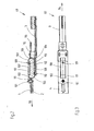
- the motion reversing device 1 serves to control the movement of the drive rods 2 and 3 (FIG. Fig. 2 ) in opposite directions.
- One of the drive rods 2 or 3 is via a drive rod drive, such as in the Fig. 1 visible espagnolette 100, displaced along the face plate 4.
- the drive rods 2, 3 are optionally drivingly connected to further drive rods of an espagnolette, not shown here, and are received on the wing of a window or a door in a Beschlagabilitynut and covered by the face plate 4.
- the drive rods 2, 3 have a U-shaped cross section in the embodiment and are guided longitudinally displaceable below the face plate 4.
- the drive rod 2 is assigned at its end via a pin 101 a driver 111.
- the pin 101 is designed as a stepped pin, so that the driver 111 at a collar of the pin 101 spaced from the face plate 4.
- the driver 111 is guided displaceably on the face-plate rail 4 and has a window 102.
- In this window 102 projects the guide body 103, which has a substantially oval shape.
- the guide body 103 is therefore provided at its end with generous radii 104 and 105.
- a band 106 completely wraps around this guide body 103 and is designed as an endless belt or connected together at its ends.
- the driver 111 is in adapted to its width of the face plate 4, while the window 102 in its transverse to the face plate direction dimensioned only slightly larger than the guide body 103 and the band 106th
- the drive rod 3 is the lower portion 108 via a rivet 110 directly associated. This can preferably be formed out of the drive rod 3, so that a separate Ardsniet and its handling can be omitted.
- the direct assignment of the belt 106 to the drive rod 3 ensures that the components receive the respective maximum cross-sections and thus also load capacity.
- the pin 109 projects beyond the underside of the band 106 with a collar or projection, so that a surface engaging behind the hole in the band 106 is formed on the pin 109.
- the guide body 103 has at least one longitudinal groove 112 for receiving the portion 113 of the pin 109 projecting in the direction of the guide body 103. With a corresponding dimensional adaptation of the section 113 and the longitudinal groove 112 thus results in an additional guidance of the belt 106, which thereby also in the cuff rail plane, ie transversely to the direction of displacement 114 (FIG. Fig. 3 ) of the drive rod 3, held and guided.
- the unavoidable and, in the case of the comparatively thin band 106, protruding fastening lugs, for example of the rivet 110 can be accommodated, without the need for additional space.
- the drive rod 3 is connected via a mounting lug 115 slidably connected to the faceplate 4 and protrudes beyond the end 116 with a coupling portion 117 also.
- the function of the movement reversing device 1 is essentially evident:
- the drive rod 2 is displaced in the direction 118, the band 106 is rotated counterclockwise via the carrier 111 and the pin 109 (FIG. Fig. 2 ) emotional.
- the drive rod 3 is moved in the direction of displacement 114 via the rivet 110 guided along the section 108.
- the Belt 106 is moved clockwise and the drive rods 2,3 are moved opposite each.
- the guide body 103 of the faceplate 4 is assigned stationary.
- the guide body 103 contrary to the representation of the Fig. 2 consists of two halves, which are provided on the sides facing each other with flat surfaces and rivet projections mounted thereon. These are assigned to the top or the bottom of the faceplate 4 and pass through the faceplate 4 and the respective other half of the guide body 103 at provided openings. A projection of the rivet projections can then be riveted in the region of the longitudinal grooves 112.
- the guide body 103 consists essentially of two mounted on the face plate 4 moldings that have no fixed connection to each other. These moldings then have only the radii 104 and 105 and the necessary attachment lugs on the faceplate 4 on it.
- the assignment of the guide body 103 to the faceplate 4 is such that the portion 107 is located in front of the faceplate 4.
- the band 106 is therefore guided both below and above the face-plate 4. Characterized in that the tape 106 is also guided below the faceplate 4 and immersed in the Beschlagabilitynut the wing, the width of the belt 106 and the guide body 103 is to be adjusted according to the width of the Beschlagagenut.
- the rivet 110 is designed as an additional fastening body.
- the shape of the drive rod is advantageous as a U-shaped profile, since on the one hand, the required material thickness of the drive rod 3 can be reduced and thereby the entire height is reduced. On the other hand, the rivet attachment of the rivet 110 can thus be received without projection.
- the length of the longitudinal groove 112 is matched to the maximum displacement of the drive rod 2, so that the overall dimension of the guide body in the longitudinal direction substantially corresponds to the displacement distance of the drive rod 3 plus the radii 104 and 105.
- the molded article would be interpreted as a molded part of die-cast zinc, which on the one hand reduces the manufacturing costs and on the other hand allows production with low tolerances.
- the shaped body 103 is made of a plastic which is already provided with friction-reducing additives. Such plastics are already in use as permanently lubricated bearing materials.
- the band 106 is preferably designed as a metal band, for example made of spring steel.
- Deviating from the illustrations according to Fig. 1 to 3 can also be provided that a cap attached to the faceplate 4 covers the motion reverser 1 and thus prevents the ingress of dirt.
- connection of the belt 106 with the drive rod 3 takes place directly, ie the drive rod 3 is connected directly to the belt 106 via the rivet 110.
- connection takes place according to the connection of the drive rod 2 and the belt 106 via a driver whose structure corresponds to that of the driver 111.
- this would presuppose that either the dimension of the fitting receiving groove allows the accommodation of a second driver or the dimensions of the belt 106 and the guide body 103 are reduced accordingly, which would lead to the already above reduction of the cross sections of the belt 106 and the drive rod 3 ,
Landscapes
- Engineering & Computer Science (AREA)
- Mechanical Engineering (AREA)
- Power-Operated Mechanisms For Wings (AREA)
- Window Of Vehicle (AREA)
- Transmission Devices (AREA)
- Glass Compositions (AREA)
- Liquid Crystal Substances (AREA)
- Superconductors And Manufacturing Methods Therefor (AREA)
Description
- Die Erfindung betrifft eine Bewegungsumkehrvorrichtung nach dem Oberbegriff des Anspruchs 1.
- Eine solche Bewegungsumkehrvorrichtung ist aus
DE 203 08 054 U1 bekannt. - Eine weitere Bewegungsumkehrvorrichtung ist aus der
EP 0327 264 A1 bekannt. Hier ist vorgesehen, dass zum entgegengesetzten Antreiben zweier Treibstangen eines Treibstangenbeschlages eine der Treibstangen über eine Handhabe längsverschoben wird. An der Treibstange ist eine Zahnung vorgesehen, welche in die Zahnung eines Zahnriemens eingreift. Der Zahnriemen ist dazu über zwei im wesentlich quer zur Verschieberichtung der Treibstangen ausgerichtete Achsen oval aufgespannt, so dass sich zwei parallel verlaufende Zahnriemenabschnitte gegenüberliegen. Die zweite Treibstange ist mit einer ebenfalls zur Zahnung des Zahnriemens komplementären Zahnung versehen und liegt der ersten Treibstange an dem parallel verlaufenden Zahnriemenabschnitt gegenüber. - Die Bewegungsumkehrvorrichtung ist dabei in einem Gehäuse untergebracht, welches neben der Führung der Treibstangen und den Achsen auch einen Eingriff für den Mitnehmer einer Handhabe enthält, über den eine der Treibstangen bewegt werden kann.
- Nachteilig ist es dabei, dass diese Bewegungsumkehrvorrichtung viel Bauraum beansprucht, der im Falzbereich zwischen Flügel und Rahmen in nur begrenztem Maße zur Verfügung steht. Daher sind viele bekannte Bewegungsumkehrvorrichtungen in einer Beschlagaufnahmenut des Flügels untergebracht, in der die Treibstangen durch eine Stulpschiene abgedeckt aufgenommen sind. Die Treibstangen sind dazu mit Zahnungen versehen, die mit zwischen den Treibstangen angeordneten Zahnrädern zusammenwirken. Eine derartige Ausgestaltung ist beispielsweise aus der
DE-PS 25 57 303 bekannt. - Aus der
DE 203 08 054 U1 ist es ferner bekannt, eine Schubrichtungsumkehr durch ein flexibles Umlenkglied zu bewirken, welches im wesentlichen vor der Stulpschiene angeordnet ist und somit nicht den beengten Platzverhältnissen innerhalb einer Beschlagaufnahmenut oder ähnlichem angepasst werden muss. Die Kette ist dazu in einer kulissenartigen Führung gespannt und bildet zwei parallel verlaufende Abschnitte aus, die jeweils einem Mitnehmer zugeordnet sind, der jeweils mit einer Treibstange antriebsverbunden ist. - Der Erfindung liegt die Aufgabe zugrunde, eine möglichst platzsparende Ausgestaltung der Bewegungsumkehrvorrichtung bei geringen Herstellungskosten anzugeben.
- Die Lösung dieser Aufgabe gelingt durch die im kennzeichnenden Teil des Anspruchs 1 angegebenen Maßnahmen.
Durch die gefundene Lösung wird eine besonders einfach aufgebaute und aus nur wenigen Bauteilen bestehende Umkehrvorrichtung geschaffen. Das Band kann in einem vergleichsweise engem Radius geführt werden, so dass die Umkehrvorrichtung einen nur geringen Platzbedarf hat. - Eine Weiterbildung der Erfindung sieht vor, dass das Band einen Führungskörper umschlingt, der der Stulpschiene ortsfest zugeordnet ist. Somit kann aus dem Band einerseits und dem Führungskörper andererseits in einfacher Weise die Bereitstellung der parallelen Abschnitte erfolgen, dabei das Band geführt und gespannt werden und die Zuordnung zu den Treibstangen erfolgen.
- Es ist ferner vorgesehen, dass der Führungskörper zumindest eine Längsnut zur Aufnahme eines Zapfens bzw. eines Abschnitts des Zapfens aufweist, der einem Mitnehmer zugeordnet ist. Dieser Zapfen dient zum einen der zusätzlichen Führung des Bandes, welches dadurch auch in der Stulpschienenebene gehalten und geführt ist. Zum anderen können die unvermeidlichen und bei dem vergleichsweise dünnen Band vorstehenden Befestigungsansätze z.B. des Zapfens aufgenommen werden, ohne dass hierzu ein weiterer Platzbedarf entsteht.
- Um den Mitnehmer und auch das Band stabiler ausgestalten zu können ist vorgesehen, dass einer der Mitnehmer dem Führungskörper vor der Stulpschiene zugeordnet ist. Der Mitnehmer kann dadurch entsprechend der Breite der Stulpschiene ausgebildet werden und die maximale Breite des Bandes ist im wesentlichen nur auf die Breite der Nut beschränkt.
- Wenn der Mitnehmer ein Fenster aufweist, mit dem der Mitnehmer den Führungskörper in seiner Abmessung quer zur Stulpschiene umgreift, kann dabei auch der notwendige Bauraum vor der Stulpschiene gering gehalten werden.
- Aufgrund der begrenzten Platzverhältnisse in einer die Bewegungsumkehrvorrichtung aufnehmenden Beschlagaufnahmenut ist es vorteilhaft, wenn die Kopplung der zweiten Treibstange mit dem Band unterhalb der Stulpschiene unmittelbar erfolgt.
- Weitere Vorteile ergeben sich aus den Zeichnungen. Es zeigen:
- Fig. 1
- einen Treibstangenantrieb mit einer Bewegungsumkehrvorrichtung,
- Fig. 2
- eine Längsschnitt durch die Bewegungsumkehrvorrichtung und
- Fig. 3
- eine Draufsicht auf die Bewegungsumkehrvorrichtung.
- In der
Fig. 1 ist die Bewegungsumkehrvorrichtung mit dem Bezugszeichen 1 versehen.
Die Bewegungsumkehrvorrichtung 1 dient dazu, die Bewegung der Treibstangen 2 und 3 (Fig. 2 ) in jeweils entgegengerichtete Richtungen umzuwandeln. Eine der Treibstangen 2 oder 3 wird über einen Treibstangenantrieb, z.B. das in derFig. 1 sichtbare Treibstangengetriebe 100, längs der Stulpschiene 4 verlagert. Die Treibstangen 2, 3 sind dabei ggf. antriebsverbunden mit weiteren Treibstangen eines hier nicht dargestellten Treibstangenbeschlages und werden an dem Flügel eines Fensters oder einer Tür in einer Beschlagaufnahmenut aufgenommen und durch die Stulpschiene 4 abgedeckt. Die Treibstangen 2, 3 haben im Ausführungsbeispiel einen U-förmigen Querschnitt und sind unterhalb der Stulpschiene 4 längsverschiebbar geführt. - Wie in der
Fig. 2 erkennbar, ist die Treibstange 2 an ihrem Ende über einen Zapfen 101 einem Mitnehmer 111 zugeordnet. Der Zapfen 101 ist als Stufenzapfen gestaltet, so dass sich der Mitnehmer 111 an einem Bund des Zapfens 101 von der Stulpschiene 4 beabstandet. Der Mitnehmer 111 ist auf der Stulpschiene 4 verschieblich geführt und weist ein Fenster 102 auf. In dieses Fenster 102 ragt der Führungskörper 103, der eine im wesentlichen ovale Form hat. Der Führungskörper 103 ist an seinen Ende daher mit großzügigen Radien 104 und 105 versehen. Ein Band 106 umschlingt diesen Führungskörper 103 vollständig und ist als Endlosband ausgelegt oder an seinen Enden miteinander verbunden. Der Mitnehmer 111 ist in seiner Breite der Stulpschiene 4 angepasst, während das Fenster 102 in seiner quer zur Stulpschiene verlaufenden Richtung nur wenig größer bemessen ist als der Führungskörper 103 bzw. das Band 106. - Bedingt durch die ovale Form des Führungskörpers 103 entstehen an der durch das Band 106 gebildeten Bandschlaufe zwei parallel verlaufende Abschnitte 107 und 108 mit einer quer zur Stulpschiene 4 verlaufenden Achse. Während im Bereich des oberen Abschnitts 107 der Mitnehmer 111 mittels eines Zapfens 109 an dem Band 106 angreift, ist die Treibstange 3 dem unteren Abschnitt 108 über einen Niet 110 unmittelbar zugeordnet. Dieser kann vorzugsweise aus der Treibstange 3 herausgeformt sein, so dass ein separater Verbindungsniet sowie dessen Handhabung entfallen kann. Die unmittelbare Zuordnung des Bandes 106 zu der Treibstange 3 stellt sicher, dass die Bauteile die jeweils maximalen Querschnitte und damit auch Tragfähigkeit erhalten.
- Der Zapfen 109 steht dabei über die Unterseite des Bandes 106 mit einem Bund oder Ansatz vor, so dass eine die Bohrung in dem Band 106 hintergreifende Fläche an dem Zapfen 109 entsteht. Der Führungskörper 103 weist zumindest eine Längsnut 112 zur Aufnahme des in Richtung des Führungskörpers 103 vorstehenden Abschnitts 113 des Zapfens 109 auf. Bei entsprechender maßlicher Anpassung des Abschnitts 113 und der Längsnut 112 ergibt sich somit eine zusätzlichen Führung des Bandes 106, welches dadurch auch in der Stulpschienenebene, also quer zur Verschieberichtung 114 (
Fig. 3 ) der Treibstange 3, gehalten und geführt ist. Zum anderen können die unvermeidlichen und bei dem vergleichsweise dünnen Band 106 vorstehenden Befestigungsansätze z.B. des Niets 110 aufgenommen werden, ohne dass hierzu ein weiterer Platzbedarf entsteht. - Die Treibstange 3 ist über einen Befestigungsansatz 115 verschiebbar an der Stulpschiene 4 angebunden und ragt über deren Ende 116 mit einem Kupplungsabschnitt 117 hinaus.
- Die Funktion der Bewegungsumkehrvorrichtung 1 ist im wesentlichen ersichtlich: Bei einer Verstellung der Treibstange 2 in Richtung 118 wird über den Mitnehmer 111 und den Zapfen 109 das Band 106 im Gegenuhrzeigersinn (
Fig. 2 ) bewegt. Dadurch wird die Treibstange 3 über den entlang des Abschnitts 108 geführten Niet 110 in Verschieberichtung 114 bewegt. Bei einem umgekehrten Schaltvorgang wird das Band 106 im Uhrzeigersinn bewegt und die Treibstangen 2,3 werden jeweils entgegengesetzt verfahren. - Dabei ist der Führungskörper 103 der Stulpschiene 4 ortsfest zugeordnet. Dazu kann vorgesehen sein, dass der Führungskörper 103 entgegen der Darstellung nach der
Fig. 2 aus zwei Hälften besteht, die auf den einander zugewandten Seiten mit Planflächen und darauf angebrachten Nietvorsprüngen versehen sind. Diese werden der Ober- bzw. der Unterseite der Stulpschiene 4 zugeordnet und durchgreifen die Stulpschiene 4 und die jeweils andere Hälfte des Führungskörpers 103 an dafür vorgesehenen Durchbrüchen. Ein Überstand der Nietvorsprünge kann dann im Bereich der Längsnuten 112 vernietet werden. - Obwohl die Ausgestaltung nach der
Fig. 2 ein Ausknicken des Bandes 106 verhindert, kann auch vorgesehen werden, dass der Führungskörper 103 im wesentlichen aus zwei an der Stulpschiene 4 angebrachten Formkörpern besteht, die keine feste Verbindung zueinander haben. Diese Formkörper weisen dann lediglich die Radien 104 und 105 sowie die notwendigen Befestigungsansätze an der Stulpschiene 4 dazu auf. - Die Zuordnung des Führungskörpers 103 zu der Stulpschiene 4 erfolgt dergestalt, dass der Abschnitt 107 vor der Stulpschiene 4 liegt. Das Band 106 wird daher sowohl unterhalb wie auch oberhalb der Stulpschiene 4 geführt. Dadurch, dass das Band 106 auch unterhalb der Stulpschiene 4 geführt wird und in die Beschlagaufnahmenut des Flügels eintaucht, ist die Breite des Bandes 106 und des Führungskörpers 103 entsprechend der Breite der Beschlagaufnahmenut anzupassen.
- In der
Fig. 2 ist der Niet 110 als zusätzlicher Befestigungskörper ausgeführt. Dabei ist die Formgebung der Treibstange als U-förmiges Profil vorteilhaft, da dadurch zum einen die erforderliche Materialstärke der Treibstange 3 reduziert werden kann und dadurch die gesamte Bauhöhe reduziert wird. Zum anderen kann der Nietansatz des Niets 110 so ohne Überstand aufgenommen werden. - Die Länge der Längsnut 112 ist auf den maximalen Verschiebeweg der Treibstange 2 abgestimmt, so dass die Gesamtabmessung des Führungskörpers in Längsrichtung im wesentlichen der Verschiebestrecke der Treibstange 3 zuzüglich der Radien 104 und 105 entspricht.
- Um die Reibung des Bandes 106 an dem Formkörper zu reduzieren kann bei allen genannten Ausführungsbeispielen vorgesehen werden, dass an den Radien 104, 105 Ausnehmungen zur Aufnahme von Schmierstoffen vorgesehen werden. Diese sichern das Vorhandensein einer gewissen Schmierstoffmenge und verringern dadurch die Reibung und den Verschleiß.
- In diesem Falle wäre der Formkörper als Formteil aus Zinkdruckguss auszulegen, was zum einen die Herstellkosten reduziert und zum anderen eine Herstellung mit geringen Toleranzen zulässt. Es kann aber auch vorgesehen werden, dass der Formkörper 103 aus einem Kunststoff hergestellt wird, der bereits mit reibungsmindernden Zusätzen versehen ist. Derartige Kunststoffe sind bereits als dauergeschmierte Lagerwerkstoffe im Einsatz. Das Band 106 wird vorzugsweise als Metallband beispielsweise aus Federstahl ausgeführt.
- Abweichend von den Darstellungen nach
Fig. 1 bis 3 kann auch vorgesehen werden, dass eine an der Stulpschiene 4 befestigte Abdeckkappe die Bewegungsumkehrvorrichtung 1 abdeckt und somit das eindringen von Schmutz verhindert. - In dem in den
Fig. 1 bis 3 dargestellten Ausführungsbeispielen erfolgt die Verbindung des Bandes 106 mit der Treibstange 3 unmittelbar, d.h. die Treibstange 3 ist direkt über den Niet 110 mit dem Band 106 verbunden. Es kann jedoch auch vorgesehen werden, dass die Anbindung entsprechend der Verbindung der Treibstange 2 und dem Band 106 über einen Mitnehmer erfolgt, dessen Aufbau dem des Mitnehmers 111 entspricht. Dies würde jedoch voraussetzen, dass entweder die Abmessung der Beschlagaufnahmenut die Unterbringung eines zweiten Mitnehmers gestattet oder aber die Abmessungen des Bandes 106 und des Führungskörpers 103 werden entsprechend reduziert, was zu der bereits vorstehenden Reduzierung der Querschnitte von dem Band 106 und der Treibstange 3 führen würde. -
- 1
- Bewegungsumkehrvorrichtung
- 2
- Treibstange
- 3
- Treibstange
- 4
- Stulpschiene
- 100
- Treibstangenantrieb
- 101
- Niet
- 102
- Fenster
- 103
- Führungskörper
- 104
- Radius
- 105
- Radius
- 106
- Band
- 107
- Abschnitt
- 108
- Abschnitt
- 109
- Zapfen
- 110
- Niet
- 111
- Mitnehmer
- 112
- Längsnut
- 113
- Abschnitt
- 114
- Verschieberichtung
- 115
- Befestigungsansatz
- 116
- Ende
- 117
- Kupplungsansatz
- 118
- Richtung
Claims (6)
- Bewegungsumkehrvorrichtung (1) zur entgegengesetzten Verlagerung zweier Treibstangen (2,3) eines Treibstangenbeschlages, bestehend aus einem flexiblen Umlenkglied (106), welches an dem Flügel eines Fensters oder einer Türspannbar bzw. so führbar ist, dass sich zwei parallel zueinander verlaufende Abschnitte (107, 108) des Umlenkgliedes (106) gegenüberliegen, wobei das flexible Umlenkglied im montierten Zustand mit zumindest einem Abschnitt (107) vor einer Stulpschiene (4) liegt, und wobei an zumindest einem Abschnitt (107, 108) ein mit dem Umlenkglied (106) gekoppelter Mitnehmer (111) vorgesehen ist, welcher mit einer der Treibstangen (2 oder 3) koppelbar ist,
dadurch gekennzeichnet,
dass das Umlenkglied aus einem Band (106) besteht, das in der Ebene der Stulpschiene (4) quer zur Verschieberichtung der Treibstangen geführt ist. - Bewegungsumkehrvorrichtung nach Anspruch 1, dadurch gekennzeichnet, dass das Band (106) einen Führungskörper (103) umschlingt, der der Stulpschiene (4) ortsfest zugeordnet ist.
- Bewegungsumkehrvorrichtung nach Anspruch 2, dadurch gekennzeichnet, dass der Führungskörper (103) zumindest eine Längsnut (112) zur Aufnahme eines Zapfens (109) oder eines Abschnitts (113) aufweist, der dem Mitnehmer (111) zugeordnet ist.
- Bewegungsumkehrvorrichtung nach einem der Ansprüche 2 oder 3, dadurch gekennzeichnet, dass der Mitnehmer (111) dem Führungskörper (103) vor der Stulpschiene (4) zugeordnet ist.
- Bewegungsumkehrvorrichtung nach einem der Ansprüche 2 bis 4, dadurch gekennzeichnet, dass der Mitnehmer (111) ein Fenster (102) aufweist, mit dem der Mitnehmer (111) den Führungskörper (103) in seiner Abmessung quer zur Stulpschiene (4) umgreift.
- Bewegungsumkehrvorrichtung nach einem der Ansprüche 1 bis 5, dadurch gekennzeichnet, dass die Kopplung der Treibstange (3) mit dem Band (106) unterhalb der Stulpschiene (4) unmittelbar erfolgt.
Applications Claiming Priority (2)
| Application Number | Priority Date | Filing Date | Title |
|---|---|---|---|
| DE202004001228U DE202004001228U1 (de) | 2004-01-27 | 2004-01-27 | Bewegungsumkehrvorrichtung |
| DE202004001228U | 2004-01-27 |
Publications (3)
| Publication Number | Publication Date |
|---|---|
| EP1559857A2 EP1559857A2 (de) | 2005-08-03 |
| EP1559857A3 EP1559857A3 (de) | 2008-07-30 |
| EP1559857B1 true EP1559857B1 (de) | 2010-08-18 |
Family
ID=32087849
Family Applications (1)
| Application Number | Title | Priority Date | Filing Date |
|---|---|---|---|
| EP04106342A Expired - Lifetime EP1559857B1 (de) | 2004-01-27 | 2004-12-07 | Bewegungsumkehrvorrichtung |
Country Status (3)
| Country | Link |
|---|---|
| EP (1) | EP1559857B1 (de) |
| AT (1) | ATE478226T1 (de) |
| DE (2) | DE202004001228U1 (de) |
Family Cites Families (4)
| Publication number | Priority date | Publication date | Assignee | Title |
|---|---|---|---|---|
| DE2426950A1 (de) * | 1974-06-04 | 1975-12-18 | Weidtmann Fa Wilhelm | Kantenverschluss fuer fluegel von fenstern, tueren o.dgl. |
| GB2215388B (en) * | 1988-02-04 | 1991-08-07 | Crompton Ltd | Operating mechanism for closure fastening elements |
| DE20308054U1 (de) * | 2003-05-21 | 2003-09-04 | SIEGENIA-AUBI KG, 57074 Siegen | Bewegungsumkehrvorrichtung |
| DE20308230U1 (de) * | 2003-05-22 | 2003-07-24 | SIEGENIA-AUBI KG, 57074 Siegen | Treibstangengetriebe |
-
2004
- 2004-01-27 DE DE202004001228U patent/DE202004001228U1/de not_active Expired - Lifetime
- 2004-12-07 DE DE502004011546T patent/DE502004011546D1/de not_active Expired - Lifetime
- 2004-12-07 EP EP04106342A patent/EP1559857B1/de not_active Expired - Lifetime
- 2004-12-07 AT AT04106342T patent/ATE478226T1/de active
Also Published As
| Publication number | Publication date |
|---|---|
| EP1559857A2 (de) | 2005-08-03 |
| EP1559857A3 (de) | 2008-07-30 |
| ATE478226T1 (de) | 2010-09-15 |
| DE202004001228U1 (de) | 2004-04-01 |
| DE502004011546D1 (de) | 2010-09-30 |
Similar Documents
| Publication | Publication Date | Title |
|---|---|---|
| DE60302393T2 (de) | Mitnehmer für ein Kraftfahrzeugfenster | |
| EP2443056B1 (de) | Kupplungssystem eines aufzugskabinentürantriebs | |
| EP0620352B1 (de) | Kraftübertragungselement an einem Schiebetor | |
| DE3600413C2 (de) | ||
| EP0589170B1 (de) | Treibstangenbeschlag für Fenster, Türen od. dgl. | |
| DE2621986A1 (de) | Tuer- oder fensterverschluss | |
| EP0708218A1 (de) | Einrichtung für die Ausführung des Schliess- und Öffnungsvorganges eines Kippfensters | |
| DE3627234C2 (de) | ||
| EP1332903A2 (de) | Antriebsvorrichtung für Kraftfahrzeugschiebedächer | |
| DE2313050C2 (de) | Vorrichtung zur Verbindung des Gewindekabels eines Kabelfensterhebers mit einer verschiebbaren Fensterscheibe, insbesondere an Kraftfahrzeugen | |
| EP1559857B1 (de) | Bewegungsumkehrvorrichtung | |
| DE3152281C2 (de) | Schliesseinrichtung f}r die T}r eines Kraftfahrzeuges | |
| DE19732700B4 (de) | Rahmenanordnung für ein Deckelteil eines Fahrzeugdaches | |
| DE19806727A1 (de) | Fenster- oder Türverschluß | |
| AT403500B (de) | Beschlagteileverbindung | |
| DE3214478A1 (de) | Fensterheber, insbesondere fuer kraftfahrzeuge | |
| EP0738815B1 (de) | Vorrichtung zum Verbinden von zwei End-Abschnitten eines Gestänges für Fenster, Türen od. dgl. | |
| DE2429893C2 (de) | Verschluß für Fenster, Türen o.dgl. | |
| DE19513850A1 (de) | Fahrzeugtür mit einem Türaußen- und einem Türinnenblech | |
| EP1161606B1 (de) | Kantengetriebe | |
| EP0916791B1 (de) | Schliessmechanismus mit Führungsvorrichtung zum Führen eines längsbeweglich in einem Halteelement gehaltenen Stangenelements eines Schliessmechanismus | |
| AT407653B (de) | Schwenkhebel-betätigungsvorrichtung für treibstangenbeschläge | |
| EP1479861B1 (de) | Treibstangenbeschlag mit einer Bewegungsumkehrvorrichtung | |
| DE3430864A1 (de) | Abgewoelbtes verkleidungsteil, insbesondere fuer eine karosserie | |
| WO2005021908A1 (de) | Treibstangenverschluss |
Legal Events
| Date | Code | Title | Description |
|---|---|---|---|
| PUAI | Public reference made under article 153(3) epc to a published international application that has entered the european phase |
Free format text: ORIGINAL CODE: 0009012 |
|
| AK | Designated contracting states |
Kind code of ref document: A2 Designated state(s): AT BE BG CH CY CZ DE DK EE ES FI FR GB GR HU IE IS IT LI LT LU MC NL PL PT RO SE SI SK TR |
|
| AX | Request for extension of the european patent |
Extension state: AL BA HR LV MK YU |
|
| PUAL | Search report despatched |
Free format text: ORIGINAL CODE: 0009013 |
|
| AK | Designated contracting states |
Kind code of ref document: A3 Designated state(s): AT BE BG CH CY CZ DE DK EE ES FI FR GB GR HU IE IS IT LI LT LU MC NL PL PT RO SE SI SK TR |
|
| AX | Request for extension of the european patent |
Extension state: AL BA HR LV MK YU |
|
| 17P | Request for examination filed |
Effective date: 20080630 |
|
| AKX | Designation fees paid |
Designated state(s): AT BE BG CH CY CZ DE DK EE ES FI FR GB GR HU IE IS IT LI LT LU MC NL PL PT RO SE SI SK TR |
|
| GRAP | Despatch of communication of intention to grant a patent |
Free format text: ORIGINAL CODE: EPIDOSNIGR1 |
|
| GRAS | Grant fee paid |
Free format text: ORIGINAL CODE: EPIDOSNIGR3 |
|
| GRAA | (expected) grant |
Free format text: ORIGINAL CODE: 0009210 |
|
| AK | Designated contracting states |
Kind code of ref document: B1 Designated state(s): AT BE BG CH CY CZ DE DK EE ES FI FR GB GR HU IE IS IT LI LT LU MC NL PL PT RO SE SI SK TR |
|
| REG | Reference to a national code |
Ref country code: GB Ref legal event code: FG4D Free format text: NOT ENGLISH |
|
| REG | Reference to a national code |
Ref country code: CH Ref legal event code: EP |
|
| REG | Reference to a national code |
Ref country code: IE Ref legal event code: FG4D Free format text: LANGUAGE OF EP DOCUMENT: GERMAN |
|
| REF | Corresponds to: |
Ref document number: 502004011546 Country of ref document: DE Date of ref document: 20100930 Kind code of ref document: P |
|
| REG | Reference to a national code |
Ref country code: NL Ref legal event code: VDEP Effective date: 20100818 |
|
| LTIE | Lt: invalidation of european patent or patent extension |
Effective date: 20100818 |
|
| PG25 | Lapsed in a contracting state [announced via postgrant information from national office to epo] |
Ref country code: LT Free format text: LAPSE BECAUSE OF FAILURE TO SUBMIT A TRANSLATION OF THE DESCRIPTION OR TO PAY THE FEE WITHIN THE PRESCRIBED TIME-LIMIT Effective date: 20100818 Ref country code: FI Free format text: LAPSE BECAUSE OF FAILURE TO SUBMIT A TRANSLATION OF THE DESCRIPTION OR TO PAY THE FEE WITHIN THE PRESCRIBED TIME-LIMIT Effective date: 20100818 |
|
| PG25 | Lapsed in a contracting state [announced via postgrant information from national office to epo] |
Ref country code: PL Free format text: LAPSE BECAUSE OF FAILURE TO SUBMIT A TRANSLATION OF THE DESCRIPTION OR TO PAY THE FEE WITHIN THE PRESCRIBED TIME-LIMIT Effective date: 20100818 Ref country code: BG Free format text: LAPSE BECAUSE OF FAILURE TO SUBMIT A TRANSLATION OF THE DESCRIPTION OR TO PAY THE FEE WITHIN THE PRESCRIBED TIME-LIMIT Effective date: 20101118 Ref country code: IS Free format text: LAPSE BECAUSE OF FAILURE TO SUBMIT A TRANSLATION OF THE DESCRIPTION OR TO PAY THE FEE WITHIN THE PRESCRIBED TIME-LIMIT Effective date: 20101218 Ref country code: CY Free format text: LAPSE BECAUSE OF FAILURE TO SUBMIT A TRANSLATION OF THE DESCRIPTION OR TO PAY THE FEE WITHIN THE PRESCRIBED TIME-LIMIT Effective date: 20100818 Ref country code: SI Free format text: LAPSE BECAUSE OF FAILURE TO SUBMIT A TRANSLATION OF THE DESCRIPTION OR TO PAY THE FEE WITHIN THE PRESCRIBED TIME-LIMIT Effective date: 20100818 Ref country code: PT Free format text: LAPSE BECAUSE OF FAILURE TO SUBMIT A TRANSLATION OF THE DESCRIPTION OR TO PAY THE FEE WITHIN THE PRESCRIBED TIME-LIMIT Effective date: 20101220 |
|
| REG | Reference to a national code |
Ref country code: IE Ref legal event code: FD4D |
|
| PG25 | Lapsed in a contracting state [announced via postgrant information from national office to epo] |
Ref country code: NL Free format text: LAPSE BECAUSE OF FAILURE TO SUBMIT A TRANSLATION OF THE DESCRIPTION OR TO PAY THE FEE WITHIN THE PRESCRIBED TIME-LIMIT Effective date: 20100818 Ref country code: SE Free format text: LAPSE BECAUSE OF FAILURE TO SUBMIT A TRANSLATION OF THE DESCRIPTION OR TO PAY THE FEE WITHIN THE PRESCRIBED TIME-LIMIT Effective date: 20100818 |
|
| PG25 | Lapsed in a contracting state [announced via postgrant information from national office to epo] |
Ref country code: IE Free format text: LAPSE BECAUSE OF FAILURE TO SUBMIT A TRANSLATION OF THE DESCRIPTION OR TO PAY THE FEE WITHIN THE PRESCRIBED TIME-LIMIT Effective date: 20100818 Ref country code: DK Free format text: LAPSE BECAUSE OF FAILURE TO SUBMIT A TRANSLATION OF THE DESCRIPTION OR TO PAY THE FEE WITHIN THE PRESCRIBED TIME-LIMIT Effective date: 20100818 |
|
| PG25 | Lapsed in a contracting state [announced via postgrant information from national office to epo] |
Ref country code: SK Free format text: LAPSE BECAUSE OF FAILURE TO SUBMIT A TRANSLATION OF THE DESCRIPTION OR TO PAY THE FEE WITHIN THE PRESCRIBED TIME-LIMIT Effective date: 20100818 Ref country code: RO Free format text: LAPSE BECAUSE OF FAILURE TO SUBMIT A TRANSLATION OF THE DESCRIPTION OR TO PAY THE FEE WITHIN THE PRESCRIBED TIME-LIMIT Effective date: 20100818 Ref country code: CZ Free format text: LAPSE BECAUSE OF FAILURE TO SUBMIT A TRANSLATION OF THE DESCRIPTION OR TO PAY THE FEE WITHIN THE PRESCRIBED TIME-LIMIT Effective date: 20100818 Ref country code: EE Free format text: LAPSE BECAUSE OF FAILURE TO SUBMIT A TRANSLATION OF THE DESCRIPTION OR TO PAY THE FEE WITHIN THE PRESCRIBED TIME-LIMIT Effective date: 20100818 Ref country code: IT Free format text: LAPSE BECAUSE OF FAILURE TO SUBMIT A TRANSLATION OF THE DESCRIPTION OR TO PAY THE FEE WITHIN THE PRESCRIBED TIME-LIMIT Effective date: 20100818 |
|
| PLBE | No opposition filed within time limit |
Free format text: ORIGINAL CODE: 0009261 |
|
| STAA | Information on the status of an ep patent application or granted ep patent |
Free format text: STATUS: NO OPPOSITION FILED WITHIN TIME LIMIT |
|
| BERE | Be: lapsed |
Owner name: SIEGENIA-AUBI K.G. Effective date: 20101231 |
|
| PG25 | Lapsed in a contracting state [announced via postgrant information from national office to epo] |
Ref country code: ES Free format text: LAPSE BECAUSE OF FAILURE TO SUBMIT A TRANSLATION OF THE DESCRIPTION OR TO PAY THE FEE WITHIN THE PRESCRIBED TIME-LIMIT Effective date: 20101129 |
|
| 26N | No opposition filed |
Effective date: 20110519 |
|
| PG25 | Lapsed in a contracting state [announced via postgrant information from national office to epo] |
Ref country code: MC Free format text: LAPSE BECAUSE OF NON-PAYMENT OF DUE FEES Effective date: 20101231 |
|
| REG | Reference to a national code |
Ref country code: CH Ref legal event code: PL |
|
| GBPC | Gb: european patent ceased through non-payment of renewal fee |
Effective date: 20101207 |
|
| REG | Reference to a national code |
Ref country code: DE Ref legal event code: R097 Ref document number: 502004011546 Country of ref document: DE Effective date: 20110519 |
|
| PG25 | Lapsed in a contracting state [announced via postgrant information from national office to epo] |
Ref country code: BE Free format text: LAPSE BECAUSE OF NON-PAYMENT OF DUE FEES Effective date: 20101231 |
|
| PG25 | Lapsed in a contracting state [announced via postgrant information from national office to epo] |
Ref country code: CH Free format text: LAPSE BECAUSE OF NON-PAYMENT OF DUE FEES Effective date: 20101231 Ref country code: LI Free format text: LAPSE BECAUSE OF NON-PAYMENT OF DUE FEES Effective date: 20101231 |
|
| PG25 | Lapsed in a contracting state [announced via postgrant information from national office to epo] |
Ref country code: GB Free format text: LAPSE BECAUSE OF NON-PAYMENT OF DUE FEES Effective date: 20101207 |
|
| PG25 | Lapsed in a contracting state [announced via postgrant information from national office to epo] |
Ref country code: HU Free format text: LAPSE BECAUSE OF FAILURE TO SUBMIT A TRANSLATION OF THE DESCRIPTION OR TO PAY THE FEE WITHIN THE PRESCRIBED TIME-LIMIT Effective date: 20110219 Ref country code: LU Free format text: LAPSE BECAUSE OF NON-PAYMENT OF DUE FEES Effective date: 20101207 |
|
| PG25 | Lapsed in a contracting state [announced via postgrant information from national office to epo] |
Ref country code: TR Free format text: LAPSE BECAUSE OF FAILURE TO SUBMIT A TRANSLATION OF THE DESCRIPTION OR TO PAY THE FEE WITHIN THE PRESCRIBED TIME-LIMIT Effective date: 20100818 |
|
| PG25 | Lapsed in a contracting state [announced via postgrant information from national office to epo] |
Ref country code: GR Free format text: LAPSE BECAUSE OF FAILURE TO SUBMIT A TRANSLATION OF THE DESCRIPTION OR TO PAY THE FEE WITHIN THE PRESCRIBED TIME-LIMIT Effective date: 20100818 |
|
| REG | Reference to a national code |
Ref country code: FR Ref legal event code: PLFP Year of fee payment: 12 |
|
| REG | Reference to a national code |
Ref country code: FR Ref legal event code: PLFP Year of fee payment: 13 |
|
| REG | Reference to a national code |
Ref country code: FR Ref legal event code: PLFP Year of fee payment: 14 |
|
| PGFP | Annual fee paid to national office [announced via postgrant information from national office to epo] |
Ref country code: DE Payment date: 20211221 Year of fee payment: 18 Ref country code: AT Payment date: 20211221 Year of fee payment: 18 Ref country code: FR Payment date: 20211217 Year of fee payment: 18 |
|
| REG | Reference to a national code |
Ref country code: DE Ref legal event code: R119 Ref document number: 502004011546 Country of ref document: DE |
|
| REG | Reference to a national code |
Ref country code: AT Ref legal event code: MM01 Ref document number: 478226 Country of ref document: AT Kind code of ref document: T Effective date: 20221207 |
|
| PG25 | Lapsed in a contracting state [announced via postgrant information from national office to epo] |
Ref country code: DE Free format text: LAPSE BECAUSE OF NON-PAYMENT OF DUE FEES Effective date: 20230701 Ref country code: AT Free format text: LAPSE BECAUSE OF NON-PAYMENT OF DUE FEES Effective date: 20221207 |
|
| PG25 | Lapsed in a contracting state [announced via postgrant information from national office to epo] |
Ref country code: FR Free format text: LAPSE BECAUSE OF NON-PAYMENT OF DUE FEES Effective date: 20221231 |