EP1558474B1 - Vorrichtung zum sperren der lenkspindel eines kraftfahrzeugs - Google Patents
Vorrichtung zum sperren der lenkspindel eines kraftfahrzeugs Download PDFInfo
- Publication number
- EP1558474B1 EP1558474B1 EP04728533A EP04728533A EP1558474B1 EP 1558474 B1 EP1558474 B1 EP 1558474B1 EP 04728533 A EP04728533 A EP 04728533A EP 04728533 A EP04728533 A EP 04728533A EP 1558474 B1 EP1558474 B1 EP 1558474B1
- Authority
- EP
- European Patent Office
- Prior art keywords
- control member
- locking
- locking bolt
- pin
- locking pin
- Prior art date
- Legal status (The legal status is an assumption and is not a legal conclusion. Google has not performed a legal analysis and makes no representation as to the accuracy of the status listed.)
- Expired - Lifetime
Links
- 230000000903 blocking effect Effects 0.000 title description 5
- 230000002441 reversible effect Effects 0.000 claims description 2
- 230000000630 rising effect Effects 0.000 claims description 2
- 230000006835 compression Effects 0.000 description 7
- 238000007906 compression Methods 0.000 description 7
- 238000006073 displacement reaction Methods 0.000 description 2
- 230000002093 peripheral effect Effects 0.000 description 1
Images


Classifications
-
- B—PERFORMING OPERATIONS; TRANSPORTING
- B60—VEHICLES IN GENERAL
- B60R—VEHICLES, VEHICLE FITTINGS, OR VEHICLE PARTS, NOT OTHERWISE PROVIDED FOR
- B60R25/00—Fittings or systems for preventing or indicating unauthorised use or theft of vehicles
- B60R25/01—Fittings or systems for preventing or indicating unauthorised use or theft of vehicles operating on vehicle systems or fittings, e.g. on doors, seats or windscreens
- B60R25/02—Fittings or systems for preventing or indicating unauthorised use or theft of vehicles operating on vehicle systems or fittings, e.g. on doors, seats or windscreens operating on the steering mechanism
- B60R25/021—Fittings or systems for preventing or indicating unauthorised use or theft of vehicles operating on vehicle systems or fittings, e.g. on doors, seats or windscreens operating on the steering mechanism restraining movement of the steering column or steering wheel hub, e.g. restraining means controlled by ignition switch
- B60R25/0215—Fittings or systems for preventing or indicating unauthorised use or theft of vehicles operating on vehicle systems or fittings, e.g. on doors, seats or windscreens operating on the steering mechanism restraining movement of the steering column or steering wheel hub, e.g. restraining means controlled by ignition switch using electric means, e.g. electric motors or solenoids
- B60R25/02153—Fittings or systems for preventing or indicating unauthorised use or theft of vehicles operating on vehicle systems or fittings, e.g. on doors, seats or windscreens operating on the steering mechanism restraining movement of the steering column or steering wheel hub, e.g. restraining means controlled by ignition switch using electric means, e.g. electric motors or solenoids comprising a locking member radially and linearly moved towards the steering column
-
- B—PERFORMING OPERATIONS; TRANSPORTING
- B60—VEHICLES IN GENERAL
- B60R—VEHICLES, VEHICLE FITTINGS, OR VEHICLE PARTS, NOT OTHERWISE PROVIDED FOR
- B60R25/00—Fittings or systems for preventing or indicating unauthorised use or theft of vehicles
- B60R25/01—Fittings or systems for preventing or indicating unauthorised use or theft of vehicles operating on vehicle systems or fittings, e.g. on doors, seats or windscreens
- B60R25/02—Fittings or systems for preventing or indicating unauthorised use or theft of vehicles operating on vehicle systems or fittings, e.g. on doors, seats or windscreens operating on the steering mechanism
- B60R25/022—Fittings or systems for preventing or indicating unauthorised use or theft of vehicles operating on vehicle systems or fittings, e.g. on doors, seats or windscreens operating on the steering mechanism operating on the steering wheel, e.g. bars locked to the steering wheel rim
-
- B—PERFORMING OPERATIONS; TRANSPORTING
- B60—VEHICLES IN GENERAL
- B60R—VEHICLES, VEHICLE FITTINGS, OR VEHICLE PARTS, NOT OTHERWISE PROVIDED FOR
- B60R25/00—Fittings or systems for preventing or indicating unauthorised use or theft of vehicles
- B60R25/01—Fittings or systems for preventing or indicating unauthorised use or theft of vehicles operating on vehicle systems or fittings, e.g. on doors, seats or windscreens
- B60R25/04—Fittings or systems for preventing or indicating unauthorised use or theft of vehicles operating on vehicle systems or fittings, e.g. on doors, seats or windscreens operating on the propulsion system, e.g. engine or drive motor
-
- B—PERFORMING OPERATIONS; TRANSPORTING
- B62—LAND VEHICLES FOR TRAVELLING OTHERWISE THAN ON RAILS
- B62D—MOTOR VEHICLES; TRAILERS
- B62D1/00—Steering controls, i.e. means for initiating a change of direction of the vehicle
- B62D1/02—Steering controls, i.e. means for initiating a change of direction of the vehicle vehicle-mounted
- B62D1/16—Steering columns
-
- Y—GENERAL TAGGING OF NEW TECHNOLOGICAL DEVELOPMENTS; GENERAL TAGGING OF CROSS-SECTIONAL TECHNOLOGIES SPANNING OVER SEVERAL SECTIONS OF THE IPC; TECHNICAL SUBJECTS COVERED BY FORMER USPC CROSS-REFERENCE ART COLLECTIONS [XRACs] AND DIGESTS
- Y10—TECHNICAL SUBJECTS COVERED BY FORMER USPC
- Y10T—TECHNICAL SUBJECTS COVERED BY FORMER US CLASSIFICATION
- Y10T70/00—Locks
- Y10T70/50—Special application
- Y10T70/5611—For control and machine elements
- Y10T70/5646—Rotary shaft
- Y10T70/565—Locked stationary
- Y10T70/5655—Housing-carried lock
- Y10T70/5664—Latching bolt
-
- Y—GENERAL TAGGING OF NEW TECHNOLOGICAL DEVELOPMENTS; GENERAL TAGGING OF CROSS-SECTIONAL TECHNOLOGIES SPANNING OVER SEVERAL SECTIONS OF THE IPC; TECHNICAL SUBJECTS COVERED BY FORMER USPC CROSS-REFERENCE ART COLLECTIONS [XRACs] AND DIGESTS
- Y10—TECHNICAL SUBJECTS COVERED BY FORMER USPC
- Y10T—TECHNICAL SUBJECTS COVERED BY FORMER US CLASSIFICATION
- Y10T70/00—Locks
- Y10T70/50—Special application
- Y10T70/5889—For automotive vehicles
- Y10T70/5956—Steering mechanism with switch
Definitions
- the invention relates to a device for locking the steering shaft of a motor vehicle against rotation by means cooperating with a locking recesses of the steering shaft locking pin, which is back and forth with the aid of a reciprocating control member radially to the axis of rotation of the control member between a locking position and a release position and engages with a laterally projecting pin in a spiral groove of the control member, which winds on the locking pin adjacent to the front side of the control member about its axis of rotation.
- the locking pin is formed in two parts and provided with a helical compression spring against the action of cooperating with the locking recesses of the steering shaft locking pin part and cooperating with the control member locking pin part can be pushed together when the control member is rotated to the blocking position of the locking pin corresponding position with
- the steering shaft cooperating locking pin part can enter into no locking recess of the steering shaft, because the steering shaft is not in such a rotational position in which one of its locking recesses is aligned with this locking pin part.
- the provided on the other locking pin part, engaging in the spiral groove of the control member pin represents a fixed lateral projection of this locking pin part.
- the control member is formed as a circular disc, which can be rotated back and forth by means of a lock cylinder.
- the two-piece locking pin training with Helical compression spring is relatively expensive and prone to failure (DE-A-506 781).
- a one-piece locking pin is provided, the laterally projecting pin is fixedly connected to the locking pin and extends through a spiral slot of a circular control disc, which are reciprocated back and forth by means of a lock cylinder can.
- the control disk can only be rotated to the position corresponding to the locking position of the locking bolt when a locking recess of the steering shaft is aligned with the locking pin and the locking pin can enter the locking recess to take its blocking position (US-A-1 786 186).
- the invention has for its object to provide a device of the type described above, which is characterized by a simple in every respect as well as inexpensive locking bolt low-susceptible interference, the control member can always be rotated in the locking position of the locking pin corresponding position, regardless of the respective rotational position of the steering spindle.
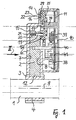
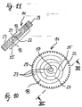
- the illustrated device for locking the steering shaft 1 of a motor vehicle against rotation has a one-piece locking pin 2, which cooperates with groove-shaped locking recesses 3 a mounted on the steering shaft 1 locking sleeve 4.
- the steering shaft 1 and the locking sleeve 4 are enclosed by a non-reproduced jacket tube with a through opening for the Sperrbotzen 2.
- the locking pin 2 has a rectangular cross section and is axially displaceably mounted in a channel 5 corresponding cross section of a housing 6.
- the two wider side surfaces 7, 8 of the channel 5 each extend in a plane perpendicular to the common longitudinal axis 9 of the steering shaft 1 and the coaxial jacket tube to it.
- the housing 6 is provided on the side remote from the channel 5 with a closed by a cover 10 mounting opening 11 and fixed to the jacket tube.
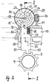
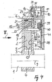
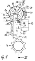
- the locking pin 2 is between the apparent from Fig. 1, 2, 3 blocking position in which it engages with its the steering shaft 1 facing end 12 in a locking recess 3 of the locking sleeve 4, so that the steering shaft 1 can not be rotated, and the From Fig. 4, 5, 6 apparent release position back and forth, in which the locking pin 2 engages with the end 12 in no locking recess 3 of the locking sleeve 4 and the steering shaft 1 releases, so that it can be rotated.
- control member 14 For axial displacement of the locking pin 2 in the release position and in the opposite direction in the blocking position is a back and forth by means of an electric motor 13 with reversible direction of rotation control member 14.
- the control member 14 is on the housing cover 10 facing side of the locking pin 2 adjacent to the steering shaft 1 distant End 15 of the locking pin 2 and rotatably mounted in the housing 6 on a cylindrical projection 16 of the housing 6, which engages in a central bearing bore 17 of the control member 14 and perpendicular to the two wider side surfaces 7, 8 of the locking pin 2 leading channel 5 of Housing 6 extends.
- a spiral groove 18 which wraps around the bearing bore 17 of the control member 14 and in which a laterally projecting from the locking pin 2 pin 19 engages, so that the locking pin 2 during rotation of the control member 14th in one or in the other direction is displaced axially in the one or in the other direction radially to the axis of rotation of the control member 14 defined by the housing projection 16.
- the cylindrical pin 19 is axially displaceably mounted in a provided in the steering spindle remote end 15 of the locking pin 2 cylindrical bore 20 and loaded by a disposed in the bore 20 helical compression spring 21 in the direction of the control member 14.
- the control member 14 has a with the pin 19, as described below, cooperating, from the bottom 22 of the spiral groove 18 to the locking pin 2 facing flat surface 23 of the control member 14 rising inclined surface 24 which extends along the spiral groove 18 and begins at a point explained below 25 of the bottom 22 of the spiral groove 18.
- the locking pin 2 is loaded by a helical compression spring 26 in the direction of the steering shaft 1, which is supported on the one hand on a shoulder 27 of the locking pin 2 and on the other hand on a shoulder 28 of the housing 6
- the control member 14 is formed as a circular disc with a peripheral toothing 29, in which engages a drive screw 30 which is mounted on the output shaft 31 of the electric motor 13, the electric motor 13 is arranged in the housing 6 next to the locking pin 2, so that its output shaft 31 extends parallel to the two narrower side surfaces 32, 33 of the locking pin 2
- the control member 14 is axially fixed on the cylindrical projection 16 of the housing 6 by a cylindrical projection 34 of larger diameter of the housing cover 10 and provided on the locking pin 2 facing away from the end face with a protruding spiral rib 35 which wraps around the bearing bore 17 of the control member 14 and with which in the housing 6 about a parallel to the housing projection 16 axis 36 pivotable, spring-loaded two-armed pivot lever 37 cooperates to an electric switch 38 corresponding both in the locking position of the locking pin 2 corresponding rotational position of the control member 14 and in the release position of the locking pin 2 To operate rotational position of the control member 14.
- Another electrical switch 39 is actuated by a pin-shaped lateral projection 40 of the locking pin 2 when the locking pin 2 assumes its release position.
- the two electrical switches 38, 39 are arranged on a printed circuit board 41 fixed in the housing 6 and parallel to the housing cover 10.
- the electric motor 13 is turned on, so that its output shaft 31 via the drive screw 30, the control member 14 in the direction of the arrow B rotates and the pin 19 of the locking pin 2 moves in the spiral groove 18 of the control member 14 closer and closer to the axis of rotation (bearing bore 17) of the control member 14 moves.
- the electric motor 13 is turned on, so that its output shaft 31 via the drive screw 30, the control member 14 in the direction of the arrow D rotates and the pin 19 of the locking pin 2 moves in the spiral groove 18 of the control member 14 further and further away from the axis of rotation (bearing bore 17) of the control member 14 away.
Landscapes
- Engineering & Computer Science (AREA)
- Mechanical Engineering (AREA)
- Chemical & Material Sciences (AREA)
- Combustion & Propulsion (AREA)
- Transportation (AREA)
- Power Steering Mechanism (AREA)
- Lock And Its Accessories (AREA)
Applications Claiming Priority (3)
| Application Number | Priority Date | Filing Date | Title |
|---|---|---|---|
| DE2003120138 DE10320138B3 (de) | 2003-05-06 | 2003-05-06 | Vorrichtung zum Sperren der Lenkspindel eines Kraftfahrzeugs |
| DE10320138 | 2003-05-06 | ||
| PCT/EP2004/004220 WO2004098961A1 (de) | 2003-05-06 | 2004-04-21 | Vorrichtung zum sperren der lenkspindel eines kraftfahrzeugs |
Publications (2)
| Publication Number | Publication Date |
|---|---|
| EP1558474A1 EP1558474A1 (de) | 2005-08-03 |
| EP1558474B1 true EP1558474B1 (de) | 2006-02-22 |
Family
ID=33426679
Family Applications (1)
| Application Number | Title | Priority Date | Filing Date |
|---|---|---|---|
| EP04728533A Expired - Lifetime EP1558474B1 (de) | 2003-05-06 | 2004-04-21 | Vorrichtung zum sperren der lenkspindel eines kraftfahrzeugs |
Country Status (8)
| Country | Link |
|---|---|
| US (1) | US7363785B2 (zh) |
| EP (1) | EP1558474B1 (zh) |
| JP (1) | JP4448512B2 (zh) |
| KR (1) | KR100789334B1 (zh) |
| CN (1) | CN100349768C (zh) |
| BR (1) | BRPI0405232A (zh) |
| DE (2) | DE10320138B3 (zh) |
| WO (1) | WO2004098961A1 (zh) |
Families Citing this family (33)
| Publication number | Priority date | Publication date | Assignee | Title |
|---|---|---|---|---|
| JP2006507966A (ja) * | 2002-05-23 | 2006-03-09 | メソード・エレクトロニクス・インコーポレーテッド | ステアリングロック装置 |
| DE102004043898B3 (de) * | 2004-09-10 | 2005-12-01 | Huf Hülsbeck & Fürst Gmbh & Co. Kg | Vorrichtung zum Sperren der Lenkspindel eines Kraftfahrzeugs |
| DE102004053438A1 (de) * | 2004-11-05 | 2006-05-11 | Valeo Sicherheitssysteme Gmbh | Lenkschloß |
| JP2006273115A (ja) * | 2005-03-29 | 2006-10-12 | Alpha Corp | 電動ステアリングロック装置及び電動ステアリングロック装置の制御方法 |
| DE102005035439A1 (de) * | 2005-07-28 | 2007-02-01 | Daimlerchrysler Ag | Vorrichtung zum Sperren der Lenkspindel eines Kraftfahrzeugs |
| KR100901626B1 (ko) * | 2007-09-12 | 2009-06-08 | 현대자동차주식회사 | 스티어링 컬럼 록킹장치 |
| DE102007059713A1 (de) * | 2007-12-10 | 2009-06-18 | Huf Hülsbeck & Fürst Gmbh & Co. Kg | Vorrichtung zur Ansteuerung eines Sperrgliedes |
| DE102008016820A1 (de) * | 2008-04-01 | 2009-10-08 | Huf Hülsbeck & Fürst Gmbh & Co. Kg | Vorrichtung zur Ansteuerung einer Sperreinheit |
| US20090302566A1 (en) * | 2008-06-06 | 2009-12-10 | Choi Wan Chan | Foldable Scooter |
| DE102008032585B4 (de) * | 2008-07-11 | 2018-07-19 | Huf Hülsbeck & Fürst Gmbh & Co. Kg | Vorrichtung zur Ansteuerung eines Sperrgliedes |
| CN101824941B (zh) * | 2009-03-06 | 2014-07-09 | 株式会社有信 | 电动转向锁定装置 |
| JP5260358B2 (ja) | 2009-03-06 | 2013-08-14 | 株式会社ユーシン | 電動ステアリングロック装置 |
| FR2952005B1 (fr) * | 2009-11-05 | 2016-03-25 | Valeo Securite Habitacle | Dispositif antivol pour colonne de direction de vehicule a super condamnation assuree par bascule |
| US8424348B2 (en) * | 2010-01-27 | 2013-04-23 | Strattec Security Corporation | Steering lock |
| DE102010037071A1 (de) * | 2010-08-19 | 2012-02-23 | Huf Hülsbeck & Fürst Gmbh & Co. Kg | Vorrichtung zur Verlagerung eines bewegbaren Sperrelementes |
| EP2476592B1 (fr) * | 2011-01-13 | 2020-04-08 | U-Shin Deutschland Zugangssysteme GmbH | Antivol de direction pour véhicule automobile |
| ES2457241T3 (es) * | 2011-01-21 | 2014-04-25 | Valeo Sicherheitssysteme Gmbh | Antirrobo de dirección para vehículo automóvil |
| DE102013217735A1 (de) | 2012-09-07 | 2014-03-13 | Strattec Security Corporation | Lenkschloss |
| EP2716508B1 (en) * | 2012-10-04 | 2015-12-09 | U-Shin Deutschland Zugangssysteme GmbH | Electrical steering column lock for an automative vehicle |
| CN105593078B (zh) * | 2013-10-03 | 2017-09-22 | 株式会社阿尔发 | 转向锁定装置 |
| EP3053787B1 (en) * | 2013-10-04 | 2019-01-30 | Alpha Corporation | Electric steering lock device |
| CN103612484A (zh) * | 2013-10-29 | 2014-03-05 | 格林精密部件(苏州)有限公司 | 蜗杆二维码打标定位机构 |
| US9731681B2 (en) | 2014-04-29 | 2017-08-15 | Strattec Security Corporation | Steering lock |
| DE102014112749A1 (de) * | 2014-09-04 | 2016-03-10 | Huf Hülsbeck & Fürst Gmbh & Co. Kg | Sperrkranzverriegelung |
| DE102014112816A1 (de) * | 2014-09-05 | 2016-03-10 | Huf Hülsbeck & Fürst Gmbh & Co. Kg | Lenkradverriegelung |
| DE102015015221A1 (de) * | 2014-12-01 | 2016-06-02 | Marquardt Gmbh | Verriegelungseinrichtung, insbesondere für ein Kraftfahrzeug |
| CN106143607B (zh) * | 2015-03-31 | 2019-01-29 | 比亚迪股份有限公司 | 转向横拉杆 |
| CN106143591B (zh) * | 2015-03-31 | 2019-03-29 | 比亚迪股份有限公司 | 转向器总成及汽车 |
| EP3103945B1 (en) | 2015-06-10 | 2018-09-12 | HELLA GmbH & Co. KGaA | Vehicle door check |
| DE102016108565A1 (de) * | 2016-05-10 | 2017-11-16 | Huf Hülsbeck & Fürst Gmbh & Co. Kg | Umsetzungselement für eine elektrische Lenkradsperre |
| JP6798459B2 (ja) * | 2017-09-20 | 2020-12-09 | トヨタ自動車株式会社 | ステアリングロック装置 |
| CN110978979A (zh) * | 2019-11-25 | 2020-04-10 | 安徽华海特种电缆集团有限公司 | 一种新能源电池用保护设备 |
| CN118475997A (zh) * | 2022-01-28 | 2024-08-09 | Abb瑞士股份有限公司 | 双电源转换开关 |
Family Cites Families (17)
| Publication number | Priority date | Publication date | Assignee | Title |
|---|---|---|---|---|
| FR348087A (fr) * | 1904-10-31 | 1905-03-31 | Ch Andre Et Cie Soc | Moyen pour supporter horizontalement, sans crainte de dénivellement, les compteurs à gaz |
| US1786186A (en) | 1928-04-19 | 1930-12-23 | Fred E Bauermeister | Steering-shaft lock |
| US2874562A (en) * | 1956-12-11 | 1959-02-24 | Christopher N Cross | Motor vehicle steering wheel lock |
| DE2234182A1 (de) * | 1972-07-12 | 1974-01-31 | Daimler Benz Ag | Lenkschloss fuer fahrzeuge, insbesondere kraftwagen |
| DE4436326C1 (de) * | 1994-10-11 | 1995-10-19 | Huelsbeck & Fuerst | Schloß, insbesondere zum Verriegeln der Lenkspindel oder der Zahnstange des Lenkgetriebes oder der Ausgangswelle des Antriebsgetriebes eines Kraftfahrzeugs |
| FR2788478B1 (fr) * | 1999-01-15 | 2001-04-06 | Valeo Securite Habitacle | Antivol de direction de vehicule automobile |
| FR2788477B1 (fr) * | 1999-01-15 | 2001-02-16 | Valeo Securite Habitacle | Antivol de direction de vehicule automobile |
| FR2799426B1 (fr) * | 1999-09-17 | 2001-12-07 | Valeo Securite Habitacle | Antivol de direction de vehicule automobile |
| DE19961975C1 (de) * | 1999-12-22 | 2000-12-14 | Valeo Deutschland Gmbh & Co | Verriegelungsvorrichtung |
| DE10109609C1 (de) * | 2001-02-28 | 2002-10-10 | Huf Huelsbeck & Fuerst Gmbh | Schloß, insbesondere zum Verriegeln der Lenkspindel eines Kraftfahrzeugs |
| DE10121714C1 (de) * | 2001-05-04 | 2003-01-02 | Huf Huelsbeck & Fuerst Gmbh | Schloß, insbesondere zum Verriegeln der Lenkspindel eines Kraftfahrzeugs |
| JP3811416B2 (ja) * | 2002-03-22 | 2006-08-23 | 株式会社東海理化電機製作所 | 電動ステアリングロック装置 |
| JP3808789B2 (ja) * | 2002-03-22 | 2006-08-16 | 株式会社東海理化電機製作所 | 電動ステアリングロック装置 |
| JP2006507966A (ja) * | 2002-05-23 | 2006-03-09 | メソード・エレクトロニクス・インコーポレーテッド | ステアリングロック装置 |
| DE10247802B3 (de) * | 2002-10-14 | 2004-02-05 | Huf Hülsbeck & Fürst Gmbh & Co. Kg | Vorrichtung zum Sperren der Lenkspindel eines Kraftfahrzeugs |
| DE10247803B3 (de) * | 2002-10-14 | 2004-01-29 | Huf Hülsbeck & Fürst Gmbh & Co. Kg | Vorrichtung zum Sperren der Lenkspindel eines Kraftfahrzeugs |
| US7140213B2 (en) * | 2004-02-21 | 2006-11-28 | Strattec Security Corporation | Steering column lock apparatus and method |
-
2003
- 2003-05-06 DE DE2003120138 patent/DE10320138B3/de not_active Expired - Fee Related
-
2004
- 2004-04-21 CN CNB2004800087921A patent/CN100349768C/zh not_active Expired - Fee Related
- 2004-04-21 EP EP04728533A patent/EP1558474B1/de not_active Expired - Lifetime
- 2004-04-21 BR BRPI0405232 patent/BRPI0405232A/pt not_active IP Right Cessation
- 2004-04-21 WO PCT/EP2004/004220 patent/WO2004098961A1/de active IP Right Grant
- 2004-04-21 DE DE200450000307 patent/DE502004000307D1/de not_active Expired - Lifetime
- 2004-04-21 JP JP2006505215A patent/JP4448512B2/ja not_active Expired - Fee Related
- 2004-04-21 KR KR1020057020903A patent/KR100789334B1/ko not_active IP Right Cessation
- 2004-04-21 US US10/548,312 patent/US7363785B2/en not_active Expired - Fee Related
Also Published As
| Publication number | Publication date |
|---|---|
| US7363785B2 (en) | 2008-04-29 |
| DE10320138B3 (de) | 2005-01-13 |
| KR20060055451A (ko) | 2006-05-23 |
| BRPI0405232A (pt) | 2005-03-15 |
| KR100789334B1 (ko) | 2007-12-28 |
| WO2004098961A1 (de) | 2004-11-18 |
| JP4448512B2 (ja) | 2010-04-14 |
| CN1767971A (zh) | 2006-05-03 |
| EP1558474A1 (de) | 2005-08-03 |
| DE502004000307D1 (de) | 2006-04-27 |
| CN100349768C (zh) | 2007-11-21 |
| JP2006525170A (ja) | 2006-11-09 |
| US20060070414A1 (en) | 2006-04-06 |
Similar Documents
| Publication | Publication Date | Title |
|---|---|---|
| EP1558474B1 (de) | Vorrichtung zum sperren der lenkspindel eines kraftfahrzeugs | |
| DE10320155B3 (de) | Vorrichtung zum Sperren der Lenkspindel eines Kraftfahrzeugs | |
| EP1167134B1 (de) | Schloss, insbesondere zum Verriegeln der Lenkspindel oder der Zahnstange des Lenkgetriebes oder der Ausgangswelle des Antriebsgetriebes eines Kraftfahrzeugs | |
| DE10121714C1 (de) | Schloß, insbesondere zum Verriegeln der Lenkspindel eines Kraftfahrzeugs | |
| EP1236626B1 (de) | Schloss, insbesondere zum Verriegeln der Lenkspindel eines Kraftfahrzeugs | |
| DE10320154B3 (de) | Vorrichtung zum Sperren der Lenkspindel eines Kraftfahrzeugs | |
| DE10247802B3 (de) | Vorrichtung zum Sperren der Lenkspindel eines Kraftfahrzeugs | |
| EP1410963B1 (de) | Vorrichtung zum Sperren der Lenkspindel eines Kraftfahrzeugs | |
| EP1725437B1 (de) | Vorrichtung zum sperren der lenkspindel eines kraftfahrzeugs | |
| EP1225290A2 (de) | Kraftfahrzeugtürverschluss | |
| DE2648818C3 (de) | Drehmomentabhängige Schaltvorrichtung für einen Elektromotor | |
| DE3941352C2 (de) | Elektromotorisches Stellglied | |
| DE3015016C2 (de) | Abschalteinrichtung für die Hilfskraft in einer hydraulischen Hilfkraftzahnstangenlenkung für Fahrzeuge | |
| DE1928788A1 (de) | Betaetigungsvorrichtung mit drehbarem Einstellglied,insbesondere fuer Schalter | |
| DE102005035439A1 (de) | Vorrichtung zum Sperren der Lenkspindel eines Kraftfahrzeugs | |
| DE3726774C2 (de) | Zünd- und Anlaßschalter mit Schleifkontakten zum Anbau an eine Lenkschloßdiebstahlsicherung für Kraftfahrzeuge | |
| DE4225287A1 (de) | Elektrischer Schalter zur Drehzahlregulierung von Motoren | |
| DE19532590A1 (de) | Motor- und handbetätigbarer Stellantrieb | |
| DE202008002354U1 (de) | Feststellvorrichtung für eine verfahrbare Wand | |
| DE102005021050B3 (de) | Vorrichtung zum Sperren der Lenkspindel eines Kraftfahrzeugs | |
| DE3128407C2 (de) | Lenkschloß für Kraftfahrzeuge | |
| DE2651496B2 (de) | Kraftfahrzeug-Lenkschloß | |
| EP0400209A2 (de) | Elektromotorisches Stellelement insbesondere für eine zentrale Türverriegelung | |
| DE9202367U1 (de) | Lenkschloß für Kraftfahrzeuge | |
| DE2364429A1 (de) | Antriebsvorrichtung zum bewegen von fensterscheiben, schiebedaechern und dergleichen von kraftfahrzeugen |
Legal Events
| Date | Code | Title | Description |
|---|---|---|---|
| PUAI | Public reference made under article 153(3) epc to a published international application that has entered the european phase |
Free format text: ORIGINAL CODE: 0009012 |
|
| 17P | Request for examination filed |
Effective date: 20050523 |
|
| AK | Designated contracting states |
Kind code of ref document: A1 Designated state(s): AT BE BG CH CY CZ DE DK EE ES FI FR GB GR HU IE IT LI LU MC NL PL PT RO SE SI SK TR |
|
| AX | Request for extension of the european patent |
Extension state: AL HR LT LV MK |
|
| GRAP | Despatch of communication of intention to grant a patent |
Free format text: ORIGINAL CODE: EPIDOSNIGR1 |
|
| GRAS | Grant fee paid |
Free format text: ORIGINAL CODE: EPIDOSNIGR3 |
|
| GRAA | (expected) grant |
Free format text: ORIGINAL CODE: 0009210 |
|
| DAX | Request for extension of the european patent (deleted) | ||
| RBV | Designated contracting states (corrected) |
Designated state(s): DE ES FR GB IT |
|
| AK | Designated contracting states |
Kind code of ref document: B1 Designated state(s): DE ES FR GB IT |
|
| PG25 | Lapsed in a contracting state [announced via postgrant information from national office to epo] |
Ref country code: GB Free format text: LAPSE BECAUSE OF FAILURE TO SUBMIT A TRANSLATION OF THE DESCRIPTION OR TO PAY THE FEE WITHIN THE PRESCRIBED TIME-LIMIT Effective date: 20060222 |
|
| REG | Reference to a national code |
Ref country code: GB Ref legal event code: FG4D Free format text: NOT ENGLISH |
|
| REF | Corresponds to: |
Ref document number: 502004000307 Country of ref document: DE Date of ref document: 20060427 Kind code of ref document: P |
|
| PG25 | Lapsed in a contracting state [announced via postgrant information from national office to epo] |
Ref country code: ES Free format text: LAPSE BECAUSE OF FAILURE TO SUBMIT A TRANSLATION OF THE DESCRIPTION OR TO PAY THE FEE WITHIN THE PRESCRIBED TIME-LIMIT Effective date: 20060602 |
|
| ET | Fr: translation filed | ||
| GBV | Gb: ep patent (uk) treated as always having been void in accordance with gb section 77(7)/1977 [no translation filed] |
Effective date: 20060222 |
|
| PLBE | No opposition filed within time limit |
Free format text: ORIGINAL CODE: 0009261 |
|
| STAA | Information on the status of an ep patent application or granted ep patent |
Free format text: STATUS: NO OPPOSITION FILED WITHIN TIME LIMIT |
|
| 26N | No opposition filed |
Effective date: 20061123 |
|
| PGFP | Annual fee paid to national office [announced via postgrant information from national office to epo] |
Ref country code: IT Payment date: 20090429 Year of fee payment: 6 |
|
| PG25 | Lapsed in a contracting state [announced via postgrant information from national office to epo] |
Ref country code: IT Free format text: LAPSE BECAUSE OF NON-PAYMENT OF DUE FEES Effective date: 20100421 |
|
| PGFP | Annual fee paid to national office [announced via postgrant information from national office to epo] |
Ref country code: FR Payment date: 20130523 Year of fee payment: 10 |
|
| REG | Reference to a national code |
Ref country code: DE Ref legal event code: R084 Ref document number: 502004000307 Country of ref document: DE Effective date: 20140530 |
|
| REG | Reference to a national code |
Ref country code: FR Ref legal event code: ST Effective date: 20141231 |
|
| PG25 | Lapsed in a contracting state [announced via postgrant information from national office to epo] |
Ref country code: FR Free format text: LAPSE BECAUSE OF NON-PAYMENT OF DUE FEES Effective date: 20140430 |
|
| PGFP | Annual fee paid to national office [announced via postgrant information from national office to epo] |
Ref country code: DE Payment date: 20200423 Year of fee payment: 17 |
|
| REG | Reference to a national code |
Ref country code: DE Ref legal event code: R119 Ref document number: 502004000307 Country of ref document: DE |
|
| PG25 | Lapsed in a contracting state [announced via postgrant information from national office to epo] |
Ref country code: DE Free format text: LAPSE BECAUSE OF NON-PAYMENT OF DUE FEES Effective date: 20211103 |