EP1558474B1 - Blocking device for a motor vehicle steering shaft - Google Patents
Blocking device for a motor vehicle steering shaft Download PDFInfo
- Publication number
- EP1558474B1 EP1558474B1 EP04728533A EP04728533A EP1558474B1 EP 1558474 B1 EP1558474 B1 EP 1558474B1 EP 04728533 A EP04728533 A EP 04728533A EP 04728533 A EP04728533 A EP 04728533A EP 1558474 B1 EP1558474 B1 EP 1558474B1
- Authority
- EP
- European Patent Office
- Prior art keywords
- control member
- locking
- locking bolt
- pin
- locking pin
- Prior art date
- Legal status (The legal status is an assumption and is not a legal conclusion. Google has not performed a legal analysis and makes no representation as to the accuracy of the status listed.)
- Expired - Lifetime
Links
- 230000000903 blocking effect Effects 0.000 title description 5
- 230000002441 reversible effect Effects 0.000 claims description 2
- 230000000630 rising effect Effects 0.000 claims description 2
- 230000006835 compression Effects 0.000 description 7
- 238000007906 compression Methods 0.000 description 7
- 238000006073 displacement reaction Methods 0.000 description 2
- 230000002093 peripheral effect Effects 0.000 description 1
Images


Classifications
-
- B—PERFORMING OPERATIONS; TRANSPORTING
- B60—VEHICLES IN GENERAL
- B60R—VEHICLES, VEHICLE FITTINGS, OR VEHICLE PARTS, NOT OTHERWISE PROVIDED FOR
- B60R25/00—Fittings or systems for preventing or indicating unauthorised use or theft of vehicles
- B60R25/01—Fittings or systems for preventing or indicating unauthorised use or theft of vehicles operating on vehicle systems or fittings, e.g. on doors, seats or windscreens
- B60R25/02—Fittings or systems for preventing or indicating unauthorised use or theft of vehicles operating on vehicle systems or fittings, e.g. on doors, seats or windscreens operating on the steering mechanism
- B60R25/021—Fittings or systems for preventing or indicating unauthorised use or theft of vehicles operating on vehicle systems or fittings, e.g. on doors, seats or windscreens operating on the steering mechanism restraining movement of the steering column or steering wheel hub, e.g. restraining means controlled by ignition switch
- B60R25/0215—Fittings or systems for preventing or indicating unauthorised use or theft of vehicles operating on vehicle systems or fittings, e.g. on doors, seats or windscreens operating on the steering mechanism restraining movement of the steering column or steering wheel hub, e.g. restraining means controlled by ignition switch using electric means, e.g. electric motors or solenoids
- B60R25/02153—Fittings or systems for preventing or indicating unauthorised use or theft of vehicles operating on vehicle systems or fittings, e.g. on doors, seats or windscreens operating on the steering mechanism restraining movement of the steering column or steering wheel hub, e.g. restraining means controlled by ignition switch using electric means, e.g. electric motors or solenoids comprising a locking member radially and linearly moved towards the steering column
-
- B—PERFORMING OPERATIONS; TRANSPORTING
- B60—VEHICLES IN GENERAL
- B60R—VEHICLES, VEHICLE FITTINGS, OR VEHICLE PARTS, NOT OTHERWISE PROVIDED FOR
- B60R25/00—Fittings or systems for preventing or indicating unauthorised use or theft of vehicles
- B60R25/01—Fittings or systems for preventing or indicating unauthorised use or theft of vehicles operating on vehicle systems or fittings, e.g. on doors, seats or windscreens
- B60R25/02—Fittings or systems for preventing or indicating unauthorised use or theft of vehicles operating on vehicle systems or fittings, e.g. on doors, seats or windscreens operating on the steering mechanism
- B60R25/022—Fittings or systems for preventing or indicating unauthorised use or theft of vehicles operating on vehicle systems or fittings, e.g. on doors, seats or windscreens operating on the steering mechanism operating on the steering wheel, e.g. bars locked to the steering wheel rim
-
- B—PERFORMING OPERATIONS; TRANSPORTING
- B60—VEHICLES IN GENERAL
- B60R—VEHICLES, VEHICLE FITTINGS, OR VEHICLE PARTS, NOT OTHERWISE PROVIDED FOR
- B60R25/00—Fittings or systems for preventing or indicating unauthorised use or theft of vehicles
- B60R25/01—Fittings or systems for preventing or indicating unauthorised use or theft of vehicles operating on vehicle systems or fittings, e.g. on doors, seats or windscreens
- B60R25/04—Fittings or systems for preventing or indicating unauthorised use or theft of vehicles operating on vehicle systems or fittings, e.g. on doors, seats or windscreens operating on the propulsion system, e.g. engine or drive motor
-
- B—PERFORMING OPERATIONS; TRANSPORTING
- B62—LAND VEHICLES FOR TRAVELLING OTHERWISE THAN ON RAILS
- B62D—MOTOR VEHICLES; TRAILERS
- B62D1/00—Steering controls, i.e. means for initiating a change of direction of the vehicle
- B62D1/02—Steering controls, i.e. means for initiating a change of direction of the vehicle vehicle-mounted
- B62D1/16—Steering columns
-
- Y—GENERAL TAGGING OF NEW TECHNOLOGICAL DEVELOPMENTS; GENERAL TAGGING OF CROSS-SECTIONAL TECHNOLOGIES SPANNING OVER SEVERAL SECTIONS OF THE IPC; TECHNICAL SUBJECTS COVERED BY FORMER USPC CROSS-REFERENCE ART COLLECTIONS [XRACs] AND DIGESTS
- Y10—TECHNICAL SUBJECTS COVERED BY FORMER USPC
- Y10T—TECHNICAL SUBJECTS COVERED BY FORMER US CLASSIFICATION
- Y10T70/00—Locks
- Y10T70/50—Special application
- Y10T70/5611—For control and machine elements
- Y10T70/5646—Rotary shaft
- Y10T70/565—Locked stationary
- Y10T70/5655—Housing-carried lock
- Y10T70/5664—Latching bolt
-
- Y—GENERAL TAGGING OF NEW TECHNOLOGICAL DEVELOPMENTS; GENERAL TAGGING OF CROSS-SECTIONAL TECHNOLOGIES SPANNING OVER SEVERAL SECTIONS OF THE IPC; TECHNICAL SUBJECTS COVERED BY FORMER USPC CROSS-REFERENCE ART COLLECTIONS [XRACs] AND DIGESTS
- Y10—TECHNICAL SUBJECTS COVERED BY FORMER USPC
- Y10T—TECHNICAL SUBJECTS COVERED BY FORMER US CLASSIFICATION
- Y10T70/00—Locks
- Y10T70/50—Special application
- Y10T70/5889—For automotive vehicles
- Y10T70/5956—Steering mechanism with switch
Definitions
- the invention relates to a device for locking the steering shaft of a motor vehicle against rotation by means cooperating with a locking recesses of the steering shaft locking pin, which is back and forth with the aid of a reciprocating control member radially to the axis of rotation of the control member between a locking position and a release position and engages with a laterally projecting pin in a spiral groove of the control member, which winds on the locking pin adjacent to the front side of the control member about its axis of rotation.
- the locking pin is formed in two parts and provided with a helical compression spring against the action of cooperating with the locking recesses of the steering shaft locking pin part and cooperating with the control member locking pin part can be pushed together when the control member is rotated to the blocking position of the locking pin corresponding position with
- the steering shaft cooperating locking pin part can enter into no locking recess of the steering shaft, because the steering shaft is not in such a rotational position in which one of its locking recesses is aligned with this locking pin part.
- the provided on the other locking pin part, engaging in the spiral groove of the control member pin represents a fixed lateral projection of this locking pin part.
- the control member is formed as a circular disc, which can be rotated back and forth by means of a lock cylinder.
- the two-piece locking pin training with Helical compression spring is relatively expensive and prone to failure (DE-A-506 781).
- a one-piece locking pin is provided, the laterally projecting pin is fixedly connected to the locking pin and extends through a spiral slot of a circular control disc, which are reciprocated back and forth by means of a lock cylinder can.
- the control disk can only be rotated to the position corresponding to the locking position of the locking bolt when a locking recess of the steering shaft is aligned with the locking pin and the locking pin can enter the locking recess to take its blocking position (US-A-1 786 186).
- the invention has for its object to provide a device of the type described above, which is characterized by a simple in every respect as well as inexpensive locking bolt low-susceptible interference, the control member can always be rotated in the locking position of the locking pin corresponding position, regardless of the respective rotational position of the steering spindle.
- the illustrated device for locking the steering shaft 1 of a motor vehicle against rotation has a one-piece locking pin 2, which cooperates with groove-shaped locking recesses 3 a mounted on the steering shaft 1 locking sleeve 4.
- the steering shaft 1 and the locking sleeve 4 are enclosed by a non-reproduced jacket tube with a through opening for the Sperrbotzen 2.
- the locking pin 2 has a rectangular cross section and is axially displaceably mounted in a channel 5 corresponding cross section of a housing 6.
- the two wider side surfaces 7, 8 of the channel 5 each extend in a plane perpendicular to the common longitudinal axis 9 of the steering shaft 1 and the coaxial jacket tube to it.
- the housing 6 is provided on the side remote from the channel 5 with a closed by a cover 10 mounting opening 11 and fixed to the jacket tube.
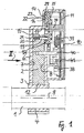
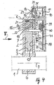
- the locking pin 2 is between the apparent from Fig. 1, 2, 3 blocking position in which it engages with its the steering shaft 1 facing end 12 in a locking recess 3 of the locking sleeve 4, so that the steering shaft 1 can not be rotated, and the From Fig. 4, 5, 6 apparent release position back and forth, in which the locking pin 2 engages with the end 12 in no locking recess 3 of the locking sleeve 4 and the steering shaft 1 releases, so that it can be rotated.
- control member 14 For axial displacement of the locking pin 2 in the release position and in the opposite direction in the blocking position is a back and forth by means of an electric motor 13 with reversible direction of rotation control member 14.
- the control member 14 is on the housing cover 10 facing side of the locking pin 2 adjacent to the steering shaft 1 distant End 15 of the locking pin 2 and rotatably mounted in the housing 6 on a cylindrical projection 16 of the housing 6, which engages in a central bearing bore 17 of the control member 14 and perpendicular to the two wider side surfaces 7, 8 of the locking pin 2 leading channel 5 of Housing 6 extends.
- a spiral groove 18 which wraps around the bearing bore 17 of the control member 14 and in which a laterally projecting from the locking pin 2 pin 19 engages, so that the locking pin 2 during rotation of the control member 14th in one or in the other direction is displaced axially in the one or in the other direction radially to the axis of rotation of the control member 14 defined by the housing projection 16.
- the cylindrical pin 19 is axially displaceably mounted in a provided in the steering spindle remote end 15 of the locking pin 2 cylindrical bore 20 and loaded by a disposed in the bore 20 helical compression spring 21 in the direction of the control member 14.
- the control member 14 has a with the pin 19, as described below, cooperating, from the bottom 22 of the spiral groove 18 to the locking pin 2 facing flat surface 23 of the control member 14 rising inclined surface 24 which extends along the spiral groove 18 and begins at a point explained below 25 of the bottom 22 of the spiral groove 18.
- the locking pin 2 is loaded by a helical compression spring 26 in the direction of the steering shaft 1, which is supported on the one hand on a shoulder 27 of the locking pin 2 and on the other hand on a shoulder 28 of the housing 6
- the control member 14 is formed as a circular disc with a peripheral toothing 29, in which engages a drive screw 30 which is mounted on the output shaft 31 of the electric motor 13, the electric motor 13 is arranged in the housing 6 next to the locking pin 2, so that its output shaft 31 extends parallel to the two narrower side surfaces 32, 33 of the locking pin 2
- the control member 14 is axially fixed on the cylindrical projection 16 of the housing 6 by a cylindrical projection 34 of larger diameter of the housing cover 10 and provided on the locking pin 2 facing away from the end face with a protruding spiral rib 35 which wraps around the bearing bore 17 of the control member 14 and with which in the housing 6 about a parallel to the housing projection 16 axis 36 pivotable, spring-loaded two-armed pivot lever 37 cooperates to an electric switch 38 corresponding both in the locking position of the locking pin 2 corresponding rotational position of the control member 14 and in the release position of the locking pin 2 To operate rotational position of the control member 14.
- Another electrical switch 39 is actuated by a pin-shaped lateral projection 40 of the locking pin 2 when the locking pin 2 assumes its release position.
- the two electrical switches 38, 39 are arranged on a printed circuit board 41 fixed in the housing 6 and parallel to the housing cover 10.
- the electric motor 13 is turned on, so that its output shaft 31 via the drive screw 30, the control member 14 in the direction of the arrow B rotates and the pin 19 of the locking pin 2 moves in the spiral groove 18 of the control member 14 closer and closer to the axis of rotation (bearing bore 17) of the control member 14 moves.
- the electric motor 13 is turned on, so that its output shaft 31 via the drive screw 30, the control member 14 in the direction of the arrow D rotates and the pin 19 of the locking pin 2 moves in the spiral groove 18 of the control member 14 further and further away from the axis of rotation (bearing bore 17) of the control member 14 away.
Description
Die Erfindung bezieht sich auf eine Vorrichtung zum Sperren der Lenkspindel eines Kraftfahrzeugs gegen Drehen mittels eines mit Sperrausnehmungen der Lenkspindel zusammenwirkenden Sperrbolzens, welcher mit Hilfe eines hin-und herdrehbaren Steuergliedes radial zur Drehachse des Steuergliedes zwischen einer Sperrstellung und einer Freigabestellung hin- und herschiebbar ist und mit einem seitlich abstehenden Stift in eine Spiralnut des Steuergliedes eingreift, die sich auf der dem Sperrbolzen benachbarten Stirnseite des Steuerglieds um dessen Drehachse windet.The invention relates to a device for locking the steering shaft of a motor vehicle against rotation by means cooperating with a locking recesses of the steering shaft locking pin, which is back and forth with the aid of a reciprocating control member radially to the axis of rotation of the control member between a locking position and a release position and engages with a laterally projecting pin in a spiral groove of the control member, which winds on the locking pin adjacent to the front side of the control member about its axis of rotation.
Eine derartige Vorrichtung zur Verriegelung der Lenkspindel eines Kraftfahrzeugs, so daß sie nicht mehr gedreht werden kann, ist bekannt. Dabei ist der Sperrbolzen zweiteilig ausgebildet und mit einer Schraubendruckfeder versehen, gegen deren Wirkung der mit den Sperrausnehmungen der Lenkspindel zusammenwirkende Sperrbolzenteil und der mit dem Steuerglied zusammenwirkende Sperrbolzenteil zusammengeschoben werden können, wenn das Steuerglied in die der Sperrstellung des Sperrbolzens entsprechende Stellung gedreht wird, der mit der Lenkspindel zusammenwirkende Sperrbolzenteil aber in keine Sperrausnehmung der Lenkspindel eintreten kann, weil die Lenkspindel sich nicht in einer solchen Drehstellung befindet, in welcher eine ihrer Sperrausnehmungen auf diesen Sperrbolzenteil ausgerichtet ist. Der am anderen Sperrbolzenteil vorgesehene, in die Spiralnut des Steuergliedes eingreifende Stift stellt einen unbeweglichen seitlichen Vorsprung dieses Sperrbolzenteils dar. Das Steuerglied ist als kreisrunde Scheibe ausgebildet, welche mit Hilfe eines Schließzylinders hin- und hergedreht werden kann. Die zweiteilige Sperrbolzenausbildung mit Schraubendruckfeder ist verhältnismäßig aufwendig und störanfällig (DE-A-506 781).Such a device for locking the steering shaft of a motor vehicle so that it can not be rotated, is known. In this case, the locking pin is formed in two parts and provided with a helical compression spring against the action of cooperating with the locking recesses of the steering shaft locking pin part and cooperating with the control member locking pin part can be pushed together when the control member is rotated to the blocking position of the locking pin corresponding position with However, the steering shaft cooperating locking pin part can enter into no locking recess of the steering shaft, because the steering shaft is not in such a rotational position in which one of its locking recesses is aligned with this locking pin part. The provided on the other locking pin part, engaging in the spiral groove of the control member pin represents a fixed lateral projection of this locking pin part. The control member is formed as a circular disc, which can be rotated back and forth by means of a lock cylinder. The two-piece locking pin training with Helical compression spring is relatively expensive and prone to failure (DE-A-506 781).
Bei einer ähnlichen bekannten Vorrichtung zum Sperren der Lenkspindel eines Kraftfahrzeugs gegen Drehen ist ein einteiliger Sperrbolzen vorgesehen, dessen seitlich abstehender Stift mit dem Sperrbolzen fest verbunden ist und sich durch einen spiralförmigen Schlitz einer kreisrunden Steuerscheibe hindurch erstreckt, welche mittels eines Schließzylinders hin- und hergedreht werden kann. Die Steuerscheibe kann nur dann in die der Sperrstellung des Sperrbolzens entsprechende Stellung gedreht werden, wenn eine Sperrausnehmung der Lenkspindel auf den Sperrbolzen ausgerichtet ist und der Sperrbolzen in die Sperrausnehmung eintreten kann, um seine Sperrstellung einzunehmen (US-A-1 786 186).In a similar known device for locking the steering spindle of a motor vehicle against rotation, a one-piece locking pin is provided, the laterally projecting pin is fixedly connected to the locking pin and extends through a spiral slot of a circular control disc, which are reciprocated back and forth by means of a lock cylinder can. The control disk can only be rotated to the position corresponding to the locking position of the locking bolt when a locking recess of the steering shaft is aligned with the locking pin and the locking pin can enter the locking recess to take its blocking position (US-A-1 786 186).
Der Erfindung liegt die Aufgabe zugrunde, eine Vorrichtung der eingangs angegebenen Art zu schaffen, welche sich durch einen in jeder Hinsicht einfachen sowie kostengünstigen Sperrbolzen geringsmöglicher Störanfälligkeit auszeichnet, wobei das Steuerglied dennoch stets in die der Sperrstellung des Sperrbolzens entsprechende Stellung gedreht werden kann, unabhängig von der jeweiligen Drehstellung der Lenkspindel.The invention has for its object to provide a device of the type described above, which is characterized by a simple in every respect as well as inexpensive locking bolt low-susceptible interference, the control member can always be rotated in the locking position of the locking pin corresponding position, regardless of the respective rotational position of the steering spindle.
Diese Aufgabe ist bei einer gattungsgemäßen Vorrichtung erfindungsgemäß durch die im kennzeichnenden Teil des Patentanspruchs 1 aufgeführten Merkmale gelöst Vorteilhafte Ausgestaltungen der Vorrichtung nach der Erfindung sind in den restlichen Patentansprüchen angegeben.This object is achieved according to the invention in a generic device by the features listed in the characterizing part of
Nachstehend ist eine bevorzugte Ausführungsform der erfindungsgemäßen Vorrichtung zum Sperren der Lenkspindel eines Kraftfahrzeugs gegen Drehen anhand von Zeichnungen beispielsweise beschrieben. Darin zeigt:
- Fig. 1 den Längsschnitt entlang der Linie I-I in Fig. 2, wobei der Sperrbolzen sich in seiner Sperrstellung befindet;
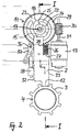
- Fig. 2 die Ansicht in Richtung des Pfeils II in Fig. 1 ohne Gehäuse, Gehäusedeckel sowie Leiterplatte und ohne Lenkspindel;
- Fig. 3 eine der Ansicht von Fig. 2 entsprechende perspektivische Darstellung, wobei der Sperrbolzen längsgeschnitten ist;
- Fig. 4 den Längsschnitt entlang der Linie IV-IV in Fig. 5, wobei der Sperrbolzen sich in seiner Freigabestellung befindet;
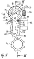
- Fig. 5 die Ansicht in Richtung des Pfeils V in Fig. 4 ohne Gehäuse, Gehäusedeckel sowie Leiterplatte und ohne Lenkspindel;
- Fig. 6 eine der Ansicht von Fig. 5 entsprechende perspektivische Darstellung, wobei der Sperrbolzen längsgeschnitten ist;
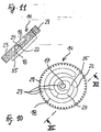
- Fig. 7 den Längsschnitt entlang der Linie VII VII in Fig. 8, wobei der Sperrbolzen sich in einer Vorsperrstellung befindet;
- Fig. 8 die Ansicht in Richtung des Pfeils VIII in Fig. 7 ohne Gehäuse, Gehäusedeckel sowie Leiterplatte und ohne Lenkspindel;
- Fig. 9 eine der Ansicht von Fig. 8 entsprechende perspektivische Darstellung, wobei der Sperrbolzen längsgeschnitten ist;
- Fig. 10 eine Draufsicht auf die mit einer Spiralnut versehene Stirnseite des Steuergliedes;
- Fig. 11 den Schnitt entlang der Linie XI-XI in Fig. 10.
- Figure 1 is a longitudinal section along the line II in Figure 2, wherein the locking pin is in its locking position ..;
- 2 shows the view in the direction of the arrow II in Figure 1 without housing, housing cover and circuit board and without steering shaft.
- Fig. 3 is a view corresponding to the view of Figure 2 perspective view, wherein the locking pin is cut longitudinal;
- 4 shows the longitudinal section along the line IV-IV in Figure 5, wherein the locking pin is in its release position ..;
- 5 shows the view in the direction of arrow V in Figure 4 without housing, housing cover and circuit board and without steering shaft.
- Fig. 6 is a view corresponding to the view of Figure 5 perspective view, wherein the locking pin is cut longitudinal;
- 7 shows the longitudinal section along the line VII VII in Figure 8, wherein the locking pin is in a Vorsperrstellung.
- 8 shows the view in the direction of the arrow VIII in Figure 7 without housing, housing cover and circuit board and without steering shaft.
- Fig. 9 is a perspective view similar to Fig. 8, with the locking pin cut longitudinally;
- Fig. 10 is a plan view of the provided with a spiral groove end face of the control member;
- 11 shows the section along the line XI-XI in FIG. 10.
Die dargestellte Vorrichtung zum Sperren der Lenkspindel 1 eines Kraftfahrzeugs gegen Drehen weist einen einteiligen Sperrbolzen 2 auf, welcher mit nutenförmigen Sperrausnehmungen 3 einer auf der Lenkspindel 1 befestigten Sperrhülse 4 zusammenwirkt. Die Lenkspindel 1 und die Sperrhülse 4 sind von einem nicht wiedergegebenen Mantelrohr mit einer Durchgängsöffnung für den Sperrbotzen 2 umschlossen.The illustrated device for locking the
Der Sperrbolzen 2 weist einen rechteckigen Querschnitt auf und ist in einem Kanal 5 entsprechenden Querschnitts eines Gehäuses 6 axial verschieblich gelagert. Die beiden breiteren Seitenflächen 7, 8 des Kanals 5 erstrecken sich jeweils in einer zur gemeinsamen Längsachse 9 der Lenkspindel 1 und des dazu koaxialen Mantelrohres senkrechten Ebene. Das Gehäuse 6 ist auf der dem Kanal 5 fernen Seite mit einer durch einen Deckel 10 verschlossenen Montageöffnung 11 versehen und am Mantelrohr befestigt.The
Der Sperrbolzen 2 ist zwischen der aus Fig. 1, 2, 3 ersichtlichen Sperrstellung, in welcher er mit seinem der Lenkspindel 1 zugewandten Ende 12 in eine Sperrausnehmung 3 der Sperrhülse 4 eingreift, so daß die Lenkspindel 1 nicht mehr gedreht werden kann, und der aus Fig. 4, 5, 6 ersichtlichen Freigabestellung hin- und herbewegbar, in welcher der Sperrbolzen 2 mit dem Ende 12 in keine Sperrausnehmung 3 der Sperrhülse 4 eingreift und die Lenkspindel 1 freigibt, so daß sie gedreht werden kann.The
Zur Axialverschiebung des Sperrbolzens 2 in die Freigabestellung und in der entgegensetzten Richtung in die Sperrstellung dient ein mittels eines Elektromotors 13 mit umkehrbarer Drehrichtung hin- und herdrehbares Steuerglied 14. Das Steuerglied 14 ist auf der dem Gehäusedeckel 10 zugewandten Seite des Sperrbolzens 2 neben dem der Lenkspindel 1 fernen Ende 15 des Sperrbolzens 2 angeordnet und im Gehäuse 6 auf einem zylindrischen Vorsprung 16 des Gehäuses 6 drehbar gelagert, welcher in eine mittige Lagerbohrung 17 des Steuergliedes 14 eingreift und sich senkrecht zu den beiden breiteren Seitenflächen 7, 8 des den Sperrbolzen 2 führenden Kanals 5 des Gehäuses 6 erstreckt.For axial displacement of the
Auf der dem Sperrbolzen 2 benachbarten Stirnseite ist das Steuerglied 14 mit einer Spiralnut 18 versehen, welche sich um die Lagerbohrung 17 des Steuerglieds 14 herumwindet und in welche ein vom Sperrbolzen 2 seitlich abstehender Stift 19 eingreift, so daß der Sperrbolzen 2 beim Drehen des Steuergliedes 14 in der einen oder in der anderen Richtung radial zu der vom Gehäusevorsprung 16 definierten Drehachse des Steuergliedes 14 in der einen bzw. in der anderen Richtung axial verschoben wird.On the
Der zylindrische Stift 19 ist in einer im lenkspindelfernen Ende 15 des Sperrbolzens 2 vorgesehenen zylindrischen Bohrung 20 axial verschieblich gelagert und durch eine in der Bohrung 20 angeordnete Schraubendruckfeder 21 in Richtung auf das Steuerglied 14 belastet. Das Steuerglied 14 weist eine mit dem Stift 19 so, wie weiter unten beschrieben, zusammenwirkende, vom Boden 22 der Spiralnut 18 zu der dem Sperrbolzen 2 zugewandten ebenen Oberfläche 23 des Steuergliedes 14 ansteigende Schrägfläche 24 auf, welche sich an der Spiralnut 18 entlang erstreckt und an einer weiter unten erläuterten Stelle 25 des Bodens 22 der Spiralnut 18 beginnt. Der Sperrbolzen 2 ist durch eine Schraubendruckfeder 26 in Richtung auf die Lenkspindel 1 belastet, welche sich einerseits an einer Schulter 27 des Sperrbolzens 2 und andererseits an einer Schulter 28 des Gehäuses 6 abstütztThe
Das Steuerglied 14 ist als kreisrunde Scheibe mit einer Umfangsverzahnung 29 ausgebildet, in welche eine Antriebsschnecke 30 eingreift, die auf der Ausgangswelle 31 des Elektromotors 13 befestigt ist Der Elektromotor 13 ist im Gehäuse 6 neben dem Sperrbolzen 2 angeordnet, so daß seine Ausgangswelle 31 sich parallel zu den beiden schmaleren Seitenflächen 32, 33 des Sperrbolzens 2 erstrecktThe
Das Steuerglied 14 ist auf dem zylindrischen Vorsprung 16 des Gehäuses 6 durch einen zylindrischen Vorsprung 34 größeren Durchmessers des Gehäusedeckels 10 axial fixiert und auf der dem Sperrbolzen 2 abgewandten Stirnseite mit einer vorstehenden Spiralrippe 35 versehen, welche sich um die Lagerbohrung 17 des Steuergliedes 14 herumwindet und mit welcher ein im Gehäuse 6 um eine zum Gehäusevorsprung 16 parallele Achse 36 verschwenkbarer, federbelasteter zweiarmiger Schwenkhebel 37 zusammenwirkt, um einen elektrischen Schalter 38 sowohl in der der Sperrstellung des Sperrbolzens 2 entsprechenden Drehstellung des Steuergliedes 14 als auch in der der Freigabestellung des Sperrbolzens 2 entsprechenden Drehstellung des Steuergliedes 14 zu betätigen. Ein weiterer elektrischer Schalter 39 wird von einem stiftförmigen seitlichen Vorsprung 40 des Sperrbolzens 2 betätigt, wenn der Sperrbolzen 2 seine Freigabestellung einnimmt. Die beiden elektrischen Schalter 38, 39 sind an einer im Gehäuse 6 befestigten, zum Gehäusedeckel 10 parallelen Leiterplatte 41 angeordnet.The
Die Funktionsweise der geschilderten Vorrichtung zum Sperren der Lenkspindel 1 gegen Drehen ergibt sich besonders deutlich aus Fig. 3, 6, 9.The operation of the described device for locking the
Um den einteiligen Sperrbolzen 2 axial aus der Sperrstellung gemäß Fig. 3 in Richtung des Pfeils A in die Freigabestellung nach Fig. 6 zu verschieben, wird der Elektromotor 13 eingeschaltet, so daß seine Ausgangswelle 31 über die Antriebsschnecke 30 das Steuerglied 14 in Richtung des Pfeils B dreht und der Stift 19 des Sperrbolzens 2 sich in der Spiralnut 18 des Steuergliedes 14 immer näher zur Drehachse (Lagerbohrung 17) des Steuergliedes 14 bewegt.To move the one-
Um den einteiligen Sperrbolzen 2 axial aus der Freigabestellung gemäß Fig. 6 in Richtung des Pfeils C in die Sperrstellung nach Fig. 3 zu verschieben, wird der Elektromotor 13 eingeschaltet, so daß seine Ausgangswelle 31 über die Antriebsschnecke 30 das Steuerglied 14 in Richtung des Pfeils D dreht und der Stift 19 des Sperrbolzens 2 sich in der Spiralnut 18 des Steuergliedes 14 immer weiter von der Drehachse (Lagerbohrung 17) des Steuergliedes 14 weg bewegt.To move the one-
Wenn beim Drehen des Steuergliedes 14 in Richtung des Pfeils D dem einteiligen Sperrbolzen 2 bzw. dem lenkspindelseitigen Ende 12 desselben keine Sperrausnehmung 3 der Lenkspindel 1 bzw. der Sperrhülse 4 derselben gegenüberliegt, dann kann der Sperrbolzen 2 bzw. das Ende 12 desselben nicht in eine Sperrausnehmung 3 eintreten und der Sperrbolzen 2 nicht in seine Sperrstellung laufen, sondern nur in die Vorsperrstellung nach Fig. 9. Sobald der Sperrbolzen 2 bei seiner Axialverschiebung in Richtung des Pfeils C diese Vorsperrstellung erreicht, liegt der Stift 19 des Sperrbolzens 2 mit seinem freien Ende an der Stelle 25 des Bodens 22 der Spiralnut 18 des Steuergliedes 14 an. Beim weiteren Drehen des Steuerglieds 14 in Richtung des Pfeils D gleitet der Stift 19 mit seinem freien Ende an der Schrägfläche 24 des Steuergliedes 14 entlang auf die dem Sperrbolzen 2 zugewandte ebene Oberfläche 23 des Steuergliedes 14, um entgegen der Wirkung der Schraubendruckfeder 21 in die Bohrung 20 des Sperrbolzens 2 zurückzulaufen und die Spiralnut 18 des Steuergliedes 14 zu verlassen, so daß das Steuerglied 14 in Richtung des Pfeils D bis in die der Sperrstellung des Sperrbolzens 2 entsprechende Stellung weitergedreht werden kann, wie in Fig. 9 dargestellt ist.When turning the
Aus der Vorsperrstellung nach Fig. 9 gelangt der einteilige Sperrbolzen 2 unter der Wirkung seiner Schraubendruckfeder 26 ohne weiteres in die Sperrstellung nach Fig. 3, wenn die Lenkspindel 1 mit der Sperrhülse 4 aus der Stellung gemäß Fig. 9 in die Stellung gemäß Fig. 3 gedreht wird, in welcher eine Sperrausnehmung 3 der Sperrhülse 4 auf das benachbarte Ende 12 des Sperrbolzens 2 ausgerichtet ist. Der Stift 19 des Sperrbolzens 2 gleitet dabei mit seinem freien Ende auf der ebenen Oberfläche 23 des Steuergliedes 14, um schließlich durch seine Schraubendruckfeder 21 wieder aus der Bohrung 20 des Sperrbolzens 2 in Eingriff mit der Spiralnut 18 des Steuergliedes 14 vorgeschoben zu werden.From the Vorsperrstellung of FIG. 9 of the one-
Claims (6)
- Device for locking the steering spindle (1) of a motor vehicle against rotation by means of a locking bolt (2), which cooperates with locking recesses (3) of the steering spindle (1), and which, with the aid of a control member (14), which is rotatable to and fro, can be moved radially to and fro relative to the axis of rotation of the control member (14) between a locking position and a release position and, with a laterally-protruding pin (19), engages a spiral groove (18) of the control member (14), which groove winds around the axis of rotation of the control member (14) on the end face of the control member (14) adjacent to the locking bolt (2),
characterised by
a one-piece locking bolt (2), the pin (19) of which is supported in a movable manner in the locking bolt (2) and spring-loaded towards the control member (14), which has an inclined surface (24) cooperating with the pin (19) and rising from the bottom (22) of the spiral groove (18) of the control member (14) to the flat surface (23) thereof facing towards the locking bolt (2), so that the pin (19) of the locking bolt (2) can leave the spiral groove (18) of the control member (14) against the action of its spring loading (21), and the control member (14) can be rotated into the position corresponding to the locking position of the locking bolt (2), even if no locking recess (3) of the steering spindle (1) is located in front of the locking bolt (2), and the locking bolt cannot move into its locking position. - Device according to claim 1,
characterised in that
the inclined surface (24) of the control member (14) extends along the spiral groove (18) of the control member (14) and begins at the point (25) on the bottom (22) of the spiral groove (18), at which the pin (19) of the locking bolt (2) rests upon rotation of the control member (14) in order to move the locking bolt (2) out of the release position into the locking position when no locking recess (3) of the steering spindle (1) is located in front of the locking bolt (2), and the locking bolt cannot move into its locking position. - Device according to claim 1 or 2,
characterised in that
the locking bolt (2) is spring-loaded towards the steering spindle (1). - Device according to claim 1, 2 or 3,
characterised in that
the control member (14) is formed as a circular disk with circumferential teeth (29) for engagement by a drive pinion or a drive worm (30). - Device according to claim 4,
characterised in that
an electric motor (13) with reversible direction of rotation cooperates with the drive pinion or the drive worm (30). - Device according to claim 5,
characterised in that
the electric motor (13) is disposed coaxially relative to the drive worm (30) and next to the locking bolt (2).
Applications Claiming Priority (3)
| Application Number | Priority Date | Filing Date | Title |
|---|---|---|---|
| DE2003120138 DE10320138B3 (en) | 2003-05-06 | 2003-05-06 | Device for locking the steering spindle of a motor vehicle |
| DE10320138 | 2003-05-06 | ||
| PCT/EP2004/004220 WO2004098961A1 (en) | 2003-05-06 | 2004-04-21 | Blocking device for a motor vehicle steering shaft |
Publications (2)
| Publication Number | Publication Date |
|---|---|
| EP1558474A1 EP1558474A1 (en) | 2005-08-03 |
| EP1558474B1 true EP1558474B1 (en) | 2006-02-22 |
Family
ID=33426679
Family Applications (1)
| Application Number | Title | Priority Date | Filing Date |
|---|---|---|---|
| EP04728533A Expired - Lifetime EP1558474B1 (en) | 2003-05-06 | 2004-04-21 | Blocking device for a motor vehicle steering shaft |
Country Status (8)
| Country | Link |
|---|---|
| US (1) | US7363785B2 (en) |
| EP (1) | EP1558474B1 (en) |
| JP (1) | JP4448512B2 (en) |
| KR (1) | KR100789334B1 (en) |
| CN (1) | CN100349768C (en) |
| BR (1) | BRPI0405232A (en) |
| DE (2) | DE10320138B3 (en) |
| WO (1) | WO2004098961A1 (en) |
Families Citing this family (33)
| Publication number | Priority date | Publication date | Assignee | Title |
|---|---|---|---|---|
| AU2003241613A1 (en) * | 2002-05-23 | 2003-12-12 | Methode Electronics, Inc. | Steering lock device |
| DE102004043898B3 (en) * | 2004-09-10 | 2005-12-01 | Huf Hülsbeck & Fürst Gmbh & Co. Kg | Device for locking the steering spindle of a motor vehicle |
| DE102004053438A1 (en) * | 2004-11-05 | 2006-05-11 | Valeo Sicherheitssysteme Gmbh | steering lock |
| JP2006273115A (en) * | 2005-03-29 | 2006-10-12 | Alpha Corp | Electric steering lock device and method of controlling the electric steering lock device |
| DE102005035439A1 (en) * | 2005-07-28 | 2007-02-01 | Daimlerchrysler Ag | Motor vehicle`s steering shaft locking device, has turning lever entered into recess of bolt during rotation of control unit and turned into position corresponding to releasing position of bolt, for operating rotational position detector |
| KR100901626B1 (en) * | 2007-09-12 | 2009-06-08 | 현대자동차주식회사 | Steering column locking device |
| DE102007059713A1 (en) * | 2007-12-10 | 2009-06-18 | Huf Hülsbeck & Fürst Gmbh & Co. Kg | Device for controlling a locking member |
| DE102008016820A1 (en) * | 2008-04-01 | 2009-10-08 | Huf Hülsbeck & Fürst Gmbh & Co. Kg | Device for controlling a blocking unit |
| US20090302566A1 (en) * | 2008-06-06 | 2009-12-10 | Choi Wan Chan | Foldable Scooter |
| DE102008032585B4 (en) * | 2008-07-11 | 2018-07-19 | Huf Hülsbeck & Fürst Gmbh & Co. Kg | Device for controlling a locking member |
| JP5260358B2 (en) | 2009-03-06 | 2013-08-14 | 株式会社ユーシン | Electric steering lock device |
| CN101824941B (en) * | 2009-03-06 | 2014-07-09 | 株式会社有信 | Electric steering locking apparatus |
| FR2952005B1 (en) * | 2009-11-05 | 2016-03-25 | Valeo Securite Habitacle | ANTI-THEFT DEVICE FOR THE STEERING COLUMN OF A SUPER-CONDEMNATION VEHICLE ASSURED BY ROCKER |
| US8424348B2 (en) * | 2010-01-27 | 2013-04-23 | Strattec Security Corporation | Steering lock |
| DE102010037071A1 (en) * | 2010-08-19 | 2012-02-23 | Huf Hülsbeck & Fürst Gmbh & Co. Kg | Device for displacing a movable blocking element |
| EP2476592B1 (en) * | 2011-01-13 | 2020-04-08 | U-Shin Deutschland Zugangssysteme GmbH | Steering-wheel antitheft device for an automobile |
| PL2479073T3 (en) * | 2011-01-21 | 2014-06-30 | Valeo Sicherheitssysteme Gmbh | Steering-wheel antitheft device for an automobile |
| DE102013217735A1 (en) | 2012-09-07 | 2014-03-13 | Strattec Security Corporation | steering lock |
| EP2716508B1 (en) * | 2012-10-04 | 2015-12-09 | U-Shin Deutschland Zugangssysteme GmbH | Electrical steering column lock for an automative vehicle |
| EP3053786B1 (en) * | 2013-10-03 | 2017-11-08 | Alpha Corporation | Steering lock device |
| WO2015049951A1 (en) * | 2013-10-04 | 2015-04-09 | 株式会社 アルファ | Electric steering lock |
| CN103612484A (en) * | 2013-10-29 | 2014-03-05 | 格林精密部件(苏州)有限公司 | A two-dimension code marking and positioning mechanism |
| US9731681B2 (en) | 2014-04-29 | 2017-08-15 | Strattec Security Corporation | Steering lock |
| DE102014112749A1 (en) * | 2014-09-04 | 2016-03-10 | Huf Hülsbeck & Fürst Gmbh & Co. Kg | Locking collar locking |
| DE102014112816A1 (en) * | 2014-09-05 | 2016-03-10 | Huf Hülsbeck & Fürst Gmbh & Co. Kg | steering wheel lock |
| DE102015015221A1 (en) * | 2014-12-01 | 2016-06-02 | Marquardt Gmbh | Locking device, in particular for a motor vehicle |
| CN106143607B (en) * | 2015-03-31 | 2019-01-29 | 比亚迪股份有限公司 | Track rod |
| CN106143591B (en) * | 2015-03-31 | 2019-03-29 | 比亚迪股份有限公司 | Steering assembly and automobile |
| EP3103945B1 (en) | 2015-06-10 | 2018-09-12 | HELLA GmbH & Co. KGaA | Vehicle door check |
| DE102016108565A1 (en) * | 2016-05-10 | 2017-11-16 | Huf Hülsbeck & Fürst Gmbh & Co. Kg | Implementation element for an electric steering lock |
| JP6798459B2 (en) * | 2017-09-20 | 2020-12-09 | トヨタ自動車株式会社 | Steering lock device |
| CN110978979A (en) * | 2019-11-25 | 2020-04-10 | 安徽华海特种电缆集团有限公司 | Protection equipment for new energy battery |
| WO2023141977A1 (en) * | 2022-01-28 | 2023-08-03 | Abb Schweiz Ag | Dual power transfer switch |
Family Cites Families (17)
| Publication number | Priority date | Publication date | Assignee | Title |
|---|---|---|---|---|
| FR348087A (en) * | 1904-10-31 | 1905-03-31 | Ch Andre Et Cie Soc | Means to support horizontally, without fear of tilting, gas meters |
| US1786186A (en) * | 1928-04-19 | 1930-12-23 | Fred E Bauermeister | Steering-shaft lock |
| US2874562A (en) * | 1956-12-11 | 1959-02-24 | Christopher N Cross | Motor vehicle steering wheel lock |
| DE2234182A1 (en) * | 1972-07-12 | 1974-01-31 | Daimler Benz Ag | STEERING LOCK FOR VEHICLES, IN PARTICULAR MOTOR VEHICLES |
| DE4436326C1 (en) * | 1994-10-11 | 1995-10-19 | Huelsbeck & Fuerst | Motor vehicle immobilisation lock |
| FR2788477B1 (en) * | 1999-01-15 | 2001-02-16 | Valeo Securite Habitacle | MOTOR VEHICLE STEERING LOCK |
| FR2788478B1 (en) * | 1999-01-15 | 2001-04-06 | Valeo Securite Habitacle | MOTOR VEHICLE STEERING LOCK |
| FR2799426B1 (en) * | 1999-09-17 | 2001-12-07 | Valeo Securite Habitacle | MOTOR VEHICLE STEERING LOCK |
| DE19961975C1 (en) * | 1999-12-22 | 2000-12-14 | Valeo Deutschland Gmbh & Co | Locking device e.g. for automobile steering mechanism or automobile door, has electromechanical drive rotating control element with internal thread engaged by transverse sliding control bolt of locking element |
| DE10109609C1 (en) | 2001-02-28 | 2002-10-10 | Huf Huelsbeck & Fuerst Gmbh | Lock, in particular for locking the steering spindle of a motor vehicle |
| DE10121714C1 (en) * | 2001-05-04 | 2003-01-02 | Huf Huelsbeck & Fuerst Gmbh | Lock, in particular for locking the steering spindle of a motor vehicle |
| JP3811416B2 (en) * | 2002-03-22 | 2006-08-23 | 株式会社東海理化電機製作所 | Electric steering lock device |
| JP3808789B2 (en) * | 2002-03-22 | 2006-08-16 | 株式会社東海理化電機製作所 | Electric steering lock device |
| AU2003241613A1 (en) * | 2002-05-23 | 2003-12-12 | Methode Electronics, Inc. | Steering lock device |
| DE10247803B3 (en) * | 2002-10-14 | 2004-01-29 | Huf Hülsbeck & Fürst Gmbh & Co. Kg | Device for locking the steering spindle of a motor vehicle |
| DE10247802B3 (en) * | 2002-10-14 | 2004-02-05 | Huf Hülsbeck & Fürst Gmbh & Co. Kg | Automobile steering spindle locking device has security element pin spring-biased into engagement with recess of blocking bolt for preventing unauthorized release of latter |
| US7140213B2 (en) * | 2004-02-21 | 2006-11-28 | Strattec Security Corporation | Steering column lock apparatus and method |
-
2003
- 2003-05-06 DE DE2003120138 patent/DE10320138B3/en not_active Expired - Fee Related
-
2004
- 2004-04-21 US US10/548,312 patent/US7363785B2/en not_active Expired - Fee Related
- 2004-04-21 JP JP2006505215A patent/JP4448512B2/en not_active Expired - Fee Related
- 2004-04-21 BR BRPI0405232 patent/BRPI0405232A/en not_active IP Right Cessation
- 2004-04-21 KR KR1020057020903A patent/KR100789334B1/en not_active IP Right Cessation
- 2004-04-21 CN CNB2004800087921A patent/CN100349768C/en not_active Expired - Fee Related
- 2004-04-21 EP EP04728533A patent/EP1558474B1/en not_active Expired - Lifetime
- 2004-04-21 WO PCT/EP2004/004220 patent/WO2004098961A1/en active IP Right Grant
- 2004-04-21 DE DE200450000307 patent/DE502004000307D1/en not_active Expired - Lifetime
Also Published As
| Publication number | Publication date |
|---|---|
| KR100789334B1 (en) | 2007-12-28 |
| DE10320138B3 (en) | 2005-01-13 |
| WO2004098961A1 (en) | 2004-11-18 |
| EP1558474A1 (en) | 2005-08-03 |
| JP4448512B2 (en) | 2010-04-14 |
| BRPI0405232A (en) | 2005-03-15 |
| DE502004000307D1 (en) | 2006-04-27 |
| JP2006525170A (en) | 2006-11-09 |
| US7363785B2 (en) | 2008-04-29 |
| CN100349768C (en) | 2007-11-21 |
| KR20060055451A (en) | 2006-05-23 |
| US20060070414A1 (en) | 2006-04-06 |
| CN1767971A (en) | 2006-05-03 |
Similar Documents
| Publication | Publication Date | Title |
|---|---|---|
| EP1558474B1 (en) | Blocking device for a motor vehicle steering shaft | |
| DE10320155B3 (en) | Device for locking the steering spindle of a motor vehicle | |
| EP1167134B1 (en) | Lock, in particular for locking the steering column or the steering rack or the transmission output shaft of a motor vehicle | |
| DE10121714C1 (en) | Lock, in particular for locking the steering spindle of a motor vehicle | |
| EP1236626B1 (en) | Lock in particular for locking a motor vehicle steering column | |
| DE10320154B3 (en) | Device for locking the steering spindle of a motor vehicle | |
| EP1725437B1 (en) | Device for blocking the steering shaft of a motor vehicle | |
| DE10247802B3 (en) | Automobile steering spindle locking device has security element pin spring-biased into engagement with recess of blocking bolt for preventing unauthorized release of latter | |
| EP1410963B1 (en) | Device for locking the steering spindle of a motor vehicle | |
| EP1225290A2 (en) | Motor vehicle door lock | |
| DE2648818C3 (en) | Torque-dependent switching device for an electric motor | |
| DE102005035439A1 (en) | Motor vehicle`s steering shaft locking device, has turning lever entered into recess of bolt during rotation of control unit and turned into position corresponding to releasing position of bolt, for operating rotational position detector | |
| DE3941352C2 (en) | Electromotive actuator | |
| DE3015016C2 (en) | Disconnection device for the auxiliary force in a hydraulic auxiliary power rack and pinion steering system for vehicles | |
| DE1928788A1 (en) | Actuating device with rotatable setting element, especially for switches | |
| DE3726774C2 (en) | Ignition and starter switch with sliding contacts for mounting on a steering lock anti-theft device for motor vehicles | |
| DE4225287A1 (en) | Electrical switch for speed regulation of motors | |
| DE19532590A1 (en) | Motor and hand-driven actuator drive e.g. for valve | |
| DE102005021050B3 (en) | Steering spindle locking device for motor vehicle, has control unit in rotation region, in which locking bolt of switch is operated, and having counter surface, with which inclined surface limits groove to accommodate protrusion of blot | |
| DE202008002354U1 (en) | Locking device for a movable wall | |
| EP3525226B1 (en) | Module for a rotary drive of an electrical switch, electric switch with such a module and method for switching an electric switch | |
| DE3128407C2 (en) | Steering lock for automobiles | |
| DE3605729C1 (en) | Steering column switch for indicating the direction of travel in motor vehicles | |
| DE2651496B2 (en) | Motor vehicle steering lock | |
| EP0400209A2 (en) | Electric actuator, especially for central door locking |
Legal Events
| Date | Code | Title | Description |
|---|---|---|---|
| PUAI | Public reference made under article 153(3) epc to a published international application that has entered the european phase |
Free format text: ORIGINAL CODE: 0009012 |
|
| 17P | Request for examination filed |
Effective date: 20050523 |
|
| AK | Designated contracting states |
Kind code of ref document: A1 Designated state(s): AT BE BG CH CY CZ DE DK EE ES FI FR GB GR HU IE IT LI LU MC NL PL PT RO SE SI SK TR |
|
| AX | Request for extension of the european patent |
Extension state: AL HR LT LV MK |
|
| GRAP | Despatch of communication of intention to grant a patent |
Free format text: ORIGINAL CODE: EPIDOSNIGR1 |
|
| GRAS | Grant fee paid |
Free format text: ORIGINAL CODE: EPIDOSNIGR3 |
|
| GRAA | (expected) grant |
Free format text: ORIGINAL CODE: 0009210 |
|
| DAX | Request for extension of the european patent (deleted) | ||
| RBV | Designated contracting states (corrected) |
Designated state(s): DE ES FR GB IT |
|
| AK | Designated contracting states |
Kind code of ref document: B1 Designated state(s): DE ES FR GB IT |
|
| PG25 | Lapsed in a contracting state [announced via postgrant information from national office to epo] |
Ref country code: GB Free format text: LAPSE BECAUSE OF FAILURE TO SUBMIT A TRANSLATION OF THE DESCRIPTION OR TO PAY THE FEE WITHIN THE PRESCRIBED TIME-LIMIT Effective date: 20060222 |
|
| REG | Reference to a national code |
Ref country code: GB Ref legal event code: FG4D Free format text: NOT ENGLISH |
|
| REF | Corresponds to: |
Ref document number: 502004000307 Country of ref document: DE Date of ref document: 20060427 Kind code of ref document: P |
|
| PG25 | Lapsed in a contracting state [announced via postgrant information from national office to epo] |
Ref country code: ES Free format text: LAPSE BECAUSE OF FAILURE TO SUBMIT A TRANSLATION OF THE DESCRIPTION OR TO PAY THE FEE WITHIN THE PRESCRIBED TIME-LIMIT Effective date: 20060602 |
|
| ET | Fr: translation filed | ||
| GBV | Gb: ep patent (uk) treated as always having been void in accordance with gb section 77(7)/1977 [no translation filed] |
Effective date: 20060222 |
|
| PLBE | No opposition filed within time limit |
Free format text: ORIGINAL CODE: 0009261 |
|
| STAA | Information on the status of an ep patent application or granted ep patent |
Free format text: STATUS: NO OPPOSITION FILED WITHIN TIME LIMIT |
|
| 26N | No opposition filed |
Effective date: 20061123 |
|
| PGFP | Annual fee paid to national office [announced via postgrant information from national office to epo] |
Ref country code: IT Payment date: 20090429 Year of fee payment: 6 |
|
| PG25 | Lapsed in a contracting state [announced via postgrant information from national office to epo] |
Ref country code: IT Free format text: LAPSE BECAUSE OF NON-PAYMENT OF DUE FEES Effective date: 20100421 |
|
| PGFP | Annual fee paid to national office [announced via postgrant information from national office to epo] |
Ref country code: FR Payment date: 20130523 Year of fee payment: 10 |
|
| REG | Reference to a national code |
Ref country code: DE Ref legal event code: R084 Ref document number: 502004000307 Country of ref document: DE Effective date: 20140530 |
|
| REG | Reference to a national code |
Ref country code: FR Ref legal event code: ST Effective date: 20141231 |
|
| PG25 | Lapsed in a contracting state [announced via postgrant information from national office to epo] |
Ref country code: FR Free format text: LAPSE BECAUSE OF NON-PAYMENT OF DUE FEES Effective date: 20140430 |
|
| PGFP | Annual fee paid to national office [announced via postgrant information from national office to epo] |
Ref country code: DE Payment date: 20200423 Year of fee payment: 17 |
|
| REG | Reference to a national code |
Ref country code: DE Ref legal event code: R119 Ref document number: 502004000307 Country of ref document: DE |
|
| PG25 | Lapsed in a contracting state [announced via postgrant information from national office to epo] |
Ref country code: DE Free format text: LAPSE BECAUSE OF NON-PAYMENT OF DUE FEES Effective date: 20211103 |