EP1556300B1 - Guiding elements for a strip-producing or strip-processing machine - Google Patents
Guiding elements for a strip-producing or strip-processing machine Download PDFInfo
- Publication number
- EP1556300B1 EP1556300B1 EP03776807A EP03776807A EP1556300B1 EP 1556300 B1 EP1556300 B1 EP 1556300B1 EP 03776807 A EP03776807 A EP 03776807A EP 03776807 A EP03776807 A EP 03776807A EP 1556300 B1 EP1556300 B1 EP 1556300B1
- Authority
- EP
- European Patent Office
- Prior art keywords
- guide element
- element according
- openings
- fluid
- web
- Prior art date
- Legal status (The legal status is an assumption and is not a legal conclusion. Google has not performed a legal analysis and makes no representation as to the accuracy of the status listed.)
- Expired - Lifetime
Links
- 239000011148 porous material Substances 0.000 claims abstract description 32
- 239000000463 material Substances 0.000 claims description 25
- 239000012530 fluid Substances 0.000 claims description 16
- 239000011248 coating agent Substances 0.000 claims description 5
- 238000000576 coating method Methods 0.000 claims description 5
- 229910052751 metal Inorganic materials 0.000 claims description 4
- 239000002184 metal Substances 0.000 claims description 4
- 239000002245 particle Substances 0.000 claims description 3
- 239000005871 repellent Substances 0.000 claims description 3
- VYZAMTAEIAYCRO-UHFFFAOYSA-N Chromium Chemical compound [Cr] VYZAMTAEIAYCRO-UHFFFAOYSA-N 0.000 claims description 2
- 229910052804 chromium Inorganic materials 0.000 claims description 2
- 239000011651 chromium Substances 0.000 claims description 2
- 238000005553 drilling Methods 0.000 claims description 2
- 238000010894 electron beam technology Methods 0.000 claims description 2
- 230000001427 coherent effect Effects 0.000 claims 1
- 238000007639 printing Methods 0.000 abstract description 4
- 239000012229 microporous material Substances 0.000 description 7
- 230000015572 biosynthetic process Effects 0.000 description 3
- 238000010276 construction Methods 0.000 description 3
- 238000009826 distribution Methods 0.000 description 3
- 230000000694 effects Effects 0.000 description 3
- 239000007787 solid Substances 0.000 description 3
- PXHVJJICTQNCMI-UHFFFAOYSA-N Nickel Chemical compound [Ni] PXHVJJICTQNCMI-UHFFFAOYSA-N 0.000 description 2
- 230000006978 adaptation Effects 0.000 description 2
- 239000012876 carrier material Substances 0.000 description 2
- 239000007788 liquid Substances 0.000 description 2
- 230000035699 permeability Effects 0.000 description 2
- 238000007493 shaping process Methods 0.000 description 2
- 239000000758 substrate Substances 0.000 description 2
- 238000009827 uniform distribution Methods 0.000 description 2
- 240000002853 Nelumbo nucifera Species 0.000 description 1
- 235000006508 Nelumbo nucifera Nutrition 0.000 description 1
- 235000006510 Nelumbo pentapetala Nutrition 0.000 description 1
- 238000005452 bending Methods 0.000 description 1
- 238000007664 blowing Methods 0.000 description 1
- 238000004140 cleaning Methods 0.000 description 1
- 230000005670 electromagnetic radiation Effects 0.000 description 1
- 150000002500 ions Chemical class 0.000 description 1
- 230000001788 irregular Effects 0.000 description 1
- 238000004519 manufacturing process Methods 0.000 description 1
- -1 microporous Substances 0.000 description 1
- 239000000203 mixture Substances 0.000 description 1
- 229910052759 nickel Inorganic materials 0.000 description 1
- 238000004806 packaging method and process Methods 0.000 description 1
- 230000002093 peripheral effect Effects 0.000 description 1
- 230000003014 reinforcing effect Effects 0.000 description 1
- 238000005245 sintering Methods 0.000 description 1
- 239000011343 solid material Substances 0.000 description 1
- 229910001220 stainless steel Inorganic materials 0.000 description 1
- 239000010935 stainless steel Substances 0.000 description 1
- XLYOFNOQVPJJNP-UHFFFAOYSA-N water Substances O XLYOFNOQVPJJNP-UHFFFAOYSA-N 0.000 description 1
- 238000004804 winding Methods 0.000 description 1
Images
Classifications
-
- B—PERFORMING OPERATIONS; TRANSPORTING
- B65—CONVEYING; PACKING; STORING; HANDLING THIN OR FILAMENTARY MATERIAL
- B65H—HANDLING THIN OR FILAMENTARY MATERIAL, e.g. SHEETS, WEBS, CABLES
- B65H45/00—Folding thin material
- B65H45/12—Folding articles or webs with application of pressure to define or form crease lines
- B65H45/30—Folding in combination with creasing, smoothing or application of adhesive
-
- B—PERFORMING OPERATIONS; TRANSPORTING
- B41—PRINTING; LINING MACHINES; TYPEWRITERS; STAMPS
- B41F—PRINTING MACHINES OR PRESSES
- B41F13/00—Common details of rotary presses or machines
- B41F13/02—Conveying or guiding webs through presses or machines
-
- B—PERFORMING OPERATIONS; TRANSPORTING
- B41—PRINTING; LINING MACHINES; TYPEWRITERS; STAMPS
- B41F—PRINTING MACHINES OR PRESSES
- B41F21/00—Devices for conveying sheets through printing apparatus or machines
- B41F21/10—Combinations of transfer drums and grippers
- B41F21/104—Gripper details
-
- B—PERFORMING OPERATIONS; TRANSPORTING
- B41—PRINTING; LINING MACHINES; TYPEWRITERS; STAMPS
- B41F—PRINTING MACHINES OR PRESSES
- B41F22/00—Means preventing smudging of machine parts or printed articles
-
- B—PERFORMING OPERATIONS; TRANSPORTING
- B41—PRINTING; LINING MACHINES; TYPEWRITERS; STAMPS
- B41F—PRINTING MACHINES OR PRESSES
- B41F25/00—Devices for pressing sheets or webs against cylinders, e.g. for smoothing purposes
-
- B—PERFORMING OPERATIONS; TRANSPORTING
- B65—CONVEYING; PACKING; STORING; HANDLING THIN OR FILAMENTARY MATERIAL
- B65H—HANDLING THIN OR FILAMENTARY MATERIAL, e.g. SHEETS, WEBS, CABLES
- B65H23/00—Registering, tensioning, smoothing or guiding webs
- B65H23/04—Registering, tensioning, smoothing or guiding webs longitudinally
- B65H23/24—Registering, tensioning, smoothing or guiding webs longitudinally by fluid action, e.g. to retard the running web
-
- B—PERFORMING OPERATIONS; TRANSPORTING
- B65—CONVEYING; PACKING; STORING; HANDLING THIN OR FILAMENTARY MATERIAL
- B65H—HANDLING THIN OR FILAMENTARY MATERIAL, e.g. SHEETS, WEBS, CABLES
- B65H23/00—Registering, tensioning, smoothing or guiding webs
- B65H23/04—Registering, tensioning, smoothing or guiding webs longitudinally
- B65H23/26—Registering, tensioning, smoothing or guiding webs longitudinally by transverse stationary or adjustable bars or rollers
-
- B—PERFORMING OPERATIONS; TRANSPORTING
- B65—CONVEYING; PACKING; STORING; HANDLING THIN OR FILAMENTARY MATERIAL
- B65H—HANDLING THIN OR FILAMENTARY MATERIAL, e.g. SHEETS, WEBS, CABLES
- B65H27/00—Special constructions, e.g. surface features, of feed or guide rollers for webs
-
- B—PERFORMING OPERATIONS; TRANSPORTING
- B65—CONVEYING; PACKING; STORING; HANDLING THIN OR FILAMENTARY MATERIAL
- B65H—HANDLING THIN OR FILAMENTARY MATERIAL, e.g. SHEETS, WEBS, CABLES
- B65H45/00—Folding thin material
- B65H45/12—Folding articles or webs with application of pressure to define or form crease lines
- B65H45/28—Folding in combination with cutting
-
- B—PERFORMING OPERATIONS; TRANSPORTING
- B65—CONVEYING; PACKING; STORING; HANDLING THIN OR FILAMENTARY MATERIAL
- B65H—HANDLING THIN OR FILAMENTARY MATERIAL, e.g. SHEETS, WEBS, CABLES
- B65H2301/00—Handling processes for sheets or webs
- B65H2301/50—Auxiliary process performed during handling process
- B65H2301/52—Auxiliary process performed during handling process for starting
- B65H2301/522—Threading web into machine
-
- B—PERFORMING OPERATIONS; TRANSPORTING
- B65—CONVEYING; PACKING; STORING; HANDLING THIN OR FILAMENTARY MATERIAL
- B65H—HANDLING THIN OR FILAMENTARY MATERIAL, e.g. SHEETS, WEBS, CABLES
- B65H2401/00—Materials used for the handling apparatus or parts thereof; Properties thereof
- B65H2401/20—Physical properties, e.g. lubricity
- B65H2401/242—Porosity
-
- B—PERFORMING OPERATIONS; TRANSPORTING
- B65—CONVEYING; PACKING; STORING; HANDLING THIN OR FILAMENTARY MATERIAL
- B65H—HANDLING THIN OR FILAMENTARY MATERIAL, e.g. SHEETS, WEBS, CABLES
- B65H2406/00—Means using fluid
- B65H2406/10—Means using fluid made only for exhausting gaseous medium
- B65H2406/11—Means using fluid made only for exhausting gaseous medium producing fluidised bed
- B65H2406/111—Means using fluid made only for exhausting gaseous medium producing fluidised bed for handling material along a curved path, e.g. fluidised turning bar
-
- B—PERFORMING OPERATIONS; TRANSPORTING
- B65—CONVEYING; PACKING; STORING; HANDLING THIN OR FILAMENTARY MATERIAL
- B65H—HANDLING THIN OR FILAMENTARY MATERIAL, e.g. SHEETS, WEBS, CABLES
- B65H2406/00—Means using fluid
- B65H2406/10—Means using fluid made only for exhausting gaseous medium
- B65H2406/11—Means using fluid made only for exhausting gaseous medium producing fluidised bed
- B65H2406/113—Details of the part distributing the air cushion
- B65H2406/1131—Porous material
-
- B—PERFORMING OPERATIONS; TRANSPORTING
- B65—CONVEYING; PACKING; STORING; HANDLING THIN OR FILAMENTARY MATERIAL
- B65H—HANDLING THIN OR FILAMENTARY MATERIAL, e.g. SHEETS, WEBS, CABLES
- B65H2801/00—Application field
- B65H2801/03—Image reproduction devices
- B65H2801/21—Industrial-size printers, e.g. rotary printing press
-
- B—PERFORMING OPERATIONS; TRANSPORTING
- B65—CONVEYING; PACKING; STORING; HANDLING THIN OR FILAMENTARY MATERIAL
- B65H—HANDLING THIN OR FILAMENTARY MATERIAL, e.g. SHEETS, WEBS, CABLES
- B65H2801/00—Application field
- B65H2801/84—Paper-making machines
Landscapes
- Mechanical Engineering (AREA)
- Engineering & Computer Science (AREA)
- Registering, Tensioning, Guiding Webs, And Rollers Therefor (AREA)
- Folding Of Thin Sheet-Like Materials, Special Discharging Devices, And Others (AREA)
- Absorbent Articles And Supports Therefor (AREA)
- Coating Apparatus (AREA)
- Advancing Webs (AREA)
- Acyclic And Carbocyclic Compounds In Medicinal Compositions (AREA)
- Paper (AREA)
- Controlling Rewinding, Feeding, Winding, Or Abnormalities Of Webs (AREA)
- Accessory Devices And Overall Control Thereof (AREA)
- Coating With Molten Metal (AREA)
- Cleaning By Liquid Or Steam (AREA)
- Printers Or Recording Devices Using Electromagnetic And Radiation Means (AREA)
- Handling Of Sheets (AREA)
- Safety Valves (AREA)
- Control Of Electric Motors In General (AREA)
- Devices For Checking Fares Or Tickets At Control Points (AREA)
- Feeding Of Articles By Means Other Than Belts Or Rollers (AREA)
- Electrical Discharge Machining, Electrochemical Machining, And Combined Machining (AREA)
- Dental Preparations (AREA)
- Bridges Or Land Bridges (AREA)
- Electronic Switches (AREA)
- Piezo-Electric Or Mechanical Vibrators, Or Delay Or Filter Circuits (AREA)
- Lead Frames For Integrated Circuits (AREA)
- Rotary Presses (AREA)
- Saccharide Compounds (AREA)
- Enzymes And Modification Thereof (AREA)
- Yarns And Mechanical Finishing Of Yarns Or Ropes (AREA)
- Formation And Processing Of Food Products (AREA)
- Forging (AREA)
- Containers And Plastic Fillers For Packaging (AREA)
- Filtering Materials (AREA)
- Physical Or Chemical Processes And Apparatus (AREA)
- Cleaning And De-Greasing Of Metallic Materials By Chemical Methods (AREA)
- Media Introduction/Drainage Providing Device (AREA)
- Materials For Medical Uses (AREA)
Abstract
Description
Die Erfindung betrifft Leitelemente, insbesondere Wendestangen, einer bahnerzeugenden oder -verarbeitenden Maschine gemäß dem Oberbegriff des Anspruchs 1 oder 2.The invention relates to guide elements, in particular turning bars, a web-forming or -processing machine according to the preamble of
Aus der
Durch die
Die
Die
Durch die
In der
Die
Durch die
Die
Die
Der Erfindung liegt die Aufgabe zugrunde, in Bezug auf die Richtungsänderung einer Bahn flexible und einfach herstellbare Leitelemente zu schaffen.The invention is based on the object with respect to the change in direction of a Path to create flexible and easy to produce vanes.
Die Aufgabe wird erfindungsgemäß durch die Merkmale des Anspruchs 1 oder 2 gelöst.The object is achieved by the features of
Die mit der Erfindung erzielbaren Vorteile bestehen insbesondere darin, dass ohne großen baulichen Aufwand ein flexibel zur Bahn neigbares Leitelement geschaffen wird, welches sich durch ein Luftpolster mit einem hohen Maß an Homogenität bei gleichzeitig geringen Verlusten auszeichnet.The achievable with the present invention consist in particular that without great structural complexity, a flexible to the track inclinable guide element is created, which is characterized by an air cushion with a high degree of homogeneity and low losses at the same time.
Mit den herkömmlichen Öffnungen sind punktuell auf das Material Kräfte (Impuls des Strahls) aufbringbar, mittels welchen dieses vom betreffenden Bauteil fern, bzw. an ein anderes Bauteil angestellt wird, während durch eine Verteilung von Mikroöffnungen mit hoher Lochdichte eine breite Unterstützung und vorrangig der Effekt eines ausgebildeten Luftpolsters zum Tragen kommt. Bisher verwendete Bohrungen lagen im Querschnitt beispielsweise bei 1 bis 3 mm, wohingegen für die Mikroöffnungen der Querschnitt um mindestens eine Zehnerpotenz kleiner liegt. Es bilden sich hierdurch wesentlich verschiedene Effekte aus. Beispielsweise lässt sich der Abstand zwischen der die Öffnungen tragenden Oberfläche und der Bahn verringern, der Volumenstrom an Strömungsmittel erheblich absenken, und hierdurch außerhalb des Wirkbereichs mit der Bahn austretende Verlustströme deutlich verkleinern.With the conventional openings punctiform on the material forces (pulse of the beam) can be applied, by means of which it is employed by the relevant component, or to another component, while by a distribution of micro holes with high hole density, a broad support and primarily the effect a trained air cushion comes into play. Previously used holes were in cross section, for example, 1 to 3 mm, whereas for the micro-openings, the cross-section is smaller by at least one order of magnitude. This results in significantly different effects. For example, the distance between the surface carrying the openings and the web can be reduced, the volume flow of fluid can be lowered considerably and, as a result, leakage losses that occur outside the effective range with the web can be significantly reduced.
Im Gegensatz zu bekannten Bauteilen mit herkömmlichen Öffnungen bzw. Bohrungen von Öffnungsquerschnitten im Bereich von Millimetern und einem Lochabstand von mehreren Millimetern, wird vorteilhaft bei der Ausbildung von Mikroöffnungen auf der Oberfläche eine weitaus homogenere Oberflächenstruktur geschaffen. Unter Mikroöffnungen werden hier Öffnungen auf der Oberfläche des Bauteils verstanden, welche einen Durchmesser kleiner oder gleich 500 µm, vorteilhaft kleiner oder gleich 300 µm, insbesondere kleiner oder gleich 150 µm aufweisen. Eine "Lochdichte" für die mit den Mikroöffnungen versehene Fläche liegt bei mindesten eine Mikroöffnung je 5 mm2 (= 0,20 / mm2), vorteilhaft mindestens eine Mikroöffnung je 3,6 mm2 (= 0,28 / mm2).In contrast to known components with conventional openings or holes of opening cross sections in the range of millimeters and a hole spacing of several millimeters, a much more homogeneous surface structure is advantageously created in the formation of micro-openings on the surface. Under micro-openings here are understood openings on the surface of the component, which have a diameter less than or equal to 500 microns, advantageously less than or equal to 300 microns, in particular less than or equal to 150 microns. A "hole density" for the surface provided with the micro-openings is at least one micro-opening per 5 mm 2 (= 0.20 / mm 2 ), advantageously at least one micro-opening per 3.6 mm 2 (= 0.28 / mm 2 ).
Durch die Ausbildung der Öffnungen als Mikroöffnungen wird das Luftpolster vergleichmäßigt und der je Flächeneinheit austretende Volumenstrom derart herabgesetzt, dass auch in nicht durch die Bahn umschlungenen Bereichen ein Verluststrom vertretbar klein sein kann.As a result of the formation of the openings as microapertures, the air cushion is made uniform and the volumetric flow exiting per unit area is reduced in such a way that a leakage current can be reasonably small even in regions which are not looped around by the web.
Die Mikroöffnungen können vorteilhaft als offene Poren an der Oberfläche eines porösen, insbesondere mikroporösen, luftdurchlässigen Materials oder aber als Öffnungen durchgehender Bohrungen kleinen Querschnittes ausgeführt sein, welche sich durch die Wand einer Zuführkammer nach außen erstrecken. Die nachfolgenden Ausführungsbeispiele zeigen zwar vorrangig das Leitelement in der Ausführung mit porösem Material, die Ausführung mit durchgehenden Bohrungen sind jedoch auf das dort gezeigte Prinzip der verschwenkbaren Wendestange gleichermaßen anzuwenden.The microapertures can advantageously be designed as open pores on the surface of a porous, in particular microporous, air-permeable material or else as openings of through holes of small cross-section which extend outwardly through the wall of a supply chamber. Although the following exemplary embodiments primarily show the guide element in the version with porous material, the embodiment with through holes are equally applicable to the principle of the pivotable turning bar shown there.
Um im Fall des Einsatzes von mikroporösen Materials eine gleichmäßige Verteilung von an der Oberfläche des Materials austretender Luft zu erzielen, ohne gleichzeitig hohe Schichtdicken des Materials mit hohem Strömungswiderstand zu benötigen, ist es zweckmäßig, dass das Bauteil einen festen, luftdurchlässigen Träger aufweist, auf dem das mikroporöse Material als Schicht aufgebracht ist. Ein solcher Träger kann mit Druckluft beaufschlagt werden, die aus dem Träger heraus durch die mikroporöse Schicht fließt und so an der Oberfläche des Bauteils ein Luftkissen bildet.In order to achieve a uniform distribution of air exiting the surface of the material in the case of the use of microporous material, without simultaneously requiring high layer thicknesses of the material with high flow resistance, it is expedient that the component has a solid, air-permeable support on which the microporous material is applied as a layer. Such a carrier can be acted upon with compressed air, which flows out of the carrier through the microporous layer and thus forms an air cushion on the surface of the component.
Dieser Träger kann seinerseits mit einer besseren Luftdurchlässigkeit als der des mikroporösen Materials porös sein; er kann aber auch aus einem einen Hohlraum umschließenden, mit Luftdurchtrittsöffnungen versehenem Flachmaterial bzw. geformtem Material gebildet sein. Auch Kombinationen dieser Alternativen kommen in Betracht.This support, in turn, may be porous with better air permeability than that of the microporous material; but it can also be formed from a cavity enclosing, provided with air passage openings flat material or molded material. Combinations of these alternatives are also possible.
Um eine gleichmäßige Luftverteilung zu erzielen, ist es außerdem wünschenswert, dass die Dicke der Schicht wenigstens dem Abstand benachbarter Öffnungen des Trägers entspricht.In order to achieve a uniform air distribution, it is also desirable that the thickness of the layer at least the distance of adjacent openings of the carrier equivalent.
Im Fall des Einsatzes von Mikrobohrungen ist eine Ausführung vorteilhaft, wobei die der Bahn zugewandte und die Mikroöffnungen aufweisende Seite des Leitelementes als ein Einsatz oder mehrere Einsätze in einem Träger ausgebildet ist. Der Einsatz kann in Weiterbildung lös- und ggf. wechselbar mit dem Träger verbunden sein. So ist eine Reinigung und/oder aber ein Austausch von Einsätzen verschiedenartiger Mikroperforationen zur Anpassung an unterschiedliche Materialien und Bahnbreiten möglich.In the case of the use of micro-bores, an embodiment is advantageous, wherein the web-facing and the micro-openings having side of the guide element is formed as one or more inserts in a carrier. The insert can be releasably and possibly changeable connected with the carrier in training. Thus, it is possible to clean and / or exchange inserts of different types of microperforations for adaptation to different materials and web widths.
Ausführungsbeispiele der Erfindung sind in den Zeichnungen dargestellt und werden im Folgenden näher beschrieben.Embodiments of the invention are illustrated in the drawings and will be described in more detail below.
Es zeigen:
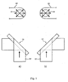
- Fig. 1
- eine schematische Darstellung der Wendestange in einer ersten a) und einer zweiten b) Stellung;
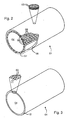
- Fig. 2
- einen perspektivischer, teilweise aufgebrochener Schnitt der Wendestange mit Träger und vollumfänglicher Beschichtung mit porösem Material;
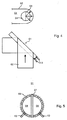
- Fig. 3
- einen perspektivischen Schnitt der Wendestange mit vollumfänglich angeordneten Mikrobohrungen;
- Fig. 4
- eine schematische Darstellung für eine verschwenkbare Wendestange in anderer Ausführung;
- Fig. 5
- einen Schnitt durch eine Wendestange nach
Fig. 4 .
- Fig. 1
- a schematic representation of the turning bar in a first a) and a second b) position;
- Fig. 2
- a perspective, partially broken section of the turning bar with carrier and full coating with porous material;
- Fig. 3
- a perspective section of the turning bar with fully arranged microbores;
- Fig. 4
- a schematic representation of a pivotable turning bar in another embodiment;
- Fig. 5
- a section through a turning bar after
Fig. 4 ,
Ein Leitelement 01, z. B. Bahnleitelement 01, dient in einer bahnerzeugenden oder - verarbeitenden Maschine, z. B. einer Papiermaschine, Wickelmaschine, Verpackungsmaschine oder insbesondere Druckmaschine, der Führung bzw. einem Richtungswechsel einer auf das Leitelement 01 auflaufenden Bahn 02, z. B. Materialbahn 02 oder Bedruckstoffbahn 02, insbesondere Papierbahn 02. Das Leitelement 01 ist insbesondere als sog. Wendestange 01 ausgeführt, mittels welcher- abhängig von ihrer Stellung relativ zur Richtung der ein- bzw. auflaufenden Bahn 02 -durch Umschlingung der Wendestange 01 für die Bahn 02 ein Richtungswechsel um ca. +90° oder ca.-90° bewirkt wird. Die Wendestange 01 kann als Paar von zwei parallelen, 45° zur Bahntransportrichtung geneigte Wendestangen 01 zum seitlichen Versatz, oder als Paar von unter 90° zueinander gekreuzten, um 45° bzw.-45° zur Bahntrnsportrichtung geneigten Wendestangen 01 zum Stürzen der Bahn 01 dienen. Vorteilhafterweise sind mehrere Wendestangenpaare angeordnet.A
Die Wendestange 01 bzw. das Wendestangenpaar, kann nach einem Druckwerk und vor einem Falzapparat oder nach einem Trockner und vor einem Falzapparat einer Rotationsdruckmaschine angeordnet sein. Sie weist z. B. einen Außendurchmesser von 60 - 100 mm und beispielsweise eine Länge von mehr als 1.200 mm auf. Dabei weist die Wendestange 01 (bzw. weisen beide Wendestangen 01 jeweils) mindestens zwei Stellungen auf und ist (bzw. sind) insbesondere um 90° schwenkbar, wobei in einer ersten Stellung eine erste Hälfte der Mantelfläche in Umfangsrichtung von einer Bahn 02 umschlungen wird (
Die Mantelfläche der Wendestange 01 weist Öffnungen 03, z. B. Mikroöffnungen 03 auf, durch welche im Betrieb aus einem im Innern liegenden Hohlraum 04, z. B. einer Kammer 04, insbesondere Druckkammer 04, unter Überdruck gegen die Umgebung stehendes Fluid, z. B. eine Flüssigkeit, ein Gas oder ein Gemisch, insbesondere Luft, strömt. In den Figuren ist eine entsprechende Zuleitung von Druckluft in den Hohlraum 04 nicht dargestellt.The lateral surface of the turning
Die Wendestange 01 weist auf ihre Mantelfläche in Umfangsrichtung sowohl auf der in der jeweiligen Betriebssituation umschlungenen Seite als auch auf der nicht durch die Bahn 02 bedeckten, d. h. der abgewandten Seite Mikroöffnungen 03 auf. Zumindest auf einem zur Umschlingung vorgesehenen Längsabschnitt der Wendestange 01 weist diese somit über den vollen Umfang von 360° (zugewandte als auch abgewandte Seite) verteilte Mikroöffnungen 03 auf. In bevorzugter Ausführung ist für die Wendestange 01 keinerlei Vorrichtung oder Mechanismus vorgesehen, welche(r) im Betrieb das Strömen des Fluids vom Hohlraum 04 durch die Mikroöffnungen 03 auf der der Bahn 02 abgewandeten Seite unterbindet. D. h., die Mikroöffnungen 03 sind in jeder der mindestens zwei genannten Betriebsituationen in einem vollständigen Umfangsbereich von 360° mit Fluid durchströmbar bzw. durchströmt. Ein Umstellen der Wendestange 01 von einer in die andere Stellung erfordert lediglich ein Verschwenken, und kein zusätzliches Abdecken der Öffnungen bzw. kein Unterbrechen des Durchtrittsweges zwischen Hohlraum 04 und Mikroöffnung 03.The turning
Diese einfache Ausführung wird durch die Ausbildung der Öffnungen 03 als Mikroöffnungen 03 sinnvoll möglich, da hiermit ein dünneres aber homogeneres Luftpolster geschaffen, gleichzeitig ein erforderlicher bzw. resultierender Volumenstrom und damit auch ein Verluststrom über die "offene" Seite erheblich reduziert ist. Der hohe Widerstand der Mikroöffnungen 03 bewirkt im Gegensatz zu Öffnungen großen Querschnitts, dass ein "Nichtbedecken" eines Bereichs von Öffnungen nicht zu einer Art Kurzschlussstrom führt. Im Gesamtwiderstand erhält der über die Öffnungen 03 abfallende Teilwiderstand ein erhöhtes Gewicht.This simple design is made possible by the formation of the
In einer ersten Ausführung sind die Mikroöffnungen 03 als offene Poren an der Oberfläche eines porösen, insbesondere mikroporösen, luftdurchlässigen Materials 06, z. B. aus einem offenporigen Sintermaterial 06, insbesondere aus Sintermetall, ausgebildet. Die Poren des luftdurchlässigen porösen Materials 06 weisen einen mittleren Durchmesser (mittlere Größe) von kleiner 150 µm, z. B. 5 bis 60 µm, insbesondere 10 bis 30 µm auf. Das Material 06 ist mit einer unregelmäßigen, amorphen Struktur ausgebildet.In a first embodiment, the micro-openings 03 as open pores on the surface of a porous, in particular microporous, air-
Materialwahl, Dimensionierung und Druckbeaufschlagung sind derart gewählt, dass aus der Luftaustrittsfläche des Sintermaterials 06 pro Stunde 1 - 20 Normkubikmeter pro m2, insbesondere 2 bis 15 Normkubikmeter pro m2, austreten. Besonders vorteilhaft ist der Luftaustritt von 3 bis 7 Normkubikmeter pro m2.Choice of material, dimensioning and pressurization are selected such that 1 to 20 standard cubic meters per m 2 , in particular 2 to 15 standard cubic meters per m 2 , emerge from the air outlet surface of the sintered material 06 per hour. Particularly advantageous is the air outlet of 3 to 7 standard cubic meters per m 2 .
Vorteilhaft wird die Sinterfläche aus dem Hohlraum 04 heraus mit einem Überdruck von mindestens 1 bar, insbesondere mit mehr als 4 bar, beaufschlagt. Besonders vorteilhaft ist eine Beaufschlagung der Sinterfläche mit einem Überdruck von 5 bis 7 bar.Advantageously, the sintered surface from the
Wird der Hohlraum 04 der Wendestange 01, zumindest auf ihrem mit der Bahn 01 zusammen wirkenden Längsabschnitt, im wesentlichen allein aus einem den Hohlraum 04 bildenden Körper aus porösem Vollmaterial gebildet (d. h. ohne weitere lasttragende Schichten), so ist dieser z. B. rohrförmig ausgebildete Körper im wesentlichen selbsttragend mit einer Wandstärke von größer oder gleich 2 mm, insbesondere größer oder gleich 3 mm, ausgebildet. Ggf. kann im Hohlraum 04 ein Träger verlaufen, auf welchem sich der Körper punktuell bzw. bereichsweise abstützen kann, welcher jedoch nicht vollflächig mit dem Körper im Wirkkontakt steht.If the
Um eine gleichmäßige Verteilung von an der Oberfläche des mikroporösen Materials 06 austretender Luft zu erzielen, ohne gleichzeitig hohe Schichtdicken des Materials 06 mit entsprechend erhöhtem Strömungswiderstand zu benötigen, ist es in einer vorteilhaften Ausführung zweckmäßig, dass die Wendestange 01 einen festen, zumindest bereichsweise luftdurchlässigen Träger 07 aufweist, auf dem das mikroporöse Material 06 als Schicht 06 aufgebracht ist (
Im dargestellten Ausführungsbeispiel nimmt das Trägermaterial im wesentlichen die Gewichts-, Scher-, Torsions-, Biege- und/oder Scherkräfte des Bauteils auf, weshalb eine entsprechende Wandstärke (z. B. größer als 3 mm, insbesondere größer 5 mm) des Trägers 07 und/oder eine entsprechend versteifte Konstruktion gewählt ist. Der z. B. den Hohlraum 04 zur Schicht 06 hin begrenzende, oder durch entsprechende Formgebung (z. B. rohrförmig) den Hohlraum 04 bildende Träger 07 weist auf der mit dem porösen Material beschichteten Seite eine Vielzahl von Öffnungen 09 zur Zufuhr der Druckluft in das poröse Material 06 auf. Auch in den Öffnungen 09 des Trägers 07 kann sich im Bereich der Wandungen z. T. poröses Material befinden.In the illustrated embodiment, the carrier material absorbs substantially the weight, shear, torsion, bending and / or shear forces of the component, which is why a corresponding wall thickness (eg greater than 3 mm, in particular greater than 5 mm) of the
Das poröse Material 06 außerhalb der Durchführung 08 weist eine Schichtdicke, die kleiner als 1 mm ist, auf. Besonders vorteilhaft ist eine Schichtdicke zwischen 0,05 mm und 0,3 mm. Ein Anteil an offener Fläche im Bereich der wirksamen Außenfläche des porösen Materials, hier mit Öffnungsgrad bezeichnet, liegt zwischen 3 % und 30 %, bevorzugt zwischen 10 % und 25 %. Um eine gleichmäßige Luftverteilung zu erzielen, ist es außerdem wünschenswert, dass die Dicke der Schicht wenigstens dem Abstand benachbarter Öffnungen 09 des Trägers 07 entspricht.The
Die aus dem Sintermaterial 06 austretende Druckluft tritt in beiden Stellungen der Wendestangen in Umfangsrichtung vollständig, d. h. im wesentlichen über 360°, aus.The emerging from the
Gemäß
Der ggf. ebenfalls als Trägerrohr 07 ausgestaltete Träger 07 kann seinerseits jedoch ebenfalls aus porösem Material, jedoch mit einer besseren Luftdurchlässigkeit - z. B. einer größere Porengröße - als der des mikroporösen Materials der Schicht 06 ausgeführt sein. In diesem Fall werden die Öffnungen 09 des Trägers 07 durch offene Poren im Bereich der Oberfläche, und die Durchführungen 08 durch die sich über die Porosität im Inneren zufällig ausgebildeten Kanäle gebildet. Der Träger 07 kann aber auch aus einem beliebigen, den Hohlraum 04 umschließenden, mit Durchführungen 08 versehenem Flachmaterial bzw. geformtem Material gebildet sein. Auch Kombinationen dieser Alternativen kommen in Betracht.The possibly also designed as a
Der Innenquerschnitt einer nicht dargestellten Zuleitung zur Zuführung der Druckluft zur Wendestange ist kleiner 100 mm2, vorzugsweise liegt er zwischen 10 und 60 mm2.The inner cross section of a feed line, not shown, for supplying the compressed air to the turning bar is less than 100 mm 2 , preferably between 10 and 60 mm 2 .
In einer zweiten Ausführung (
Eine u.a. den Strömungswiderstand beeinflussende Wandstärke der die Bohrungen beinhaltenden Kammerwand 12 liegt z. B. bei 0,2 bis 3,0 mm, vorteilhaft bei 0,2 bis 1,5 mm. insbesondere von 0,3 bis 0,8 mm. Im Innern der Wendestange 01, insbesondere im Hohlraum 04, kann eine nicht dargestellte verstärkende Konstruktion, beispielsweise ein sich in Längsrichtung der Wendestange 01 erstreckender Träger, insbesondere Metallträger, angeordnet sein, auf welchem sich die Kammerwand 12 zumindest abschnittsweise bzw. punktuell abstützt.One u.a. the flow resistance influencing wall thickness of the holes containing
Die die Kammer 04 umschließende Wand 12 ist z. B. durch einen Hohlprofilkörper, vorzugsweise einen rohrförmigen Hohlprofilkörper, insbesondere einen Hohlprofilkörper mit kreisringförmigen Profil ausgebildet.The
Für die Ausführung der Mikroöffnungen 03 als Öffnungen 03 von Bohrungen 11 ist z. B. ein Überdruck in der Kammer 04 von 0,5 bis 2 bar, insbesondere von 0,5 bis 1,0 bar von Vorteil.For the execution of the micro-openings 03 as
Die Bohrungen 11 können zylindrisch, trichterförmig oder aber mit anderer spezieller Formgebung (z. B. in Form einer Lavaldüse) ausgeführt sein.The holes 11 may be cylindrical, funnel-shaped or other special Shaping (eg in the form of a Laval nozzle) be executed.
Die Mikroperforation, d. h. die Herstellung der Bohrungen 11, erfolgt vorzugsweise durch Bohren mittels beschleunigter Teilchen (z. B. Flüssigkeit wie beispielsweise Wasserstrahl, Ionen oder Elementarteilchen) oder mittels elektromagnetischer Strahlung hoher Energiedichte (z. B. Licht mittels Laserstrahl). Insbesondere vorteilhaft ist die Herstellung mittels Elektronenstrahl.The microperforation, d. H. the bores 11 are preferably produced by drilling by means of accelerated particles (eg liquid such as water jet, ions or elementary particles) or by means of electromagnetic radiation of high energy density (eg light by means of a laser beam). Particularly advantageous is the production by means of electron beam.
Die der Bahn 02 zugewandte Seite der die Bohrungen 11 aufweisenden Wand 12, z. B. eine aus Edelstahl gebildete Wand 12, weist in bevorzugter Ausführung eine schmutz- und/oder farbabweisende Veredelung auf. Sie weist eine nicht dargestellte, die Öffnungen 03 bzw. Bohrungen 11 nicht bedeckende Beschichtung - z. B. Nickel oder vorteilhaft Chrom - auf, welche z. B. zusätzlich bearbeitet ist - z. B. mit Mikrorippen oder einen Lotusblüteneffekt bewirkend strukturiert oder aber vorzugsweise hochglanzpoliert).The
Die die Bohrungen aufweisende Wand ist in einer Variante als ein Einsatz oder mehrere Einsätze in einem Träger ausgebildet. Der Einsatz kann fest oder wechselbar mit dem Träger verbunden sein. Letzteres ist von Vorteil bzgl. einer Reinigung oder aber eines Austauschs von Einsätzen verschiedenartiger Mikroperforationen zur Anpassung an unterschiedliche Materialien und Bahnbreiten. In der Ausführung mit im wesentlichen vollumfänglich angeordneten Öffnungen 03, können derartige Einsätze beispielsweise auf einem im Hohlraum 04 verlaufenden Träger angeordnet sein.The holes having the wall is formed in a variant as one or more inserts in a carrier. The insert may be fixed or changeable connected to the carrier. The latter is advantageous with respect to a cleaning or an exchange of inserts of different types of microperforations for adaptation to different materials and web widths. In the embodiment with substantially fully arranged
Bei einem weiteren Beispiel (
- 0101
- Leitelement, Bahnleitelement, WendestangeGuide element, web guide element, turning bar
- 0202
- Bahn, Materialbahn, Bedruckstoffbahn, PapierbahnWeb, material web, substrate web, paper web
- 0303
- Öffnung, MikroöffnungOpening, micro opening
- 0404
- Hohlraum, Kammer, DruckkammerCavity, chamber, pressure chamber
- 0505
- --
- 0606
- mikroporöses Material, Sintermaterial, Schicht, mikroporös, Beschichtungmicroporous material, sintered material, layer, microporous, coating
- 0707
- Träger, Innenkörper, TrägerrohrCarrier, inner body, support tube
- 0808
- Durchführung, DurchgangsöffnungFeedthrough, passage opening
- 0909
- Öffnungopening
- 1010
- --
- 1111
- Bohrung, MikrobohrungBore, micro bore
- 1212
- Wand, KammerwandWall, chamber wall
- 1313
- Zuleitungsupply
Claims (30)
- A guide element of a web-producing or -processing machine with a plurality of openings (03), arranged in its generated surface at least in a longitudinal section of the guide element (01) substantially around the entire periphery, for a pressurised fluid to emerge, the guide element (01) being able to be placed in at least two angular positions with respect to an incoming web (02), characterised in that the openings (03) are in the form of micro-openings (03) with a diameter of less than 500 µm, that the micro-openings (03) are in the form of open pores of a porous material (06) through which the fluid flows, which material is formed as a layer (06) on a load-bearing support (07) which is however, at least in regions, permeable to fluid, and in that in both angular positions the fluid in this longitudinal section emerges from the micro-openings substantially over the entire periphery.
- A guide element of a web-producing or -processing machine with a plurality of openings (03) for a pressurised fluid to emerge, the guide element (01) being able to be placed in at least two angular positions with respect to an incoming web (02), characterised in that in each of the two angular positions, both on a side facing the web (02) and around which the web (02) wraps and on an opposite side of the guide element (01) which faces away therefrom, the fluid emerges from openings (03) provided therein, in that the openings (03) are in the form of outward-directed openings (03) of microbores (11) having a diameter of less than 500 µm in a wall (12) which delimits the guide element (01) on the outside.
- A guide element according to Claim 2, characterised in that the openings (03) in the generated surface of the guide element (01), at least in a longitudinal section of the guide element (01), are arranged substantially around the entire periphery.
- A guide element according to Claim 1 or 2, characterised in that in both angular positions the fluid in a longitudinal section emerges from the openings (03) substantially over the entire periphery.
- A guide element according to Claim 1 or 2, characterised in that the guide element (01) is pivotable by 90°, with in a first angular position a first, substantially half-shell-like half of the cylindrical generated surface, and in a second angular position a second half-shell-like half of the generated surface, being wrapped by the web (02).
- A guide element according to Claim 1, characterised in that the pores of the fluid-permeable porous material have an average diameter of 5 to 50 µm, in particular 10 - 30 µm.
- A guide element according to Claim 1, characterised in that the porous material (06) is in the form of an open-pored sintered material (06), in particular a sintered metal.
- A guide element according to Claim 1, characterised in that the support (07) has on its side facing the layer (06) at least one supporting surface connected to the layer (06) and also a plurality of openings (09) for supplying the fluid to the layer (06).
- A guide element according to Claim 1, characterised in that the layer (06) has in the region of the supporting surface a thickness of less than 1 mm, in particular of 0.05 mm to 0.3 mm.
- A guide element according to Claim 1, characterised in that the support (07) has on its width and length which cooperate with the layer (06) in each case a plurality of, in particular non-coherent, through-passages.
- A guide element according to Claim 1, characterised in that the support (07) is in the form of a support tube (07) with a hollow profile, in particular a profile in the shape of a circular ring.
- A guide element according to Claim 11, characterised in that a wall thickness of the support tube (07) is greater than 3 mm, in particular greater than 5 mm.
- A guide element according to Claim 1, characterised in that a degree of opening on the outward-pointing surface of the porous material (06) is between 3% and 30%, preferably between 10% and 25%.
- A guide element according to Claim 2, characterised in that a diameter of the openings (03) is less than or equal to 300 µm, in particular between 60 and 150 µm.
- A guide element according to Claim 2, characterised in that a wall thickness of the wall (12) is 0.2 to 3.0 mm.
- A guide element according to Claim 2, characterised in that a hole density, i.e. a number of openings (03) per unit of surface area, for the surface provided with the micro-openings (03) is at least 0.2 / mm2.
- A guide element according to Claim 1 or 2, characterised in that 1 - 20 standard cubic metres of air per hour emerge from one square meter of the generated surface having the openings (03).
- A guide element according to Claim 1 or 2, characterised in that 2 - 15, in particular 3 - 7, standard cubic metres of air per hour emerge on one square meter of the generated surface having the openings (03).
- A guide element according to Claim 1, characterised in that the porous material (06) is acted upon from the inside with at least 1 bar excess pressure.
- A guide element according to Claim 1, characterised in that the porous material (06) is acted upon by the fluid from the inside with more than 4 bar, in particular with 5 to 7 bar, excess pressure.
- A guide element according to Claim 1 or 2, characterised in that a feed line for supplying the fluid to the guide element (01) has an internal cross-section of less than 100 mm2, in particular between 10 and 60 mm2.
- A guide element according to Claim 1 or 2, characterised in that the external diameter of the guide element (01) is 60 - 100 mm.
- A guide element according to Claim 1 or 2, characterised in that the guide element (01) has a length of greater than 1,200 mm.
- A guide element according to Claim 1 or 2, characterised in that the guide element (01) is in the form of a turning bar (01).
- A guide element according to Claim 1 or 2, characterised in that the pressurised fluid is in the form of compressed air.
- A guide element according to Claim 2, characterised in that the bores (11) are produced by means of accelerated particles.
- A guide element according to Claim 26, characterised in that the bores (11) are produced by drilling by means of an electron beam.
- A guide element according to Claim 2, characterised in that at least one wall section of the guide element (01) which has the bores (11) has on its surface a dirt-repellent and/or ink-repellent finish.
- A guide element according to Claim 28, characterised in that the finish is in the form of a coating by chromium.
- A guide element according to Claim 29, characterised in that the surface is produced with a high-polish finish.
Priority Applications (1)
| Application Number | Priority Date | Filing Date | Title |
|---|---|---|---|
| EP08161186A EP1997759B1 (en) | 2002-10-19 | 2003-10-20 | Guiding element for a strip-producing or strip-processing machine |
Applications Claiming Priority (9)
| Application Number | Priority Date | Filing Date | Title |
|---|---|---|---|
| DE10248820 | 2002-10-19 | ||
| DE10248820 | 2002-10-19 | ||
| DE10307089A DE10307089B4 (en) | 2002-10-19 | 2003-02-19 | Squeegee of a printing press |
| DE10307089 | 2003-02-19 | ||
| DE10322651 | 2003-05-20 | ||
| DE10322651 | 2003-05-20 | ||
| DE10331469 | 2003-07-11 | ||
| DE10331469 | 2003-07-11 | ||
| PCT/DE2003/003474 WO2004037696A2 (en) | 2002-10-19 | 2003-10-20 | Guiding elements for a strip-producing or strip-processing machine |
Related Child Applications (1)
| Application Number | Title | Priority Date | Filing Date |
|---|---|---|---|
| EP08161186A Division EP1997759B1 (en) | 2002-10-19 | 2003-10-20 | Guiding element for a strip-producing or strip-processing machine |
Publications (2)
| Publication Number | Publication Date |
|---|---|
| EP1556300A2 EP1556300A2 (en) | 2005-07-27 |
| EP1556300B1 true EP1556300B1 (en) | 2008-11-05 |
Family
ID=32180556
Family Applications (8)
| Application Number | Title | Priority Date | Filing Date |
|---|---|---|---|
| EP03776804A Expired - Lifetime EP1554208B1 (en) | 2002-10-19 | 2003-10-20 | Former for a strip-producing or strip-processing machine |
| EP03776803A Expired - Lifetime EP1554207B1 (en) | 2002-10-19 | 2003-10-20 | Folder |
| EP03776806A Expired - Lifetime EP1556219B1 (en) | 2002-10-19 | 2003-10-20 | Guiding elements for a printing unit |
| EP03778236A Expired - Lifetime EP1556218B1 (en) | 2002-10-19 | 2003-10-20 | Doctor blade devices for a strip-producing or strip-processing machine |
| EP03776807A Expired - Lifetime EP1556300B1 (en) | 2002-10-19 | 2003-10-20 | Guiding elements for a strip-producing or strip-processing machine |
| EP06100923A Expired - Lifetime EP1655257B1 (en) | 2002-10-19 | 2003-10-20 | Folder |
| EP03776805A Expired - Lifetime EP1554122B1 (en) | 2002-10-19 | 2003-10-20 | Pressure elements for a strip-processing printing machine |
| EP08161186A Expired - Lifetime EP1997759B1 (en) | 2002-10-19 | 2003-10-20 | Guiding element for a strip-producing or strip-processing machine |
Family Applications Before (4)
| Application Number | Title | Priority Date | Filing Date |
|---|---|---|---|
| EP03776804A Expired - Lifetime EP1554208B1 (en) | 2002-10-19 | 2003-10-20 | Former for a strip-producing or strip-processing machine |
| EP03776803A Expired - Lifetime EP1554207B1 (en) | 2002-10-19 | 2003-10-20 | Folder |
| EP03776806A Expired - Lifetime EP1556219B1 (en) | 2002-10-19 | 2003-10-20 | Guiding elements for a printing unit |
| EP03778236A Expired - Lifetime EP1556218B1 (en) | 2002-10-19 | 2003-10-20 | Doctor blade devices for a strip-producing or strip-processing machine |
Family Applications After (3)
| Application Number | Title | Priority Date | Filing Date |
|---|---|---|---|
| EP06100923A Expired - Lifetime EP1655257B1 (en) | 2002-10-19 | 2003-10-20 | Folder |
| EP03776805A Expired - Lifetime EP1554122B1 (en) | 2002-10-19 | 2003-10-20 | Pressure elements for a strip-processing printing machine |
| EP08161186A Expired - Lifetime EP1997759B1 (en) | 2002-10-19 | 2003-10-20 | Guiding element for a strip-producing or strip-processing machine |
Country Status (9)
| Country | Link |
|---|---|
| US (3) | US7383772B2 (en) |
| EP (8) | EP1554208B1 (en) |
| JP (1) | JP2006502937A (en) |
| CN (2) | CN1319832C (en) |
| AT (8) | ATE337255T1 (en) |
| AU (6) | AU2003286098A1 (en) |
| DE (8) | DE50304781D1 (en) |
| ES (2) | ES2289732T3 (en) |
| WO (6) | WO2004037696A2 (en) |
Families Citing this family (34)
| Publication number | Priority date | Publication date | Assignee | Title |
|---|---|---|---|---|
| DE10339262A1 (en) * | 2003-08-26 | 2005-03-17 | Voith Paper Patent Gmbh | Web guiding means |
| US7921771B2 (en) * | 2004-06-23 | 2011-04-12 | Koenig & Bauer Aktiengesellschaft | Web-fed printing machine having a turning bar |
| US7311234B2 (en) * | 2005-06-06 | 2007-12-25 | The Procter & Gamble Company | Vectored air web handling apparatus |
| DE102006013956B4 (en) | 2006-03-27 | 2008-02-07 | Koenig & Bauer Aktiengesellschaft | Printing machine with a device for feeding a material web and a method for feeding a material web |
| DE102006013955B3 (en) | 2006-03-27 | 2007-10-31 | Koenig & Bauer Aktiengesellschaft | Means for feeding a web of material to a printing unit |
| DE102006013954B4 (en) * | 2006-03-27 | 2008-03-06 | Koenig & Bauer Aktiengesellschaft | Printing machine with a device for feeding a material web |
| WO2008142069A1 (en) * | 2007-05-21 | 2008-11-27 | Koenig & Bauer Aktiengesellschaft | Method and device for producing a product section in a web processing machine, and product section |
| DE102007000507B4 (en) | 2007-10-15 | 2010-03-11 | Koenig & Bauer Aktiengesellschaft | Roller of a dryer |
| DE102007000508B4 (en) | 2007-10-15 | 2011-09-15 | Koenig & Bauer Aktiengesellschaft | Dryer for at least one material web |
| DE102008041424A1 (en) * | 2008-08-21 | 2010-02-25 | Voith Patent Gmbh | Device for processing running material web, has feeder device for feeding material web, and delivery device for conducting material web |
| TWI349644B (en) * | 2008-09-18 | 2011-10-01 | Ind Tech Res Inst | Suction roller and transporting apparatus using the same |
| TWI367855B (en) * | 2008-09-24 | 2012-07-11 | Apparatus and method for guiding the web position | |
| EP2337687B1 (en) * | 2008-10-10 | 2014-03-05 | Hewlett-Packard Development Company, L.P. | Automatic cleaning air idler |
| DE102009002103B4 (en) | 2009-04-01 | 2011-07-07 | KOENIG & BAUER Aktiengesellschaft, 97080 | Printing machine and a method for printing a web-shaped substrate |
| DE102009026059B4 (en) * | 2009-06-29 | 2024-02-01 | Krones Aktiengesellschaft | Device for spreading a film web |
| DE202010005837U1 (en) | 2010-04-16 | 2010-07-29 | Prospective Concepts Ag | Guide element of a web-forming or -processing machine |
| EP2502725B1 (en) * | 2011-03-24 | 2015-01-07 | PackSys Global (Switzerland) Ltd. | Device and method for manufacturing tubular bodies |
| DE102011106695A1 (en) * | 2011-07-06 | 2013-01-10 | Multivac Sepp Haggenmüller Gmbh & Co. Kg | Method and device for heating a film |
| EP2748005B1 (en) * | 2011-08-22 | 2015-10-14 | Windmöller & Hölscher KG | Machine and method for printing webs of material |
| DE102011117494A1 (en) * | 2011-10-31 | 2013-05-02 | Eastman Kodak Company | Apparatus and method for printing a substrate web |
| US20130256362A1 (en) * | 2012-03-30 | 2013-10-03 | Michael T. Dobbertin | Replaceable cover for bars in a printing system |
| CN103434887B (en) * | 2013-08-30 | 2015-09-02 | 无锡宝南机器制造有限公司 | Set square moves regulating mechanism |
| CN103569776A (en) * | 2013-11-06 | 2014-02-12 | 北京印刷学院 | Fold triangular plate device |
| CN104609246A (en) * | 2015-01-16 | 2015-05-13 | 常州市永明机械制造有限公司 | Folded cloth cover expansion device of laminating machine |
| CN105035839A (en) * | 2015-06-15 | 2015-11-11 | 青岛正大环保科技有限公司 | Multi-stage film half-folding device |
| GB2560194B (en) * | 2017-03-03 | 2021-03-31 | Kingspan Holdings Irl Ltd | Process and apparatus for producing shaped profile sections |
| CN107095740A (en) * | 2017-03-21 | 2017-08-29 | 泉州市汉威机械制造有限公司 | A kind of disposable product fold mechanism |
| JP6527981B1 (en) * | 2018-03-27 | 2019-06-12 | 株式会社タンケンシールセーコウ | Turn bar |
| CN113631524B (en) * | 2018-12-13 | 2023-04-11 | 康宁公司 | Conveying apparatus and conveying belt |
| TW202100832A (en) * | 2019-03-11 | 2021-01-01 | 以色列商核心流有限公司 | Fluid flow web tension device for roll-to-roll processing |
| IT201900003553A1 (en) * | 2019-03-12 | 2020-09-12 | Gtk Timek Group Sa | "HANDLING BAR FOR LAMINATED OR FILM SUPPORTS" |
| CN111016408A (en) * | 2019-12-31 | 2020-04-17 | 江苏斯派尔建材科技有限公司 | Novel metal wood grain keeps warm and decorates intergral template stamp system |
| DE102021103766A1 (en) | 2021-02-17 | 2022-08-18 | Manroland Goss Web Systems Gmbh | Funnel nose and fold former |
| US20230129901A1 (en) * | 2021-10-21 | 2023-04-27 | Gerhard Designing & Manufacturing Inc. | Excess coating removal device for can coating machines |
Family Cites Families (91)
| Publication number | Priority date | Publication date | Assignee | Title |
|---|---|---|---|---|
| GB794404A (en) * | 1956-09-01 | 1958-05-07 | Richard Kurt Sinejda | Multi-colour attachment to the print roller in roller printing |
| US3097971A (en) * | 1960-11-09 | 1963-07-16 | British Iron Steel Research | Method of and apparatus for supporting or guiding strip material |
| DE1142878B (en) | 1961-01-28 | 1963-01-31 | Maschf Augsburg Nuernberg Ag | Fold former for longitudinal folding of paper webs processed in rotary printing machines |
| US3111310A (en) * | 1961-12-21 | 1963-11-19 | Orville V Dutro | Folder |
| US3245334A (en) | 1962-08-27 | 1966-04-12 | Du Pont | Noncontacting sealing method and apparatus |
| US3518940A (en) | 1967-06-30 | 1970-07-07 | Cameron Machine Co | Endless belt printing machine |
| DE1954316A1 (en) * | 1969-10-29 | 1971-05-19 | Schluckebier Wilhelm | Method and device for charging rollers in printing units of printing machines with a liquid medium, e.g. Color, and for dosing the medium |
| DE2026355B1 (en) | 1970-05-29 | 1971-11-18 | Roland Offsetmaschinenfabrik Faber & Schleicher Ag, 6050 Offenbach | Turning bar for diverting paper webs |
| DE2142902A1 (en) * | 1971-08-27 | 1973-03-08 | Dornier Ag | DEVICE FOR CUTTING, COLLECTING AND FOLDING ONE OR MORE INCOMING PAPER TRAILS |
| DE2215523A1 (en) | 1972-03-30 | 1973-10-04 | Anger Kunststoff | Plastic extrusion calibration - with steel/graphite bush in aluminium/plastic housing with spiral cooling channel |
| DE2215532B2 (en) | 1972-03-30 | 1976-01-02 | Saueressig Gmbh, 4422 Ahaus | Roller printing machine for multi-colored printing of webs |
| US4035878A (en) * | 1974-11-06 | 1977-07-19 | Sw (Delaware), Inc. | Apparatus for smoothing the surfaces of moving webs |
| US4221596A (en) * | 1976-10-04 | 1980-09-09 | General Motors Corporation | Method for low pressure forming of fused silica compositions and resultant bodies |
| US4176775A (en) * | 1977-03-28 | 1979-12-04 | Beloit Corporation | Inhibiting noise in sheet spreaders |
| FR2456695A1 (en) * | 1979-02-13 | 1980-12-12 | Pliage Service | Folding and gluing machine for advertising leaflets - folds paper into square with internal edges glued |
| DE2921757A1 (en) * | 1979-05-29 | 1980-12-04 | Maschf Augsburg Nuernberg Ag | METHOD FOR PRODUCING A FUNNEL SHEET FOR A FOLDING HOPPER OF A ROTARY PRINTING MACHINE, AND A FUNNEL SHEET PRODUCED THEREFORE |
| DE2931968B1 (en) * | 1979-08-07 | 1981-07-16 | Heidelberger Druckmaschinen Ag, 6900 Heidelberg | Folder on web-fed rotary printing machines |
| DD152754A1 (en) | 1980-08-29 | 1981-12-09 | Dietrich Hank | AIR-FLUSHED WENDESTANGE, IN PARTICULAR FOR THE CHANGING OF DIRECTIONS OF RUNNING MATERIALS |
| US4361089A (en) * | 1980-10-20 | 1982-11-30 | Magna-Graphics Corporation | Multi-color rotary press |
| JPS57167330A (en) | 1981-04-09 | 1982-10-15 | Asahi Chem Ind Co Ltd | Material for sintered body |
| DE3127872C2 (en) * | 1981-07-15 | 1985-11-28 | M.A.N.- Roland Druckmaschinen AG, 6050 Offenbach | Turning bar trolley |
| US4416201A (en) * | 1981-11-18 | 1983-11-22 | Monarch Marking Systems, Inc. | Ink roller assembly with capillary ink supply |
| DE3212826A1 (en) | 1982-04-06 | 1983-10-13 | Deilmann-Haniel GmbH, 4600 Dortmund | Brake arrangement for conveying machines, reels and winches |
| DE3225360A1 (en) | 1982-07-07 | 1984-02-09 | M.A.N.- Roland Druckmaschinen AG, 6050 Offenbach | ROLL OFFSET ROTATION PRINTING MACHINE |
| JPS59192571A (en) | 1983-04-18 | 1984-10-31 | Toray Ind Inc | Doctor for printing by intaglio printing plate |
| JPS6112396A (en) | 1984-06-29 | 1986-01-20 | Toray Ind Inc | Doctor blade |
| US4701233A (en) * | 1986-01-16 | 1987-10-20 | Pitney Bowes Inc. | Method for folding and sealing sheets |
| FR2598962B1 (en) * | 1986-05-21 | 1988-12-23 | Prepac Sarl | FLEXIBLE FILM CONFORMER WITH SURFACE MOUTHPIECES |
| EP0306684B1 (en) * | 1987-09-11 | 1992-04-08 | M.A.N.-ROLAND Druckmaschinen Aktiengesellschaft | Device for pressing a sheet against the impression cylinder in a rotary sheet-fed printing press for multicolour printing |
| US5031528A (en) | 1988-04-16 | 1991-07-16 | Elmar Messerschmitt | Doctor for screen printing |
| US4957045A (en) * | 1988-04-16 | 1990-09-18 | Elmar Messerschmitt | Doctor for screen printing |
| US4865578A (en) * | 1988-05-16 | 1989-09-12 | Moll Richard J | Glue head mounting bracket for glue applying folding machines |
| US4925080A (en) * | 1988-10-13 | 1990-05-15 | Beloit Corporation | Spreader bar apparatus |
| DE3939501A1 (en) * | 1989-11-30 | 1991-06-06 | Convac Gmbh | Laminar coating jig for substrate - has slit tube lacquer dispenser for underside of horizontal substrate |
| US5082533A (en) * | 1990-04-10 | 1992-01-21 | Beloit Corporation | Heated extended nip press with porous roll layers |
| WO1991017943A1 (en) * | 1990-05-11 | 1991-11-28 | Liedtke Rudolph J | Air bearing for web material |
| DE4127602A1 (en) * | 1991-08-21 | 1993-02-25 | Hoechst Ag | METHOD AND DEVICE FOR THE CONTACT-FREE LEADING OF A COATED MATERIAL TAPE |
| US5850788A (en) | 1992-01-14 | 1998-12-22 | Maschinenfabrik Wifag | Metering strip |
| DE4200769C1 (en) | 1992-01-14 | 1993-07-22 | Maschinenfabrik Wifag, Bern, Ch | |
| FI87669C (en) * | 1992-03-02 | 1993-02-10 | Valmet Paper Machinery Inc | FOERFARANDE OCH TORK VID TORKNING AV PAPPER |
| JPH0639991A (en) | 1992-07-22 | 1994-02-15 | Mitsubishi Heavy Ind Ltd | Scratching off blade |
| US5316199A (en) | 1992-09-18 | 1994-05-31 | Rockwell International Corporation | Adjustable angle bar assembly for a printing press |
| DE4234307A1 (en) * | 1992-10-12 | 1994-04-14 | Heidelberger Druckmasch Ag | Device for trouble-free product conveyance in folders |
| JP3111721B2 (en) | 1993-01-07 | 2000-11-27 | 東洋インキ製造株式会社 | Progressive web conversion method |
| US5505042A (en) * | 1993-03-29 | 1996-04-09 | Liberty Industries | Air assisted feed through conveyor for rotary film wrapping apparatus |
| DE9320281U1 (en) | 1993-04-07 | 1994-03-17 | Koenig & Bauer Ag | Turning bar for a material web |
| DE4311438C2 (en) * | 1993-04-07 | 1997-06-19 | Koenig & Bauer Albert Ag | Turning bar for a material web |
| JP2801519B2 (en) * | 1993-04-08 | 1998-09-21 | ゴス グラフイック システムズ インコーポレイテッド | Adjustable angle bar assembly for printing press |
| DE9311113U1 (en) | 1993-07-26 | 1993-09-09 | Zirkon Druckmaschinen Gmbh | Impression unit for flying changing impressions |
| JP3060791B2 (en) | 1993-08-10 | 2000-07-10 | 東洋インキ製造株式会社 | Progressive web conversion method |
| DE4330681A1 (en) | 1993-09-10 | 1995-03-16 | Roland Man Druckmasch | Chamber doctor |
| DE4335473C2 (en) * | 1993-10-18 | 2001-07-12 | Oce Printing Systems Gmbh | Turning device for a tape-shaped recording medium |
| DE4410189A1 (en) * | 1994-03-24 | 1995-09-28 | Heidelberger Druckmasch Ag | Guide device for moving sheet material in printing machines |
| DE4435528C2 (en) | 1994-10-05 | 1997-09-04 | Roland Man Druckmasch | Folder for a printing press |
| EP0705785A3 (en) | 1994-10-07 | 1996-11-13 | Eastman Kodak Co | Method and apparatus for preventing creases in thin webs |
| DE4446546A1 (en) | 1994-12-24 | 1996-06-27 | Philips Patentverwaltung | Vacuum maintaining device for green ceramic film in electronic module mfr. |
| US5807228A (en) * | 1995-01-13 | 1998-09-15 | F. L. Smithe Machine Company, Inc. | Sheet folding method and apparatus |
| DE29501537U1 (en) | 1995-02-01 | 1995-03-09 | Heidelberger Druckmasch Ag | Sheet guiding device with air supply boxes |
| DE19527761C2 (en) | 1995-07-28 | 2003-02-27 | Roland Man Druckmasch | Printing roller for attaching a printing sleeve |
| US5957360A (en) * | 1998-01-16 | 1999-09-28 | International Business Machines Corporation | System and method for transporting and clamping flexible film structures |
| US6004432A (en) | 1998-01-28 | 1999-12-21 | Beloit Technologies, Inc. | Sheet turn with vectored air supply |
| DE19803809A1 (en) * | 1998-01-31 | 1999-08-05 | Roland Man Druckmasch | Offset printing unit |
| FR2775474B1 (en) | 1998-02-27 | 2000-05-19 | Heidelberger Druckmasch Ag | PAPER STRIP GUIDE ROLL |
| US5947411A (en) * | 1998-03-26 | 1999-09-07 | Heidelberger Druckmaschinen Ag | Method and apparatus for air flotation |
| US5947026A (en) * | 1998-05-01 | 1999-09-07 | Heidelberger Druckmaschinen Ag | Apparatus for reducing downstream marking including folder marking |
| DE19829094C2 (en) * | 1998-06-30 | 2002-10-24 | Roland Man Druckmasch | Guide device for sheet-shaped substrates in a printing machine |
| DE19829095C2 (en) * | 1998-06-30 | 2002-04-25 | Roland Man Druckmasch | Sheet guiding device in a printing press |
| DE19850968A1 (en) | 1998-11-05 | 2000-05-25 | Roland Man Druckmasch | Wear-resistant, ink-repellent coating, especially of press components |
| DE19854053C2 (en) | 1998-11-24 | 2002-11-21 | Roland Man Druckmasch | Sheet guiding device for a printing machine |
| DE19902936A1 (en) | 1998-12-23 | 2000-06-29 | Bachofen & Meier Ag Buelach | Device for contactless guiding or treatment of a running material web, in particular a paper or cardboard web, metal or plastic film |
| ATE238218T1 (en) * | 1998-12-23 | 2003-05-15 | Bachofen & Meier Ag Maschf | DEVICE FOR THE NON-CONTACT GUIDING OR TREATING OF A RUNNING MATERIAL WEB, IN PARTICULAR PAPER OR CARDBOARD WEB, METAL OR PLASTIC FILM |
| DE29914420U1 (en) * | 1999-02-03 | 1999-10-14 | Planatol Klebetechnik Gmbh | Device for applying longitudinal sizing in a folding device of high-speed rotary printing machines |
| DE19911965C2 (en) | 1999-03-17 | 2003-04-30 | Wifag Maschf | Printing form, process for its production and printing forme cylinder for a wet offset printing |
| DE10044070A1 (en) * | 1999-10-01 | 2001-04-26 | Heidelberger Druckmasch Ag | Device for selectively closing blowing openings in guide devices or bars of printing presses carrying printing material |
| US6722608B1 (en) | 1999-10-28 | 2004-04-20 | Segway Systems, Llc | Porous air bearings for tape transports and method of fabrication thereof |
| US6402047B1 (en) * | 1999-10-29 | 2002-06-11 | Kevin S. Thomas | Snow making apparatus and method |
| US6364247B1 (en) * | 2000-01-31 | 2002-04-02 | David T. Polkinghorne | Pneumatic flotation device for continuous web processing and method of making the pneumatic flotation device |
| AT409301B (en) * | 2000-05-05 | 2002-07-25 | Ebner Peter Dipl Ing | DEVICE FOR GUIDING A METAL STRIP ON A GAS PILLOW |
| DE20008665U1 (en) | 2000-05-13 | 2000-08-24 | Aradex Gmbh | Printing press |
| DE10031814A1 (en) * | 2000-06-30 | 2002-01-10 | Heidelberger Druckmasch Ag | Device for contact-free guiding of material web over surface has facility whereby volume of gaseous medium flowing beneath web from air cushion is variable by means of adjustable closing element regardless of web format |
| DE10112416C1 (en) | 2001-03-15 | 2002-10-02 | Koenig & Bauer Ag | turning bar |
| DE10112415A1 (en) | 2001-03-15 | 2002-10-02 | Koenig & Bauer Ag | turning bar |
| DE10115918B4 (en) | 2001-03-30 | 2006-03-23 | Koenig & Bauer Ag | Turning bar for a material web |
| DE10115916B4 (en) | 2001-03-30 | 2006-03-23 | Koenig & Bauer Ag | Turning bar for a material web |
| US6673003B2 (en) * | 2001-05-09 | 2004-01-06 | The Procter & Gamble Company | Vacuum cleaning folding rail |
| US6705220B2 (en) * | 2001-06-22 | 2004-03-16 | Heidelberger Druckmaschinen Ag | Device for guiding a travelling web |
| DE10225200B4 (en) | 2002-06-06 | 2007-04-26 | Maschinenfabrik Wifag | Rotary body for compensation of fanout |
| US6796524B2 (en) | 2002-11-14 | 2004-09-28 | Heidelberger Druckmaschinen Ag | Reversible angle bar for a web printing press |
| DE20303720U1 (en) * | 2003-02-07 | 2003-05-15 | Roland Man Druckmasch | Rotary print machine web guided between rollers by compressed air shoes |
| DE20309429U1 (en) | 2003-06-17 | 2003-09-18 | Reifenhaeuser Masch | Extraction device of a tubular film extrusion system |
| US7311234B2 (en) | 2005-06-06 | 2007-12-25 | The Procter & Gamble Company | Vectored air web handling apparatus |
-
2003
- 2003-10-20 EP EP03776804A patent/EP1554208B1/en not_active Expired - Lifetime
- 2003-10-20 JP JP2005501504A patent/JP2006502937A/en active Pending
- 2003-10-20 WO PCT/DE2003/003474 patent/WO2004037696A2/en active Search and Examination
- 2003-10-20 WO PCT/DE2003/003469 patent/WO2004037697A2/en active Search and Examination
- 2003-10-20 EP EP03776803A patent/EP1554207B1/en not_active Expired - Lifetime
- 2003-10-20 DE DE50304781T patent/DE50304781D1/en not_active Expired - Fee Related
- 2003-10-20 AT AT03776804T patent/ATE337255T1/en not_active IP Right Cessation
- 2003-10-20 DE DE50310757T patent/DE50310757D1/en not_active Expired - Lifetime
- 2003-10-20 DE DE20380219U patent/DE20380219U1/en not_active Expired - Lifetime
- 2003-10-20 DE DE50304780T patent/DE50304780D1/en not_active Expired - Fee Related
- 2003-10-20 AU AU2003286098A patent/AU2003286098A1/en not_active Abandoned
- 2003-10-20 ES ES06100923T patent/ES2289732T3/en not_active Expired - Lifetime
- 2003-10-20 WO PCT/DE2003/003470 patent/WO2004037698A1/en active Search and Examination
- 2003-10-20 WO PCT/DE2003/003472 patent/WO2004037538A1/en active Search and Examination
- 2003-10-20 EP EP03776806A patent/EP1556219B1/en not_active Expired - Lifetime
- 2003-10-20 AU AU2003286102A patent/AU2003286102A1/en not_active Abandoned
- 2003-10-20 AU AU2003286099A patent/AU2003286099A1/en not_active Abandoned
- 2003-10-20 DE DE50309490T patent/DE50309490D1/en not_active Expired - Lifetime
- 2003-10-20 AT AT03776805T patent/ATE339311T1/en not_active IP Right Cessation
- 2003-10-20 DE DE50305063T patent/DE50305063D1/en not_active Expired - Lifetime
- 2003-10-20 US US10/531,211 patent/US7383772B2/en not_active Expired - Fee Related
- 2003-10-20 CN CNB2003801017211A patent/CN1319832C/en not_active Expired - Fee Related
- 2003-10-20 US US10/531,670 patent/US7314440B2/en not_active Expired - Fee Related
- 2003-10-20 EP EP03778236A patent/EP1556218B1/en not_active Expired - Lifetime
- 2003-10-20 AT AT06100923T patent/ATE367349T1/en not_active IP Right Cessation
- 2003-10-20 AU AU2003285264A patent/AU2003285264A1/en not_active Abandoned
- 2003-10-20 AT AT03776803T patent/ATE337253T1/en not_active IP Right Cessation
- 2003-10-20 EP EP03776807A patent/EP1556300B1/en not_active Expired - Lifetime
- 2003-10-20 AT AT08161186T patent/ATE435180T1/en not_active IP Right Cessation
- 2003-10-20 EP EP06100923A patent/EP1655257B1/en not_active Expired - Lifetime
- 2003-10-20 AT AT03776807T patent/ATE413354T1/en not_active IP Right Cessation
- 2003-10-20 CN CNB2003801017207A patent/CN100551798C/en not_active Expired - Fee Related
- 2003-10-20 EP EP03776805A patent/EP1554122B1/en not_active Expired - Lifetime
- 2003-10-20 AT AT03776806T patent/ATE390280T1/en not_active IP Right Cessation
- 2003-10-20 WO PCT/DE2003/003471 patent/WO2004037539A2/en active Search and Examination
- 2003-10-20 AU AU2003286101A patent/AU2003286101A1/en not_active Abandoned
- 2003-10-20 DE DE50309897T patent/DE50309897D1/en not_active Expired - Lifetime
- 2003-10-20 WO PCT/DE2003/003473 patent/WO2004037537A2/en active Search and Examination
- 2003-10-20 EP EP08161186A patent/EP1997759B1/en not_active Expired - Lifetime
- 2003-10-20 AT AT03778236T patent/ATE396047T1/en not_active IP Right Cessation
- 2003-10-20 ES ES03778236T patent/ES2306904T3/en not_active Expired - Lifetime
- 2003-10-20 US US10/531,908 patent/US20060097101A1/en not_active Abandoned
- 2003-10-20 AU AU2003286100A patent/AU2003286100A1/en not_active Abandoned
- 2003-10-20 DE DE50307743T patent/DE50307743D1/en not_active Expired - Fee Related
Also Published As
Similar Documents
| Publication | Publication Date | Title |
|---|---|---|
| EP1556300B1 (en) | Guiding elements for a strip-producing or strip-processing machine | |
| DE19606755A1 (en) | Winding machine for winding or unwinding a material web | |
| EP1999051B1 (en) | Devices and methods for feeding a material web to a press unit of a web-fed rotary press | |
| DE10152186C1 (en) | Unit dosing oxygen into gas generator for fuel cell, comprises perforated concentric cylindrical pipes which can be rotated relative to each other | |
| EP1900520A2 (en) | Method for the alternate operation of a first and a second web printing unit | |
| WO2005021866A1 (en) | Web-guiding device | |
| DE10322519A1 (en) | Web guiding means | |
| DE19637674B4 (en) | Differential pressure - turning bar arrangement | |
| DE102009060276A1 (en) | Device for turning web-like substrates | |
| EP1640302A2 (en) | Device for influencing on the width or the position of a web | |
| DE102004007374B3 (en) | Device for contactless sensing of a path has supporting element surface for guiding path with micro-openings enabling fluid under pressure to escape; supporting surface is opposite sensor | |
| DE3342322C2 (en) | Cooling tube for a cooling section for the rapid cooling of rolling stock | |
| EP1712500A2 (en) | Web guiding element | |
| DE102019215768A1 (en) | Embossing device and use related thereto | |
| DE10137725C2 (en) | deflecting | |
| EP3723986B1 (en) | Pneumatically clamping adapter | |
| EP1479817A2 (en) | Web guiding device | |
| DE10322518A1 (en) | Air cushion guide for papermaking machine has inner hollow spar with compressed air supply surrounded by air-permeable sleeve | |
| EP1479818A1 (en) | Guiding device for guiding webs | |
| DE102004034282A1 (en) | Screen suction roller for production of fibrous sheets, e.g. of paper or cardboard, having roller casing with boreholes, indentations and bridges, giving reduced marking of the sheets |
Legal Events
| Date | Code | Title | Description |
|---|---|---|---|
| PUAI | Public reference made under article 153(3) epc to a published international application that has entered the european phase |
Free format text: ORIGINAL CODE: 0009012 |
|
| 17P | Request for examination filed |
Effective date: 20050414 |
|
| AK | Designated contracting states |
Kind code of ref document: A2 Designated state(s): AT BE BG CH CY CZ DE DK EE ES FI FR GB GR HU IE IT LI LU MC NL PT RO SE SI SK TR |
|
| AX | Request for extension of the european patent |
Extension state: AL LT LV MK |
|
| DAX | Request for extension of the european patent (deleted) | ||
| 17Q | First examination report despatched |
Effective date: 20071126 |
|
| GRAP | Despatch of communication of intention to grant a patent |
Free format text: ORIGINAL CODE: EPIDOSNIGR1 |
|
| GRAS | Grant fee paid |
Free format text: ORIGINAL CODE: EPIDOSNIGR3 |
|
| GRAA | (expected) grant |
Free format text: ORIGINAL CODE: 0009210 |
|
| AK | Designated contracting states |
Kind code of ref document: B1 Designated state(s): AT BE BG CH CY CZ DE DK EE ES FI FR GB GR HU IE IT LI LU MC NL PT RO SE SI SK TR |
|
| REG | Reference to a national code |
Ref country code: GB Ref legal event code: FG4D Free format text: NOT ENGLISH |
|
| REG | Reference to a national code |
Ref country code: CH Ref legal event code: EP |
|
| REG | Reference to a national code |
Ref country code: IE Ref legal event code: FG4D Free format text: LANGUAGE OF EP DOCUMENT: GERMAN |
|
| REF | Corresponds to: |
Ref document number: 50310757 Country of ref document: DE Date of ref document: 20081218 Kind code of ref document: P |
|
| NLV1 | Nl: lapsed or annulled due to failure to fulfill the requirements of art. 29p and 29m of the patents act | ||
| PG25 | Lapsed in a contracting state [announced via postgrant information from national office to epo] |
Ref country code: ES Free format text: LAPSE BECAUSE OF FAILURE TO SUBMIT A TRANSLATION OF THE DESCRIPTION OR TO PAY THE FEE WITHIN THE PRESCRIBED TIME-LIMIT Effective date: 20090216 |
|
| PG25 | Lapsed in a contracting state [announced via postgrant information from national office to epo] |
Ref country code: SI Free format text: LAPSE BECAUSE OF FAILURE TO SUBMIT A TRANSLATION OF THE DESCRIPTION OR TO PAY THE FEE WITHIN THE PRESCRIBED TIME-LIMIT Effective date: 20081105 Ref country code: FI Free format text: LAPSE BECAUSE OF FAILURE TO SUBMIT A TRANSLATION OF THE DESCRIPTION OR TO PAY THE FEE WITHIN THE PRESCRIBED TIME-LIMIT Effective date: 20081105 Ref country code: NL Free format text: LAPSE BECAUSE OF FAILURE TO SUBMIT A TRANSLATION OF THE DESCRIPTION OR TO PAY THE FEE WITHIN THE PRESCRIBED TIME-LIMIT Effective date: 20081105 |
|
| REG | Reference to a national code |
Ref country code: IE Ref legal event code: FD4D |
|
| PG25 | Lapsed in a contracting state [announced via postgrant information from national office to epo] |
Ref country code: IE Free format text: LAPSE BECAUSE OF FAILURE TO SUBMIT A TRANSLATION OF THE DESCRIPTION OR TO PAY THE FEE WITHIN THE PRESCRIBED TIME-LIMIT Effective date: 20081105 Ref country code: RO Free format text: LAPSE BECAUSE OF FAILURE TO SUBMIT A TRANSLATION OF THE DESCRIPTION OR TO PAY THE FEE WITHIN THE PRESCRIBED TIME-LIMIT Effective date: 20081105 Ref country code: BG Free format text: LAPSE BECAUSE OF FAILURE TO SUBMIT A TRANSLATION OF THE DESCRIPTION OR TO PAY THE FEE WITHIN THE PRESCRIBED TIME-LIMIT Effective date: 20090205 Ref country code: DK Free format text: LAPSE BECAUSE OF FAILURE TO SUBMIT A TRANSLATION OF THE DESCRIPTION OR TO PAY THE FEE WITHIN THE PRESCRIBED TIME-LIMIT Effective date: 20081105 Ref country code: EE Free format text: LAPSE BECAUSE OF FAILURE TO SUBMIT A TRANSLATION OF THE DESCRIPTION OR TO PAY THE FEE WITHIN THE PRESCRIBED TIME-LIMIT Effective date: 20081105 |
|
| PG25 | Lapsed in a contracting state [announced via postgrant information from national office to epo] |
Ref country code: PT Free format text: LAPSE BECAUSE OF FAILURE TO SUBMIT A TRANSLATION OF THE DESCRIPTION OR TO PAY THE FEE WITHIN THE PRESCRIBED TIME-LIMIT Effective date: 20090406 Ref country code: SE Free format text: LAPSE BECAUSE OF FAILURE TO SUBMIT A TRANSLATION OF THE DESCRIPTION OR TO PAY THE FEE WITHIN THE PRESCRIBED TIME-LIMIT Effective date: 20090205 Ref country code: CZ Free format text: LAPSE BECAUSE OF FAILURE TO SUBMIT A TRANSLATION OF THE DESCRIPTION OR TO PAY THE FEE WITHIN THE PRESCRIBED TIME-LIMIT Effective date: 20081105 |
|
| PLBE | No opposition filed within time limit |
Free format text: ORIGINAL CODE: 0009261 |
|
| STAA | Information on the status of an ep patent application or granted ep patent |
Free format text: STATUS: NO OPPOSITION FILED WITHIN TIME LIMIT |
|
| PG25 | Lapsed in a contracting state [announced via postgrant information from national office to epo] |
Ref country code: SK Free format text: LAPSE BECAUSE OF FAILURE TO SUBMIT A TRANSLATION OF THE DESCRIPTION OR TO PAY THE FEE WITHIN THE PRESCRIBED TIME-LIMIT Effective date: 20081105 |
|
| 26N | No opposition filed |
Effective date: 20090806 |
|
| BERE | Be: lapsed |
Owner name: KOENIG & BAUER A.G. Effective date: 20091031 |
|
| PG25 | Lapsed in a contracting state [announced via postgrant information from national office to epo] |
Ref country code: MC Free format text: LAPSE BECAUSE OF NON-PAYMENT OF DUE FEES Effective date: 20091031 |
|
| PG25 | Lapsed in a contracting state [announced via postgrant information from national office to epo] |
Ref country code: BE Free format text: LAPSE BECAUSE OF NON-PAYMENT OF DUE FEES Effective date: 20091031 Ref country code: GR Free format text: LAPSE BECAUSE OF FAILURE TO SUBMIT A TRANSLATION OF THE DESCRIPTION OR TO PAY THE FEE WITHIN THE PRESCRIBED TIME-LIMIT Effective date: 20090206 |
|
| PG25 | Lapsed in a contracting state [announced via postgrant information from national office to epo] |
Ref country code: AT Free format text: LAPSE BECAUSE OF NON-PAYMENT OF DUE FEES Effective date: 20091020 |
|
| PGFP | Annual fee paid to national office [announced via postgrant information from national office to epo] |
Ref country code: GB Payment date: 20101025 Year of fee payment: 8 Ref country code: IT Payment date: 20101021 Year of fee payment: 8 |
|
| PG25 | Lapsed in a contracting state [announced via postgrant information from national office to epo] |
Ref country code: LU Free format text: LAPSE BECAUSE OF NON-PAYMENT OF DUE FEES Effective date: 20091020 |
|
| PG25 | Lapsed in a contracting state [announced via postgrant information from national office to epo] |
Ref country code: HU Free format text: LAPSE BECAUSE OF FAILURE TO SUBMIT A TRANSLATION OF THE DESCRIPTION OR TO PAY THE FEE WITHIN THE PRESCRIBED TIME-LIMIT Effective date: 20090506 |
|
| PG25 | Lapsed in a contracting state [announced via postgrant information from national office to epo] |
Ref country code: TR Free format text: LAPSE BECAUSE OF FAILURE TO SUBMIT A TRANSLATION OF THE DESCRIPTION OR TO PAY THE FEE WITHIN THE PRESCRIBED TIME-LIMIT Effective date: 20081105 |
|
| PG25 | Lapsed in a contracting state [announced via postgrant information from national office to epo] |
Ref country code: CY Free format text: LAPSE BECAUSE OF FAILURE TO SUBMIT A TRANSLATION OF THE DESCRIPTION OR TO PAY THE FEE WITHIN THE PRESCRIBED TIME-LIMIT Effective date: 20081105 |
|
| PGFP | Annual fee paid to national office [announced via postgrant information from national office to epo] |
Ref country code: CH Payment date: 20111020 Year of fee payment: 9 Ref country code: FR Payment date: 20111026 Year of fee payment: 9 |
|
| PGFP | Annual fee paid to national office [announced via postgrant information from national office to epo] |
Ref country code: DE Payment date: 20121207 Year of fee payment: 10 |
|
| REG | Reference to a national code |
Ref country code: CH Ref legal event code: PL |
|
| GBPC | Gb: european patent ceased through non-payment of renewal fee |
Effective date: 20121020 |
|
| REG | Reference to a national code |
Ref country code: FR Ref legal event code: ST Effective date: 20130628 |
|
| PG25 | Lapsed in a contracting state [announced via postgrant information from national office to epo] |
Ref country code: LI Free format text: LAPSE BECAUSE OF NON-PAYMENT OF DUE FEES Effective date: 20121031 Ref country code: GB Free format text: LAPSE BECAUSE OF NON-PAYMENT OF DUE FEES Effective date: 20121020 Ref country code: CH Free format text: LAPSE BECAUSE OF NON-PAYMENT OF DUE FEES Effective date: 20121031 |
|
| PG25 | Lapsed in a contracting state [announced via postgrant information from national office to epo] |
Ref country code: IT Free format text: LAPSE BECAUSE OF NON-PAYMENT OF DUE FEES Effective date: 20121020 Ref country code: FR Free format text: LAPSE BECAUSE OF NON-PAYMENT OF DUE FEES Effective date: 20121031 |
|
| REG | Reference to a national code |
Ref country code: DE Ref legal event code: R119 Ref document number: 50310757 Country of ref document: DE Effective date: 20140501 |
|
| PG25 | Lapsed in a contracting state [announced via postgrant information from national office to epo] |
Ref country code: DE Free format text: LAPSE BECAUSE OF NON-PAYMENT OF DUE FEES Effective date: 20140501 |