EP1555397A1 - Culbuteur et méthode de fabriquer le même - Google Patents
Culbuteur et méthode de fabriquer le même Download PDFInfo
- Publication number
- EP1555397A1 EP1555397A1 EP05000589A EP05000589A EP1555397A1 EP 1555397 A1 EP1555397 A1 EP 1555397A1 EP 05000589 A EP05000589 A EP 05000589A EP 05000589 A EP05000589 A EP 05000589A EP 1555397 A1 EP1555397 A1 EP 1555397A1
- Authority
- EP
- European Patent Office
- Prior art keywords
- valve stem
- rocker arm
- sliding contact
- contact face
- retained austenite
- Prior art date
- Legal status (The legal status is an assumption and is not a legal conclusion. Google has not performed a legal analysis and makes no representation as to the accuracy of the status listed.)
- Granted
Links
Images

Classifications
-
- F—MECHANICAL ENGINEERING; LIGHTING; HEATING; WEAPONS; BLASTING
- F01—MACHINES OR ENGINES IN GENERAL; ENGINE PLANTS IN GENERAL; STEAM ENGINES
- F01L—CYCLICALLY OPERATING VALVES FOR MACHINES OR ENGINES
- F01L1/00—Valve-gear or valve arrangements, e.g. lift-valve gear
- F01L1/12—Transmitting gear between valve drive and valve
- F01L1/18—Rocking arms or levers
- F01L1/185—Overhead end-pivot rocking arms
-
- C—CHEMISTRY; METALLURGY
- C21—METALLURGY OF IRON
- C21D—MODIFYING THE PHYSICAL STRUCTURE OF FERROUS METALS; GENERAL DEVICES FOR HEAT TREATMENT OF FERROUS OR NON-FERROUS METALS OR ALLOYS; MAKING METAL MALLEABLE, e.g. BY DECARBURISATION OR TEMPERING
- C21D2211/00—Microstructure comprising significant phases
- C21D2211/001—Austenite
-
- F—MECHANICAL ENGINEERING; LIGHTING; HEATING; WEAPONS; BLASTING
- F01—MACHINES OR ENGINES IN GENERAL; ENGINE PLANTS IN GENERAL; STEAM ENGINES
- F01L—CYCLICALLY OPERATING VALVES FOR MACHINES OR ENGINES
- F01L2301/00—Using particular materials
-
- F—MECHANICAL ENGINEERING; LIGHTING; HEATING; WEAPONS; BLASTING
- F01—MACHINES OR ENGINES IN GENERAL; ENGINE PLANTS IN GENERAL; STEAM ENGINES
- F01L—CYCLICALLY OPERATING VALVES FOR MACHINES OR ENGINES
- F01L2303/00—Manufacturing of components used in valve arrangements
-
- F—MECHANICAL ENGINEERING; LIGHTING; HEATING; WEAPONS; BLASTING
- F01—MACHINES OR ENGINES IN GENERAL; ENGINE PLANTS IN GENERAL; STEAM ENGINES
- F01L—CYCLICALLY OPERATING VALVES FOR MACHINES OR ENGINES
- F01L2305/00—Valve arrangements comprising rollers
- F01L2305/02—Mounting of rollers
-
- F—MECHANICAL ENGINEERING; LIGHTING; HEATING; WEAPONS; BLASTING
- F01—MACHINES OR ENGINES IN GENERAL; ENGINE PLANTS IN GENERAL; STEAM ENGINES
- F01L—CYCLICALLY OPERATING VALVES FOR MACHINES OR ENGINES
- F01L3/00—Lift-valve, i.e. cut-off apparatus with closure members having at least a component of their opening and closing motion perpendicular to the closing faces; Parts or accessories thereof
- F01L3/02—Selecting particular materials for valve-members or valve-seats; Valve-members or valve-seats composed of two or more materials
- F01L3/04—Coated valve members or valve-seats
-
- Y—GENERAL TAGGING OF NEW TECHNOLOGICAL DEVELOPMENTS; GENERAL TAGGING OF CROSS-SECTIONAL TECHNOLOGIES SPANNING OVER SEVERAL SECTIONS OF THE IPC; TECHNICAL SUBJECTS COVERED BY FORMER USPC CROSS-REFERENCE ART COLLECTIONS [XRACs] AND DIGESTS
- Y10—TECHNICAL SUBJECTS COVERED BY FORMER USPC
- Y10S—TECHNICAL SUBJECTS COVERED BY FORMER USPC CROSS-REFERENCE ART COLLECTIONS [XRACs] AND DIGESTS
- Y10S148/00—Metal treatment
- Y10S148/003—Anneal
-
- Y—GENERAL TAGGING OF NEW TECHNOLOGICAL DEVELOPMENTS; GENERAL TAGGING OF CROSS-SECTIONAL TECHNOLOGIES SPANNING OVER SEVERAL SECTIONS OF THE IPC; TECHNICAL SUBJECTS COVERED BY FORMER USPC CROSS-REFERENCE ART COLLECTIONS [XRACs] AND DIGESTS
- Y10—TECHNICAL SUBJECTS COVERED BY FORMER USPC
- Y10T—TECHNICAL SUBJECTS COVERED BY FORMER US CLASSIFICATION
- Y10T29/00—Metal working
- Y10T29/49—Method of mechanical manufacture
- Y10T29/49229—Prime mover or fluid pump making
- Y10T29/49295—Push rod or rocker arm making
-
- Y—GENERAL TAGGING OF NEW TECHNOLOGICAL DEVELOPMENTS; GENERAL TAGGING OF CROSS-SECTIONAL TECHNOLOGIES SPANNING OVER SEVERAL SECTIONS OF THE IPC; TECHNICAL SUBJECTS COVERED BY FORMER USPC CROSS-REFERENCE ART COLLECTIONS [XRACs] AND DIGESTS
- Y10—TECHNICAL SUBJECTS COVERED BY FORMER USPC
- Y10T—TECHNICAL SUBJECTS COVERED BY FORMER US CLASSIFICATION
- Y10T74/00—Machine element or mechanism
- Y10T74/20—Control lever and linkage systems
- Y10T74/20576—Elements
- Y10T74/20882—Rocker arms
-
- Y—GENERAL TAGGING OF NEW TECHNOLOGICAL DEVELOPMENTS; GENERAL TAGGING OF CROSS-SECTIONAL TECHNOLOGIES SPANNING OVER SEVERAL SECTIONS OF THE IPC; TECHNICAL SUBJECTS COVERED BY FORMER USPC CROSS-REFERENCE ART COLLECTIONS [XRACs] AND DIGESTS
- Y10—TECHNICAL SUBJECTS COVERED BY FORMER USPC
- Y10T—TECHNICAL SUBJECTS COVERED BY FORMER US CLASSIFICATION
- Y10T74/00—Machine element or mechanism
- Y10T74/21—Elements
- Y10T74/2101—Cams
- Y10T74/2107—Follower
Definitions
- the present invention relates to a rocker arm made of sheet metal used for a valve gear of an automobile engine, and a method of manufacturing the rocker arm.
- a rocker arm made of sheet metal provided in a valve gear of an automobile engine is formed in such a manner that a roller is arranged between a pair of opposed side walls provided in a body made of sheet metal and this roller is pivotally supported by a spindle via needle rollers.
- Connecting walls are formed so as to respectively connect the opposed side walls to each other and are arranged in the longitudinal direction.
- One of the connecting walls is used as a lash adjuster receiver and the other connecting wall is used as a valve stem receiver.
- Patent Document 1 JP-A-6-74004
- a lubricating state on the sliding contact face of the valve stem receiver of the rocker arm made of sheet metal, on which the valve stem slides and contacts, is not so good, so that abnormal abrasion and pitching tend to occur on the sliding contact face.
- a crowning is formed on the sliding contact face of the valve stem receiver or surface pressure of the contact with the valve stem is reduced.
- an object of the present invention is to provide a rocker arm in which the occurrence of abnormal abrasion and pitching on the sliding contact face of the valve stem receiver is effectively prevented or suppressed, and method of manufacturing the rocker arm.
- the present invention provides a rocker arm made of sheet metal of low carbon steel characterized in that: Vickers hardness of a surface layer portion of at least a sliding contact face of a valve stem is set at H v 650 to 800 by the treatment of carburizing, quenching and tempering; and a quantity of retained austenite is set at ⁇ R25 to 35 vol%. It is preferable that the carbon content of the above low carbon steel is not more than 0.4 wt%.
- the fatigue resistance property and the rolling fatigue resistance property of the sliding contact face of the valve stem are enhanced as compared with those of the conventional case. Therefore, it is possible to effectively prevent the occurrence of abnormal abrasion and pitching on the sliding contact face of the valve stem.
- This valve stem receiver is formed by utilizing one of the connecting walls formed on both sides of a pair of the opposed side walls in the longitudinal direction.
- the connecting wall composing the valve stem receiver may be formed in such a manner that after the connecting wall has been formed separately from a pair of the opposed side walls, it is integrated between both the opposed side walls into one body by means of welding.
- the connecting wall composing the valve stem receiver may be formed in such a manner that when a blank member is formed out of one metallic sheet, a region that will become the connecting wall is integrally formed.
- the quenching temperature in the process of carburizing, quenching and tempering is set at a value higher than that of the conventional case so that a quantity of the retained austenite to be transformed to martensite can be reduced, and when the tempering temperature is set at a value lower than that of the conventional case, decomposition of the retained austenite ⁇ R is suppressed so that a quantity of the retained austenite ⁇ R can be set at 25 to 35 vol%.
- the above dimples are formed by means of shot peening.
- Shot peening treatment is a cold working in which small hard balls of small diameters are accelerated and jetted out by a projection device so that the small hard balls can collide with the sliding contact face.
- the surface to be treated is made somewhat rough and the surface is hardened by work and given a high compressive residual stress.
- the sliding contact face of the valve stem receiver is hardened by work. Therefore, it is possible to more effectively prevent the occurrence of abnormal abrasion and pitching on the sliding contact face of the valve stem receiver.
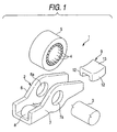
- Fig. 1 is an exploded perspective view showing an overall arrangement of a rocker arm
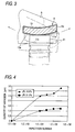
- Fig. 2 is a sectional view of the rocker arm viewed at the center in the width direction
- Fig. 3 is an enlarged sectional view showing a state of contact of the connecting wall of the rocker arm with a valve stem
- Fig. 4 is a graph showing a relation between the repetition number and the quantity of abrasion.
- reference numeral 1 defines a rocker arm made of sheet metal.
- the rocker arm is provided with a body 2.
- the body 2 includes a pair of opposed side walls 6, 7.
- the opposed side walls 6, 7 respectively include the spindle holes 6a, 7a for supporting the spindle 3 in the respective central region in the longitudinal direction.
- the spindle 3 is nonrotatably assembled to the opposed side walls 6, 7 by press fitting end portions of the spindle 3 to the opposed side walls 6, 7 to pressure contact with the circumferential wall faces of the spindle holes 6a, 7a.
- the roller 5 is externally pivotally attached to the spindle 3 via the needle rollers 4.
- the rocker arm 1 includes: a connecting wall 8 to connect both the opposed side walls 6, 7 on one side in the longitudinal direction of the opposed side walls 6, 7; and a connecting wall 9 to connect both the opposed side walls 6, 7 on the other side in the longitudinal direction of the opposed side walls 6, 7.
- the connecting wall 8 on one side constitutes a lash adjuster receiver 8 into which an upper end portion of the lash adjuster 10 is inserted, and the connecting wall 9 on the other side constitutes the valve stem receiver 9 to receive an upper end portion of the valve stem 11.
- the valve stem receiver 9 is formed separately from the opposed side walls 6, 7 and fixed between the opposed side walls 6, 7 by welding.
- the valve stem receiver 9 is formed in such a manner that a rectangular flat plate is formed into a shape, the cross section of which is substantially a C-shape.
- the valve stem receiver 9 includes a roof wall portion 13 to connect the hanging wall portions 12, 12, which are provided on opposite sides, to each other.
- the lower face of the roof wall portion 13 constitutes a valve stem sliding contact face 13a on which the upper end face 11a of the valve stem 11 comes into contact and slides.
- This valve stem sliding contact face 13a is expanded downward and formed into a crowning shape which curves in the longitudinal direction.
- the rocker arm 1 formed and operated as described above is made of low carbon steel, and the valve stem receiver 9 is also made of low carbon steel. It is preferable that the carbon content of this low carbon steel is not more than 0.4 wt%. Examples of the low carbon steel, the carbon content of which is not more than 0.4 wt%, are SCM415, SCM420, SCR420 and so forth stipulated by JIS.
- Vickers hardness H v of the surface layer portion 9a including the valve stem sliding contact face 13a is set at H v 650 to 800, and a quantity of the retained austenite ⁇ R is set at 25 to 35 vol%.
- the valve stem receiver 9 is previously welded to the opposed side walls 6, 7. Then, the heat treatment condition with respect to the rocker arm 1 is changed to adjust Vickers hardness of the surface layer portion of the valve stem sliding contact face 13a to H v 650 to 800 and adjust a quantity of the retained austenite ⁇ R to be 25 to 350 vol%.
- the heat treatment condition is changed in such a manner that the quenching temperature of the body 2 is set at a value higher than that of the conventional case and the tempering temperature of the body 2 is set at a value lower than that of the conventional case.
- the quenching temperature of the body 2 is set at a higher value as described above, a quantity of the retained austenite to be transformed into martensite can be reduced.
- the tempering temperature of the body 2 is set at a lower value as described above, the decomposition of the retained austenite is suppressed so that a quantity of the retained austenite ⁇ R can be adjusted to be 25 to 35 vol%.
- a quantity of the retained austenite ⁇ R of the valve stem receiver 9 is approximately 14%
- the quantity of the retained austenite ⁇ R of the valve stem receiver 9 is set at 25 to 35 vol%
- the quantity of the retained austenite ⁇ R of the valve stem receiver 9 is preferably set at 28 to 32 vol%. Therefore, life of the valve stem receiver 9 is prolonged. Further, when the retained austenite is decomposed, the hardness of the surface layer portion of the valve stem sliding contact face 13a is raised and it becomes difficult for the valve stem sliding contact face 13a to be plastically deformed. Accordingly, it is possible to enhance the impact resistance property, the fatigue resistance property, the abrasion resistance property and the pitching resistance property of the valve stem sliding contact face 13a.
- valve stem sliding contact face 13a when the contact surface pressure given between the valve stem sliding contact face 13a and the valve stem 11 is reduced by forming the valve stem sliding face 13a into a crowning shape and a quantity of the retained austenite ⁇ R of the valve stem sliding contact face 13a is increased as compared with that of the conventional case, the fatigue resistance property of the valve stem sliding contact face 13a can be enhanced and the occurrence of abnormal abrasion and pitching can be effectively prevented.
Landscapes
- Engineering & Computer Science (AREA)
- Mechanical Engineering (AREA)
- General Engineering & Computer Science (AREA)
- Valve-Gear Or Valve Arrangements (AREA)
- Heat Treatment Of Articles (AREA)
Applications Claiming Priority (2)
| Application Number | Priority Date | Filing Date | Title |
|---|---|---|---|
| JP2004005383A JP2005201066A (ja) | 2004-01-13 | 2004-01-13 | ロッカアーム |
| JP2004005383 | 2004-01-13 |
Publications (2)
| Publication Number | Publication Date |
|---|---|
| EP1555397A1 true EP1555397A1 (fr) | 2005-07-20 |
| EP1555397B1 EP1555397B1 (fr) | 2007-03-28 |
Family
ID=34616834
Family Applications (1)
| Application Number | Title | Priority Date | Filing Date |
|---|---|---|---|
| EP05000589A Expired - Lifetime EP1555397B1 (fr) | 2004-01-13 | 2005-01-13 | Culbuteur et méthode de fabriquer le même |
Country Status (5)
| Country | Link |
|---|---|
| US (1) | US7185619B2 (fr) |
| EP (1) | EP1555397B1 (fr) |
| JP (1) | JP2005201066A (fr) |
| CN (1) | CN1641189A (fr) |
| DE (1) | DE602005000753T2 (fr) |
Cited By (1)
| Publication number | Priority date | Publication date | Assignee | Title |
|---|---|---|---|---|
| DE102005057298A1 (de) * | 2005-12-01 | 2007-06-06 | Schaeffler Kg | Hebelartiger Nockenfolger |
Families Citing this family (5)
| Publication number | Priority date | Publication date | Assignee | Title |
|---|---|---|---|---|
| DE102010005606A1 (de) * | 2010-01-25 | 2011-07-28 | Schaeffler Technologies GmbH & Co. KG, 91074 | Nockenfolger zur Betätigung eines Gaswechselventils |
| DE102010024196A1 (de) * | 2010-06-17 | 2011-12-22 | Schaeffler Technologies Gmbh & Co. Kg | Schlepphebel für einen Ventiltrieb einer Brennkraftmaschine |
| US8627796B2 (en) | 2011-04-21 | 2014-01-14 | Eaton Corporation | Pivot foot for deactivating rocker arm |
| CN105179037A (zh) * | 2014-06-12 | 2015-12-23 | 舍弗勒技术股份两合公司 | 气门压杆 |
| CN114183217B (zh) * | 2021-10-29 | 2023-07-21 | 东风商用车有限公司 | 一种铸铁摇臂结构 |
Citations (8)
| Publication number | Priority date | Publication date | Assignee | Title |
|---|---|---|---|---|
| JPS5587809A (en) * | 1978-12-26 | 1980-07-03 | Umezawa Koji | Valve rocker material |
| JPS5913046A (ja) * | 1982-07-13 | 1984-01-23 | Daihatsu Motor Co Ltd | ロツカ−ア−ムのパツド部材 |
| JPS60125349A (ja) * | 1983-12-08 | 1985-07-04 | Toyota Motor Corp | ロッカア−ム用鋳鉄 |
| US4856469A (en) * | 1987-09-25 | 1989-08-15 | Mazda Motor Corporation | Mechanical parts of valve driving mechanism for internal combustion engine |
| JPH0642537A (ja) * | 1992-07-23 | 1994-02-15 | Nippon Seiko Kk | 転がり摺動部品 |
| JPH06129434A (ja) * | 1992-10-21 | 1994-05-10 | Nippon Seiko Kk | エンジンの動弁機構用カムフォロア装置の外輪 |
| JPH06129433A (ja) * | 1992-10-21 | 1994-05-10 | Nippon Seiko Kk | エンジンの動弁機構用カムフォロア装置の外輪 |
| JPH0754616A (ja) * | 1993-08-09 | 1995-02-28 | Koyo Seiko Co Ltd | ローラカムフォロワ |
Family Cites Families (10)
| Publication number | Priority date | Publication date | Assignee | Title |
|---|---|---|---|---|
| JPH0788851B2 (ja) * | 1987-08-25 | 1995-09-27 | 日本精工株式会社 | 転がり軸受 |
| JPS6466407A (en) | 1987-09-08 | 1989-03-13 | Honda Motor Co Ltd | Sliding member for internal combustion engine |
| JP3465112B2 (ja) * | 1991-10-08 | 2003-11-10 | 同和鉱業株式会社 | 鋼の表面硬化処理法 |
| EP0861907B1 (fr) * | 1991-12-03 | 2001-08-16 | Koyo Seiko Co., Ltd. | Eléments de palier et leur procédé de fabrication |
| JP3385341B2 (ja) | 1992-08-27 | 2003-03-10 | 光洋精工株式会社 | ロッカアームおよびロッカアーム本体の製造方法 |
| GB2278127B (en) * | 1993-05-13 | 1995-11-08 | Nsk Ltd | Rolling bearing |
| JPH11100643A (ja) * | 1997-09-25 | 1999-04-13 | Ntn Corp | 転がり軸受 |
| JP2000009136A (ja) * | 1998-06-24 | 2000-01-11 | Ntn Corp | 圧延設備のロール支持装置 |
| WO2000050781A1 (fr) * | 1999-02-22 | 2000-08-31 | Nsk Ltd. | Roulement a rouleaux et procede d'usinage d'un l'element de rouleau du roulement |
| JP2002060847A (ja) * | 2000-08-22 | 2002-02-28 | Ntn Corp | 耐熱浸炭転がり軸受部品およびその製造方法 |
-
2004
- 2004-01-13 JP JP2004005383A patent/JP2005201066A/ja active Pending
-
2005
- 2005-01-12 US US11/033,470 patent/US7185619B2/en not_active Expired - Lifetime
- 2005-01-13 CN CNA2005100044496A patent/CN1641189A/zh active Pending
- 2005-01-13 EP EP05000589A patent/EP1555397B1/fr not_active Expired - Lifetime
- 2005-01-13 DE DE602005000753T patent/DE602005000753T2/de not_active Expired - Lifetime
Patent Citations (8)
| Publication number | Priority date | Publication date | Assignee | Title |
|---|---|---|---|---|
| JPS5587809A (en) * | 1978-12-26 | 1980-07-03 | Umezawa Koji | Valve rocker material |
| JPS5913046A (ja) * | 1982-07-13 | 1984-01-23 | Daihatsu Motor Co Ltd | ロツカ−ア−ムのパツド部材 |
| JPS60125349A (ja) * | 1983-12-08 | 1985-07-04 | Toyota Motor Corp | ロッカア−ム用鋳鉄 |
| US4856469A (en) * | 1987-09-25 | 1989-08-15 | Mazda Motor Corporation | Mechanical parts of valve driving mechanism for internal combustion engine |
| JPH0642537A (ja) * | 1992-07-23 | 1994-02-15 | Nippon Seiko Kk | 転がり摺動部品 |
| JPH06129434A (ja) * | 1992-10-21 | 1994-05-10 | Nippon Seiko Kk | エンジンの動弁機構用カムフォロア装置の外輪 |
| JPH06129433A (ja) * | 1992-10-21 | 1994-05-10 | Nippon Seiko Kk | エンジンの動弁機構用カムフォロア装置の外輪 |
| JPH0754616A (ja) * | 1993-08-09 | 1995-02-28 | Koyo Seiko Co Ltd | ローラカムフォロワ |
Non-Patent Citations (7)
| Title |
|---|
| PATENT ABSTRACTS OF JAPAN vol. 004, no. 132 (M - 032) 17 September 1980 (1980-09-17) * |
| PATENT ABSTRACTS OF JAPAN vol. 008, no. 098 (C - 221) 9 May 1984 (1984-05-09) * |
| PATENT ABSTRACTS OF JAPAN vol. 009, no. 278 (C - 312) 6 November 1985 (1985-11-06) * |
| PATENT ABSTRACTS OF JAPAN vol. 013, no. 265 (M - 839) 19 June 1989 (1989-06-19) * |
| PATENT ABSTRACTS OF JAPAN vol. 018, no. 269 (M - 1609) 23 May 1994 (1994-05-23) * |
| PATENT ABSTRACTS OF JAPAN vol. 018, no. 432 (M - 1654) 11 August 1994 (1994-08-11) * |
| PATENT ABSTRACTS OF JAPAN vol. 1995, no. 05 30 June 1995 (1995-06-30) * |
Cited By (1)
| Publication number | Priority date | Publication date | Assignee | Title |
|---|---|---|---|---|
| DE102005057298A1 (de) * | 2005-12-01 | 2007-06-06 | Schaeffler Kg | Hebelartiger Nockenfolger |
Also Published As
| Publication number | Publication date |
|---|---|
| DE602005000753T2 (de) | 2008-01-10 |
| JP2005201066A (ja) | 2005-07-28 |
| US20050166879A1 (en) | 2005-08-04 |
| US7185619B2 (en) | 2007-03-06 |
| EP1555397B1 (fr) | 2007-03-28 |
| CN1641189A (zh) | 2005-07-20 |
| DE602005000753D1 (de) | 2007-05-10 |
Similar Documents
| Publication | Publication Date | Title |
|---|---|---|
| CN100584537C (zh) | 冲击扳手砧座及其形成方法 | |
| US6845686B2 (en) | Cam follower with roller | |
| US8146340B2 (en) | Link chain | |
| EP1548145B1 (fr) | Contacteur de came à galet pour moteur | |
| US20220333505A1 (en) | Roller hydraulic valve lifter bearing | |
| EP1484517A2 (fr) | Palier de roulement, contacteur de came à galet et came | |
| WO2010070958A1 (fr) | Acier de surfaçage de renfort pour structure de machine et composant en acier pour structure de machine | |
| US20020072444A1 (en) | Rocker joint silent chain | |
| EP1555397B1 (fr) | Culbuteur et méthode de fabriquer le même | |
| EP1329596A2 (fr) | Culbuteur à galet | |
| US20040000280A1 (en) | Positional fixing of a shaft | |
| CN100398856C (zh) | 装满滚子的滚动轴承和用于发动机的滚子凸轮随动件 | |
| JP2006250294A (ja) | 転がり軸受 | |
| US8328959B2 (en) | Lever-type cam follower | |
| JP2004003627A (ja) | シャフト,プラネタリギヤ装置,及びカムフォロア | |
| EP1701052B1 (fr) | Palier à roulement | |
| EP1418313B1 (fr) | Culbuteur | |
| GB2416813A (en) | Bearing assembly formed from high carbon steel | |
| JP2003328706A (ja) | ロッカーアームおよびその軸受 | |
| JP2005291342A (ja) | 針状ころ軸受 | |
| JP2004060807A (ja) | 転がり軸受 | |
| JP2008064159A (ja) | 軌道部材の製造方法、動弁装置の製造方法および軌道部材 | |
| JP2004183589A (ja) | カムフォロア装置 | |
| JP4368765B2 (ja) | ロッカーアーム用転がり軸受 | |
| JP2009236034A (ja) | タペットローラ軸受 |
Legal Events
| Date | Code | Title | Description |
|---|---|---|---|
| PUAI | Public reference made under article 153(3) epc to a published international application that has entered the european phase |
Free format text: ORIGINAL CODE: 0009012 |
|
| AK | Designated contracting states |
Kind code of ref document: A1 Designated state(s): AT BE BG CH CY CZ DE DK EE ES FI FR GB GR HU IE IS IT LI LT LU MC NL PL PT RO SE SI SK TR |
|
| AX | Request for extension of the european patent |
Extension state: AL BA HR LV MK YU |
|
| 17P | Request for examination filed |
Effective date: 20050824 |
|
| AKX | Designation fees paid |
Designated state(s): DE FR GB |
|
| RAP1 | Party data changed (applicant data changed or rights of an application transferred) |
Owner name: JTEKT CORPORATION |
|
| GRAP | Despatch of communication of intention to grant a patent |
Free format text: ORIGINAL CODE: EPIDOSNIGR1 |
|
| GRAS | Grant fee paid |
Free format text: ORIGINAL CODE: EPIDOSNIGR3 |
|
| GRAA | (expected) grant |
Free format text: ORIGINAL CODE: 0009210 |
|
| AK | Designated contracting states |
Kind code of ref document: B1 Designated state(s): DE FR GB |
|
| REG | Reference to a national code |
Ref country code: GB Ref legal event code: FG4D |
|
| REF | Corresponds to: |
Ref document number: 602005000753 Country of ref document: DE Date of ref document: 20070510 Kind code of ref document: P |
|
| ET | Fr: translation filed | ||
| PLBE | No opposition filed within time limit |
Free format text: ORIGINAL CODE: 0009261 |
|
| STAA | Information on the status of an ep patent application or granted ep patent |
Free format text: STATUS: NO OPPOSITION FILED WITHIN TIME LIMIT |
|
| 26N | No opposition filed |
Effective date: 20080102 |
|
| GBPC | Gb: european patent ceased through non-payment of renewal fee |
Effective date: 20090113 |
|
| PG25 | Lapsed in a contracting state [announced via postgrant information from national office to epo] |
Ref country code: GB Free format text: LAPSE BECAUSE OF NON-PAYMENT OF DUE FEES Effective date: 20090113 |
|
| REG | Reference to a national code |
Ref country code: FR Ref legal event code: PLFP Year of fee payment: 11 |
|
| PGFP | Annual fee paid to national office [announced via postgrant information from national office to epo] |
Ref country code: FR Payment date: 20150108 Year of fee payment: 11 |
|
| REG | Reference to a national code |
Ref country code: FR Ref legal event code: ST Effective date: 20160930 |
|
| PG25 | Lapsed in a contracting state [announced via postgrant information from national office to epo] |
Ref country code: FR Free format text: LAPSE BECAUSE OF NON-PAYMENT OF DUE FEES Effective date: 20160201 |
|
| PGFP | Annual fee paid to national office [announced via postgrant information from national office to epo] |
Ref country code: DE Payment date: 20201229 Year of fee payment: 17 |
|
| REG | Reference to a national code |
Ref country code: DE Ref legal event code: R119 Ref document number: 602005000753 Country of ref document: DE |
|
| PG25 | Lapsed in a contracting state [announced via postgrant information from national office to epo] |
Ref country code: DE Free format text: LAPSE BECAUSE OF NON-PAYMENT OF DUE FEES Effective date: 20220802 |