EP1555162A1 - Struktur zum Befestigen einen Türkabelstrang - Google Patents
Struktur zum Befestigen einen Türkabelstrang Download PDFInfo
- Publication number
- EP1555162A1 EP1555162A1 EP05290053A EP05290053A EP1555162A1 EP 1555162 A1 EP1555162 A1 EP 1555162A1 EP 05290053 A EP05290053 A EP 05290053A EP 05290053 A EP05290053 A EP 05290053A EP 1555162 A1 EP1555162 A1 EP 1555162A1
- Authority
- EP
- European Patent Office
- Prior art keywords
- grommet
- door
- face
- inner panel
- door inner
- Prior art date
- Legal status (The legal status is an assumption and is not a legal conclusion. Google has not performed a legal analysis and makes no representation as to the accuracy of the status listed.)
- Withdrawn
Links
- 229920001971 elastomer Polymers 0.000 claims description 7
- 238000000034 method Methods 0.000 claims description 6
- 239000002184 metal Substances 0.000 claims description 5
- 239000000806 elastomer Substances 0.000 claims description 3
- 239000011347 resin Substances 0.000 description 9
- 229920005989 resin Polymers 0.000 description 9
- 238000004519 manufacturing process Methods 0.000 description 6
- 238000007789 sealing Methods 0.000 description 6
- 210000000078 claw Anatomy 0.000 description 5
- 238000010276 construction Methods 0.000 description 4
- 230000001681 protective effect Effects 0.000 description 4
- 239000011800 void material Substances 0.000 description 3
- XLYOFNOQVPJJNP-UHFFFAOYSA-N water Substances O XLYOFNOQVPJJNP-UHFFFAOYSA-N 0.000 description 3
- 238000009434 installation Methods 0.000 description 2
- 238000011161 development Methods 0.000 description 1
- 230000018109 developmental process Effects 0.000 description 1
- 230000000694 effects Effects 0.000 description 1
- 238000003466 welding Methods 0.000 description 1
Images


Classifications
-
- B—PERFORMING OPERATIONS; TRANSPORTING
- B60—VEHICLES IN GENERAL
- B60R—VEHICLES, VEHICLE FITTINGS, OR VEHICLE PARTS, NOT OTHERWISE PROVIDED FOR
- B60R16/00—Electric or fluid circuits specially adapted for vehicles and not otherwise provided for; Arrangement of elements of electric or fluid circuits specially adapted for vehicles and not otherwise provided for
- B60R16/02—Electric or fluid circuits specially adapted for vehicles and not otherwise provided for; Arrangement of elements of electric or fluid circuits specially adapted for vehicles and not otherwise provided for electric constitutive elements
- B60R16/0207—Wire harnesses
- B60R16/0215—Protecting, fastening and routing means therefor
Definitions
- the present invention relates to a structure for mounting a door wire harness and a method for installing that structure.
- a door wire harness also referred to simply as a "door harness” for brevity
- the edge face of the door panel facing the corresponding edge of the body panel is usually provided with a hole through which the wire harness is passed.
- the present invention concerns in particular a system by which the wire harness is wired from a door inner panel toward the body panel.
- the door inner panel of a vehicle is arranged to be aligned with the body panel via its edge face.
- the door harness is extracted from inside the door inner panel through a hole provided in the edge face of the door inner panel, the door harness being connected to a wire harness in the body panel.
- the drawbacks of this practice are that operations of passing the door harness into the hole are carried out in the door inner panel, where the work cannot be controlled visually, and require a strong pulling force.
- a further drawback is that when a grommet (or duct) is mounted around the door harness, it is very difficult to engage it with the hole of the edge face.
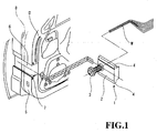
- patent document JP-A-Hei 8-33166 discloses a passwork-less grommet 1 used in a structure for mounting a door harness, as shown in Fig.1.
- this "passwork-less grommet 1" comprises a base portion 2 and a tubular portion 3 projecting therefrom.
- a door harness W is passed through this tubular portion 3.
- the base portion 2 comprises a pair of fitting portions 4 at its top and bottom ends when viewed in Fig.1.
- the door inner panel D into which "the passwork-less grommet 1" is mounted, has an edge face 5 that confronts a corresponding edge of the body panel when the door is closed.
- the edge face 5 comprises a slide channel 6.
- This slide channel 6 has confronting sidewalls (top and bottom sidewalls in Fig.1), each of which is provided with a grooved portion 7 adapted to receive the corresponding fitting portions 4.
- the door harness W is initially placed near the base portion 2 of the grommet 1, and inserted into the tubular portion 3. Then, the fitting portions 4 are inserted into the grooved portion 7, so that the passwork-less grommet 1 fits into the slide channels 6. Thereafter, a weather strip 8 is installed from above the passwork-less grommet 1.
- the slide channels 6 and the grooved portions 7 are formed in the edge face of the door inner panel D by stamping. This poses problems in that stamping out such a complex configuration is a very difficult and costly task. Moreover, such a fitting structure cannot secure a good sealing.
- a patent document JP-A-Hei 11-20573 discloses a "passwork-less" grommet 1 used in a structure for mounting a door harness, as shown in Figs.2A and 2B.
- this passwork-less grommet 1 comprises a cylindrical bellows portion 60, through which is passed the door harness W when it is pulled out from the door inner panel D.
- This grommet 1 also comprises a mounting panel 62 that is formed of a substantially flat sheet bent into an L shape. This mounting panel 62 is placed along the comer portion formed by respectively the inward face and edge face of the door inner panel D, where the door harness W can pass inside it.
- the door harness W is then protected by a protective cover 64 applied from the inward side (compartment side). Further, a weather strip 65 is mounted across the passwork-less grommet 1.
- the door harness W is not pulled out from the hole provided in the door inner panel D as in the past. Instead, the door harness W can be wired from the inward face of the door inner panel D to its edge face along the comer portion, and extended toward the body panel B. Further, the direction of the door harness W is changed upwardly or downwardly, at the fulcrum position of the hinge between the door and the vehicle body. Accordingly, when the door is opened or closed, the door harness W is twisted, but not stretched or compressed.
- the above structure requires the bellows portion 60, the mounting panel 62 and the protective cover 64 to install the door harness W in the door inner panel D.
- Such a design increases the number of component parts, and thus costs, and assembly work becomes complicated.
- the present invention is intended to solve the above-mentioned problems, and provides a structure in which the grommet or duct equipped with the door harness can be fixed easily with the door inner panel, so that door harness installation costs are lowered and the installing operations are made easier.
- a structure for wiring a door harness from a door inner panel toward a body panel in a vehicle the door harness being mountable into a grommet.
- the door inner panel has a portion proximal to the body panel.
- the proximal portion is recessed and the recessed portion comprises grommet-holding means, such that the grommet can be fixed into the recessed portion from outside the door inner panel.
- the door inner panel comprises an inward face confronting the compartment of the vehicle.
- the portion proximal to the body panel comprises a weather strip and the grommet is installed farther from the inward face than the weather strip is.
- the door inner panel has an inward face confronting the compartment of a vehicle, an edge face confronting a body panel, and a comer zone formed between the inward face and the edge face;
- the recessed portion is formed in the comer zone and comprises a portion at the edge face with a periphery and a portion at the inward face, and the grommet-holding means are provided in the portion at the edge face;
- the grommet comprises a substantially flat portion having first and second faces, a side face and at least one bore portion;
- the grommet further comprises a first tubular portion proximal to the body panel and at least one second tubular portion distal from the body panel, the first and second tubular portions projecting from the first face of the substantially flat portion and communicating through the at least one bore portion; whereby the grommet is fixed to the door inner panel by the grommet-holding means.
- the grommet-holding means comprises a shouldered section formed in the periphery and the shouldered section is fitted with a linking frame comprising ribbed or grooved guides.
- the grommet comprises a housing having a substantially flat rectangular shape which has the first and second faces, longitudinal side faces provided with respective grooved or ribbed guides, whereby the grommet is fitted to the recessed portion in a folded state, such that the grooved or ribbed guides of the grommet fit with the ribbed or grooved guides of the linking frame and the second tubular portion projects along the inward face.
- the linking frame has substantially U-shaped configuration with two arm portions, and the arm portions extend from the shouldered section of the recessed portion beyond the inward face, thereby forming a protruded guide and, when the grommet comprises grooved guides, the ribbed guides of the arm portions fit therewith.
- the first tubular portion comprises a bellows section and an end portion with a stopper, which engages with a hole in the body panel
- the at least one second tubular portion comprises at least one dividing wall so as to form a plurality of longitudinal compartments, whereby the electrical cables in the door harness can be divided into the longitudinal compartment.
- the at least one second tubular portion may comprise a plurality of second tubular portions, whereby the electrical cables in the door harness can be divided into the longitudinal compartment.
- the grommet may comprise a clip and the portion at the inward face of said recessed portion may comprise a clip hole for hooking said clip.
- the linking frame is made of a metal.
- the grommet-holding means comprises a substantially round hole with a periphery formed in the portion at the edge face, and the substantially flat portion of the grommet comprises a disk-like portion with a side face.
- the disk-like portion comprises first and second bore portions that cross from the first face to the second face, wherein the side face comprises a side groove adapted to engage with the periphery of the substantially round hole, whereby the door harness can be passed through the second tubular portion and second bore portion, then turned into the first bore portion and first tubular portion.
- the grommet-holding means comprises a substantially round hole with a periphery formed in the portion at the edge face
- substantially flat portion of the grommet comprises a disk-like portion with a side face and the disk-like portion comprises a bore portion that communicates with the first and second tubular portions inside the disk-like portion, wherein the side face comprises a side groove adapted to engage with the periphery of the substantially round hole, whereby the door harness can be passed through the second tubular portion, the bore portion and the first tubular portion.
- the side groove of said disk-like portion forms an annular seal lip adjacent the first face adapted to be tightly attached to the portion at the edge face of the recessed portion of the door inner panel, a weather strip passing on the first face of the disk-like portion between the first and second tubular portions.
- the body panel comprises a hole and the first tubular portion has an exit end provided with a stopper, wherein the stopper is engageable with said hole, whereby the door harness is wired through the recessed portion and pulled out from the first tubular portion of the grommet and the door harness is wired to the body panel.
- the grommet is preferably made of rubber or an elastomer.
- the invention also relates to a door harness wiring system comprising a structure for mounting a door harness from a door inner panel toward a body panel in a vehicle.
- the door inner panel has a portion proximal to the body panel, and the door harness is mountable into a grommet.
- the proximal portion is recessed and the recessed portion comprises grommet-holding means, whereby the grommet can be fixed into the recessed portion from outside the door inner panel.
- the invention further relates to a method for mounting a door harness from a door inner panel toward a body panel in a vehicle, the method comprising the steps of:
- a door harness fitting recess is provided in the door inner panel on the one hand, and the grommet is placed and fixed at a given position of a detachable panel, on the other.
- the detachable panel is then engaged with the fitting recess (recessed area) in the door inner panel.
- the grommet is easily affixed to the door inner panel.
- the door harness can be thus easily wired from the door inner panel to the body panel.
- the linking frame in order to mount the grommet or duct in the door inner panel, is provided with ribbed guides, for instance, which simply fit into the grooved guides of the grommet, and the grommet is then slid along the ribbed guides.
- the ribbed guides and the grooved guides are hermetic, they secure a good sealing capacity around the grommet.
- the tubular portion is rendered more resistant to deformation by the provision of a dividing wall.
- the tubular portion can then be made flat, and the door harness can be wired even in small spaces, such as in the door inner panel, or between the detachable panel and the trim.
- each tubular portion can also be made smaller and/or flat.
- the linking frame is fixed into the door-harness fitting recess in the door inner panel, and the grommet/duct is fitted to the linking frame and fixed thereto.
- the grommet/duct can thus be easily affixed to the door inner panel, whereby the door harness is wired from the door inner panel to the body panel.
- the position of door inner panel where the grommet is mounted is simply constituted by the fitting recess, and the linking frame is fixed thereto. It is thus no longer necessary to stamp out a complicated door inner panel structure. The number of working steps and manufacturing costs of the structure are thus reduced.
- the grooved guides of the grommet/duct are fitted, from outside, to the periphery of the substantially round hole provided in the edge face of the door inner panel.
- the above fitting means secure a good sealability between the grommet and the door inner panel, and require no other means for fixing them, such as bolting.
- the grommet/duct is integrally formed, the number of component parts is reduced and the manufacturing costs of the grommet can be lowered.
- the first tubular portion is provided farther to the exterior of the vehicle compartment than the weather strip is. Nonetheless, good sealing can be secured, because the side groove of the grommet fits tightly with the periphery of the round hole, and the edge face of the door inner panel is adhered by the seal lip projecting from the disk-like portion.
- the door harness is wired toward the body panel from outside the weather strip, water sealing is secured. Furthermore, in the above construction, the door harness can be wired at the position at the fulcrum line of hinge between the door and the car body. It is therefore unnecessary to provide stretching and/or compressing capability to the door harness for adapting to the opening or closing of the door, and the configuration of the structure can be simplified.
- the grooved guides of the grommet/duct are simply fitted from outside to the periphery of the substantially round hole formed in the edge face of the door inner panel.
- the work operations of the past i.e. passing the door harness into the through-hole from inside the door inner panel, can thus be obviated, and operations of pulling out the door harness toward the body panel are greatly facilitated.
- the word "grommet” used includes not only the grommets in a classical sense, but also those comprising auxiliary component parts not limited to protecting the wire harness.
- the grommet here generally takes the form of a duct or tube for housing wires of a wire harness, for instance as shown in the figures, the terms “grommet", “duct”, “tube”, or the like being considered in the present specification as interchangeable for designating that part, as shall be understood by the person skilled in the art of wire harness installation.
- Figs. 3 to 8 show a structure 10 for mounting a door harness W according to a first embodiment of the invention.
- the door inner panel 11 comprises an inward face 11a confronting the vehicle's compartment, and an edge face 11b confronting the corresponding edge face of a vehicle body panel 16 when the door is closed.
- a weather strip 18 extends along a longitudinal line on the edge face 11b, and a door harness W is wired toward the body panel 16, e.g. via a position farther away from the inward face than the weather strip is 18, whereby the weather strip is innermost compared to the aforementioned wiring position.
- the door inner panel 11 is provided with a recessed portion 30 for engaging the door harness, formed at the comer of the inward face 11 a and the edge face 11b.
- the outer periphery of the recessed portion 30 at the door panel's edge face 11b has a shouldered section 31 for receiving a linking frame. The depth of this shouldered section 31 is less than that of the recessed portion 30 overall.
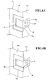
- the inward-face side section of the recessed portion 30 (see Figs.4A and 4B) is provided with a clip-fixing hole 32 which is adapted to engage with a stopper clip 29 of the grommet 20 (see Fig.5A), when the latter is bent.
- the inward face 11a of the door inner panel comprises a recessed area 12, such that the periphery of that recessed area 12 forms a outer frame.
- the outward face of the door inner panel 11 is provided with an outer panel 14 made of metal.
- a linking frame 40 is fixed to the shouldered section 31 by spot welding.
- the linking frame 40 is made e.g. of metal and has a substantially U-shape, with two arm portions 40b. As shown in Fig.4A, the edges of the two arm portions 40b project beyond a comer section 30b of the recessed portion 30, so as to define protruded guides 41.
- the thickness of the linking frame 40 is substantially the same as the depth of the shouldered section 31. Accordingly, when the linking frame 40 is fitted into the shouldered section 31, the edge face 11b of door inner panel 11 and the arm portions 40b of the linking frame 40 form a uniform surface.
- the grommet 20 is made e.g. of rubber, and fits into the recessed portion 30.
- the grommet 20 comprises a substantially flat portion 21 having a rectangular shape, through which the door harnesses W is passed.
- the grommet 20 further comprises first and second tubular portions 22 and 23 which project from the longitudinal end portions of the substantially flat portion 21.
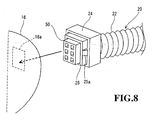
- the first tubular portion 22 has a bellows section and projects toward the body panel 16 when mounted. Its end portion is provided with a connector housing 24.
- the latter contains an inner frame 25, e.g. made of resin, equipped with stopper claws 25a, such that both the inner frame 25 and the stopper claws 25a project outwardly beyond the connector housing 24.
- the second tubular portion 23 has a substantially oval-shaped cross-section, as shown in Fig.5C, and projects along the inward face 11a of the door inner panel 11 when mounted (see Fig.6B).
- a dividing wall 26 bridges opposite points of the second tubular portion 23 where the oval cross-section is narrowest, as shown in Fig. 5C.
- the substantially flat portion 21 contains an elongate cavity 27 (Fig.5B) which connects the tubular hole of the first tubular portion 22 to that of the second tubular portion 23.
- the door harness W is passed through these thus-defined void passages to be mounted into the grommet 20. Further, the longitudinal side edges of the flat portion 21 are respectively provided with grooved guides 28.
- the bottom face of the flat portion 21 (as depicted in Fig.5A and 5B) is provided with the aforementioned stopper clip 29 at a position substantially opposite to the connection point of the second tubular portion 23.
- This stopper clip 29 engages the grommet 20 with the door inner panel 11 through the clip-fixing hole 32 (Figs.4A, 4B).
- the door harness W in accordance with the present invention is mounted in the following manner.
- the door harness D is passed through the grommet 20, and a connector 50 is fixed to the end of the door harness W.
- the connector 50 is fitted into the resin inner frame 25 contained in the connector housing 24, so that the grommet 20 is mounted around the door harness W.
- the door harness W extending from the grommet 20 is then fixed to the detachable panel 13, e.g. made of resin, by a clamp 19 (see Fig.3).
- the ribbed guides 41 (see also Fig.4B) in the linking frame 40, affixed to the edge face 11b of the door inner panel 11, receives the grooved guides 28.
- the grommet 20 is slid along those guides until the leading edge of the flat portion 21, where the first tubular portion 22 is provided, abuts against the internal face of the linking frame 40.
- the tail part of the flat portion 21 is bent toward the inward face 11a of the door inner panel 11, and fitted into the inward-face side section of the recessed portion 30. Thereafter, the stopper clip 29 of the grommet 20 is engaged into the clip-fixing hole 32, so that the grommet 20 engages with the door inner panel 11.
- the detachable panel 13 is fitted into the recessed area 12 of the door inner panel 11 (Fig.3).
- a trim (not shown in the Figs.) is then installed from over the inward face 11a of the door inner panel 11, and the grommet 20 fitted in the recessed portion 30.
- the grommet 20 is firmly fixed in the recessed portion 30 under the trim.
- the weather strip 18 extends along the (vertical) longitudinal direction of the edge face 11b of the door inner panel 11. It may be located closer to the vehicle's compartment than the first tubular portion 22 of the grommet 20 is.
- the first tubular portion 22 of the grommet 20 is mounted on the door inner panel 11 and pulled toward the body panel 16.
- the resin inner frame 25 mounted on the grommet 20 is then inserted into the hole 16a of the body panel 16, and is engaged therein by means of the stopper claws 25a.
- the connector 50 at the free end of the first tubular portion 22 is thus connected to the corresponding section of wire harness (not shown in the Figs.) in the body panel 16.
- the linking frame 40 is fixed in the recessed portion 30 in the door inner panel 11. Since the grommet 20 is already affixed to the linking frame 40 at a predetermined position, the door harness W can be easily wired from the door inner panel 11 to the body panel 16, by merely fixing the grommet 20 to the door inner panel 11.
- the door harness W is drawn out from the door inner panel 11 toward the body panel 16 in the area outside the weather strip 18, relative to the vehicle's compartment. Nonetheless, water sealing is not damaged, because the grommet 20 is very closely attached to the linking frame 40.
- the harness-receiving recessed portion 30 (Figs. 6A and 6B) is provided in a simple manner at the position of door inner panel 11 where the grommet 20 is to be mounted, and the linking frame 40 is fixed thereto. Accordingly, it is no longer necessary to stamp out a complicated shape in the door inner panel 11. As a result, the assembling steps are simplified and manufacturing costs of the structure are lowered.
- FIG.9 shows a variant of the first embodiment of the present invention, in which only the constructions of the linking frame and grommet differ from those of the first embodiment.
- a linking frame 40' is made e.g. of a metal sheet having a U-shape with two arm portions 40b', and the opposing inward edges of the two arm portions 40b' are bent to form grooved guides 42'.
- the grommet 20' comprises ribbed guides 43' along each of the longitudinal sidewalls of the flat portion 21', and the ribbed guides 43' fit into the grooved guides 42'. Further, there are provided e.g. three tubular portions 23' projecting from the first face of the flat portion 21'.
- the linking frame 40' is affixed in the recessed portion 30' installed in the door inner panel 11. Since the ribbed guides 43' of the grommet 20' are fitted into the grooved guides 42' of the linking frame 40 and positioned and fixed therein, the door harness W can be easily wired from the door inner panel 11 to the body panel 16, by a simple action of inserting the grommet 20' into the door inner panel 11.
- the door harness W can easily be made substantially flat, and thus more amenable to being wired in a small space, such as one formed between the detachable panel and the trim.
- the number of tubular portions 23' of the grommet 20' is not limited to three, but may be 2 or 4 or more.
- Figs. 10 to 13 show a structure 10 for wiring a door harness W according to a second embodiment of the invention.
- the door inner panel 11 comprises an inward face 11a confronting the vehicle's compartment, and an edge face 11b confronting a corresponding edge face of the body panel 16 when the door is closed.
- a weather strip 18 extends along a longitudinal (vertical) direction of the edge face 11b, and a door harness W is wired to the body panel 16 from outside the weather strip, relative to the inward face of the door inner panel 11.
- the door inner panel 11 is provided with a recessed portion 30, in the comer formed between the inward face 11a and the edge face 11b. Further, a hole 31 for fitting the grommet is provided through the base of the recessed portion 30, at the edge-face side section of the recessed portion 30.
- the hole 31 may have a substantially round shape.
- the grommet 20 e.g. made of rubber or elastomer, and to be fitted into the hole 31, comprises a substantially disk-like portion 21 having opposite first and second faces, and a first tubular portion 22 and a second tubular portion 23 that protrude from respective positions distal to each other on the first face of the disk-like portion 21.
- the first tubular portion 22 has a bellows section and, when installed, protrudes toward the body panel 16.
- One end of the first tubular portion 22 comprises a connector housing 24, from which extends outwardly an inner frame 25, e.g. made of resin, comprising stopper claws 25a.
- the second tubular portion 23 has a cross-section defining a circular ring and, when installed, allows the door harness W to extend along the inward face 11a of the door inner panel 11.
- the disk-like portion 21 comprises two holes 26' and 27' which extend from the corresponding first and second tubular portions 22 and 23 and attain the second face of the disk-like portion 21 (see Fig.11B).
- the side face of the disk portion 21 comprises a grooved guide 28 that engages with the hole 31.
- the grooved guide 28 thus forms two ribs, including the rib adjacent the first face of the disk-like portion 21.
- the external end of the latter rib is tapered outwardly in the diametrical direction (Fig.11B), thereby forming a seal lip 29' adapted to fit to the periphery of the hole 31.
- the procedure for mounting the door harness W with this second embodiment is as follows.
- the door harness W is introduced into the second tubular portion 23 and the tubular hole 26', pulled out from the second face of the disk portion 21, then turned, and inserted into the tubular hole 27' and the first tubular portion 22.
- the connector 50 is connected to the door harness W.
- the connector 50 is then fitted into the inner frame 25, e.g. made of resin, contained in the connector housing 24 of the grommet 20.
- the door harness W extending from the grommet 20 is fixed to the detachable panel 13, e.g. made of resin, by clamp 19.
- the detachable panel 13 is integrally provided with a holding portion, the door harness W is fixedly held by this holding portion.
- the detachable panel 13 is fixed into the recessed area 12 of the door inner panel 11.
- the door harness W is wired over the inward face 11a of the door inner panel 11 and passed into the inward-face section of the recessed portion 30. Then, the grooved guide 28 of the grommet 20 is engaged with the periphery of the hole 31 provided in the edge-face section of the recessed portion 30 of the door inner panel 11, whereby the grommet 20 engages with the door inner panel 11. In this state, the first tubular portion 22 is disposed farther from the vehicle compartment, relative to the second tubular portion 23.
- the trim (not shown) is then covered onto the detachable panel 13, and the weather strip 18 is mounted on the edge face 11b of the door inner panel 11, such that it runs along the edge face 11b and passes between the first and the second tubular portions 22 and 23.
- the first tubular portion 22 of grommet 20 mounted on the door inner panel 11 is pulled out toward the body panel 16, and the stopper claws 25a of the resin inner frame 25 is inserted into the hole 16a of the body panel 16 and engaged therein.
- the connector 50 at the edge of the door harness W is connected to a wire harness (not shown) in the body panel 16.
- the grommet 20 can be easily fixed to the door inner panel 11, by merely fitting the grommet 20 into the hole 31 in the door inner panel 11, whereby the door harness W is wired from the door inner panel 11 to the body panel 16. Further, as the grommet 20 is an integrally molded product, the number of component parts and assembly steps can be reduced. Consequently, the manufacturing costs of the total structure are also cut down.
- the door harness W exiting toward the body panel 16 is placed farther from the inward face 11a than the weather strip 18 is.
- water sealing is nonetheless secured by the tight engagement of the seal lip 29' of the grommet 20 with the periphery of the hole 31.
- the grommet 20 may have another shape than the round one, eg. an oval or elliptical shape.
- the holes in the substantially disk-like portion may be a void passage connecting the bore portion in the first tubular portion and that of the second tubular portion. Then, the door harness W is not drawn out from the second face of the disk portion, but passed through this void passage in the disk-like portion.
Landscapes
- Engineering & Computer Science (AREA)
- Mechanical Engineering (AREA)
- Installation Of Indoor Wiring (AREA)
Applications Claiming Priority (4)
| Application Number | Priority Date | Filing Date | Title |
|---|---|---|---|
| JP2004006876A JP2005199804A (ja) | 2004-01-14 | 2004-01-14 | ドアハーネスの取付構造およびドアハーネスの取付方法 |
| JP2004007097A JP2005199812A (ja) | 2004-01-14 | 2004-01-14 | ドアハーネスの取付構造 |
| JP2004007097 | 2004-01-14 | ||
| JP2004006876 | 2004-01-14 |
Publications (1)
| Publication Number | Publication Date |
|---|---|
| EP1555162A1 true EP1555162A1 (de) | 2005-07-20 |
Family
ID=34622259
Family Applications (1)
| Application Number | Title | Priority Date | Filing Date |
|---|---|---|---|
| EP05290053A Withdrawn EP1555162A1 (de) | 2004-01-14 | 2005-01-10 | Struktur zum Befestigen einen Türkabelstrang |
Country Status (2)
| Country | Link |
|---|---|
| US (1) | US7053305B2 (de) |
| EP (1) | EP1555162A1 (de) |
Cited By (2)
| Publication number | Priority date | Publication date | Assignee | Title |
|---|---|---|---|---|
| EP2096001A4 (de) * | 2006-12-06 | 2010-11-17 | Sumitomo Wiring Systems | Äusseres schutzmaterial für türkabelbaum und drahtanordnungsstruktur für den türkabelbaum |
| US11485202B2 (en) | 2017-12-06 | 2022-11-01 | Autonetworks Technologies, Ltd. | Door module and door module fixture |
Families Citing this family (19)
| Publication number | Priority date | Publication date | Assignee | Title |
|---|---|---|---|---|
| US20020115056A1 (en) * | 2000-12-26 | 2002-08-22 | Goodlett David R. | Rapid and quantitative proteome analysis and related methods |
| GB0305796D0 (en) | 2002-07-24 | 2003-04-16 | Micromass Ltd | Method of mass spectrometry and a mass spectrometer |
| JP4406374B2 (ja) * | 2005-01-07 | 2010-01-27 | 矢崎総業株式会社 | グロメット組立体の組付構造 |
| DE102005043177A1 (de) * | 2005-09-09 | 2007-03-29 | Johnson Controls Interiors Gmbh & Co. Kg | Innerverkleidung einer Kraftfahrzeugtür mit Kabelübergang |
| EP1876067B1 (de) * | 2006-07-06 | 2011-09-14 | Yazaki Corporation | Wasserabdichtungskonstruktion für einen Kabelbaum |
| US7701625B2 (en) * | 2006-09-21 | 2010-04-20 | Xerox Corporation | Critical color tolerance guide for printers |
| US7615713B2 (en) * | 2006-12-05 | 2009-11-10 | Delphi Technologies, Inc. | Mounting structure for wiring harness |
| JP2009036841A (ja) * | 2007-07-31 | 2009-02-19 | Brother Ind Ltd | 画像形成装置 |
| US7943854B1 (en) | 2008-09-19 | 2011-05-17 | Yazaki North America | Wire twist optimizing grommet |
| US8011720B2 (en) * | 2009-04-09 | 2011-09-06 | Toyota Motor Engineering & Manufacturing North America, Inc. | Apparatus to aid in the assembly of cables and electrical components |
| US8690273B2 (en) * | 2010-03-26 | 2014-04-08 | Whirlpool Corporation | Method and apparatus for routing utilities in a refrigerator |
| DE202010007390U1 (de) | 2010-05-25 | 2011-09-28 | Brose Fahrzeugteile Gmbh & Co. Kommanditgesellschaft, Hallstadt | Türmodul für eine Fahrzeugtür |
| US10099560B2 (en) | 2011-01-26 | 2018-10-16 | Toyota Motor Engineering & Manufacturing North America, Inc. | System and method for maintaining the speed of a vehicle |
| US8648259B2 (en) | 2012-01-12 | 2014-02-11 | Yazaki North America, Inc. | Accordion-style grommet with shape-influencing stiffeners |
| US8785779B1 (en) * | 2012-02-06 | 2014-07-22 | The Boeing Company | Snap-in raceway |
| CN106132742B (zh) * | 2014-03-28 | 2018-08-28 | 本田技研工业株式会社 | 车辆用门的构造 |
| EP3098819B1 (de) * | 2015-05-28 | 2017-07-05 | Lapp Engineering & Co. | Kabel |
| JP6471909B2 (ja) * | 2016-04-07 | 2019-02-20 | 住友電装株式会社 | ワイヤハーネス |
| US10525908B2 (en) * | 2018-05-17 | 2020-01-07 | Kiekert Ag | Motor vehicle latching system with cable duct |
Citations (5)
| Publication number | Priority date | Publication date | Assignee | Title |
|---|---|---|---|---|
| JPH11321483A (ja) * | 1998-05-11 | 1999-11-24 | Yazaki Corp | ドアハーネス及びドアハーネスの形成方法 |
| EP1108620A2 (de) * | 1999-12-14 | 2001-06-20 | Sumitomo Wiring Systems, Ltd. | Türtülle |
| JP2002027640A (ja) * | 2000-07-03 | 2002-01-25 | Yazaki Corp | 貫通レスグロメットの固定構造 |
| US20020014789A1 (en) * | 1998-12-09 | 2002-02-07 | Yazaki Corporation | Grommet and fixing structure thereof |
| EP1236599A1 (de) * | 2001-02-21 | 2002-09-04 | Sumitomo Wiring Systems, Ltd. | Verlegungssystem für einen Tür-Kabelbaum |
Family Cites Families (9)
| Publication number | Priority date | Publication date | Assignee | Title |
|---|---|---|---|---|
| ES2074894T3 (es) * | 1991-10-08 | 1995-09-16 | Controle Measure Regulation | Conducto de distribucion mixto para cables de mediciones de corriente debil y cables de encendido de alta tension de motores de explosion. |
| JP2576564Y2 (ja) | 1993-01-20 | 1998-07-16 | 住友電装株式会社 | グロメット |
| JP3422379B2 (ja) | 1994-07-12 | 2003-06-30 | カルソニックカンセイ株式会社 | 車両用ドアハーネス配索構造 |
| JP3175579B2 (ja) | 1996-03-11 | 2001-06-11 | 住友電装株式会社 | 自動車ドア用ワイヤハーネスの取付構造および取付方法 |
| JP3384256B2 (ja) | 1996-08-01 | 2003-03-10 | 住友電装株式会社 | グロメットおよび該グロメットの製造方法 |
| JP3467172B2 (ja) | 1997-06-27 | 2003-11-17 | 矢崎総業株式会社 | ワイヤハーネスの取付け構造 |
| US6166007A (en) | 1998-07-02 | 2000-12-26 | Sodemann; Klaus | Antimicrobial locks comprising taurinamide derivatives and carboxylic acids and/or salts thereof |
| JP3620345B2 (ja) | 1999-05-27 | 2005-02-16 | 住友電装株式会社 | グロメット |
| US20020147789A1 (en) * | 2001-04-05 | 2002-10-10 | Higbee Robert N. | Virtual filing system |
-
2005
- 2005-01-10 EP EP05290053A patent/EP1555162A1/de not_active Withdrawn
- 2005-01-13 US US11/033,742 patent/US7053305B2/en not_active Expired - Fee Related
Patent Citations (5)
| Publication number | Priority date | Publication date | Assignee | Title |
|---|---|---|---|---|
| JPH11321483A (ja) * | 1998-05-11 | 1999-11-24 | Yazaki Corp | ドアハーネス及びドアハーネスの形成方法 |
| US20020014789A1 (en) * | 1998-12-09 | 2002-02-07 | Yazaki Corporation | Grommet and fixing structure thereof |
| EP1108620A2 (de) * | 1999-12-14 | 2001-06-20 | Sumitomo Wiring Systems, Ltd. | Türtülle |
| JP2002027640A (ja) * | 2000-07-03 | 2002-01-25 | Yazaki Corp | 貫通レスグロメットの固定構造 |
| EP1236599A1 (de) * | 2001-02-21 | 2002-09-04 | Sumitomo Wiring Systems, Ltd. | Verlegungssystem für einen Tür-Kabelbaum |
Non-Patent Citations (2)
| Title |
|---|
| PATENT ABSTRACTS OF JAPAN vol. 2000, no. 02 29 February 2000 (2000-02-29) * |
| PATENT ABSTRACTS OF JAPAN vol. 2002, no. 05 3 May 2002 (2002-05-03) * |
Cited By (3)
| Publication number | Priority date | Publication date | Assignee | Title |
|---|---|---|---|---|
| EP2096001A4 (de) * | 2006-12-06 | 2010-11-17 | Sumitomo Wiring Systems | Äusseres schutzmaterial für türkabelbaum und drahtanordnungsstruktur für den türkabelbaum |
| US11485202B2 (en) | 2017-12-06 | 2022-11-01 | Autonetworks Technologies, Ltd. | Door module and door module fixture |
| US11801735B2 (en) | 2017-12-06 | 2023-10-31 | Autonetworks Technologies, Ltd. | Door module and door module fixture |
Also Published As
| Publication number | Publication date |
|---|---|
| US20050150678A1 (en) | 2005-07-14 |
| US7053305B2 (en) | 2006-05-30 |
Similar Documents
| Publication | Publication Date | Title |
|---|---|---|
| EP1555162A1 (de) | Struktur zum Befestigen einen Türkabelstrang | |
| EP1363375B1 (de) | Kabelbaumschutz | |
| JP3319454B2 (ja) | ドア用グロメット | |
| EP1125797B1 (de) | Büchse | |
| US5716044A (en) | Vehicle door and wire harness arrangement | |
| US6312046B1 (en) | Grommet and fixing structure thereof | |
| US6339196B1 (en) | Grommet | |
| US20040137197A1 (en) | Door opening trim weather strip for motor vehicle | |
| US6536835B2 (en) | Door-harness wiring system and method | |
| AU4446702A (en) | Grommet equipped with resin inner sleeve and method of installing the grommet | |
| JP2003032853A (ja) | グロメットの取付構造 | |
| JP5313631B2 (ja) | 内装部材の取付構造 | |
| JPH08335419A (ja) | グロメットの取付構造 | |
| JP2008206370A (ja) | グロメット用ガイドプロテクタ | |
| JP2013021791A (ja) | グロメット | |
| JPH08331732A (ja) | ワイヤハーネスの車体貫通構造 | |
| JP3711087B2 (ja) | プロテクタの取付構造 | |
| JP2022130819A (ja) | グロメットアセンブリ及びワイヤハーネス | |
| JPS6128340Y2 (de) | ||
| US20250074165A1 (en) | Door hole cover | |
| KR200170697Y1 (ko) | 자동차의 벨트 가이드 설치 구조 | |
| JP2015042048A (ja) | ドア用グロメット及びグロメット付ワイヤーハーネス | |
| JP2002114113A (ja) | グロメットのドア取付構造 | |
| JP2008207741A (ja) | ドアハーネスの配索構造 | |
| JP2005199804A (ja) | ドアハーネスの取付構造およびドアハーネスの取付方法 |
Legal Events
| Date | Code | Title | Description |
|---|---|---|---|
| PUAI | Public reference made under article 153(3) epc to a published international application that has entered the european phase |
Free format text: ORIGINAL CODE: 0009012 |
|
| AK | Designated contracting states |
Kind code of ref document: A1 Designated state(s): AT BE BG CH CY CZ DE DK EE ES FI FR GB GR HU IE IS IT LI LT LU MC NL PL PT RO SE SI SK TR |
|
| AX | Request for extension of the european patent |
Extension state: AL BA HR LV MK YU |
|
| 17P | Request for examination filed |
Effective date: 20050808 |
|
| AKX | Designation fees paid |
Designated state(s): DE FR GB IT |
|
| GRAP | Despatch of communication of intention to grant a patent |
Free format text: ORIGINAL CODE: EPIDOSNIGR1 |
|
| STAA | Information on the status of an ep patent application or granted ep patent |
Free format text: STATUS: THE APPLICATION HAS BEEN WITHDRAWN |
|
| 18W | Application withdrawn |
Effective date: 20080822 |