EP1553246B1 - Mitnehmerverbindung - Google Patents
Mitnehmerverbindung Download PDFInfo
- Publication number
- EP1553246B1 EP1553246B1 EP04028783A EP04028783A EP1553246B1 EP 1553246 B1 EP1553246 B1 EP 1553246B1 EP 04028783 A EP04028783 A EP 04028783A EP 04028783 A EP04028783 A EP 04028783A EP 1553246 B1 EP1553246 B1 EP 1553246B1
- Authority
- EP
- European Patent Office
- Prior art keywords
- driver
- connection according
- nut
- pin
- driver connection
- Prior art date
- Legal status (The legal status is an assumption and is not a legal conclusion. Google has not performed a legal analysis and makes no representation as to the accuracy of the status listed.)
- Expired - Lifetime
Links
Images


Classifications
-
- E—FIXED CONSTRUCTIONS
- E05—LOCKS; KEYS; WINDOW OR DOOR FITTINGS; SAFES
- E05B—LOCKS; ACCESSORIES THEREFOR; HANDCUFFS
- E05B3/00—Fastening knobs or handles to lock or latch parts
- E05B3/02—Fastening knobs or handles to the spindle by pinning or riveting
-
- E—FIXED CONSTRUCTIONS
- E05—LOCKS; KEYS; WINDOW OR DOOR FITTINGS; SAFES
- E05B—LOCKS; ACCESSORIES THEREFOR; HANDCUFFS
- E05B63/00—Locks or fastenings with special structural characteristics
- E05B63/0056—Locks with adjustable or exchangeable lock parts
- E05B63/006—Locks with adjustable or exchangeable lock parts for different door thicknesses
Definitions
- the invention relates to a driver connection according to the preamble of claim 1.
- Such compounds are mainly used for window and door fittings, which generally has the problem that the frame or door thickness can be completely different.
- a pusher pin or mandrel is described for example in DE-U1-1 705 743, which is firmly connected to a handle.
- a compensation of door thickness deviations should be possible with a longitudinally inserted into the mandrel / pusher pin coil spring, which is accessible through lateral slots therein.
- a retaining pin is driven transversely through the handle neck and through the spring whose turns should be so close together that the retaining pin wedges. But because it is always visible and possibly overhanging with its ends, this is not an aesthetically satisfying solution; also a risk of injury can not be ruled out.
- the assembly requires greater effort, and it depends on the spring design, whether the retaining pin is ever collectible and then unfolds its function.
- DE-C2-197 07 836 also discloses a pusher connection with a lock nut by a cross-shaped mandrel, which is designed as a square pin. It is firmly connected to the neck of a first door handle and carries at its other end, facing a second door handle, pinned to the drive pin or mandrel outer sleeve.
- a spring-loaded bayonet lock In the provided with an inner sleeve neck of the second handle is a spring-loaded bayonet lock, but does not allow mandrel length compensation.
- a fitting with a stopper body e.g. a rosette, mounted on the outside or profile top of a window or a door at the level of an internal gear or lock nut.
- the arrangement of the required mounting holes is standardized with respect to the position of a square, which passes through the nut as a driver. Different window profiles or door thicknesses but cause unequal axial distances of the nut from the stop surface.
- the conventional devices now do nothing to keep the so-called Vorstehsted the mandrel or square pin at different frame or door thicknesses the same size to always secure the engagement in a gear or lock nut.
- Vorstehsted the mandrel or square pin at different frame or door thicknesses the same size to always secure the engagement in a gear or lock nut.
- the invention seeks to achieve as simple as possible an adaptation of the effective mandrel or pin length to the given windows or doors of an object.
- the full functionality of the fitting should be permanently guaranteed.
- a stopper body such as a rosette
- a stopper body such as a rosette
- the invention provides according to claim 1, that in the handle neck square hole one end of the driving pin slidably inserted, that the other Mitauerux-end at a position corresponding to the maximum depth to the nut, at least one notch, punching or the like. and that the latter can be locked on the nut.
- the Axialfestlegung of the drive pin is therefore due to the notch, punched or the like. always in the exact right distance to the gear or lock nut recess.
- the driving pin has a fixed length regardless of the thickness or strength of the respective window frame or the respective door. This is a decisive step forward in terms of production and warehousing.
- the notch, punching or the like is advantageously arranged on an edge of the driving pin, so that a marked detent on the nut takes place. It is even better if at least two notches, punched or the like. are present on adjacent edges of the driving pin, which facilitates reliable locking, especially if the or each notch, punching or the like. can be latched on the edge of a Nutbegrenzungswand.
- the driving pin sits with the interposition of a spring in the square hole.
- the spring may be a compression spring, namely a coil spring. It causes the driving pin is pressed continuously under axial spring force to the gear or lock nut out and always protrudes sufficiently into it.
- the spring has a wide end which can be clamped in the square hole, so that their function is easily secured.
- the other end may be designed so tight that it clamps on a pin of the driving pin and therefore always held reliably, which contributes positively to the functioning of the compound.
- the driving pin is frictionally slidably seated in the square hole with the interposition of a reducing sleeve.
- the sleeve is fitted snugly in the handle neck and is supported on the frontal collar with a flange axially.
- the inner contour of the reducing sleeve is matched to the cross section of the driving pin so that it is displaceable upon application of force.
- Elastic protrusions which protrude into the sleeve interior, ensure a certain slip resistance and also sufficient ease.
- the Reduzierhülse a precisely dimensioned injection molded part, which can be easily installed and the required displaceability of the drive pin permanently.
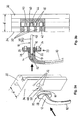
- a driver pin 18 is formed as a square and has at its lower end 48 a pin 19, on which a narrow end 56 of a Spring 52 is stuck. The opposite end 54 is widened so that it can be clamped in the square hole 14. This spring design also acts as a fall-out and transport safety.
- the driving pin 18 has at a distance t from its (in Fig. 1 to 2b) upper end 58 a point 36, where at least one notch 50, punching or the like. is arranged on an edge 38 and 39, respectively.
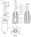
- Fig. 3a to Fig. 5b show how the assembly of a handle 10 which is axially fixed / rotatably mounted on a rosette 20, on a frame profile 30 is going on.
- the latter is provided with holes 32 in a predetermined hole pattern (Fig. 3a), which is adapted to the shape of the rosette 20.
- This has in the middle a bearing bushing 22 (FIG. 3 b) and, with respect to the abutment surface 34 of the profile 30, with screw holes 26 provided with cam 24, which can be covered by a pivotable cover plate 28.
- the one end 48 of the driving pin 18 is to be inserted into the central bore 32 of the frame profile 30, wherein the cams 24 engage in the external bores 32 of the profile 30 (FIGS. 4b, 5b) and then with screws 27 (FIG. 5b). be determined.
- the anchoring takes place in threaded holes 43 of a gear insert 42, which holds a gearbox 40. This is provided with a recess 44 (Fig. 3b) which receives the one end 48 of the driving pin 18 in a form-fitting manner.
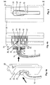
- FIG. 6 to 7b show a modified design, in which the driver pin 18 is received with its one end 48 in a Reduzierhülse 60 which is fitted snugly into the square hole 14, wherein a flange 62 on the collar 15 of the handle neck 12th supported. Between the Reduzierhülse 60 and the driving pin 18th There is a sliding friction fit such that in the pre-assembled state (Fig. 7) further protruding pin 18 can be driven by force with its inner end 48 deeper into the square hole 14 (Fig. 7b).
- the reducing sleeve 60 is expediently provided on the inside with projections (indicated in FIG. 7a) which bring about an elastically yielding inhibition of the nevertheless possible sliding movement.
- the driving pin 18 need not be integral; it may be composed of two opposite halves, provided that notches 50 are present only at the defined point 36 of the longitudinal edges 38, 39. Also come other springs 52 as drawn into consideration. In the alternative design without axial spring in the Reduzierhülse 60 inwardly directed projections as elastic barbs, ribs or the like. be formed, the e.g. cooperate with a transverse corrugation of a Mitauerux-end 48 latching.
- a driver connection according to the invention for window and door fittings has a stop body 20 having a bearing bush 22 for the neck 12 of a handle 10 and on a stop surface 34 of a window frame 30 and a door in the amount of an internal gear 38 or nut so can be mounted, that a square 18 slidably seated with one end 48 in a square hole 14 of the handle neck 12 and engages positively when plugging into the bearing bush 22 with its other end 58 in a gegen Dermat recess 44 of the nut 40, wherein at least one notch 50, punched or the like. can be locked on the nut 40.
- the driving pin 18 has irrespective of the frame or door thickness d an invariable length l.
- At least one notch 50, punching or the like. is at an edge 38; 39 of the driving pin 18 and latched to a Nußbegrenzungswand 46, in particular at its edge.
- the driving pin 18 is seated in a preferred embodiment in the square hole 14 under axial pressure of a spring 52, especially a coil spring which is clamped therein with a wide end 54 and expediently clamped with a narrow end 56 on a pin 19 of the driving pin 18.
- the latter can be arranged frictionally, namely slidably in a Reduzierhülse 60, which sits in the square hole 14 of the neck 12 under interference fit and axially supported on the frontal collar 15 with a flange 62.
- the inner contour of the existing example of plastic Reduzierhülse 60 is matched to the cross section of the driving pin 18 such that it is displaced by force, to which the sleeve 60 may have inwardly directed elastic projections.
Landscapes
- Engineering & Computer Science (AREA)
- Mechanical Engineering (AREA)
- Mechanical Coupling Of Light Guides (AREA)
- Use Of Switch Circuits For Exchanges And Methods Of Control Of Multiplex Exchanges (AREA)
- Amplifiers (AREA)
- Snaps, Bayonet Connections, Set Pins, And Snap Rings (AREA)
- Handcart (AREA)
- Wire Bonding (AREA)
- Hinges (AREA)
- Lock And Its Accessories (AREA)
Description
- Die Erfindung bezieht sich auf eine Mitnehmerverbindung gemäß dem Oberbegriff von Anspruch 1.
- Derartige Verbindungen werden vor allem für Fenster- und Türbeschläge gebraucht, wobei generell das Problem besteht, daß die Rahmen- bzw. Türstärke ganz unterschiedlich vorgegeben sein kann. Um dem zu begegnen, ist beispielsweise in DE-U1-1 705 743 ein Drückerstift oder Dorn beschrieben, der mit einem Drückergriff fest verbunden wird. Ein Ausgleich von Türstärken-Abweichungen soll mit einer längs in den Dorn/Drückerstift eingelassenen Schraubenfeder möglich sein, die durch seitliche Schlitze darin zugänglich ist. Zum Festlegen eines Gegengriffs wird ein Haltestift quer durch den Griffhals und durch die Feder hindurchgetrieben, deren Windungen so dicht beieinander liegen sollen, daß der Haltestift sich festkeilt. Weil dieser aber mit seinen Enden stets sichtbar ist und eventuell übersteht, ist das keine ästhetisch befriedigende Lösung; auch ist eine Verletzungsgefahr nicht auszuschließen. Außerdem erfordert die Montage größeren Aufwand, und es hängt von der Feder-Bemessung ab, ob der Haltestift überhaupt eintreibbar ist und dann auch seine Funktion entfaltet.
- DE-C2-197 07 836 offenbart ebenfalls eine Drückerverbindung mit einem eine Schloßnuß durchgreifenden Dorn, der als Vierkantstift ausgebildet ist. Er ist fest mit dem Hals eines ersten Türgriffs verbunden und trägt an seinem anderen Ende, einem zweiten Türgriff zugewandt, eine mit dem Mitnehmerstift bzw. Dorn verstiftete Außenhülse. In dem mit einer Innenhülse versehenen Hals des zweiten Griffs befindet sich ein federbelasteter Bajonettverschluß, der jedoch keinen Dornlängen-Ausgleich ermöglicht.
- Allgemein wird ein Beschlag mit einem Anschlagkörper, z.B. einer Rosette, auf der Außenseite bzw. Profiloberseite eines Fensters bzw. einer Tür in Höhe einer innenliegenden Getriebe- oder Schloßnuß montiert. Die Anordnung der dazu erforderlichen Befestigungslöcher ist in Bezug auf die Lage eines Vierkants genormt, der die Nuß als Mitnehmer durchsetzt. Unterschiedliche Fensterprofile bzw. Türstärken bedingen aber ungleiche Axialabstände der Nuß von der Anschlagfläche. Die herkömmlichen Vorrichtungen tragen nun nichts dazu bei, das sogenannte Vorstehmaß des Dorns oder Vierkantstifts bei verschiedenen Rahmen- oder Türstärken gleichgroß zu halten, um stets den Eingriff in eine Getriebe- oder Schloßnuß zu sichern. Infolgedessen ist man bislang gezwungen, eine Vielzahl unterschiedlicher Dorn- bzw. Stiftlängen zu fertigen und zu lagern, was erheblichen logistischen Aufwand bedeutet.
- Daher besteht ein Bedürfnis, die erwähnten und weitere Nachteile des Standes der Technik zu überwinden. Die Erfindung strebt an, mit möglichst einfachen Mitteln eine Anpassung der wirksamen Dorn- oder Stiftlänge an die gegebenen Fenster bzw. Türen eines Objekts zu erreichen. Dabei soll die volle Funktionsfähigkeit des Beschlages dauerhaft gewährleistet sein.
- Hauptmerkmale der Erfindung sind in Anspruch 1 angegeben. Ausgestaltungen sind Gegenstand der Ansprüche 2 bis 14.
- Bei einer Mitnehmerverbindung für Fenster- und Türbeschläge mit einem Anschlagkörper, z.B. einer Rosette, der eine Lagerbuchse für den Hals eines Griffs aufweist und an einer Anschlagfläche eines Fensters bzw. einer Tür in Höhe einer innenliegenden Getriebe- oder Schloßnuß so montierbar ist, daß ein als Vierkant ausgebildeter, mit einem Ende in einem Vierkantloch des Griffhalses sitzender Mitnehmerstift beim Einstecken in die Lagerbuchse mit seinem anderen Ende formschlüssig in eine gegengleiche Aussparung der Nuß eingreift, sieht die Erfindung gemäß Anspruch 1 vor, daß in dem Griffhals-Vierkantloch das eine Ende des Mitnehmerstifts verschieblich eingesetzt ist, daß das andere Mitnehmerstift-Ende an einer Stelle, die der maximalen Tiefe bis zur Nuß entspricht, wenigstens eine Kerbe, Ausstanzung o.dgl. aufweist und daß letztere an der Nuß verrastbar ist. Unabhängig von unterschiedlichen Rahmen- bzw. Türdicken erfolgt die Axialfestlegung des Mitnehmerstifts daher durch die Kerbe, Ausstanzung o.dgl. stets im exakt richtigen Abstand an der Getriebe- bzw. Schloßnuß-Aussparung.
- Ein wichtiges Merkmal besteht darin, daß der Mitnehmerstift unabhängig von der Dicke bzw. Stärke des jeweiligen Fensterrahmens bzw. der jeweiligen Tür eine unveränderliche Länge hat. Damit ist bezüglich Fertigung und Lagerhaltung ein entscheidender Fortschritt erzielt.
- Die Kerbe, Ausstanzung o.dgl. ist vorteilhaft an einer Kante des Mitnehmerstifts angeordnet, so daß eine markante Rastung an der Nuß erfolgt. Noch besser ist es, wenn wenigstens zwei Kerben, Ausstanzungen o.dgl. an benachbarten Kanten des Mitnehmerstifts vorhanden sind, was das zuverlässige Verrasten erleichtert, vor allem wenn die bzw. jede Kerbe, Ausstanzung o.dgl. am Rand einer Nußbegrenzungswand verrastbar ist.
- Eine bedeutsame Ausgestaltung der Erfindung besteht darin, daß der Mitnehmerstift unter Zwischenlage einer Feder im Vierkantloch sitzt. Die Feder kann eine Druckfeder sein, namentlich eine Schraubenfeder. Sie bewirkt, daß der Mitnehmerstift fortwährend unter axialer Federkraft zu der Getriebe- bzw. Schloßnuß hin gedrückt wird und in sie stets ausreichend hineinragt.
- Zwar ist aus DE-U1-94 15 966 bei einem Verschlußgetriebe ein Betätigungshebel ersichtlich, in dessen Hals eine Druckfeder sitzt, die ein mit Kugel-Enden versehenes Kupplungsstück axial belastet, so daß bei der Montage ein seitlicher Achsversatz zu einer Schloßnuß hin ausgeglichen werden kann. Ein axialer Längenausgleich für unterschiedliche Rahmen- oder Türstärken ist aber nicht vorgesehen. Das gilt auch für die in DE-C-35 322 vorgeschlagene Konstruktion einer lösbaren Türschloß-Verbindung, die zwei Griffknöpfe hat. Eine Druckfeder verspannt hierbei einen abschnittsweise mit Vierkantprofil versehenen, sonst runden Stift in dem einen Griffknopf, aber ohne daß ein Vorstehmaß einzuhalten wäre. Und auch bei einem mehrkantigen Wechselschloßstift nach DE-C2-28 31 514, wobei eine Schloßnuß durch ein Anschlag-Endstück hintergriffen wird, ist zwar zwischen der Nuß und dem Griffhals-Ende eine Schraubenfeder angeordnet. Sie dient aber bloß zum Ausgleich von Toleranzen der Schloßnußdicke und nicht zur variablen Längenänderung des Vierkantstifts. Die Erfindung geht über den vorgenannten Stand der Technik deutlich hinaus.
- Mit Vorteil weist die Feder ein weites Ende auf, das im Vierkantloch verklemmbar ist, so daß ihre Funktion auf einfache Weise gesichert wird. Das andere Ende kann so eng gestaltet sein, daß es auf einem Zapfen des Mitnehmerstifts klemmt und mithin stets zuverlässig gehalten ist, was positiv zur Funktionstüchtigkeit der Verbindung beiträgt.
- Bei einer anderen Bauform ist vorgesehen, daß der Mitnehmerstift unter Zwischenlage einer Reduzierhülse reibschlüssig verschieblich im Vierkantloch sitzt. Die Hülse ist in den Griffhals satt eingepaßt und stützt sich an dessen stirnseitigem Bund mit einem Flansch axial ab. Die Innenkontur der Reduzierhülse ist auf den Querschnitt des Mitnehmerstifts so abgestimmt, daß dieser bei Krafteinwirkung verschiebbar ist. Elastische Vorsprünge, die ins Hülsen-Innere ragen, stellen eine gewisse Gleithemmung und auch genügende Leichtgängigkeit sicher. Vorteilhaft ist die Reduzierhülse ein präzise dimensioniertes Spritzgußteil, das sich leicht montieren läßt und die verlangte Verschieblichkeit des Mitnehmerstifts dauerhaft leistet.
- Weitere Merkmale, Einzelheiten und Vorteile der Erfindung ergeben sich aus dem Wortlaut der Ansprüche sowie aus der folgenden Beschreibung von Ausführungsbeispielen anhand der Zeichnungen. Darin zeigen:
- Fig. 1
- eine auseinandergezogene Ansicht der Bestandteile einer Griff-Mitnehmerstift-Anordnung,
- Fig. 2
- eine Schnittansicht entsprechend der Linie II-II in Fig. 2a im vormontierten Zustand,
- Fig. 2a
- eine Stirnansicht der Anordnung von Fig. 2 bzw. Fig. 2b,
- Fig. 2b
- eine Schnittansicht entsprechend Fig. 2 im montierten Zustand,
- Fig. 3a
- eine Schrägansicht eines Griffs mit vormontiertem Mitnehmerstift im Abstand zu einem Rahmenprofil,
- Fig. 3b
- eine Seitenansicht, teilweise im Schnitt entsprechend der Linie III-III in Fig. 3,
- Fig. 4a
- eine Schrägansicht ähnlich Fig. 3a, jedoch im teilmontierten Zustand,
- Fig. 4b
- eine Schnittansicht ähnlich Fig. 3b, jedoch im teilmontierten Zustand,
- Fig. 5a
- eine Schrägansicht ähnlich Fig. 3a bzw. 4a, jedoch im fertig montierten Zustand,
- Fig. 5b
- eine Schnittansicht ähnlich Fig. 3b bzw. 4b, jedoch im fertig montierten Zustand,
- Fig. 6
- eine auseinandergezogene Schrägansicht der Bestandteile einer abgewandelten Bauform einer Griff-Mitnehmerstift-Anordnung,
- Fig. 7
- eine Seitenansicht, teilweise im Schnitt entsprechend der Linie VII-VII von Fig. 7a,
- Fig. 7a
- eine Stirnansicht der Anordnung von Fig. 7 und
- Fig. 7b
- eine Schnittansicht ähnlich Fig. 7, jedoch im eingeschobenen Zustand des Mitnehmerstifts.
- Man erkennt in Fig. 1 bis Fig. 2b einen Griffhals 12 mit einem zentrisch angeordneten Vierkantloch 14 und einem stirnseitigen Bund 15. Ein Mitnehmerstift 18 ist als Vierkant ausgebildet und hat an seinem unteren Ende 48 einen Zapfen 19, auf dem ein enges Ende 56 einer Feder 52 klemmt. Deren entgegengesetztes Ende 54 ist aufgeweitet, so daß es im Vierkantloch 14 verklemmbar ist. Diese Federgestaltung wirkt zugleich als Herausfall- und Transportsicherung. Der Mitnehmerstift 18 hat in einem Abstand t von seinem (in Fig. 1 bis 2b) oberen Ende 58 eine Stelle 36, wo wenigstens eine Kerbe 50, Ausstanzung o.dgl. an einer Kante 38 bzw. 39 angeordnet ist.
- Fig. 3a bis Fig. 5b zeigen, wie die Montage eines Griffes 10 der an einer Rosette 20 axialfest/drehbar angebracht ist, an einem Rahmenprofil 30 vor sich geht. Letzteres ist mit Bohrungen 32 in vorgegebenem Lochbild (Fig. 3a) versehen, das auf die Formgebung der Rosette 20 abgestimmt ist. Diese hat mittig eine Lagerbuchse 22 (Fig. 3b) und, gegenüber der Anschlagfläche 34 des Profils 30, mit Schraublöchern 26 versehene Nocken 24, die von einer schwenkbaren Abdeckplatte 28 verdeckbar sind.
- Man sieht, daß das eine Ende 48 des Mitnehmerstifts 18 in die Mittelbohrung 32 des Rahmenprofils 30 einzusetzen ist, wobei die Nocken 24 in die Außenbohrungen 32 des Profils 30 eingreifen (Fig. 4b, 5b) und dann mit Schrauben 27 (Fig. 5b) festgelegt werden. Die Verankerung erfolgt in Gewindelöchern 43 eines Getriebe-Einsatzes 42, der eine Getriebenuß 40 haltert. Diese ist mit einer Aussparung 44 (Fig. 3b) versehen, die das eine Ende 48 des Mitnehmerstifts 18 formschlüssig aufnimmt.
- Im vormontierten Zustand (Fig. 3b) ist die Feder 52 entspannt. Wird nun das ihr gegenüberliegende Ende 48 des Vierkantstifts 18 in die Aussparung 44 der Nuß 40 eingeführt (Fig. 4b), so verrastet die bzw. jede Kerbe 50 an der ihr benachbarten Nußbegrenzungswand 46. Damit ist der Eingriff des Endes 48 des Mitnehmerstifts 18 in der erforderlichen Nußtiefe t gewährleistet. Wird nun die Rosette 20 fest angeschlagen, indem ihre Nocken 24 in die Bohrungen 32 eingetrieben und mittels der Schrauben 27 befestigt werden, so schiebt sich das andere Ende 58 im Vierkantloch 14 tiefer hinein, wobei die Feder 52 zusammengepreßt wird (Fig. 5b). Dies bewirkt einen konstanten Andruck des Mitnehmerstifts 18 in die Nuß 40 hinein.
- Fig. 6 bis Fig. 7b zeigen eine abgewandelte Bauform, bei welcher der Mitnehmerstift 18 mit seinem einen Ende 48 in einer Reduzierhülse 60 aufgenommen wird, die in das Vierkantloch 14 satt eingepaßt ist, wobei ein Flansch 62 sich auf dem Bund 15 des Griffhalses 12 abstützt. Zwischen der Reduzierhülse 60 und dem Mitnehmerstift 18 besteht eine Gleit-Reib-Passung derart, daß der im vormontierten Zustand (Fig. 7) weiter herausragende Stift 18 bei Krafteinwirkung mit seinem inneren Ende 48 tiefer in das Vierkantloch 14 hineingetrieben werden kann (Fig. 7b). Dazu ist die Reduzierhülse 60 innen zweckmäßig mit (in Fig. 7a angedeuteten) Vorsprüngen versehen, die eine elastisch-nachgiebige Hemmung der dennoch möglichen Gleitbewegung bewirken.
- Die Erfindung ist nicht auf eine der vorbeschriebenen Ausführungsformen beschränkt, sondern vielfältig abwandelbar. Beispielsweise muß der Mitnehmerstift 18 nicht einstückig sein; er kann aus zwei gegengleichen Hälften zusammengesetzt sein, soferne nur an der definierten Stelle 36 der Längskanten 38, 39 jeweils Kerben 50 vorhanden sind. Auch kommen andere Federn 52 als gezeichnet in Betracht. Bei der Alternativ-Bauform ohne Axialfeder können die in der Reduzierhülse 60 nach innen gerichteten Vorsprünge als elastische Widerhaken, Rippen o.dgl. ausgebildet sein, die z.B. mit einer Quer-Riffelung des einen Mitnehmerstift-Endes 48 rastend zusammenwirken.
- Festzuhalten ist, daß eine erfindungsgemäße Mitnehmerverbindung für Fenster- und Türbeschläge einen Anschlagkörper 20 hat, der eine Lagerbuchse 22 für den Hals 12 eines Griffs 10 aufweist und an einer Anschlagfläche 34 eines Fensterrahmens 30 bzw. einer Tür in Höhe einer innenliegenden Getriebenuß 38 oder Schloßnuß so montierbar ist, daß ein Vierkant 18 mit einem Ende 48 in einem Vierkantloch 14 des Griffhalses 12 verschieblich sitzt und beim Einstecken in die Lagerbuchse 22 mit seinem anderen Ende 58 formschlüssig in eine gegengleiche Aussparung 44 der Nuß 40 eingreift, wobei wenigstens eine Kerbe 50, Ausstanzung o.dgl. an der Nuß 40 verrastbar ist. Der Mitnehmerstift 18 hat unabhängig von der Rahmen- bzw. Türstärke d eine unveränderliche Länge ℓ. Wenigstens eine Kerbe 50, Ausstanzung o.dgl. ist an einer Kante 38; 39 des Mitnehmerstift 18 angeordnet und an einer Nußbegrenzungswand 46 verrastbar, insbesondere an deren Rand. Der Mitnehmerstift 18 sitzt bei einer bevorzugten Ausführungsform im Vierkantloch 14 unter Axialdruck einer Feder 52, speziell einer Schraubenfeder, die darin mit einem weiten Ende 54 verklemmbar ist und zweckmäßig mit einem engen Ende 56 auf einem Zapfen 19 des Mitnehmerstifts 18 klemmt. Alternativ kann letzterer reibschlüssig angeordnet sein, und zwar verschieblich in einer Reduzierhülse 60, die im Vierkantloch 14 des Halses 12 unter Preßpassung sitzt und sich an dessen stirnseitigem Bund 15 mit einem Flansch 62 axial abstützt. Die Innenkontur der z.B. aus Kunststoff bestehenden Reduzierhülse 60 ist auf den Querschnitt des Mitnehmerstifts 18 derart abgestimmt, daß dieser bei Krafteinwirkung verschiebbar ist, wozu die Hülse 60 nach innen gerichtete elastische Vorsprünge haben kann.
- Sämtliche aus den Ansprüchen, der Beschreibung und der Zeichnung hervorgehenden Merkmale und Vorteile, einschließlich konstruktiver Einzelheiten und räumlicher Anordnungen, können sowohl für sich als auch in den verschiedensten Kombinationen erfindungswesentlich sein.
-
- d
- Dicke / Stärke
- ℓ
- Länge
- t
- Nußtiefe
- 10
- Griff
- 12
- Griffhals
- 14
- Vierkantloch
- 15
- Bund
- 16
- Bördelbuchse
- 18
- Mitnehmerstift / Vierkant
- 19
- Zapfen
- 20
- Rosette
- 22
- Lagerbuchse
- 24
- Nocken
- 26
- Schraublöcher
- 27
- Schrauben
- 28
- Abdeckplatte
- 30
- Rahmenprofil
- 32
- Lochbild / Bohrungen
- 34
- Anschlagfläche
- 36
- Stelle (an 18 / 58)
- 38
- Kante
- 39
- Kante
- 40
- (Getriebe-)Nuß
- 42
- Getriebe-Einsatz
- 43
- Gewindelöcher
- 44
- Aussparung / Vierkantloch
- 46
- Nußbegrenzungswand
- 48
- eines Ende (von 18)
- 50
- Kerbe
- 52
- Feder
- 54
- weites Federende
- 56
- enges Federende
- 58
- anderes Ende (von 18)
- 60
- Reduzierhülse
- 62
- Flansch
Claims (14)
- Mitnehmerverbindung für Fenster- und Türbeschläge mit einem Anschlagkörper, z.B. einer Rosette (20), der eine Lagerbuchse (22) für den Hals (12) eines Griffs (10) aufweist und an einer Anschlagfläche (34) eines Fensterrahmens (30) bzw. einer Tür in Höhe einer innenliegenden Getriebenuß (38) oder Schloßnuß so montierbar ist, daß ein als Vierkant ausgebildeter, mit einem Ende (48) in einem Vierkantloch (14) des Griffhalses (12) sitzender Mitnehmerstift (18) beim Einstecken in die Lagerbuchse (22) mit seinem anderen Ende (58) formschlüssig in eine gegengleiche Aussparung (44) der Nuß (40) eingreift,
dadurch gekennzeichnet,• daß in dem Griffhals-Vierkantloch (14) das eine Ende (48) des Mitnehmerstifts (18) verschieblich eingesetzt ist,• daß das andere Mitnehmerstift-Ende (58) an einer Stelle (36), die der maximalenTiefe (t) bis zur Nuß (40) entspricht, wenigstens eine Kerbe (50), Ausstanzung o.dgl. aufweist und• daß letztere (50) an der Nuß (40) verrastbar ist. - Mitnehmerverbindung nach Anspruch 1, dadurch gekennzeichnet,
daß der Mitnehmerstift (18) unabhängig von der Dicke bzw. Stärke des jeweiligen Fensterrahmens (30) bzw. der jeweiligen Tür eine unveränderliche Länge (ℓ) hat. - Mitnehmerverbindung nach Anspruch 1 oder 2, dadurch gekennzeichnet, daß die Kerbe (50), Ausstanzung o.dgl. an einer Kante (38) des Mitnehmerstifts (18) angeordnet ist.
- Mitnehmerverbindung nach einem der Ansprüche 1 bis 3, dadurch gekennzeichnet, daß wenigstens zwei Kerben (50), Ausstanzungen o.dgl. insbesondere an benachbarten Kanten (38, 39) des Mitnehmerstifts (18) vorhanden sind.
- Mitnehmerverbindung nach einem der Ansprüche 1 bis 4, dadurch gekennzeichnet, daß die bzw. jede Kerbe (50), Ausstanzung o.dgl. an einer Nußbegrenzungswand (46) verrastbar ist, namentlich an deren Rand.
- Mitnehmerverbindung nach einem der Ansprüche 1 bis 5, dadurch gekennzeichnet, daß der Mitnehmerstift (18) unter Zwischenlage einer Feder (52) im Vierkantloch (14) sitzt.
- Mitnehmerverbindung nach Anspruch 6, dadurch gekennzeichnet,
daß die Feder (52) eine Druckfeder ist, vorzugsweise eine Schraubenfeder. - Mitnehmerverbindung nach Anspruch 6 oder 7, dadurch gekennzeichnet, daß die Feder (52) ein weites Ende (54) aufweist, das im Vierkantloch (14) verklemmbar ist.
- Mitnehmerverbindung nach einem der Ansprüche 6 bis 8, dadurch gekennzeichnet, daß die Feder (52) ein enges Ende (56) aufweist, das auf einem Zapfen (19) des Mitnehmerstifts (18) verklemmbar ist.
- Mitnehmerverbindung nach einem der Ansprüche 1 bis 5, dadurch gekennzeichnet, daß der Mitnehmerstift (18) unter Zwischenlage einer Reduzierhülse (60) reibschlüssig verschieblich im Vierkantloch (14) sitzt.
- Mitnehmerverbindung nach Anspruch 10, dadurch gekennzeichnet, daß die Reduzierhülse (60) in den Griffhals (12) satt eingepaßt ist und sich an dessen stirnseitigem Bund mit einem Flansch (62) axial abstützt.
- Mitnehmerverbindung nach Anspruch 10 oder 11, dadurch gekennzeichnet, daß die Innenkontur der Reduzierhülse (60) auf den Querschnitt des Mitnehmerstifts (18) derart abgestimmt ist, daß dieser bei Krafteinwirkung verschiebbar ist.
- Mitnehmerverbindung nach einem der Ansprüche 10 bis 12, dadurch gekennzeichnet, daß die Reduzierhülse (60) nach innen gerichtete, insbesondere elastische Vorsprünge aufweist.
- Mitnehmerverbindung nach einem der Ansprüche 10 bis 13, dadurch gekennzeichnet, daß die Reduzierhülse (60) ein Kunststoff-Spritzgußteil ist.
Priority Applications (1)
| Application Number | Priority Date | Filing Date | Title |
|---|---|---|---|
| SI200430113T SI1553246T1 (sl) | 2003-12-23 | 2004-12-04 | Sojemalna povezava |
Applications Claiming Priority (2)
| Application Number | Priority Date | Filing Date | Title |
|---|---|---|---|
| ITMI20030612U | 2003-12-23 | ||
| IT000612U ITMI20030612U1 (it) | 2003-12-23 | 2003-12-23 | Collegamento a trascinamento |
Publications (2)
| Publication Number | Publication Date |
|---|---|
| EP1553246A1 EP1553246A1 (de) | 2005-07-13 |
| EP1553246B1 true EP1553246B1 (de) | 2006-09-06 |
Family
ID=34586985
Family Applications (1)
| Application Number | Title | Priority Date | Filing Date |
|---|---|---|---|
| EP04028783A Expired - Lifetime EP1553246B1 (de) | 2003-12-23 | 2004-12-04 | Mitnehmerverbindung |
Country Status (7)
| Country | Link |
|---|---|
| EP (1) | EP1553246B1 (de) |
| AT (1) | ATE338864T1 (de) |
| DE (1) | DE502004001406D1 (de) |
| DK (1) | DK1553246T3 (de) |
| ES (1) | ES2273147T3 (de) |
| IT (1) | ITMI20030612U1 (de) |
| SI (1) | SI1553246T1 (de) |
Cited By (1)
| Publication number | Priority date | Publication date | Assignee | Title |
|---|---|---|---|---|
| WO2020254000A1 (de) | 2019-05-20 | 2020-12-24 | Siegenia-Aubi Kg | Fenster oder türbeschlag |
Families Citing this family (5)
| Publication number | Priority date | Publication date | Assignee | Title |
|---|---|---|---|---|
| DE202008004508U1 (de) | 2008-04-01 | 2009-08-13 | Hoppe Ag | Secustic-Vierkant (Beschlag für Fenster oder Türen) |
| DE102014102003A1 (de) * | 2014-02-18 | 2015-08-20 | Dorma Deutschland Gmbh | Schloss mit einer Schlossnuss zur Aufnahme einer Reduzierhülse |
| ES2980441T3 (es) * | 2020-11-12 | 2024-10-01 | Hoppe Ag | Manija de accionamiento con elemento de arrastre de longitud variable |
| DE102021102245B4 (de) * | 2021-02-01 | 2022-10-20 | Rahrbach Gmbh | Betätigungsbaugruppe zur Betätigung eines Drückerstifts |
| PL446235A1 (pl) * | 2023-09-25 | 2025-03-31 | Fks Okucia Okienne I Drzwiowe Spółka Z Ograniczoną Odpowiedzialnością | Zespół klamki okiennej |
Family Cites Families (3)
| Publication number | Priority date | Publication date | Assignee | Title |
|---|---|---|---|---|
| BE475884A (de) * | ||||
| US2478589A (en) * | 1945-08-22 | 1949-08-09 | Connector Locks America Inc | Lock handle assembly |
| DE19707836C2 (de) * | 1997-02-27 | 2001-05-10 | Dorma Gmbh & Co Kg | Drückerverbindung an Griffen für Türen oder dergleichen |
-
2003
- 2003-12-23 IT IT000612U patent/ITMI20030612U1/it unknown
-
2004
- 2004-12-04 AT AT04028783T patent/ATE338864T1/de not_active IP Right Cessation
- 2004-12-04 ES ES04028783T patent/ES2273147T3/es not_active Expired - Lifetime
- 2004-12-04 SI SI200430113T patent/SI1553246T1/sl unknown
- 2004-12-04 DK DK04028783T patent/DK1553246T3/da active
- 2004-12-04 EP EP04028783A patent/EP1553246B1/de not_active Expired - Lifetime
- 2004-12-04 DE DE502004001406T patent/DE502004001406D1/de not_active Expired - Fee Related
Cited By (1)
| Publication number | Priority date | Publication date | Assignee | Title |
|---|---|---|---|---|
| WO2020254000A1 (de) | 2019-05-20 | 2020-12-24 | Siegenia-Aubi Kg | Fenster oder türbeschlag |
Also Published As
| Publication number | Publication date |
|---|---|
| SI1553246T1 (sl) | 2007-04-30 |
| ATE338864T1 (de) | 2006-09-15 |
| EP1553246A1 (de) | 2005-07-13 |
| DE502004001406D1 (de) | 2006-10-19 |
| ITMI20030612U1 (it) | 2005-06-24 |
| DK1553246T3 (da) | 2007-01-15 |
| ES2273147T3 (es) | 2007-05-01 |
Similar Documents
| Publication | Publication Date | Title |
|---|---|---|
| EP2193246B1 (de) | Betätigungshandhabenpaar für eine tür | |
| EP0440986B1 (de) | Treibstangengetriebe | |
| CH700306A1 (de) | Verriegelungseinrichtung. | |
| EP1978187B1 (de) | Beschlaganordnung für ein Fenster, eine Tür oder dergleichen | |
| WO2008022664A1 (de) | Griffschale zum einklipsen in einem durchbruch in einer dünnen wand | |
| EP2476823A2 (de) | Betätigungshandhabe | |
| DE9212950U1 (de) | Treibstangenbeschlag für Fenster, Türen o.dgl. | |
| DE2313690A1 (de) | Treibstangenbeschlag fuer fenster, tueren od.dgl | |
| EP1072745B1 (de) | Beschlag für die Verriegelung von Fenstern oder Türen | |
| EP0440987B2 (de) | Treibstangengetriebe | |
| EP1553246B1 (de) | Mitnehmerverbindung | |
| EP0892138B1 (de) | Stulpschienenbeschlag für eine Tür oder ein Fenster | |
| EP3798395B1 (de) | Verschlusszapfen | |
| EP2602412B1 (de) | Beschlaganordnung | |
| EP2078812A2 (de) | Abdeckelement für eine Gleitschiene | |
| DE10229449C5 (de) | Verriegelungsbeschlag eines Flügels, der zu seiner Befestigung mit versetzten inneren und äußeren Abstützmitteln versehen ist | |
| DE19737538C2 (de) | Befestigungseinrichtung | |
| EP1091065A2 (de) | Schliesseinrichtung für einen Beschlag zur Verriegelung eines beweglichen Rahmenteils eines Fensters oder einer Tür | |
| EP0733749A1 (de) | Betätigungsvorrichtung für eine Ablaufarmatur eines Spülkastens | |
| EP0855486B1 (de) | Zentralverriegelungsstellelement für Türen oder Klappen von Kraftfahrzeugen | |
| EP1321605B1 (de) | Betätigungshandhabe | |
| EP1048803A2 (de) | Schliessvorrichtung zum Einsatz in ein Schloss mit einer beidseitig offenen Einstecköffnung | |
| DE8910095U1 (de) | Betätigungsvorrichtung für einen Riegel eines Schlosses | |
| DE29800735U1 (de) | Betätigungshandhabe | |
| DE19516848A1 (de) | Schließzylinder, insbesondere für Kraftfahrzeug-Türschlösser |
Legal Events
| Date | Code | Title | Description |
|---|---|---|---|
| PUAI | Public reference made under article 153(3) epc to a published international application that has entered the european phase |
Free format text: ORIGINAL CODE: 0009012 |
|
| AK | Designated contracting states |
Kind code of ref document: A1 Designated state(s): AT BE BG CH CY CZ DE DK EE ES FI FR GB GR HU IE IS IT LI LT LU MC NL PL PT RO SE SI SK TR |
|
| AX | Request for extension of the european patent |
Extension state: AL BA HR LV MK YU |
|
| 17P | Request for examination filed |
Effective date: 20050528 |
|
| GRAP | Despatch of communication of intention to grant a patent |
Free format text: ORIGINAL CODE: EPIDOSNIGR1 |
|
| AKX | Designation fees paid |
Designated state(s): AT BE BG CH CY CZ DE DK EE ES FI FR GB GR HU IE IS IT LI LT LU MC NL PL PT RO SE SI SK TR |
|
| GRAA | (expected) grant |
Free format text: ORIGINAL CODE: 0009210 |
|
| GRAS | Grant fee paid |
Free format text: ORIGINAL CODE: EPIDOSNIGR3 |
|
| AK | Designated contracting states |
Kind code of ref document: B1 Designated state(s): AT BE BG CH CY CZ DE DK EE ES FI FR GB GR HU IE IS IT LI LT LU MC NL PL PT RO SE SI SK TR |
|
| PG25 | Lapsed in a contracting state [announced via postgrant information from national office to epo] |
Ref country code: RO Free format text: LAPSE BECAUSE OF FAILURE TO SUBMIT A TRANSLATION OF THE DESCRIPTION OR TO PAY THE FEE WITHIN THE PRESCRIBED TIME-LIMIT Effective date: 20060906 Ref country code: LT Free format text: LAPSE BECAUSE OF FAILURE TO SUBMIT A TRANSLATION OF THE DESCRIPTION OR TO PAY THE FEE WITHIN THE PRESCRIBED TIME-LIMIT Effective date: 20060906 Ref country code: IE Free format text: LAPSE BECAUSE OF FAILURE TO SUBMIT A TRANSLATION OF THE DESCRIPTION OR TO PAY THE FEE WITHIN THE PRESCRIBED TIME-LIMIT Effective date: 20060906 |
|
| REG | Reference to a national code |
Ref country code: GB Ref legal event code: FG4D Free format text: NOT ENGLISH |
|
| REG | Reference to a national code |
Ref country code: CH Ref legal event code: EP |
|
| REG | Reference to a national code |
Ref country code: IE Ref legal event code: FG4D Free format text: LANGUAGE OF EP DOCUMENT: GERMAN |
|
| REF | Corresponds to: |
Ref document number: 502004001406 Country of ref document: DE Date of ref document: 20061019 Kind code of ref document: P |
|
| PGFP | Annual fee paid to national office [announced via postgrant information from national office to epo] |
Ref country code: TR Payment date: 20061124 Year of fee payment: 3 |
|
| PGFP | Annual fee paid to national office [announced via postgrant information from national office to epo] |
Ref country code: SI Payment date: 20061129 Year of fee payment: 3 |
|
| PGFP | Annual fee paid to national office [announced via postgrant information from national office to epo] |
Ref country code: CZ Payment date: 20061201 Year of fee payment: 3 Ref country code: SK Payment date: 20061201 Year of fee payment: 3 |
|
| GBT | Gb: translation of ep patent filed (gb section 77(6)(a)/1977) |
Effective date: 20061115 |
|
| PG25 | Lapsed in a contracting state [announced via postgrant information from national office to epo] |
Ref country code: SE Free format text: LAPSE BECAUSE OF FAILURE TO SUBMIT A TRANSLATION OF THE DESCRIPTION OR TO PAY THE FEE WITHIN THE PRESCRIBED TIME-LIMIT Effective date: 20061206 Ref country code: BG Free format text: LAPSE BECAUSE OF FAILURE TO SUBMIT A TRANSLATION OF THE DESCRIPTION OR TO PAY THE FEE WITHIN THE PRESCRIBED TIME-LIMIT Effective date: 20061206 |
|
| PGFP | Annual fee paid to national office [announced via postgrant information from national office to epo] |
Ref country code: AT Payment date: 20061213 Year of fee payment: 3 Ref country code: DK Payment date: 20061213 Year of fee payment: 3 |
|
| PGFP | Annual fee paid to national office [announced via postgrant information from national office to epo] |
Ref country code: FI Payment date: 20061214 Year of fee payment: 3 |
|
| PGFP | Annual fee paid to national office [announced via postgrant information from national office to epo] |
Ref country code: LU Payment date: 20061215 Year of fee payment: 3 |
|
| PGFP | Annual fee paid to national office [announced via postgrant information from national office to epo] |
Ref country code: DE Payment date: 20061218 Year of fee payment: 3 |
|
| PGFP | Annual fee paid to national office [announced via postgrant information from national office to epo] |
Ref country code: ES Payment date: 20061228 Year of fee payment: 3 |
|
| REG | Reference to a national code |
Ref country code: CH Ref legal event code: NV Representative=s name: PA ALDO ROEMPLER |
|
| PG25 | Lapsed in a contracting state [announced via postgrant information from national office to epo] |
Ref country code: MC Free format text: LAPSE BECAUSE OF NON-PAYMENT OF DUE FEES Effective date: 20061231 |
|
| PG25 | Lapsed in a contracting state [announced via postgrant information from national office to epo] |
Ref country code: IS Free format text: LAPSE BECAUSE OF FAILURE TO SUBMIT A TRANSLATION OF THE DESCRIPTION OR TO PAY THE FEE WITHIN THE PRESCRIBED TIME-LIMIT Effective date: 20070106 |
|
| REG | Reference to a national code |
Ref country code: DK Ref legal event code: T3 |
|
| PGFP | Annual fee paid to national office [announced via postgrant information from national office to epo] |
Ref country code: BE Payment date: 20070118 Year of fee payment: 3 |
|
| PG25 | Lapsed in a contracting state [announced via postgrant information from national office to epo] |
Ref country code: PT Free format text: LAPSE BECAUSE OF FAILURE TO SUBMIT A TRANSLATION OF THE DESCRIPTION OR TO PAY THE FEE WITHIN THE PRESCRIBED TIME-LIMIT Effective date: 20070219 |
|
| ET | Fr: translation filed | ||
| REG | Reference to a national code |
Ref country code: IE Ref legal event code: FD4D |
|
| REG | Reference to a national code |
Ref country code: ES Ref legal event code: FG2A Ref document number: 2273147 Country of ref document: ES Kind code of ref document: T3 |
|
| PLBE | No opposition filed within time limit |
Free format text: ORIGINAL CODE: 0009261 |
|
| STAA | Information on the status of an ep patent application or granted ep patent |
Free format text: STATUS: NO OPPOSITION FILED WITHIN TIME LIMIT |
|
| 26N | No opposition filed |
Effective date: 20070607 |
|
| PG25 | Lapsed in a contracting state [announced via postgrant information from national office to epo] |
Ref country code: GR Free format text: LAPSE BECAUSE OF FAILURE TO SUBMIT A TRANSLATION OF THE DESCRIPTION OR TO PAY THE FEE WITHIN THE PRESCRIBED TIME-LIMIT Effective date: 20061207 |
|
| PGFP | Annual fee paid to national office [announced via postgrant information from national office to epo] |
Ref country code: FR Payment date: 20061212 Year of fee payment: 3 |
|
| BERE | Be: lapsed |
Owner name: *HOPPE A.G. Effective date: 20071231 |
|
| PG25 | Lapsed in a contracting state [announced via postgrant information from national office to epo] |
Ref country code: EE Free format text: LAPSE BECAUSE OF FAILURE TO SUBMIT A TRANSLATION OF THE DESCRIPTION OR TO PAY THE FEE WITHIN THE PRESCRIBED TIME-LIMIT Effective date: 20060906 |
|
| PG25 | Lapsed in a contracting state [announced via postgrant information from national office to epo] |
Ref country code: CZ Free format text: LAPSE BECAUSE OF NON-PAYMENT OF DUE FEES Effective date: 20071204 Ref country code: HU Free format text: LAPSE BECAUSE OF FAILURE TO SUBMIT A TRANSLATION OF THE DESCRIPTION OR TO PAY THE FEE WITHIN THE PRESCRIBED TIME-LIMIT Effective date: 20070307 Ref country code: FI Free format text: LAPSE BECAUSE OF NON-PAYMENT OF DUE FEES Effective date: 20071204 |
|
| REG | Reference to a national code |
Ref country code: DK Ref legal event code: EBP |
|
| PG25 | Lapsed in a contracting state [announced via postgrant information from national office to epo] |
Ref country code: AT Free format text: LAPSE BECAUSE OF NON-PAYMENT OF DUE FEES Effective date: 20071204 |
|
| REG | Reference to a national code |
Ref country code: CH Ref legal event code: PCAR Free format text: ALDO ROEMPLER PATENTANWALT;BRENDENWEG 11 POSTFACH 154;9424 RHEINECK (CH) |
|
| PG25 | Lapsed in a contracting state [announced via postgrant information from national office to epo] |
Ref country code: PL Free format text: LAPSE BECAUSE OF FAILURE TO SUBMIT A TRANSLATION OF THE DESCRIPTION OR TO PAY THE FEE WITHIN THE PRESCRIBED TIME-LIMIT Effective date: 20061204 Ref country code: BE Free format text: LAPSE BECAUSE OF NON-PAYMENT OF DUE FEES Effective date: 20071231 Ref country code: SI Free format text: LAPSE BECAUSE OF NON-PAYMENT OF DUE FEES Effective date: 20071205 |
|
| PG25 | Lapsed in a contracting state [announced via postgrant information from national office to epo] |
Ref country code: SK Free format text: LAPSE BECAUSE OF NON-PAYMENT OF DUE FEES Effective date: 20071204 Ref country code: DE Free format text: LAPSE BECAUSE OF NON-PAYMENT OF DUE FEES Effective date: 20080701 |
|
| REG | Reference to a national code |
Ref country code: SI Ref legal event code: KO00 Effective date: 20080819 |
|
| REG | Reference to a national code |
Ref country code: FR Ref legal event code: ST Effective date: 20081020 |
|
| PG25 | Lapsed in a contracting state [announced via postgrant information from national office to epo] |
Ref country code: CY Free format text: LAPSE BECAUSE OF FAILURE TO SUBMIT A TRANSLATION OF THE DESCRIPTION OR TO PAY THE FEE WITHIN THE PRESCRIBED TIME-LIMIT Effective date: 20060906 |
|
| PG25 | Lapsed in a contracting state [announced via postgrant information from national office to epo] |
Ref country code: DK Free format text: LAPSE BECAUSE OF NON-PAYMENT OF DUE FEES Effective date: 20080102 |
|
| REG | Reference to a national code |
Ref country code: ES Ref legal event code: FD2A Effective date: 20071205 |
|
| PG25 | Lapsed in a contracting state [announced via postgrant information from national office to epo] |
Ref country code: ES Free format text: LAPSE BECAUSE OF NON-PAYMENT OF DUE FEES Effective date: 20071205 Ref country code: FR Free format text: LAPSE BECAUSE OF NON-PAYMENT OF DUE FEES Effective date: 20071231 |
|
| REG | Reference to a national code |
Ref country code: CH Ref legal event code: PL |
|
| GBPC | Gb: european patent ceased through non-payment of renewal fee |
Effective date: 20081204 |
|
| PG25 | Lapsed in a contracting state [announced via postgrant information from national office to epo] |
Ref country code: LU Free format text: LAPSE BECAUSE OF NON-PAYMENT OF DUE FEES Effective date: 20071204 |
|
| NLV4 | Nl: lapsed or anulled due to non-payment of the annual fee |
Effective date: 20090701 |
|
| PG25 | Lapsed in a contracting state [announced via postgrant information from national office to epo] |
Ref country code: TR Free format text: LAPSE BECAUSE OF FAILURE TO SUBMIT A TRANSLATION OF THE DESCRIPTION OR TO PAY THE FEE WITHIN THE PRESCRIBED TIME-LIMIT Effective date: 20060906 |
|
| PG25 | Lapsed in a contracting state [announced via postgrant information from national office to epo] |
Ref country code: LI Free format text: LAPSE BECAUSE OF NON-PAYMENT OF DUE FEES Effective date: 20081231 Ref country code: CH Free format text: LAPSE BECAUSE OF NON-PAYMENT OF DUE FEES Effective date: 20081231 |
|
| PGFP | Annual fee paid to national office [announced via postgrant information from national office to epo] |
Ref country code: IT Payment date: 20071231 Year of fee payment: 4 |
|
| PG25 | Lapsed in a contracting state [announced via postgrant information from national office to epo] |
Ref country code: NL Free format text: LAPSE BECAUSE OF NON-PAYMENT OF DUE FEES Effective date: 20090701 Ref country code: GB Free format text: LAPSE BECAUSE OF NON-PAYMENT OF DUE FEES Effective date: 20081204 |
|
| PG25 | Lapsed in a contracting state [announced via postgrant information from national office to epo] |
Ref country code: IT Free format text: LAPSE BECAUSE OF NON-PAYMENT OF DUE FEES Effective date: 20081204 |