EP1553039A2 - Machinerie pour ascenseur - Google Patents
Machinerie pour ascenseur Download PDFInfo
- Publication number
- EP1553039A2 EP1553039A2 EP05006056A EP05006056A EP1553039A2 EP 1553039 A2 EP1553039 A2 EP 1553039A2 EP 05006056 A EP05006056 A EP 05006056A EP 05006056 A EP05006056 A EP 05006056A EP 1553039 A2 EP1553039 A2 EP 1553039A2
- Authority
- EP
- European Patent Office
- Prior art keywords
- drive
- module
- deflection
- traction sheave
- drive module
- Prior art date
- Legal status (The legal status is an assumption and is not a legal conclusion. Google has not performed a legal analysis and makes no representation as to the accuracy of the status listed.)
- Granted
Links
Images


Classifications
-
- B—PERFORMING OPERATIONS; TRANSPORTING
- B66—HOISTING; LIFTING; HAULING
- B66B—ELEVATORS; ESCALATORS OR MOVING WALKWAYS
- B66B11/00—Main component parts of lifts in, or associated with, buildings or other structures
-
- B—PERFORMING OPERATIONS; TRANSPORTING
- B66—HOISTING; LIFTING; HAULING
- B66B—ELEVATORS; ESCALATORS OR MOVING WALKWAYS
- B66B7/00—Other common features of elevators
- B66B7/06—Arrangements of ropes or cables
- B66B7/08—Arrangements of ropes or cables for connection to the cars or cages, e.g. couplings
Definitions
- the invention relates to an elevator system with a Drive, with a cabin and a counterweight, which Drive with at least one traction sheave and with at least one to drive the traction sheave required motor and with a deflection module with Deflection pulley is provided, the engine and the Traction sheave are assembled to a drive module and Suspension means over the traction sheave and the pulley are guided.
- a lift facility aims to transport people and Goods within a building between floors.
- a Cabin serves to accommodate the persons and goods.
- One Drive drives by means of suspension means the car, which thereby in a vertically extending shaft up and down is moved.
- the suspension element connects the cabin with a counterweight. It is about a traction sheave guided.
- the traction sheave transfers to the process or to hold required force on the support means.
- the Traction sheave is from a drive device and / or driven by a braking device or held.
- Another type of drive drives the cabin by means of hydraulic lifting devices.
- the driving and holding force is doing so from a pump unit directly via a piston acting, or indirectly by means of a rope or chain hoist acting, transferred to the cabin.
- Both drive types have specific Use properties on, they are also wear subjected.
- the usage properties are for example the driving speed or the load capacity for the Lift system is designed. Wear occurs for example, by prolonged use of the Elevator system, which leads to signs of wear Parts of the elevator system leads. Change the Usage requirements or wear is too big must be the drive or at most the entire elevator system be replaced or renewed.
- document EP 0 763 495 shows a drive machine, which by changing the installation slope a change causes the support means distance (a).
- support means distance is the distance between the on the prime mover accumulating suspension element strand and the expiring Designated suspension element strand.
- the shown drive machine has the disadvantage of being on a machine room with specially prepared Auflägesockeln is dependent and therefore not for installation in an existing Engine room or in a shaft is suitable, a Change in the suspension element spacing (a) a change the wrap angle ( ⁇ ) causes and the unit large is what happens when inserting into an existing building adversely affects.
- the wrap angle ( ⁇ ) denotes the angle over which the suspension means the traction sheave entwine. The from the traction sheave on the suspension means transferable force is usually dependent on Wrap angle ( ⁇ ).
- the object of the invention is now a drive for a To provide elevator installation, which is for replacement existing drives is the best on existing building is adaptable, i. that he should be without further structural measures in an existing Engine room or arranged inside the shaft space can be.
- the support means distance should be easy be adjustable and the drive should be small in size exhibit.
- the elevator system includes a drive, an on Carrying means held cabin and a counterweight.
- the Cabin and the counterweight are in a vertical extending shaft oppositely up and down movably arranged.
- the suspension element connects the cabin to the counterweight and the support means is from the drive by means of at least worn and driven by a traction sheave.
- the drive is with the traction sheave, with at least one to drive the Traction sheave required engine and with a deflection module Mistake.
- the engine and the traction sheave are to one Drive module assembled.
- the core function that Drive is perceived by this drive module.
- the drive module also contains one Braking device.
- the drive module and the Deflection module by means of an extension with each other connected, wherein the drive module and the deflection module with Interfaces are provided which together with the Extension an adaptation of the drive to a allow required Tragstoffdistanz.
- the drive module and / or the deflection module with Provided connecting parts, which for fastening the Drive inside the shaft or in the engine room are used.
- the drive is optimal adaptable for existing buildings and he can - under Use of the connection parts - without further construction Measures in an existing engine room or be arranged within a shaft.
- Carrier spacing may be using extension and the interfaces to drive and deflection module easy be adapted to predetermined Tragseildistanzen.
- the modular design of drive module and deflection module as well their possibility of attachment by means of their own Connecting parts allows small dimensions, since Load-bearing forces can be initiated directly into the building.
- the Connecting parts are according to the building requirements designed.
- the drive module and the deflection module have the corresponding interfaces. The parts become thereby can be produced efficiently and in large quantities. This gives economically optimal manufacturing conditions.
- the division into modules and parts makes the drive easy transportable, he can, for example, within a existing building, with an existing elevator system be transported to the vicinity of the installation site. He is thus excellent for the conversion of elevator systems in suitable for existing buildings.
- Another advantage is that the installation height of the drive, regardless of the support means distance, not is changed, and thus no dependence of the height space requirement consists of the support means distance.
- the drive module provided with a guide roller.
- the leadership is in Drive module placed so that they, regardless of the Tragstoffdistanz, a firmly defined wrap the traction sheave allows. This eliminates costly Plant-related evidence of sufficient propulsion, since for the proof calculation few firmly defined Wrap angle can be considered.
- the Drive module can be particularly economical getting produced.
- the drive module and / or the deflection module is a Fastening integrated for attachment of suspension element ends.
- This attachment is at suspended elevator systems used advantageously. All relevant support points of the drive are thus placed in the drive itself. By the load bearing points specified by the drive will cover the entire Suspension force of the elevator system added.
- the Drive machine is thus excellent for the application suitable in existing buildings since the initiation of the Forces in the building is reduced to a few places.
- the drive module is advantageously a Monitoring device arranged, which the correct Transmission of the driving forces monitored on the propellants.
- An insufficient transfer of the driving forces will For example, determined by the speed of the Guide roller compared with the speed of the traction sheave becomes.
- predefined ones Security measures initiated. This will be the Safety and availability of the elevator system increased since case-specific the right measures (Maintenance request, shutdown, etc.) initialized can be.
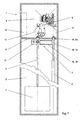
- FIG. 1 shows an elevator installation 1 with a suspension element 2 3 held, and 4 counterweight, in one vertically extending shaft 5, opposite, on and are traversable.
- a shaft ceiling 6 attached drive 7 carries and drives the support means. 2 and the car 3 held by means of the suspension means 2 and Counterweight 4.
- an existing elevator installation 1 provided with engine room 8 with a new drive 7. Of the original needed from the old 9 engine Space is no longer needed for the new drive 7.
- the old prime mover 9 can, as shown in the example, in be left in the assembled state and a later Time to be dismantled, or the room may be for others Tasks are used.
- a controller 10 required for the new drive 7 can, as can be seen in the example, in the former engine room 8, or in the access area of a landing door, or on one another place, preferably in the vicinity of the drive 7, be arranged.
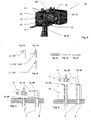
- the new drive 7 is, as in FIGS. 2 and 3 shown, modular design.
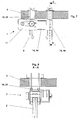
- a drive module 11 is with a traction sheave 12 for the support means 2 of the cabin. 3 and counterweight 4, with one to drive the traction sheave 12 required engine 21 and in the example shown with a 12 required for braking the traction sheave Braking device 14 provided.
- the drive device 13 and the traction sheave 12 are to a drive module 11, such as in Fig. 4 exemplified, assembled.
- the drive module 11 with Provided interfaces 15. These interfaces 15 allow the connection of connecting parts 16.
- This Connecting parts 16 optionally allow attachment the drive module 11 within the shaft fifth For example, to the shaft ceiling 6 as shown in FIGS. 1, 7 and Figure 8 or to the bottom of a conventional one Engine room 8 as shown in Fig. 5 or on the Sockets 17 a previously previously dismantled old Driving machine 9, as shown in Fig. 6.
- the interfaces 15 allow the connection in the other an extension 18, to which a deflection module 19 is connected as shown in Figures 1, 2 and 3.
- the extension 18 together with the drive module 11 and the deflection module 19 allows adjustment of the Tragstoffabstandes according to the requirements of Elevator installation 1.
- the deflection module 19 in turn contains Interfaces 15 which the connection of fasteners as used in the drive module 11 allows.
- the interface 15 of the drive module 11 usn the interface 15 of the deflection module identical executed. This allows for easy installation, as in the Attaching the extension 18 no There is a possibility of confusion.
- extension 18 and the deflection module 19 are such executed that the height of the drive 7 through the Assembly of drive module 11, extension 18 and Deflection module 19 is not changed.
- the interfaces 15 are designed functionally. she allow a modular composition of the drive 7 according to the requirements of the building.
- Another advantage is that the individual Modules and parts transported separately to the installation site can be. As a result, the transport units are small and have a low individual weight. You can for example, with an old, intended for conversion Elevator 9 near the installation site in Buildings are transported.
- this drive 7 to replace existing drives 9 perfectly is suitable by optimizing existing buildings adaptable, i. he can do both within the Shaft 5 as in an existing engine room. 8 to be ordered.
- the support means distance is also easy adjustable. The adjustment of the suspension element spacing does not affect the overall height of the drive 7.
- a guide roller 20th provided, which one, from the support means distance independent, wrapping the traction sheave 12 through the Guaranteed suspension 2.
- the Wrap angle ( ⁇ ) 90 ° to 180 °.
- This wrap can be changed by the arrangement of the guide roller 20 become.
- the drive module 11 can act_direkt, used without the use of the guide roller 20 become. This results depending on the arrangement Wrap angle ( ⁇ ) of 90 ° or 180 °, as in Schematic diagrams Fig. 4a, 4b and 4c shown.
- the drive module 11 is preferably provided with a Monitoring device (not shown) provided, which the correct transmission of power from the Traction sheave 12 to the support means 2 and / or the correct Voltage of the support means 2 monitored.
- a Monitoring device not shown
- the in Fig. 4 illustrated arrangement of the guide roller 20 allows a Control of the transmission of power by, for example the rotational speed of the guide roller 20 with the speed of the Traction sheave 12 is compared. Are the differences? both values noticeable from each other is an incorrect one Transmission of the driving forces.
- the advantage of this design is the fact that the correct transmission of the driving force directly at the drive 7 can be monitored. This will ensure safety and security Availability of the elevator system 1 increases because case-specific the correct measures (maintenance request, Shutdown, etc.) can be initialized quickly.
- the support means 2 has, as in Figs. 4d to 4f illustrated a substantially circular cross-section or it has a substantially flat cross-section on, wherein the transmission of the driving force serving Surface smooth, longitudinally structured, serrated, studded, perforated or of any other structure or, the means of suspension 2 has any cross section.
- the traction sheave is designed such that the transmission of the driving force from the traction sheave on the support means 2 functional is possible.
- the drive 7 is not on a specific support means. 2 limited. He is suitable for a variety of Supporting professional forms. It is advantageous if support means 2 used, which are suitable for small deflection radii suitable. As a result, the drive 7 is particularly small be executed.
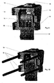
- the motor 21st of the drive module 11 parallel axis to the traction sheave 12th arranged, wherein the motor 21 by a drive belt 23rd is connected to a pulley 22, which is coaxial with Traction sheave 12 is arranged.
- This version is needed little space in the width of the drive 7 and the Transmission of the drive torque is low in vibration.
- the motor 21 is directly coaxial with the traction sheave 12 arranged.
- the advantage of this alternative is to see that the length of the drive 7 is reduced.
- the engine 21 is provided with a Gear connected to the traction sheave shaft 24.
- a Gear connected to the traction sheave shaft 24.
- the brake device is 14 advantageously directly on the traction sheave shaft 24th or the traction sheave 12 acting arranged.
- These Arrangement reduces the risk of brake failure clearly, as the braking force directly into the traction sheave 12 is initiated.
- the advantage of this arrangement is that a safety-compliant braking system for stopping and holding a cabin 3 with intact support means 2 cost can be realized.
- the brake device 14 is directly on the shaft the drive motor 21 arranged acting. This arrangement is inexpensive because a braking device 14 with low Braking torque can be used. This arrangement usually requires more, known in the market, Safety measures to a failure of the connection of Drive motor 21 to catch traction sheave shaft 24.
- the brake device 14 or another Braking device may be arranged on the deflection module 19.
- the traction sheave 12 and / or a Traction shaft 24 and / or the pulley 22nd made in one piece.
- This version allows a Production-optimized and cost-effective execution of the Drive module 11.
- the drive module 11 is provided with interfaces 15, which the cultivation of several connecting parts 16 allows.
- the advantage of this design results from the universal applicability of the drive module 11.
- the Interfaces 15 allow the cultivation of a certain elevator installation 1 required connection parts 16.
- the interfaces 15 are, as in FIGS. 3, 4, 9 and 10 seen, for example, slots or hole arrangements or jaws for receiving connection means.
- the Connecting parts 16 are optional extension 18, Deflection module 19, hanging or support modules 25,26, or there are Tragstoffendeducationen 27 or other tools.
- the Design of the drive module 11 with functional Interfaces 15 allows use of the Drive module 11 for many types of elevators, and this allows a rational and cost-effective production of the product.
- a first advantageous connection part 16 is a Extension 18, which with an end at the Interface 15 of the drive module 11 is arranged, and attached to the other end of a deflection module 19 is.
- the deflection module 19 has identical to the drive module Interface 15 on.
- extension 18 and the Design of the interface 15 to the drive and Deflection module is an adaptation of the drive 7 to the required Tragstoffdistanz allows.
- existing Elevator systems 1 have a certain suspension of the Cab 3 and the counterweight 4 on. From this Auf vonform results in a characterizing distance the suspension element strand, which is usually from the middle the cabin 3, in the vertical projection, to the middle of the counterweight 4 extends.
- the advantage of Extension 18 is that a setting of the Tragstoffabstandes is possible.
- the Deflection module 19 and the drive module 11 have the same Interfaces 15 on. This is particularly advantageous since thereby the design possibilities increase. So can For example, instead of the arrangement, drive module 11 and Deflection module 19, two drive modules 11 are used. This allows the performance of the drive system 7 increase significantly.
- the interface 15 of the drive module 11 and the Deflection module 19 for extension 18 allows a fine adjustability the carrier mean distance. This advantageous Execution allows a setting on the actual existing carrier distance. There is thus no Diagonal pull, causing a wear of the support means. 2 is reduced.
- connection part 16 is a Suspension module 25, which at the interface 15 of Drive module 11 and / or the deflection module 19 is arranged which is the suspension of the drive to a Shaft cover 6 allows, or another connection part 16 is a support module 26, which at the interface 15th the drive module 11 and / or the deflection module 19 is arranged, which is the attachment of the drive 7 in a machine room 8 or on a shaft wall allows.
- the hanging or support modules 25,26 are advantageously with noise or vibration damping materials Mistake.
- the advantage of this embodiment is to be seen in that a building type appropriate attachment can be used.
- the suspension module 25 uses, for example, existing ones Openings in the shaft ceiling 6, or in the bottom of the overhead engine room 8 to the drive 7 to the Canopy 6 to hang, with the machine room in the 8th required counter plates long and narrow are, and between the existing machine sockets 17 are arranged.
- the counter plates can take other forms have, as they are useful for the arrangement result. For example, they can be round if necessary be executed.
- the drive module 11 and / or the deflection module 19 is advantageously with Tragstoffenditatien 27th Mistake.
- the advantage here is that the interfaces reduced to the building, since all the supporting forces Cab 3 and counterweight 4 on the drive unit 7 are guided and about the suspension points of the drive 7 in the building will be initiated.
- the arrangement of the suspensions allows the use a 2: 1 umheksfitten arrangement in elevator systems 1, which hung in the old version directly, or 1: 1 were.
- This arrangement is characterized by a special advantageous design of Tragstoffendriven allows.
- the drive module 11 and / or the deflection module 19 with interface 15 to Attachment of an auxiliary hoist 28 provided.
- the Auxiliary hoist 28 is used for installation-related method of Elevator material and / or installation personnel.
- This supplement allows a particularly efficient sequence of assembly of the drive 7 according to the invention, as in FIG. 13 exemplified.
- the drive 7 according to the invention is using the old elevator system 1 in the vicinity of the Transported installation site and there with the necessary connection parts 16 completed.
- the old Cabin 3 will now be near the topmost stop fixed and secured and become the old carrying organs dismantled.
- the drive according to the invention 7 preferably using the already existing ones Rope penetrations and one in the engine room 8 attached towing device 29, to the shaft ceiling 6 lifted and fixed by means of suspension module 25.
- One Auxiliary hoist 28 is now at, provided on the drive 7, Interface 15 attached.
- any components of the old engine room equipment, like prime mover, control boxes, etc. can help with of the auxiliary hoist 28 are transported. Is the Renewal of the remaining manhole equipment, depending on Reconstruction agreement replaced, the new suspension means 2 retracted, the auxiliary hoist 28 can be removed be and the elevator system 1 is after a short conversion time again available to the customer.
- This described Remodeling process is just one possible example. It shows the advantageous use of the inventive Drive 7 on.
- a supplementary design provides that the attachment Tragstoffendthetic 27 with a monitoring to Determining the suspension medium voltage is provided.
- the elevator associated with the controller 10 and / or Drive control is advantageously in the engine room 8 arranged. Alternatively, it can also be totally or partially in Well 5 or in an easily accessible location, preferably be arranged near the drive.
- remodeling existing elevator systems 1 is often a machine room 8 available.
- the engine room 8 can not usually used elsewhere.
- the electric Connection to the drive 7 is usually easy existing breakthroughs in the shaft ceiling 6 possible. It is particularly advantageous that an existing Engine room 8 is used meaningful. Depending on the existing arrangement or use of the Engine room 8 may be the best arrangement of the controller 10 and / or the drive control can be selected.
Priority Applications (3)
| Application Number | Priority Date | Filing Date | Title |
|---|---|---|---|
| EP05006056.5A EP1553039B1 (fr) | 2004-01-07 | 2004-12-28 | Machinerie pour ascenseur |
| SI200432129T SI1553039T1 (sl) | 2004-01-07 | 2004-12-28 | Pogon za dvigalo |
| PL05006056T PL1553039T3 (pl) | 2004-01-07 | 2004-12-28 | Napęd instalacji dźwigowej |
Applications Claiming Priority (4)
| Application Number | Priority Date | Filing Date | Title |
|---|---|---|---|
| EP04405010 | 2004-01-07 | ||
| EP04405010 | 2004-01-07 | ||
| EP04030856.1A EP1555236B1 (fr) | 2004-01-07 | 2004-12-28 | Entraînement d'ascenseur et procédés de conversion et d'installation d'un ;entraînement d'ascenseur |
| EP05006056.5A EP1553039B1 (fr) | 2004-01-07 | 2004-12-28 | Machinerie pour ascenseur |
Related Parent Applications (3)
| Application Number | Title | Priority Date | Filing Date |
|---|---|---|---|
| EP04030856.1 Division | 2004-12-28 | ||
| EP04030856.1A Division EP1555236B1 (fr) | 2004-01-07 | 2004-12-28 | Entraînement d'ascenseur et procédés de conversion et d'installation d'un ;entraînement d'ascenseur |
| EP04030856.1A Division-Into EP1555236B1 (fr) | 2004-01-07 | 2004-12-28 | Entraînement d'ascenseur et procédés de conversion et d'installation d'un ;entraînement d'ascenseur |
Publications (3)
| Publication Number | Publication Date |
|---|---|
| EP1553039A2 true EP1553039A2 (fr) | 2005-07-13 |
| EP1553039A3 EP1553039A3 (fr) | 2007-03-07 |
| EP1553039B1 EP1553039B1 (fr) | 2013-12-25 |
Family
ID=34593654
Family Applications (4)
| Application Number | Title | Priority Date | Filing Date |
|---|---|---|---|
| EP04030856.1A Active EP1555236B1 (fr) | 2004-01-07 | 2004-12-28 | Entraînement d'ascenseur et procédés de conversion et d'installation d'un ;entraînement d'ascenseur |
| EP05006056.5A Revoked EP1553039B1 (fr) | 2004-01-07 | 2004-12-28 | Machinerie pour ascenseur |
| EP05104962A Active EP1588978B1 (fr) | 2004-01-07 | 2004-12-28 | Entraînement d'ascenseur |
| EP14195765.4A Active EP2860144B1 (fr) | 2004-01-07 | 2004-12-28 | Entraînement pour un ascenseur |
Family Applications Before (1)
| Application Number | Title | Priority Date | Filing Date |
|---|---|---|---|
| EP04030856.1A Active EP1555236B1 (fr) | 2004-01-07 | 2004-12-28 | Entraînement d'ascenseur et procédés de conversion et d'installation d'un ;entraînement d'ascenseur |
Family Applications After (2)
| Application Number | Title | Priority Date | Filing Date |
|---|---|---|---|
| EP05104962A Active EP1588978B1 (fr) | 2004-01-07 | 2004-12-28 | Entraînement d'ascenseur |
| EP14195765.4A Active EP2860144B1 (fr) | 2004-01-07 | 2004-12-28 | Entraînement pour un ascenseur |
Country Status (2)
| Country | Link |
|---|---|
| EP (4) | EP1555236B1 (fr) |
| PL (2) | PL1555236T3 (fr) |
Families Citing this family (2)
| Publication number | Priority date | Publication date | Assignee | Title |
|---|---|---|---|---|
| EP1886957A1 (fr) | 2006-08-11 | 2008-02-13 | Inventio Ag | Courroie d'élévateur pour un élévateur et procédé de fabrication d'une telle courroie d'élévateur |
| DE202008001786U1 (de) | 2007-03-12 | 2008-12-24 | Inventio Ag | Aufzugsanlage, Tragmittel für eine Aufzugsanlage und Vorrichtung zur Herstellung eines Tragmittels |
Citations (5)
| Publication number | Priority date | Publication date | Assignee | Title |
|---|---|---|---|---|
| JPH09151059A (ja) * | 1995-12-01 | 1997-06-10 | Hitachi Ltd | エレベータ装置 |
| WO2002000541A1 (fr) * | 2000-06-21 | 2002-01-03 | Otis Elevator Company | Terminaison pivotante pour cable d'ascenseur |
| WO2002026611A1 (fr) * | 2000-09-27 | 2002-04-04 | Inventio Ag | Ascenseur comprenant une unite d'entrainement montee dans une partie laterale superieure de la cage d'ascenseur |
| WO2003043927A2 (fr) * | 2001-11-23 | 2003-05-30 | Inventio Ag | Ascenseur comprenant un moyen de transmission de type courroie, notamment une courroie dentee, en tant que moyen de support ou moyen d'entrainement |
| EP1333000A1 (fr) * | 2002-02-05 | 2003-08-06 | Monitor S.p.A. | Ascenseur à poulie de traction sans salle de machines |
Family Cites Families (9)
| Publication number | Priority date | Publication date | Assignee | Title |
|---|---|---|---|---|
| FI84050C (fi) * | 1988-04-18 | 1991-10-10 | Kone Oy | Foerfarande foer kontroll av friktionen mellan drivskiva och baerlinor till en hiss. |
| JPH0761744A (ja) * | 1993-08-18 | 1995-03-07 | Otis Elevator Co | 巻き上げ式エレベーター |
| EP0763495A1 (fr) | 1995-09-15 | 1997-03-19 | Inventio Ag | Chassis de machine |
| DE59711862D1 (de) * | 1996-11-11 | 2004-09-23 | Inventio Ag | Aufzugsanlage mit im Aufzugsschacht angeordneter Antriebseinheit |
| DE29924761U1 (de) * | 1998-02-26 | 2005-06-23 | Otis Elevator Co., Farmington | Zugelement für einen Aufzug |
| JP4391649B2 (ja) * | 1999-12-20 | 2009-12-24 | 三菱電機株式会社 | エレベータの巻上機支持装置 |
| US6619433B1 (en) * | 2000-07-24 | 2003-09-16 | Otis Elevator Company | Elevator system using minimal building space |
| JP4828084B2 (ja) * | 2001-03-29 | 2011-11-30 | 三菱電機株式会社 | 巻上機の据付方法 |
| SG110016A1 (en) * | 2002-02-18 | 2005-04-28 | Inventio Ag | Engine frame with counter-roller support for an elevator drive |
-
2004
- 2004-12-28 EP EP04030856.1A patent/EP1555236B1/fr active Active
- 2004-12-28 PL PL04030856T patent/PL1555236T3/pl unknown
- 2004-12-28 EP EP05006056.5A patent/EP1553039B1/fr not_active Revoked
- 2004-12-28 EP EP05104962A patent/EP1588978B1/fr active Active
- 2004-12-28 EP EP14195765.4A patent/EP2860144B1/fr active Active
- 2004-12-28 PL PL05006056T patent/PL1553039T3/pl unknown
Patent Citations (5)
| Publication number | Priority date | Publication date | Assignee | Title |
|---|---|---|---|---|
| JPH09151059A (ja) * | 1995-12-01 | 1997-06-10 | Hitachi Ltd | エレベータ装置 |
| WO2002000541A1 (fr) * | 2000-06-21 | 2002-01-03 | Otis Elevator Company | Terminaison pivotante pour cable d'ascenseur |
| WO2002026611A1 (fr) * | 2000-09-27 | 2002-04-04 | Inventio Ag | Ascenseur comprenant une unite d'entrainement montee dans une partie laterale superieure de la cage d'ascenseur |
| WO2003043927A2 (fr) * | 2001-11-23 | 2003-05-30 | Inventio Ag | Ascenseur comprenant un moyen de transmission de type courroie, notamment une courroie dentee, en tant que moyen de support ou moyen d'entrainement |
| EP1333000A1 (fr) * | 2002-02-05 | 2003-08-06 | Monitor S.p.A. | Ascenseur à poulie de traction sans salle de machines |
Also Published As
| Publication number | Publication date |
|---|---|
| EP2860144A1 (fr) | 2015-04-15 |
| EP1588978B1 (fr) | 2007-07-18 |
| EP2860144B1 (fr) | 2016-09-28 |
| EP1553039B1 (fr) | 2013-12-25 |
| PL1555236T3 (pl) | 2019-03-29 |
| EP1555236B1 (fr) | 2018-09-26 |
| EP1553039A3 (fr) | 2007-03-07 |
| EP1555236A1 (fr) | 2005-07-20 |
| EP1588978A2 (fr) | 2005-10-26 |
| EP1588978A3 (fr) | 2006-05-17 |
| PL1553039T3 (pl) | 2014-05-30 |
Similar Documents
| Publication | Publication Date | Title |
|---|---|---|
| EP0917518B1 (fr) | Ascenseur a poulies motrices | |
| DE60007512T2 (de) | Treibscheibenaufzug | |
| EP1621509B1 (fr) | Positionnement de machine d'entraînement d'ascenseur | |
| EP1700809B1 (fr) | Système d'ascenseur | |
| EP2082983B1 (fr) | Installation d'ascenseur | |
| EP1772411A1 (fr) | Méthode pour installer un moyen de support d'une cabine d'ascenseur sur une cabine d'ascenseur et dans une gaine d'ascenseur | |
| DE29924747U1 (de) | Aufzugsystem mit Antriebsmotor zwischen Aufzugfahrkorb und Aufzugschacht-Seitenwand | |
| EP2346771B1 (fr) | Procédé de modernisation destiné à des installations d'ascenseur | |
| WO2019034381A1 (fr) | Système d'ascenseur | |
| WO2002068307A1 (fr) | Agencement d'elements d'equilibrage de poids | |
| DE3523187A1 (de) | Gebaeudeaufzug | |
| DE102006037253A1 (de) | Aufzugsanlage | |
| EP1555236B1 (fr) | Entraînement d'ascenseur et procédés de conversion et d'installation d'un ;entraînement d'ascenseur | |
| EP3931141B1 (fr) | Système d'ascenseur | |
| EP1555232B1 (fr) | Procédé de conversion et de installation d'un entraînement d'asceneur | |
| DE10319731B4 (de) | Aufzug | |
| EP1669315A1 (fr) | Méthode et dispositif d'entraînement de secours pour entraîner une cabine d'ascenseur | |
| EP1785386A1 (fr) | Méthode d'installation d'un ascenseur et ascenseur pour cette méthode | |
| DE10154171A1 (de) | Modernisierung von Hydraulikaufzügen | |
| DE10300992A1 (de) | Aufzug mit getrennter Fahrkorbaufhängung | |
| EP1673301B1 (fr) | Systeme d'entrainement concu pour des salles de machinerie etroites | |
| EP3235770B1 (fr) | Procede de reequipement d'un ascenseur et ascenseur correspondant | |
| EP1045811B1 (fr) | Ascenseur a cables avec poulie motrice | |
| DE20320076U1 (de) | Antriebssystem für enge Triebwerksräume | |
| DE19839864A1 (de) | Vorrichtung zur Vertikalverlagerung von Lastaufnahmemitteln für Güter und/oder Personen |
Legal Events
| Date | Code | Title | Description |
|---|---|---|---|
| PUAI | Public reference made under article 153(3) epc to a published international application that has entered the european phase |
Free format text: ORIGINAL CODE: 0009012 |
|
| AK | Designated contracting states |
Kind code of ref document: A2 Designated state(s): AT BE BG CH CY CZ DE DK EE ES FI FR GB GR HU IE IS IT LI LT LU MC NL PL PT RO SE SI SK TR |
|
| AX | Request for extension of the european patent |
Extension state: AL BA HR LV MK YU |
|
| PUAL | Search report despatched |
Free format text: ORIGINAL CODE: 0009013 |
|
| AK | Designated contracting states |
Kind code of ref document: A3 Designated state(s): AT BE BG CH CY CZ DE DK EE ES FI FR GB GR HU IE IS IT LI LT LU MC NL PL PT RO SE SI SK TR |
|
| AX | Request for extension of the european patent |
Extension state: AL BA HR LV MK YU |
|
| RIC1 | Information provided on ipc code assigned before grant |
Ipc: B66B 7/08 20060101ALI20070131BHEP Ipc: B66B 11/00 20060101AFI20050429BHEP |
|
| 17P | Request for examination filed |
Effective date: 20070904 |
|
| AKX | Designation fees paid |
Designated state(s): AT BE BG CH CY CZ DE DK EE ES FI FR GB GR HU IE IS IT LI LT LU MC NL PL PT RO SE SI SK TR |
|
| GRAP | Despatch of communication of intention to grant a patent |
Free format text: ORIGINAL CODE: EPIDOSNIGR1 |
|
| INTG | Intention to grant announced |
Effective date: 20130809 |
|
| RIN1 | Information on inventor provided before grant (corrected) |
Inventor name: STOCKER, RUEDI Inventor name: LIEBETRAU, CHRISTOPH |
|
| GRAS | Grant fee paid |
Free format text: ORIGINAL CODE: EPIDOSNIGR3 |
|
| GRAA | (expected) grant |
Free format text: ORIGINAL CODE: 0009210 |
|
| AC | Divisional application: reference to earlier application |
Ref document number: 1555236 Country of ref document: EP Kind code of ref document: P |
|
| AK | Designated contracting states |
Kind code of ref document: B1 Designated state(s): AT BE BG CH CY CZ DE DK EE ES FI FR GB GR HU IE IS IT LI LT LU MC NL PL PT RO SE SI SK TR |
|
| REG | Reference to a national code |
Ref country code: GB Ref legal event code: FG4D Free format text: NOT ENGLISH |
|
| REG | Reference to a national code |
Ref country code: CH Ref legal event code: EP |
|
| REG | Reference to a national code |
Ref country code: AT Ref legal event code: REF Ref document number: 646512 Country of ref document: AT Kind code of ref document: T Effective date: 20140115 |
|
| REG | Reference to a national code |
Ref country code: IE Ref legal event code: FG4D Free format text: LANGUAGE OF EP DOCUMENT: GERMAN |
|
| REG | Reference to a national code |
Ref country code: DE Ref legal event code: R096 Ref document number: 502004014479 Country of ref document: DE Effective date: 20140213 |
|
| REG | Reference to a national code |
Ref country code: NL Ref legal event code: T3 |
|
| REG | Reference to a national code |
Ref country code: PT Ref legal event code: SC4A Free format text: AVAILABILITY OF NATIONAL TRANSLATION Effective date: 20140304 |
|
| REG | Reference to a national code |
Ref country code: SE Ref legal event code: TRGR Ref country code: RO Ref legal event code: EPE |
|
| REG | Reference to a national code |
Ref country code: ES Ref legal event code: FG2A Ref document number: 2450167 Country of ref document: ES Kind code of ref document: T3 Effective date: 20140324 |
|
| PG25 | Lapsed in a contracting state [announced via postgrant information from national office to epo] |
Ref country code: LT Free format text: LAPSE BECAUSE OF FAILURE TO SUBMIT A TRANSLATION OF THE DESCRIPTION OR TO PAY THE FEE WITHIN THE PRESCRIBED TIME-LIMIT Effective date: 20131225 |
|
| REG | Reference to a national code |
Ref country code: GR Ref legal event code: EP Ref document number: 20140400562 Country of ref document: GR Effective date: 20140416 |
|
| REG | Reference to a national code |
Ref country code: LT Ref legal event code: MG4D Effective date: 20131022 |
|
| REG | Reference to a national code |
Ref country code: PL Ref legal event code: T3 |
|
| REG | Reference to a national code |
Ref country code: SK Ref legal event code: T3 Ref document number: E 15881 Country of ref document: SK |
|
| PG25 | Lapsed in a contracting state [announced via postgrant information from national office to epo] |
Ref country code: EE Free format text: LAPSE BECAUSE OF FAILURE TO SUBMIT A TRANSLATION OF THE DESCRIPTION OR TO PAY THE FEE WITHIN THE PRESCRIBED TIME-LIMIT Effective date: 20131225 Ref country code: IS Free format text: LAPSE BECAUSE OF FAILURE TO SUBMIT A TRANSLATION OF THE DESCRIPTION OR TO PAY THE FEE WITHIN THE PRESCRIBED TIME-LIMIT Effective date: 20140425 |
|
| PG25 | Lapsed in a contracting state [announced via postgrant information from national office to epo] |
Ref country code: CY Free format text: LAPSE BECAUSE OF FAILURE TO SUBMIT A TRANSLATION OF THE DESCRIPTION OR TO PAY THE FEE WITHIN THE PRESCRIBED TIME-LIMIT Effective date: 20131225 Ref country code: CZ Free format text: LAPSE BECAUSE OF FAILURE TO SUBMIT A TRANSLATION OF THE DESCRIPTION OR TO PAY THE FEE WITHIN THE PRESCRIBED TIME-LIMIT Effective date: 20131225 |
|
| REG | Reference to a national code |
Ref country code: DE Ref legal event code: R026 Ref document number: 502004014479 Country of ref document: DE |
|
| PLBI | Opposition filed |
Free format text: ORIGINAL CODE: 0009260 |
|
| REG | Reference to a national code |
Ref country code: HU Ref legal event code: AG4A Ref document number: E020056 Country of ref document: HU |
|
| PG25 | Lapsed in a contracting state [announced via postgrant information from national office to epo] |
Ref country code: MC Free format text: LAPSE BECAUSE OF FAILURE TO SUBMIT A TRANSLATION OF THE DESCRIPTION OR TO PAY THE FEE WITHIN THE PRESCRIBED TIME-LIMIT Effective date: 20131225 |
|
| PLAB | Opposition data, opponent's data or that of the opponent's representative modified |
Free format text: ORIGINAL CODE: 0009299OPPO |
|
| 26 | Opposition filed |
Opponent name: OTIS ELEVATOR COMPANY Effective date: 20140922 Opponent name: THYSSENKRUPP ELEVATOR AG Effective date: 20140924 |
|
| PLAX | Notice of opposition and request to file observation + time limit sent |
Free format text: ORIGINAL CODE: EPIDOSNOBS2 |
|
| PG25 | Lapsed in a contracting state [announced via postgrant information from national office to epo] |
Ref country code: DK Free format text: LAPSE BECAUSE OF FAILURE TO SUBMIT A TRANSLATION OF THE DESCRIPTION OR TO PAY THE FEE WITHIN THE PRESCRIBED TIME-LIMIT Effective date: 20131225 |
|
| R26 | Opposition filed (corrected) |
Opponent name: THYSSENKRUPP ELEVATOR AG Effective date: 20140924 |
|
| REG | Reference to a national code |
Ref country code: DE Ref legal event code: R026 Ref document number: 502004014479 Country of ref document: DE Effective date: 20140922 |
|
| PLBB | Reply of patent proprietor to notice(s) of opposition received |
Free format text: ORIGINAL CODE: EPIDOSNOBS3 |
|
| PG25 | Lapsed in a contracting state [announced via postgrant information from national office to epo] |
Ref country code: TR Free format text: LAPSE BECAUSE OF FAILURE TO SUBMIT A TRANSLATION OF THE DESCRIPTION OR TO PAY THE FEE WITHIN THE PRESCRIBED TIME-LIMIT Effective date: 20131225 |
|
| PG25 | Lapsed in a contracting state [announced via postgrant information from national office to epo] |
Ref country code: BG Free format text: LAPSE BECAUSE OF FAILURE TO SUBMIT A TRANSLATION OF THE DESCRIPTION OR TO PAY THE FEE WITHIN THE PRESCRIBED TIME-LIMIT Effective date: 20131225 Ref country code: LU Free format text: LAPSE BECAUSE OF NON-PAYMENT OF DUE FEES Effective date: 20131228 |
|
| REG | Reference to a national code |
Ref country code: FR Ref legal event code: PLFP Year of fee payment: 12 |
|
| PGFP | Annual fee paid to national office [announced via postgrant information from national office to epo] |
Ref country code: CH Payment date: 20151223 Year of fee payment: 12 Ref country code: FI Payment date: 20151211 Year of fee payment: 12 Ref country code: IE Payment date: 20151223 Year of fee payment: 12 Ref country code: GR Payment date: 20151217 Year of fee payment: 12 Ref country code: GB Payment date: 20151221 Year of fee payment: 12 Ref country code: DE Payment date: 20151211 Year of fee payment: 12 |
|
| PGFP | Annual fee paid to national office [announced via postgrant information from national office to epo] |
Ref country code: ES Payment date: 20151214 Year of fee payment: 12 Ref country code: FR Payment date: 20151221 Year of fee payment: 12 Ref country code: PL Payment date: 20151123 Year of fee payment: 12 Ref country code: SE Payment date: 20151221 Year of fee payment: 12 Ref country code: AT Payment date: 20151222 Year of fee payment: 12 Ref country code: BE Payment date: 20151221 Year of fee payment: 12 Ref country code: SI Payment date: 20151123 Year of fee payment: 12 Ref country code: HU Payment date: 20151221 Year of fee payment: 12 Ref country code: RO Payment date: 20151123 Year of fee payment: 12 Ref country code: SK Payment date: 20151223 Year of fee payment: 12 Ref country code: PT Payment date: 20151223 Year of fee payment: 12 Ref country code: NL Payment date: 20151221 Year of fee payment: 12 |
|
| PGFP | Annual fee paid to national office [announced via postgrant information from national office to epo] |
Ref country code: IT Payment date: 20151228 Year of fee payment: 12 |
|
| RDAF | Communication despatched that patent is revoked |
Free format text: ORIGINAL CODE: EPIDOSNREV1 |
|
| STAA | Information on the status of an ep patent application or granted ep patent |
Free format text: STATUS: THE PATENT HAS BEEN GRANTED |
|
| REG | Reference to a national code |
Ref country code: DE Ref legal event code: R064 Ref document number: 502004014479 Country of ref document: DE Ref country code: DE Ref legal event code: R103 Ref document number: 502004014479 Country of ref document: DE |
|
| RDAG | Patent revoked |
Free format text: ORIGINAL CODE: 0009271 |
|
| STAA | Information on the status of an ep patent application or granted ep patent |
Free format text: STATUS: PATENT REVOKED |
|
| REG | Reference to a national code |
Ref country code: CH Ref legal event code: PLX |
|
| 27W | Patent revoked |
Effective date: 20170102 |
|
| GBPR | Gb: patent revoked under art. 102 of the ep convention designating the uk as contracting state |
Effective date: 20170102 |
|
| PG25 | Lapsed in a contracting state [announced via postgrant information from national office to epo] |
Ref country code: BE Free format text: LAPSE BECAUSE OF NON-PAYMENT OF DUE FEES Effective date: 20161231 |
|
| PG25 | Lapsed in a contracting state [announced via postgrant information from national office to epo] |
Ref country code: CH Free format text: LAPSE BECAUSE OF THE APPLICANT RENOUNCES Effective date: 20131225 Ref country code: LI Free format text: LAPSE BECAUSE OF THE APPLICANT RENOUNCES Effective date: 20131225 |
|
| REG | Reference to a national code |
Ref country code: AT Ref legal event code: MA03 Ref document number: 646512 Country of ref document: AT Kind code of ref document: T Effective date: 20170102 |
|
| REG | Reference to a national code |
Ref country code: SI Ref legal event code: KO00 Effective date: 20170818 |
|
| REG | Reference to a national code |
Ref country code: SE Ref legal event code: ECNC |
|
| PG25 | Lapsed in a contracting state [announced via postgrant information from national office to epo] |
Ref country code: HU Free format text: LAPSE BECAUSE OF NON-PAYMENT OF DUE FEES Effective date: 20161229 Ref country code: SI Free format text: LAPSE BECAUSE OF NON-PAYMENT OF DUE FEES Effective date: 20161229 |
|
| STAA | Information on the status of an ep patent application or granted ep patent |
Free format text: STATUS: PATENT REVOKED |
|
| PG25 | Lapsed in a contracting state [announced via postgrant information from national office to epo] |
Ref country code: ES Free format text: LAPSE BECAUSE OF NON-PAYMENT OF DUE FEES Effective date: 20161229 |