EP1553039A2 - Drive for an elevator - Google Patents
Drive for an elevator Download PDFInfo
- Publication number
- EP1553039A2 EP1553039A2 EP05006056A EP05006056A EP1553039A2 EP 1553039 A2 EP1553039 A2 EP 1553039A2 EP 05006056 A EP05006056 A EP 05006056A EP 05006056 A EP05006056 A EP 05006056A EP 1553039 A2 EP1553039 A2 EP 1553039A2
- Authority
- EP
- European Patent Office
- Prior art keywords
- drive
- module
- deflection
- traction sheave
- drive module
- Prior art date
- Legal status (The legal status is an assumption and is not a legal conclusion. Google has not performed a legal analysis and makes no representation as to the accuracy of the status listed.)
- Granted
Links
Images


Classifications
-
- B—PERFORMING OPERATIONS; TRANSPORTING
- B66—HOISTING; LIFTING; HAULING
- B66B—ELEVATORS; ESCALATORS OR MOVING WALKWAYS
- B66B11/00—Main component parts of lifts in, or associated with, buildings or other structures
-
- B—PERFORMING OPERATIONS; TRANSPORTING
- B66—HOISTING; LIFTING; HAULING
- B66B—ELEVATORS; ESCALATORS OR MOVING WALKWAYS
- B66B7/00—Other common features of elevators
- B66B7/06—Arrangements of ropes or cables
- B66B7/08—Arrangements of ropes or cables for connection to the cars or cages, e.g. couplings
Definitions
- the invention relates to an elevator system with a Drive, with a cabin and a counterweight, which Drive with at least one traction sheave and with at least one to drive the traction sheave required motor and with a deflection module with Deflection pulley is provided, the engine and the Traction sheave are assembled to a drive module and Suspension means over the traction sheave and the pulley are guided.
- a lift facility aims to transport people and Goods within a building between floors.
- a Cabin serves to accommodate the persons and goods.
- One Drive drives by means of suspension means the car, which thereby in a vertically extending shaft up and down is moved.
- the suspension element connects the cabin with a counterweight. It is about a traction sheave guided.
- the traction sheave transfers to the process or to hold required force on the support means.
- the Traction sheave is from a drive device and / or driven by a braking device or held.
- Another type of drive drives the cabin by means of hydraulic lifting devices.
- the driving and holding force is doing so from a pump unit directly via a piston acting, or indirectly by means of a rope or chain hoist acting, transferred to the cabin.
- Both drive types have specific Use properties on, they are also wear subjected.
- the usage properties are for example the driving speed or the load capacity for the Lift system is designed. Wear occurs for example, by prolonged use of the Elevator system, which leads to signs of wear Parts of the elevator system leads. Change the Usage requirements or wear is too big must be the drive or at most the entire elevator system be replaced or renewed.
- document EP 0 763 495 shows a drive machine, which by changing the installation slope a change causes the support means distance (a).
- support means distance is the distance between the on the prime mover accumulating suspension element strand and the expiring Designated suspension element strand.
- the shown drive machine has the disadvantage of being on a machine room with specially prepared Auflägesockeln is dependent and therefore not for installation in an existing Engine room or in a shaft is suitable, a Change in the suspension element spacing (a) a change the wrap angle ( ⁇ ) causes and the unit large is what happens when inserting into an existing building adversely affects.
- the wrap angle ( ⁇ ) denotes the angle over which the suspension means the traction sheave entwine. The from the traction sheave on the suspension means transferable force is usually dependent on Wrap angle ( ⁇ ).
- the object of the invention is now a drive for a To provide elevator installation, which is for replacement existing drives is the best on existing building is adaptable, i. that he should be without further structural measures in an existing Engine room or arranged inside the shaft space can be.
- the support means distance should be easy be adjustable and the drive should be small in size exhibit.
- the elevator system includes a drive, an on Carrying means held cabin and a counterweight.
- the Cabin and the counterweight are in a vertical extending shaft oppositely up and down movably arranged.
- the suspension element connects the cabin to the counterweight and the support means is from the drive by means of at least worn and driven by a traction sheave.
- the drive is with the traction sheave, with at least one to drive the Traction sheave required engine and with a deflection module Mistake.
- the engine and the traction sheave are to one Drive module assembled.
- the core function that Drive is perceived by this drive module.
- the drive module also contains one Braking device.
- the drive module and the Deflection module by means of an extension with each other connected, wherein the drive module and the deflection module with Interfaces are provided which together with the Extension an adaptation of the drive to a allow required Tragstoffdistanz.
- the drive module and / or the deflection module with Provided connecting parts, which for fastening the Drive inside the shaft or in the engine room are used.
- the drive is optimal adaptable for existing buildings and he can - under Use of the connection parts - without further construction Measures in an existing engine room or be arranged within a shaft.
- Carrier spacing may be using extension and the interfaces to drive and deflection module easy be adapted to predetermined Tragseildistanzen.
- the modular design of drive module and deflection module as well their possibility of attachment by means of their own Connecting parts allows small dimensions, since Load-bearing forces can be initiated directly into the building.
- the Connecting parts are according to the building requirements designed.
- the drive module and the deflection module have the corresponding interfaces. The parts become thereby can be produced efficiently and in large quantities. This gives economically optimal manufacturing conditions.
- the division into modules and parts makes the drive easy transportable, he can, for example, within a existing building, with an existing elevator system be transported to the vicinity of the installation site. He is thus excellent for the conversion of elevator systems in suitable for existing buildings.
- Another advantage is that the installation height of the drive, regardless of the support means distance, not is changed, and thus no dependence of the height space requirement consists of the support means distance.
- the drive module provided with a guide roller.
- the leadership is in Drive module placed so that they, regardless of the Tragstoffdistanz, a firmly defined wrap the traction sheave allows. This eliminates costly Plant-related evidence of sufficient propulsion, since for the proof calculation few firmly defined Wrap angle can be considered.
- the Drive module can be particularly economical getting produced.
- the drive module and / or the deflection module is a Fastening integrated for attachment of suspension element ends.
- This attachment is at suspended elevator systems used advantageously. All relevant support points of the drive are thus placed in the drive itself. By the load bearing points specified by the drive will cover the entire Suspension force of the elevator system added.
- the Drive machine is thus excellent for the application suitable in existing buildings since the initiation of the Forces in the building is reduced to a few places.
- the drive module is advantageously a Monitoring device arranged, which the correct Transmission of the driving forces monitored on the propellants.
- An insufficient transfer of the driving forces will For example, determined by the speed of the Guide roller compared with the speed of the traction sheave becomes.
- predefined ones Security measures initiated. This will be the Safety and availability of the elevator system increased since case-specific the right measures (Maintenance request, shutdown, etc.) initialized can be.
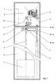
- FIG. 1 shows an elevator installation 1 with a suspension element 2 3 held, and 4 counterweight, in one vertically extending shaft 5, opposite, on and are traversable.
- a shaft ceiling 6 attached drive 7 carries and drives the support means. 2 and the car 3 held by means of the suspension means 2 and Counterweight 4.
- an existing elevator installation 1 provided with engine room 8 with a new drive 7. Of the original needed from the old 9 engine Space is no longer needed for the new drive 7.
- the old prime mover 9 can, as shown in the example, in be left in the assembled state and a later Time to be dismantled, or the room may be for others Tasks are used.
- a controller 10 required for the new drive 7 can, as can be seen in the example, in the former engine room 8, or in the access area of a landing door, or on one another place, preferably in the vicinity of the drive 7, be arranged.
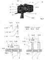
- the new drive 7 is, as in FIGS. 2 and 3 shown, modular design.
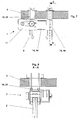
- a drive module 11 is with a traction sheave 12 for the support means 2 of the cabin. 3 and counterweight 4, with one to drive the traction sheave 12 required engine 21 and in the example shown with a 12 required for braking the traction sheave Braking device 14 provided.
- the drive device 13 and the traction sheave 12 are to a drive module 11, such as in Fig. 4 exemplified, assembled.
- the drive module 11 with Provided interfaces 15. These interfaces 15 allow the connection of connecting parts 16.
- This Connecting parts 16 optionally allow attachment the drive module 11 within the shaft fifth For example, to the shaft ceiling 6 as shown in FIGS. 1, 7 and Figure 8 or to the bottom of a conventional one Engine room 8 as shown in Fig. 5 or on the Sockets 17 a previously previously dismantled old Driving machine 9, as shown in Fig. 6.
- the interfaces 15 allow the connection in the other an extension 18, to which a deflection module 19 is connected as shown in Figures 1, 2 and 3.
- the extension 18 together with the drive module 11 and the deflection module 19 allows adjustment of the Tragstoffabstandes according to the requirements of Elevator installation 1.
- the deflection module 19 in turn contains Interfaces 15 which the connection of fasteners as used in the drive module 11 allows.
- the interface 15 of the drive module 11 usn the interface 15 of the deflection module identical executed. This allows for easy installation, as in the Attaching the extension 18 no There is a possibility of confusion.
- extension 18 and the deflection module 19 are such executed that the height of the drive 7 through the Assembly of drive module 11, extension 18 and Deflection module 19 is not changed.
- the interfaces 15 are designed functionally. she allow a modular composition of the drive 7 according to the requirements of the building.
- Another advantage is that the individual Modules and parts transported separately to the installation site can be. As a result, the transport units are small and have a low individual weight. You can for example, with an old, intended for conversion Elevator 9 near the installation site in Buildings are transported.
- this drive 7 to replace existing drives 9 perfectly is suitable by optimizing existing buildings adaptable, i. he can do both within the Shaft 5 as in an existing engine room. 8 to be ordered.
- the support means distance is also easy adjustable. The adjustment of the suspension element spacing does not affect the overall height of the drive 7.
- a guide roller 20th provided, which one, from the support means distance independent, wrapping the traction sheave 12 through the Guaranteed suspension 2.
- the Wrap angle ( ⁇ ) 90 ° to 180 °.
- This wrap can be changed by the arrangement of the guide roller 20 become.
- the drive module 11 can act_direkt, used without the use of the guide roller 20 become. This results depending on the arrangement Wrap angle ( ⁇ ) of 90 ° or 180 °, as in Schematic diagrams Fig. 4a, 4b and 4c shown.
- the drive module 11 is preferably provided with a Monitoring device (not shown) provided, which the correct transmission of power from the Traction sheave 12 to the support means 2 and / or the correct Voltage of the support means 2 monitored.
- a Monitoring device not shown
- the in Fig. 4 illustrated arrangement of the guide roller 20 allows a Control of the transmission of power by, for example the rotational speed of the guide roller 20 with the speed of the Traction sheave 12 is compared. Are the differences? both values noticeable from each other is an incorrect one Transmission of the driving forces.
- the advantage of this design is the fact that the correct transmission of the driving force directly at the drive 7 can be monitored. This will ensure safety and security Availability of the elevator system 1 increases because case-specific the correct measures (maintenance request, Shutdown, etc.) can be initialized quickly.
- the support means 2 has, as in Figs. 4d to 4f illustrated a substantially circular cross-section or it has a substantially flat cross-section on, wherein the transmission of the driving force serving Surface smooth, longitudinally structured, serrated, studded, perforated or of any other structure or, the means of suspension 2 has any cross section.
- the traction sheave is designed such that the transmission of the driving force from the traction sheave on the support means 2 functional is possible.
- the drive 7 is not on a specific support means. 2 limited. He is suitable for a variety of Supporting professional forms. It is advantageous if support means 2 used, which are suitable for small deflection radii suitable. As a result, the drive 7 is particularly small be executed.
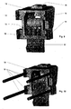
- the motor 21st of the drive module 11 parallel axis to the traction sheave 12th arranged, wherein the motor 21 by a drive belt 23rd is connected to a pulley 22, which is coaxial with Traction sheave 12 is arranged.
- This version is needed little space in the width of the drive 7 and the Transmission of the drive torque is low in vibration.
- the motor 21 is directly coaxial with the traction sheave 12 arranged.
- the advantage of this alternative is to see that the length of the drive 7 is reduced.
- the engine 21 is provided with a Gear connected to the traction sheave shaft 24.
- a Gear connected to the traction sheave shaft 24.
- the brake device is 14 advantageously directly on the traction sheave shaft 24th or the traction sheave 12 acting arranged.
- These Arrangement reduces the risk of brake failure clearly, as the braking force directly into the traction sheave 12 is initiated.
- the advantage of this arrangement is that a safety-compliant braking system for stopping and holding a cabin 3 with intact support means 2 cost can be realized.
- the brake device 14 is directly on the shaft the drive motor 21 arranged acting. This arrangement is inexpensive because a braking device 14 with low Braking torque can be used. This arrangement usually requires more, known in the market, Safety measures to a failure of the connection of Drive motor 21 to catch traction sheave shaft 24.
- the brake device 14 or another Braking device may be arranged on the deflection module 19.
- the traction sheave 12 and / or a Traction shaft 24 and / or the pulley 22nd made in one piece.
- This version allows a Production-optimized and cost-effective execution of the Drive module 11.
- the drive module 11 is provided with interfaces 15, which the cultivation of several connecting parts 16 allows.
- the advantage of this design results from the universal applicability of the drive module 11.
- the Interfaces 15 allow the cultivation of a certain elevator installation 1 required connection parts 16.
- the interfaces 15 are, as in FIGS. 3, 4, 9 and 10 seen, for example, slots or hole arrangements or jaws for receiving connection means.
- the Connecting parts 16 are optional extension 18, Deflection module 19, hanging or support modules 25,26, or there are Tragstoffendeducationen 27 or other tools.
- the Design of the drive module 11 with functional Interfaces 15 allows use of the Drive module 11 for many types of elevators, and this allows a rational and cost-effective production of the product.
- a first advantageous connection part 16 is a Extension 18, which with an end at the Interface 15 of the drive module 11 is arranged, and attached to the other end of a deflection module 19 is.
- the deflection module 19 has identical to the drive module Interface 15 on.
- extension 18 and the Design of the interface 15 to the drive and Deflection module is an adaptation of the drive 7 to the required Tragstoffdistanz allows.
- existing Elevator systems 1 have a certain suspension of the Cab 3 and the counterweight 4 on. From this Auf vonform results in a characterizing distance the suspension element strand, which is usually from the middle the cabin 3, in the vertical projection, to the middle of the counterweight 4 extends.
- the advantage of Extension 18 is that a setting of the Tragstoffabstandes is possible.
- the Deflection module 19 and the drive module 11 have the same Interfaces 15 on. This is particularly advantageous since thereby the design possibilities increase. So can For example, instead of the arrangement, drive module 11 and Deflection module 19, two drive modules 11 are used. This allows the performance of the drive system 7 increase significantly.
- the interface 15 of the drive module 11 and the Deflection module 19 for extension 18 allows a fine adjustability the carrier mean distance. This advantageous Execution allows a setting on the actual existing carrier distance. There is thus no Diagonal pull, causing a wear of the support means. 2 is reduced.
- connection part 16 is a Suspension module 25, which at the interface 15 of Drive module 11 and / or the deflection module 19 is arranged which is the suspension of the drive to a Shaft cover 6 allows, or another connection part 16 is a support module 26, which at the interface 15th the drive module 11 and / or the deflection module 19 is arranged, which is the attachment of the drive 7 in a machine room 8 or on a shaft wall allows.
- the hanging or support modules 25,26 are advantageously with noise or vibration damping materials Mistake.
- the advantage of this embodiment is to be seen in that a building type appropriate attachment can be used.
- the suspension module 25 uses, for example, existing ones Openings in the shaft ceiling 6, or in the bottom of the overhead engine room 8 to the drive 7 to the Canopy 6 to hang, with the machine room in the 8th required counter plates long and narrow are, and between the existing machine sockets 17 are arranged.
- the counter plates can take other forms have, as they are useful for the arrangement result. For example, they can be round if necessary be executed.
- the drive module 11 and / or the deflection module 19 is advantageously with Tragstoffenditatien 27th Mistake.
- the advantage here is that the interfaces reduced to the building, since all the supporting forces Cab 3 and counterweight 4 on the drive unit 7 are guided and about the suspension points of the drive 7 in the building will be initiated.
- the arrangement of the suspensions allows the use a 2: 1 umheksfitten arrangement in elevator systems 1, which hung in the old version directly, or 1: 1 were.
- This arrangement is characterized by a special advantageous design of Tragstoffendriven allows.
- the drive module 11 and / or the deflection module 19 with interface 15 to Attachment of an auxiliary hoist 28 provided.
- the Auxiliary hoist 28 is used for installation-related method of Elevator material and / or installation personnel.
- This supplement allows a particularly efficient sequence of assembly of the drive 7 according to the invention, as in FIG. 13 exemplified.
- the drive 7 according to the invention is using the old elevator system 1 in the vicinity of the Transported installation site and there with the necessary connection parts 16 completed.
- the old Cabin 3 will now be near the topmost stop fixed and secured and become the old carrying organs dismantled.
- the drive according to the invention 7 preferably using the already existing ones Rope penetrations and one in the engine room 8 attached towing device 29, to the shaft ceiling 6 lifted and fixed by means of suspension module 25.
- One Auxiliary hoist 28 is now at, provided on the drive 7, Interface 15 attached.
- any components of the old engine room equipment, like prime mover, control boxes, etc. can help with of the auxiliary hoist 28 are transported. Is the Renewal of the remaining manhole equipment, depending on Reconstruction agreement replaced, the new suspension means 2 retracted, the auxiliary hoist 28 can be removed be and the elevator system 1 is after a short conversion time again available to the customer.
- This described Remodeling process is just one possible example. It shows the advantageous use of the inventive Drive 7 on.
- a supplementary design provides that the attachment Tragstoffendthetic 27 with a monitoring to Determining the suspension medium voltage is provided.
- the elevator associated with the controller 10 and / or Drive control is advantageously in the engine room 8 arranged. Alternatively, it can also be totally or partially in Well 5 or in an easily accessible location, preferably be arranged near the drive.
- remodeling existing elevator systems 1 is often a machine room 8 available.
- the engine room 8 can not usually used elsewhere.
- the electric Connection to the drive 7 is usually easy existing breakthroughs in the shaft ceiling 6 possible. It is particularly advantageous that an existing Engine room 8 is used meaningful. Depending on the existing arrangement or use of the Engine room 8 may be the best arrangement of the controller 10 and / or the drive control can be selected.
Landscapes
- Engineering & Computer Science (AREA)
- Civil Engineering (AREA)
- Mechanical Engineering (AREA)
- Structural Engineering (AREA)
- Lift-Guide Devices, And Elevator Ropes And Cables (AREA)
- Cage And Drive Apparatuses For Elevators (AREA)
Abstract
Description
Die Erfindung betrifft eine Aufzugsanlage mit einem Antrieb, mit einer Kabine und einem Gegengewicht, welcher Antrieb mit mindestens einer Treibscheibe und mit mindestens einem zum Treiben der Treibscheibe erforderlichen Motor und mit einem Umlenkmodul mit Umlenkrolle versehen ist, wobei der Motor und die Treibscheibe zu einem Antriebsmodul zusammengebaut sind und Tragmittel über die Treibscheibe und die Umlenkrolle geführt sind.The invention relates to an elevator system with a Drive, with a cabin and a counterweight, which Drive with at least one traction sheave and with at least one to drive the traction sheave required motor and with a deflection module with Deflection pulley is provided, the engine and the Traction sheave are assembled to a drive module and Suspension means over the traction sheave and the pulley are guided.
Eine Aufzugsanlage bezweckt den Transport von Personen und Gütern innerhalb eines Gebäudes zwischen Stockwerken. Eine Kabine dient zur Aufnahme der Personen und Güter. Ein Antrieb treibt mittels Tragmittel die Kabine, die dadurch in einem sich vertikal erstreckenden Schacht auf und ab verfahren wird. Das Tragmittel verbindet die Kabine mit einem Gegengewicht. Es ist dabei über eine Treibscheibe geführt. Die Treibscheibe überträgt die zum Verfahren oder zum Halten erforderliche Kraft auf die Tragmittel. Die Treibscheibe wird dazu von einer Antriebsvorrichtung und/oder von einer Bremsvorrichtung getrieben oder gehalten.A lift facility aims to transport people and Goods within a building between floors. A Cabin serves to accommodate the persons and goods. One Drive drives by means of suspension means the car, which thereby in a vertically extending shaft up and down is moved. The suspension element connects the cabin with a counterweight. It is about a traction sheave guided. The traction sheave transfers to the process or to hold required force on the support means. The Traction sheave is from a drive device and / or driven by a braking device or held.
Ein anderer Antriebstyp treibt die Kabine mittels hydraulischen Hubgeräten. Die Treib- und Haltekraft wird dabei von einem Pumpenaggregat direkt über einen Kolben wirkend, oder indirekt mittels eines Seil- oder Kettenzuges wirkend, auf die Kabine übertragen.Another type of drive drives the cabin by means of hydraulic lifting devices. The driving and holding force is doing so from a pump unit directly via a piston acting, or indirectly by means of a rope or chain hoist acting, transferred to the cabin.
Beide Antriebstypen weisen spezifische Nutzungseigenschaften auf, zudem sind sie Verschleiss unterworfen. Die Nutzungseigenschaften sind beispielsweise die Fahrgeschwindigkeit oder die Traglast für die die Aufzugsanlage ausgelegt ist. Verschleiss entsteht beispielsweise durch eine längerdauernde Benutzung der Aufzugsanlage, welches zu Abnutzungserscheinungen an Bauteilen der Aufzugsanlage führt. Ändern sich die Nutzungsanforderungen oder wird der Verschleiss zu gross muss der Antrieb oder allenfalls die gesamte Aufzugsanlage ersetzt oder erneuert werden.Both drive types have specific Use properties on, they are also wear subjected. The usage properties are for example the driving speed or the load capacity for the Lift system is designed. Wear occurs for example, by prolonged use of the Elevator system, which leads to signs of wear Parts of the elevator system leads. Change the Usage requirements or wear is too big must be the drive or at most the entire elevator system be replaced or renewed.
Um ein möglichst weites Anwendungsfeld beim Ersatz bestehender Aufzugsantriebe oder gesamter Aufzugsanlagen mit wenigen Komponenten abzudecken sind universell oder modular einsetzbare Antriebsmaschinen erforderlich.To the widest possible field of application for replacement existing elevator drives or entire elevator systems to cover with few components are universal or Modular drive machines required.
Aus bestehenden Schriften sind Antriebe bekannt, welche klein und kompakt sind, oder veränderbare Tragmittel-Abgriffe ermöglichen.From existing writings drives are known which are small and compact, or changeable suspension taps enable.
So zeigt die Schrift EP 0 763 495 eine Antriebsmaschine, welche durch Veränderung der Einbauneigung eine Veränderung des Tragmittelabstandes (a) bewirkt. Als Tragmittelabstand wird der Abstand zwischen dem auf die Antriebsmaschine auflaufenden Tragmittelstrang und dem ablaufenden Tragmittelstrang bezeichnet. Die gezeigte Antriebsmaschine weist den Nachteil auf, dass sie auf einen Maschinenraum mit speziell vorbereitete Auflägesockeln angewiesen ist und deswegen nicht für den Einbau in einen bestehenden Maschinenraum oder in einen Schacht geeignet ist, eine Veränderung des Tragmittelabstandes (a) eine Veränderung des Umschlingungswinkel (β) bewirkt und die Einheit gross ist, was sich beim Einbringen in ein bestehendes Gebäude nachteilig auswirkt. Der Umschlingungswinkel (β) bezeichnet den Winkel über den die Tragmittel die Treibscheibe umschlingen. Die von der Treibscheibe auf die Tragmittel übertragbare Kraft ist in der Regel abhängig vom Umschlingungswinkel (β).Thus, document EP 0 763 495 shows a drive machine, which by changing the installation slope a change causes the support means distance (a). As support means distance is the distance between the on the prime mover accumulating suspension element strand and the expiring Designated suspension element strand. The shown drive machine has the disadvantage of being on a machine room with specially prepared Auflägesockeln is dependent and therefore not for installation in an existing Engine room or in a shaft is suitable, a Change in the suspension element spacing (a) a change the wrap angle (β) causes and the unit large is what happens when inserting into an existing building adversely affects. The wrap angle (β) denotes the angle over which the suspension means the traction sheave entwine. The from the traction sheave on the suspension means transferable force is usually dependent on Wrap angle (β).
Aus der Schrift WO 01/28911 ist eine Antriebsmaschine bekannt, welche kompakt gebaut ist und innerhalb des Schachtraumes montiert werden kann. Die Antriebsmaschine weist einen festen Tragmittelabstand auf. Der Nachteil dieser Lösung ist die mangelnde Flexibilität des Antriebes, da er keine Einstellung des Tragmittelabstandes erlaubt.From the document WO 01/28911 is a prime mover known which is compact and built within the Shaft space can be mounted. The prime mover has a fixed support means distance. The disadvantage this solution is the lack of flexibility of the drive, because he does not allow adjustment of the support means distance.
Aufgabe der Erfindung ist es nun einen Antrieb für eine Aufzugsanlage bereitzustellen, welche für den Ersatz bestehender Antriebe geeignet ist, der optimal auf bestehende Gebäude adaptierbar ist, d.h. dass er soll ohne weitere baulichen Massnahmen in einem bestehenden Maschinenraum oder innerhalb des Schachtraumes angeordnet werden können. Der Tragmittelabstand soll einfach einstellbar sein und der Antrieb soll geringe Abmessungen aufweisen.The object of the invention is now a drive for a To provide elevator installation, which is for replacement existing drives is the best on existing building is adaptable, i. that he should be without further structural measures in an existing Engine room or arranged inside the shaft space can be. The support means distance should be easy be adjustable and the drive should be small in size exhibit.
Im weiteren soll der Antrieb für umgehängte Aufzugsanlagen wie für direkt, 1:1 gehängte Aufzugsanlagen verwendbar sein. Selbstverständlich sind generelle Aspekte wie hoher Sicherheitsstandard, wirtschaftliche Herstellung und Montage mitzuberücksichtigen.In addition, the drive for suspended elevator systems as suitable for direct, 1: 1 suspended elevator systems be. Of course, general aspects are like high Safety standard, economical production and To take into account assembly.
Die in den unabhängigen Patentansprüchen definierten Lösungen erfüllen diese Aufgabe. The defined in the independent claims Solutions fulfill this task.
Die Aufzugsanlage beinhaltet einem Antrieb, eine an Tragmitteln gehaltene Kabine und ein Gegengewicht. Die Kabine und das Gegengewicht sind in einem sich vertikal erstreckenden Schacht entgegengerichtet auf und ab verfahrbar angeordnet.The elevator system includes a drive, an on Carrying means held cabin and a counterweight. The Cabin and the counterweight are in a vertical extending shaft oppositely up and down movably arranged.
Das Tragmittel verbindet die Kabine mit dem Gegengewicht und das Tragmittel wird vom Antrieb mittels mindestens einer Treibscheibe getragen und getrieben. Der Antrieb ist mit der Treibscheibe, mit mindestens einem zum Treiben der Treibscheibe erforderlichen Motor und mit einem Umlenkmodul versehen. Der Motor und die Treibscheibe sind zu einem Antriebsmodul zusammengebaut. Die Kernfunktion das Antriebes wird durch dieses Antriebsmodul wahrgenommen. In der Regel enthält das Antriebsmodul ebenfalls eine Bremsvorrichtung.The suspension element connects the cabin to the counterweight and the support means is from the drive by means of at least worn and driven by a traction sheave. The drive is with the traction sheave, with at least one to drive the Traction sheave required engine and with a deflection module Mistake. The engine and the traction sheave are to one Drive module assembled. The core function that Drive is perceived by this drive module. In As a rule, the drive module also contains one Braking device.
Gemäss der Erfindung ist das Antriebsmodul und das Umlenkmodul mittels einer Verlängerung miteinander verbunden, wobei das Antriebsmodul und das Umlenkmodul mit Schnittstellen versehen sind welche zusammen mit der Verlängerung eine Anpassung des Antriebes an eine erforderliche Tragmitteldistanz ermöglichen. Zugleich ist das Antriebsmodul und/oder das Umlenkmodul mit Anschlussteilen versehen, welche zur Befestigung des Antriebs innerhalb des Schachtes oder im Maschinenraum verwendet sind.According to the invention, the drive module and the Deflection module by means of an extension with each other connected, wherein the drive module and the deflection module with Interfaces are provided which together with the Extension an adaptation of the drive to a allow required Tragmitteldistanz. At the same time the drive module and / or the deflection module with Provided connecting parts, which for fastening the Drive inside the shaft or in the engine room are used.
Mit dieser Lösung ist der der Antrieb in optimaler Weise für bestehende Gebäude adaptierbar und er kann - unter Verwendung der Anschlussteile - ohne weitere baulichen Massnahmen in einem bestehenden Maschinenraum oder innerhalb eines Schachtes angeordnet werden. Der Tragmittelabstand kann unter Verwendung der Verlängerung und der Schnittstellen an Antriebs- und Umlenkmodul einfach an vorgegebene Tragseildistanzen angepasst werden. Der modulare Aufbau von Antriebsmodul und Umlenkmodul sowie deren Befestigungsmöglichkeit mittels eigener Anschlussteile ermöglicht geringe Abmessungen, da Tragkräfte direkt in das Gebäude eingeleitet werden. Die Anschlussteile sind entsprechend den Gebäudeanforderungen gestaltet. Das Antriebsmodul und das Umlenkmodul weisen die entsprechenden Schnittstellen auf. Die Teile werden dadurch rationell und in grossen Stückzahlen herstellbar. Dies ergibt wirtschaftlich optimale Herstellbedingungen. Durch die Aufteilung auf Module und Teile wird der Antrieb leicht transportierbar, er kann beispielsweise, innerhalb eines bestehenden Gebäudes, mit einer bestehenden Aufzugsanlage in die Nähe des Montageortes transportiert werden. Er ist damit hervorragend für den Umbau von Aufzugsanlagen in bestehenden Gebäuden geeignet.With this solution, the drive is optimal adaptable for existing buildings and he can - under Use of the connection parts - without further construction Measures in an existing engine room or be arranged within a shaft. Of the Carrier spacing may be using extension and the interfaces to drive and deflection module easy be adapted to predetermined Tragseildistanzen. Of the modular design of drive module and deflection module as well their possibility of attachment by means of their own Connecting parts allows small dimensions, since Load-bearing forces can be initiated directly into the building. The Connecting parts are according to the building requirements designed. The drive module and the deflection module have the corresponding interfaces. The parts become thereby can be produced efficiently and in large quantities. This gives economically optimal manufacturing conditions. By The division into modules and parts makes the drive easy transportable, he can, for example, within a existing building, with an existing elevator system be transported to the vicinity of the installation site. He is thus excellent for the conversion of elevator systems in suitable for existing buildings.
Vorteilhaft wirkt sich ebenfalls aus, dass die Einbauhöhe des Antriebes, unabhängig vom Tragmittelabstand, nicht verändert wird, und damit keine Abhängigkeit des Höhen-Platzbedarfes von dem Tragmittelabstand besteht.Another advantage is that the installation height of the drive, regardless of the support means distance, not is changed, and thus no dependence of the height space requirement consists of the support means distance.
Weitere Vorteilhafte Lösungen sind in den abhängigen Ansprüchen beschrieben.Further advantageous solutions are in the dependent Claims described.
In einer vorteilhaften Weiterbildung ist das Antriebsmodul mit einer Führungsrolle versehen. Die Führungsrolle ist im Antriebsmodul derart platziert, dass sie, unabhängig von der Tragmitteldistanz, eine fest definierte Umschlingung der Treibscheibe ermöglicht. Dadurch entfallen aufwendige anlagebezogene Nachweise der genügenden Treibfähigkeit, da für die Nachweisrechnung wenige festdefinierte Umschlingungswinkel berücksichtigt werden können. Das Antriebsmodul kann dadurch besonders wirtschaftlich hergestellt werden.In an advantageous development, the drive module provided with a guide roller. The leadership is in Drive module placed so that they, regardless of the Tragmitteldistanz, a firmly defined wrap the traction sheave allows. This eliminates costly Plant-related evidence of sufficient propulsion, since for the proof calculation few firmly defined Wrap angle can be considered. The Drive module can be particularly economical getting produced.
In das Antriebsmodul und/oder das Umlenkmodul ist eine Befestigung zur Befestigung von Tragmittelenden integriert. Diese Befestigung wird bei umgehängten Aufzugsanlagen vorteilhaft verwendet. Sämtliche massgebenden Tragstellen des Antriebes sind damit im Antrieb selbst platziert. Durch die vom Antrieb vorgegebenen Tragstellen wird die gesamte Aufhängekraft der Aufzugsanlage aufgenommen. Die Antriebsmaschine ist damit hervorragend für die Anwendung in bestehenden Gebäuden geeignet, da die Einleitung der Kräfte im Gebäude auf wenige Stellen reduziert wird.In the drive module and / or the deflection module is a Fastening integrated for attachment of suspension element ends. This attachment is at suspended elevator systems used advantageously. All relevant support points of the drive are thus placed in the drive itself. By the load bearing points specified by the drive will cover the entire Suspension force of the elevator system added. The Drive machine is thus excellent for the application suitable in existing buildings since the initiation of the Forces in the building is reduced to a few places.
Im Antriebsmodul ist vorteilhafterweise eine Überwachungseinrichtung angeordnet, welche die korrekte Übertragung der Treibkräfte auf die Treibmittel überwacht. Eine ungenügende Übertragung der Treibkräfte wird beispielsweise festgestellt, indem die Drehzahl der Führungsrolle mit der Drehzahl der Treibscheibe verglichen wird. Bei massgebender Abweichung werden vordefinierte Sicherheitsmassnahmen eingeleitet. Dadurch wird die Sicherheit und Verfügbarkeit der Aufzugsanlage erhöht, da fallspezifisch die richtigen Massnahmen (Wartungsanforderung, Stillsetzung, etc.) initialisiert werden können.In the drive module is advantageously a Monitoring device arranged, which the correct Transmission of the driving forces monitored on the propellants. An insufficient transfer of the driving forces will For example, determined by the speed of the Guide roller compared with the speed of the traction sheave becomes. In the case of decisive deviation, predefined ones Security measures initiated. This will be the Safety and availability of the elevator system increased since case-specific the right measures (Maintenance request, shutdown, etc.) initialized can be.
In den folgenden Figuren Fig. 1 bis Fig. 13 sind
vorteilhafte Ausführungen der Erfindung beispielhaft
dargestellt. Es zeigen:
ein Beispiel einer Aufzugsanlage mit einem erfindungsgemässen modularen Antrieb, zur möglichen Anwendung bei einem Umbau,
eine 3-dimensionale Ansicht eines modularen Antriebes,
eine weitere 3-dimensionale Ansicht eines modularen Antriebes,
eine 3-dimensionale Ansicht eines Antriebsmoduls,
Umschlingungsbeispiele,
beispielhafte Tragmittelausführungen,
ein erstes Installationsbeispiel eines modularen Antriebs montiert auf einer Schachtdecke,
ein zweites Installationsbeispiel eines modularen Antriebs montiert auf einer Schachtdecke,
ein drittes Installationsbeispiel eines modularen Antriebs montiert unterhalb einer Schachtdecke,
eine Seitenansicht eines modularen Antriebs montiert unterhalb einer Schachtdecke,
ein Beispiel eines Umlenkmoduls,
ein Beispiel eines Umlenkmoduls mit Verlängerungen,
eine Querschnittsdarstellung eines Antriebsmoduls mit Riemenverbindung,
eine Querschnittsdarstellung eines Antriebsmoduls mit direktverbundener Antriebsvorrichtung und
eine Darstellung eines Montageverfahrens.
an example of an elevator installation with a modular drive according to the invention, for possible use in a conversion,
a 3-dimensional view of a modular drive,
another 3-dimensional view of a modular drive,
a 3-dimensional view of a drive module,
Umschlingungsbeispiele,
exemplary suspension embodiments,
a first installation example of a modular drive mounted on a shaft ceiling,
a second installation example of a modular drive mounted on a shaft ceiling,
a third installation example of a modular drive mounted below a shaft ceiling,
a side view of a modular drive mounted below a shaft ceiling,
an example of a deflection module,
an example of a deflection module with extensions,
a cross-sectional view of a drive module with belt connection,
a cross-sectional view of a drive module with directly connected drive device and
an illustration of an assembly process.
Fig. 1 zeigt eine Aufzugsanlage 1 mit einer an Tragmittel 2
gehaltener Kabine 3, und Gegengewicht 4, die in einem sich
vertikal erstreckenden Schacht 5, entgegengerichtet, auf
und ab verfahrbar sind. Ein unterhalb einer Schachtdecke 6
angebrachter Antrieb 7 trägt und treibt die Tragmittel 2
und die mittels der Tragmittel 2 gehaltene Kabine 3 und
Gegengewicht 4.1 shows an
Im gezeigten Beispiel ist eine bestehende Aufzugsanlage 1
mit Maschinenraum 8 mit einem neuen Antrieb 7 versehen. Der
ursprüngliche von der alten Antriebsmaschine 9 benötigte
Raum wird für den neuen Antrieb 7 nicht mehr benötigt. Die
alte Antriebsmaschine 9 kann, wie im Beispiel gezeigt, in
montiertem Zustand belassen werden und zu einem späteren
Zeitpunkt demontiert werden, oder der Raum kann für andere
Aufgaben verwendet werden. In the example shown, an existing
Eine für den neuen Antrieb 7 benötigte Steuerung 10 kann,
wie im Beispiel erkennbar, im ehemaligen Maschinenraum 8,
oder im Zugriffsbereich einer Etagentüre, oder an einer
anderen Stelle, vorzugsweise in der Nähe des Antriebes 7,
angeordnet sein.A
Der neue Antrieb 7 ist, wie in den Fig. 2 und 3
dargestellt, modular aufgebaut. Ein Antriebsmodul 11 ist
mit einer Treibscheibe 12 für die Tragmittel 2 der Kabine 3
und Gegengewicht 4, mit einem zum Treiben der Treibscheibe
12 erforderlichen Motor 21 und in dem gezeigten Beispiel
mit einer zum Bremsen der Treibscheibe 12 erforderlichen
Bremsvorrichtung 14 versehen. Die Antriebsvorrichtung 13
und die Treibscheibe 12 sind zu einem Antriebsmodul 11, wie
in Fig. 4 beispielhaft dargestellt, zusammengebaut.The
Erfindungsgemäss ist das Antriebsmodul 11 mit
Schnittstellen 15 versehen. Diese Schnittstellen 15
ermöglichen den Anschluss von Anschlussteilen 16. Diese
Anschlussteile 16 ermöglichen wahlweise eine Befestigung
des Antriebsmoduls 11 innerhalb des Schachtes 5
beispielsweise an die Schachtdecke 6 wie in den Fig. 1, 7
und 8 ersichtlich oder auf den Boden eines herkömmlichen
Maschinenraumes 8 wie in Fig. 5 dargestellt oder auf den
Sockeln 17 einer vorgängig vorgängig demontierten alten
Antriebsmaschine 9, wie in Fig. 6 gezeigt.According to the invention, the
Die Schnittstellen 15 ermöglichen im weiteren den Anschluss
einer Verlängerung 18, an welche ein Umlenkmodul 19
angeschlossen ist wie in den Fig 1, 2 und 3 dargestellt.
Die Verlängerung 18 zusammen mit dem Antriebsmodul 11 und
dem Umlenkmodul 19 ermöglicht eine Einstellung des
Tragmittelabstandes entsprechend den Erfordernissen der
Aufzugsanlage 1. Das Umlenkmodul 19 enthält seinerseits
Schnittstellen 15 welche den Anschluss von Befestigungen
wie sie beim Antriebsmodul 11 verwendet sind, ermöglicht.The
Vorzugsweise sind die Schnittstelle 15 des Antriebsmoduls
11 usn die Schnittstelle 15 des Umlenkmoduls identisch
ausgeführt. Dies ermöglicht eine einfache Montage, da beim
Anbringen der Verlängerung 18 keine
Verwechslungsmöglichkeit besteht.Preferably, the
Die Verlängerung 18 und das Umlenkmodul 19 sind derart
ausgeführt, dass die Bauhöhe des Antriebes 7 durch den
Zusammenbau von Antriebsmodul 11, Verlängerung 18 und
Umlenkmodul 19 nicht verändert wird.The
Die Schnittstellen 15 sind funktionsgerecht gestaltet. Sie
ermöglichen eine modulare Zusammensetzung des Antriebes 7
nach den Erfordernissen des Gebäudes.The
Als Vorteil ergibt sich zusätzlich, dass die einzelnen
Module und Teile separat zum Montageort transportiert
werden können. Dadurch sind die Transporteinheiten klein
und weisen ein geringes Einzelgewicht auf. Sie können
beispielsweise mit einer alten, zum Umbau vorgesehenen
Aufzugsanlage 9 in die Nähe des Installationsortes im
Gebäude transportiert werden.Another advantage is that the individual
Modules and parts transported separately to the installation site
can be. As a result, the transport units are small
and have a low individual weight. You can
for example, with an old, intended for
Der Vorteil dieser Erfindung ist darin zu erkennen, dass
dieser Antrieb 7 zum Ersatz bestehender Antriebe 9 bestens
geeignet ist, indem er optimal auf bestehende Gebäude
adaptierbar ist, d.h. er kann sowohl innerhalb des
Schachtes 5 wie in einem bestehenden Maschinenraum 8
angeordnet werden. Der Tragmittelabstand ist zudem einfach
einstellbar. Die Einstellung des Tragmittelabstandes
beeinflusst die Bauhöhe des Antriebes 7 nicht. The advantage of this invention can be seen in that
this
Wie in Fig. 4 beispielhaft dargestellt ist das
Antriebsmodul 11 wahlweise mit einer Führungsrolle 20
versehen, welche eine, von dem Tragmittelabstand
unabhängige, Umschlingung der Treibscheibe 12 durch die
Tragmittel 2 gewährleistet. Ist das Tragmittel 2 unter
Verwendung der Führungsrolle 20 umgelenkt beträgt der
Umschlingungswinkel (β) 90° bis 180°. Diese Umschlingung
kann durch die Anordnung der Führungsrolle 20 verändert
werden. In der Regel wird ein Umschlingungswinkel (β) in
der Nähe von 180° angestrebt. Das Antriebsmodul 11 kann
auch_direkt, ohne Verwendung der Führungsrolle 20 verwendet
werden. Dabei ergeben sich je nach Anordnung ein
Umschlingungswinkel (β) von 90° oder 180°, wie in den
Prinzipskizzen Fig. 4a, 4b und 4c dargestellt.As shown by way of example in FIG. 4, this is
Der Vorteil dieser Anordnung ist darin zu erkennen, dass der Umschlingungswinkel (β) unabhängig von der Tragmitteldistanz definiert werden kann.The advantage of this arrangement can be seen in that the wrap angle (β) independent of the Tragmitteldistanz can be defined.
Das Antriebsmodul 11 ist vorzugsweise mit einer
Überwachungseinrichtung (nicht dargestellt) versehen,
welche die korrekte Treibkraftübertragung von der
Treibscheibe 12 zum Tragmittel 2 und/oder die korrekte
Spannung der Tragmittel 2 überwacht. Die in Fig 4
dargestellte Anordnung der Führungsrolle 20 ermöglicht eine
Kontrolle der Treibkraftübertragung, indem beispielsweise
die Drehzahl der Führungsrolle 20 mit der Drehzahl der
Treibscheibe 12 verglichen wird. Unterscheiden sich die
beiden Werte merkbar voneinander liegt eine nicht korrekte
Übertragung der Treibkräfte vor.The
Der Vorteil dieser Ausführung ist darin zu sehen, dass die
korrekte Übertragung der Treibkraft direkt am Antrieb 7
überwacht werden kann. Dadurch wird die Sicherheit und
Verfügbarkeit der Aufzugsanlage 1 erhöht, da fallspezifisch
die richtigen Massnahmen (Wartungsanforderung,
Stillsetzung, etc.) schnell initialisiert werden können.The advantage of this design is the fact that the
correct transmission of the driving force directly at the
Das Tragmittel 2 weist, wie in den Fig. 4d bis 4f
dargestellt einen im wesentlichen runden Querschnitt auf
oder es weist einen im wesentlichen flachen Querschnitt
auf, wobei die der Übertragung der Antriebskraft dienende
Fläche glatt, längsstrukturiert, gezahnt, genoppt, gelocht
oder von beliebig anderer Struktur ist oder, das Tragmittel
2 weist einen beliebigen Querschnitt auf. Die Treibscheibe
ist derart ausgeführt, dass die Übertragung der Treibkraft
von der Treibscheibe auf das Tragmittel 2 funktionsgerecht
ermöglicht ist.The support means 2 has, as in Figs. 4d to 4f
illustrated a substantially circular cross-section
or it has a substantially flat cross-section
on, wherein the transmission of the driving force serving
Surface smooth, longitudinally structured, serrated, studded, perforated
or of any other structure or, the means of
Der Antrieb 7 ist nicht auf ein bestimmtes Tragmittel 2
begrenzt. Er eignet sich für eine vielzahl von
Tragprofiformen. Es ist vorteilhaft, wenn Tragmittel 2
verwendet werden, welche sich für kleine Umlenkradien
eignen. Dadurch kann der Antrieb 7 besonders klein
ausgeführt werden.The
In einer vorteilhafte Ausgestaltung des erfindungsgemässen
Antriebes 7 ist, wie in Fig 11 dargestellt, der Motor 21
des Antriebsmoduls 11 parallelachsig zur Treibscheibe 12
angeordnet, wobei der Motor 21 durch einen Treibriemen 23
mit einer Riemenscheibe 22 verbunden ist, die koaxial zur
Treibscheibe 12 angeordnet ist. Diese Ausführung benötigt
wenig Bauraum in der Breite des Antriebes 7 und die
Übertragung des Antriebsmomentes erfolgt schwingungsarm.In an advantageous embodiment of the
Alternativ ist der Motor 21 direkt koaxial zur Treibscheibe
12 angeordnet. Der Vorteil dieser Alternative ist darin zu
sehen, dass die Baulänge des Antriebes 7 reduziert ist.Alternatively, the
Bei einer weiteren Alternative ist der Motor 21 mit einem
Getriebe mit der Treibscheibenwelle 24 verbunden. Der
Vorteil dieser Alternative liegt in der Verwendung von
marktüblichen Übersetzungseinrichtungen.In a further alternative, the
Wie in Fig. 11 und 12 dargestellt, ist die Bremsvorrichtung
14 vorteilhafterweise direkt auf die Treibscheibenwelle 24
oder die Treibscheibe 12 wirkend angeordnet. Diese
Anordnung reduziert das Risiko eines Bremsversagens
deutlich, da die Bremskraft direkt in die Treibscheibe 12
eingeleitet wird. Der Vorteil dieser Anordnung ist, dass
ein sicherheitskonformes Bremssystem zum Stoppen und Halten
einer Kabine 3 mit intakten Tragmittel 2 kostengünstig
realisiert werden kann.As shown in FIGS. 11 and 12, the brake device is
14 advantageously directly on the traction sheave shaft 24th
or the
Alternativ ist die Bremsvorrichtung 14 direkt auf die Welle
des Antriebmotors 21 wirkend angeordnet. Diese Anordnung
ist kostengünstig da eine Bremsvorrichtung 14 mit geringem
Bremsmoment verwendet werden kann. Diese Anordnung
erfordert in der Regel weitere, im Markt bekannte,
Sicherheitsmassnahmen um ein Versagen der Verbindung von
Antriebsmotor 21 zu Treibscheibenwelle 24 aufzufangen.
Alternativ kann die Bremsvorrichtung 14 oder eine weitere
Bremseinrichtung auf dem Umlenkmodul 19 angeordnet sein.Alternatively, the
Vorteilhafterweise ist die Treibscheibe 12 und/oder eine
Treibscheibenwelle 24 und/oder die Riemenscheibe 22
einstückig ausgeführt. Diese Ausführung ermöglicht eine
Herstellungsoptimierte und kostengünstige Ausführung des
Antriebsmoduls 11.Advantageously, the
Das Antriebsmodul 11 ist mit Schnittstellen 15 versehen,
welche den Anbau von mehreren Anschlussteilen 16
ermöglicht. Der Vorteil dieser Ausführung ergibt sich aus
der universellen Anwendbarkeit des Antriebsmoduls 11. Die
Schnittstellen 15 ermöglichen den Anbau der für eine
bestimmte Aufzugsanlage 1 geforderten Anschlussteile 16.
Die Schnittstellen 15 sind, wie in den Fig 3, 4, 9 und 10
ersichtlich, beispielsweise Schlitze oder Lochanordnungen
oder Klemmbacken zur Aufnahme von Anschlussmitteln. Die
Anschlussteile 16 sind wahlweise Verlängerung 18,
Umlenkmodul 19, Hänge- oder Tragmodule 25,26, oder es sind
Tragmittelendverbindungen 27 oder weitere Hilfsmittel. Die
Ausführung des Antriebsmoduls 11 mit funktionsgerechten
Schnittstellen 15 ermöglicht eine Verwendung des
Antriebsmoduls 11 für viele Arten von Aufzügen, und dies
ermöglicht eine rationelle und kostengünstige Herstellung
des Produktes.The
Ein erstes vorteilhaftes Anschlussteil 16 ist eine
Verlängerung 18, welche mit einem Endbereich an der
Schnittstelle 15 des Antriebsmoduls 11 angeordnet ist, und
an deren anderem Endbereich ein Umlenkmodul 19 befestigt
ist. Das Umlenkmodul 19 weist zum Antriebsmodul identische
Schnittstell 15 auf. Mittels der Verlängerung 18 und der
Gestaltung der Schnittstell 15 zum Antriebs- und
Umlenkmodul ist eine Anpassung des Antriebes 7 an die
erforderliche Tragmitteldistanz ermöglicht. Bestehende
Aufzugsanlagen 1 weisen eine bestimmte Aufhängeform der
Kabine 3 bzw. des Gegengewichtes 4 auf. Aus dieser
Aufhängeform ergibt sich ein charakterisierender Abstand
des Tragmittelstranges, der sich in der Regel von der Mitte
der Kabine 3, in der vertikalen Projektion, bis zur Mitte
des Gegengewichtes 4 erstreckt. Der Vorteil der
Verlängerung 18 ist, dass eine Einstellung des
Tragmittelabstandes möglich ist. Damit können universelle
Antriebs- und Umlenkmodule verwendet werden, was wiederum
eine rationelle Herstellung des Antriebes ermöglicht. Das
Umlenkmodul 19 und das Antriebsmodul 11 weisen gleiche
Schnittstellen 15 auf. Dies ist besonders vorteilhaft, da
dadurch die Gestaltungsmöglichkeiten zunehmen. So können
beispielsweise anstelle der Anordnung, Antriebsmodul 11 und
Umlenkmodul 19, zwei Antriebsmodule 11 verwendet werden.
Dadurch lässt sich die Leistung des Antriebsystems 7
deutlich steigern.A first
Die Schnittstelle 15 des Antriebsmoduls 11 und des
Umlenkmoduls 19 zur Verlängerung 18 ermöglicht eine Fein-Einstellbarkeit
der Tragmitteldistanz. Diese vorteilhafte
Ausführung erlaubt eine Einstellung auf die tatsächlich
vorhandene Tragmitteldistanz. Es ergibt sich somit kein
Schrägzug, wodurch ein Verschleiss der Tragmittel 2
reduziert wird.The
Ein weiteres vorteilhaftes Anschlussteil 16 ist ein
Hängemodul 25, welches an der Schnittstelle 15 des
Antriebsmoduls 11 und/oder des Umlenkmoduls 19 angeordnet
ist, welches die Aufhängung des Antriebes an eine
Schachtdecke 6 ermöglicht, oder ein anderes Anschlussteil
16 ist ein Tragmodul 26, welches an der Schnittstelle 15
des Antriebsmoduls 11 und/oder des Umlenkmoduls 19
angeordnet ist, welches die Befestigung des Antriebes 7 in
einem Maschineraum 8 oder an einer Schachtwand ermöglicht.
Die Hänge- oder Tragmodule 25,26 sind vorteilhafterweise
mit geräusch- oder vibrationsdämpfenden Materialien
versehen. Der Vorteil dieser Ausführung ist darin zu sehen,
dass eine dem Gebäudetyp entsprechende Befestigung
eingesetzt werden kann.Another
Das Hängemodul 25 benutzt beispielsweise bestehende
Öffnungen in der Schachtdecke 6, bzw. im Boden des
obenliegenden Maschinenraumes 8, um den Antrieb 7 an die
Schachtdecke 6 zu hängen, wobei die im Maschinenraum 8
erforderlichen Gegenplatten lang und schmal ausgeführt
sind, und zwischen den bestehenden Maschinensockeln 17
angeordnet sind. In Abhängigkeit der Ausführung des
Maschinenraumes 8 können die Gegenplatten andere Formen
aufweisen, wie sie sich für die Anordnung sinnvollerweise
ergeben. Sie können im Bedarfsfalle beispielsweise rund
ausgeführt sein.The
Besonders vorteilhaft bei dieser Ausführung ist, dass
allfällige Maschinensockel 17, welche zur Befestigung eines
alten Antriebes 9 verwendet wurden, belassen werden können.
Dies reduziert die Umbauzeit und die damit verbundenen
Kosten.Particularly advantageous in this embodiment is that
Any
Das Antriebsmodul 11 und/oder das Umlenkmodul 19 ist
vorteilhafterweise mit Tragmittelendverbindungen 27
versehen. Von Vorteil ist dabei, dass die Schnittstellen
zum Gebäude reduziert werden, da alle tragenden Kräfte aus
Kabine 3 und Gegengewicht 4 auf die Antriebseinheit 7
geführt sind und über die Aufhängepunkte des Antriebes 7 in
das Gebäude eingeleitet werden.The
Die Anordnung der Aufhängungen ermöglicht die Verwendung
einer 2:1 umgehängten Anordnung bei Aufzugsanlagen 1,
welche in der alten Ausführung direkt, bzw. 1:1 aufgehängt
waren. Diese Anordnung wird durch eine besonders
vorteilhafte Gestaltung der Tragmittelendverbindungen
ermöglicht.The arrangement of the suspensions allows the use
a 2: 1 umhängängten arrangement in
In einer sinnvollen Ergänzung ist das Antriebsmodul 11
und/oder das Umlenkmodul 19 mit Schnittstelle 15 zur
Befestigung eines Hilfshebezeug 28 versehen. Das
Hilfshebezeug 28 dient zum montagebedingten Verfahren von
Aufzugsmaterial und / oder Montagepersonal. Diese Ergänzung
erlaubt einen besonders effizienten Ablauf der Montage des
erfindungsgemässen Antriebes 7, wie in der Fig. 13
beispielhaft dargestellt. Der erfindungsgemässe Antrieb 7
wird mit Hilfe der alten Aufzugsanlage 1 in die Nähe des
Installationsortes transportiert und dort mit den
notwendigen Anschlussteilen 16 komplettiert. Die alte
Kabine 3 wird nun in der Nähe des obersten Haltes
festgesetzt und gesichert und die alten Tragorgane werden
demontiert. Nun wird der erfindungsgemässe Antrieb 7
vorzugsweise unter Verwendung der bereits bestehenden
Seildurchführungen und einer im Maschinenraum 8
angebrachten Zugeinrichtung 29, an die Schachtdecke 6
gehoben und mittels Hängemodul 25 befestigt. Ein
Hilfshebezeug 28 wird jetzt an, am Antrieb 7 vorgesehener,
Schnittstelle 15 angebracht. Mit Hilfe dieses
Hilfshebezeuges 28 kann nun die Kabine 3 bewegt werden und
allfällige Bestandteile der alten Maschinenraumausstattung,
wie Antriebsmaschine, Steuerkästen, etc. können mit Hilfe
des Hilfshebezeuges 28 transportiert werden. Ist die
Erneuerung der übrigen Schachtausrüstung, je nach
Umbauvereinbarung ersetzt, können die neuen Tragmittel 2
eingezogen werden, das Hilfshebezeug 28 kann entfernt
werden und die Aufzugsanlage 1 ist nach kurzer Umbauzeit
wiederum für den Kunden verfügbar. Dieser geschilderte
Umbauablauf ist lediglich ein mögliches Beispiel. Es zeigt
die vorteilhafte Verwendung des erfindungsgemässen
Antriebes 7 auf.In a meaningful supplement, the
Eine ergänzende Ausführung sieht vor, dass die Befestigung
Tragmittelendverbindung 27 mit einer Überwachung zur
Feststellung der Tragmittelspannung versehen ist. A supplementary design provides that the
Der Vorteil dieser Ausführung ist, dass bei einer
Abweichung der Tragmittelspannung geeignete Massnahmen
initialisiert werden können wie beispielsweise eine
Anforderung eines Servicefachmannes oder ein Stillsetzen
der Aufzugsanlage 1, bevor ein unsicherer Betriebszustand
entsteht.The advantage of this design is that at one
Deviation of the suspension medium tension appropriate measures
can be initialized such as a
Request of a service technician or shutdown
the
Die zum Aufzug zugehörende Steuerung 10 und/oder
Antriebsregelung ist vorteilhafterweise im Maschinenraum 8
angeordnet. Alternativ kann sie auch ganz oder teilweise im
Schacht 5 oder an einem gut zugänglichen Ort, vorzugsweise
in der Nähe des Antriebes, angeordnet werden. Beim Umbau
bestehender Aufzugsanlagen 1 ist vielfach ein Maschinenraum
8 vorhanden. Der Maschinenraum 8 kann in der Regel nicht
anderweitig verwendet werden. Somit bietet sich eine
Verwendung des Maschinenraumes 8 zur Anordnung der neuen
Steuerung 10 und/oder Antriebsregelung an. Die elektrische
Verbindung zum Antrieb 7 ist in der Regel einfach durch
bestehende Durchbrüche in der Schachtdecke 6 möglich.
Besonders vorteilhaft ist dabei, dass ein bestehender
Maschinenraum 8 sinnvoll weitergenutzt wird. Abhängig von
der bestehenden Anordnung oder Nutzungsmöglichkeit des
Maschinenraumes 8 kann die beste Anordnung der Steuerung 10
und/oder der Antriebsregelung gewählt werden.The elevator associated with the
Die dargestellten Ausführungsformen und Verfahren sind Beispiele. Kombinationen sind möglich. So können beispielsweise die dargestellten Antriebs- und Umlenkmodule auch einzeln verwendet werden.The illustrated embodiments and methods are Examples. Combinations are possible. So can For example, the illustrated drive and deflection modules also be used individually.
Claims (10)
dadurch gekennzeichnet, dass am Antriebsmodul (11) und/oder am Umlenkmodul (19) Schnittstellen (15) zur Befestigung von Tragmittelendverbindungen (27) vorgesehen sind.Elevator installation with a drive (7), with a cabin (3) and a counterweight (4), which drive (7) with at least one traction sheave (12) and with at least one motor (21) required to drive the traction sheave (12) is provided with a deflection module (19) with deflection roller, wherein the motor (21) and the traction sheave (12) are assembled to form a drive module (11) and support means (2) are guided over the traction sheave (12) and the deflection roller,
characterized in that on the drive module (11) and / or on the deflection module (19) interfaces (15) for attachment of Tragmittelendverbindungen (27) are provided.
dadurch gekennzeichnet, dass die Tragmittelendverbindungen (27) am Antriebsmodul (11) unterhalb der Treibscheibe (12) bzw. am Umlenkmodul (19) unterhalb der Umlenkrolle angeordnet sind.Elevator installation according to claim 1,
characterized in that the Tragmittelendverbindungen (27) on the drive module (11) below the traction sheave (12) or on the deflection module (19) are arranged below the deflection roller.
dadurch gekennzeichnet, dass die Schnittstellen (15) an einem Gehäuseteil des Antriebsmoduls (11) bzw. des Umlenkmoduls (19) angeordnete Lochanordnungen sind. Elevator installation according to one of claims 1 or 2,
characterized in that the interfaces (15) on a housing part of the drive module (11) and the deflection module (19) arranged hole arrangements.
dadurch gekennzeichnet, dass die Tragmittelendverbindungen (27) mit einer Überwachung zur Feststellung der Tragmittelspannung versehen sind.Elevator installation according to one of the preceding claims,
characterized in that the Tragmittelendverbindungen (27) are provided with a monitoring for detecting the support means voltage.
dadurch gekennzeichnet, dass das Umlenkmodul (19) ein einstückiges Gehäuse aufweist, an dem die Umlenkrolle und die Schnittstellen (15) zur Befestigung der Tragmittelendverbindungen (27) angeordnet sind.Elevator installation according to one of the preceding claims,
characterized in that the deflection module (19) has a one-piece housing, on which the deflection roller and the interfaces (15) for attachment of Tragmittelendverbindungen (27) are arranged.
dadurch gekennzeichnet, dass die kabinenseitigen Tragmittelendverbindungen (27) am Antriebsmodul (11) und die gegengewichtseitigen Tragmittelendverbindungen (27) am Umlenkmodul (19) angeordnet sind.Elevator installation according to one of the preceding claims,
characterized in that the cabin-side Tragmittelendverbindungen (27) on the drive module (11) and the counterweight-side Tragmittelendverbindungen (27) on the deflection module (19) are arranged.
dadurch gekennzeichnet, dass zur Einstellung des Tragmittelabstandes Antriebsmodul (11) und Umlenkmodul (19) mittels Verlängerungen (18) verbindbar sind.Elevator installation according to one of the preceding claims,
characterized in that for adjusting the support means distance drive module (11) and deflecting module (19) by means of extensions (18) are connectable.
dadurch gekennzeichnet, dass die Längsachse des Antriebsmoduls (11) parallel zur Längsachse des Umlenkmoduls (19) ist. Elevator installation according to one of the preceding claims,
characterized in that the longitudinal axis of the drive module (11) is parallel to the longitudinal axis of the deflection module (19).
dadurch gekennzeichnet, dass die Tragmittelendverbindungen (27) eine gerade Linie bilden, die parallel zur Längsachse des Antriebsmoduls (11) bzw. des Umlenkmoduls (19) ist.Elevator installation according to claim 8,
characterized in that the Tragmittelendverbindungen (27) form a straight line which is parallel to the longitudinal axis of the drive module (11) and the Umlenkmoduls (19).
dadurch gekennzeichnet, dass die Tragmittelendverbindungen (27) innerhalb des Abstandes der Längsachsen liegen.Elevator installation according to claim 9,
characterized in that the Tragmittelendverbindungen (27) lie within the distance of the longitudinal axes.
Priority Applications (3)
| Application Number | Priority Date | Filing Date | Title |
|---|---|---|---|
| SI200432129T SI1553039T1 (en) | 2004-01-07 | 2004-12-28 | Drive for an elevator |
| EP05006056.5A EP1553039B1 (en) | 2004-01-07 | 2004-12-28 | Drive for an elevator |
| PL05006056T PL1553039T3 (en) | 2004-01-07 | 2004-12-28 | Drive for an elevator |
Applications Claiming Priority (4)
| Application Number | Priority Date | Filing Date | Title |
|---|---|---|---|
| EP04405010 | 2004-01-07 | ||
| EP04405010 | 2004-01-07 | ||
| EP05006056.5A EP1553039B1 (en) | 2004-01-07 | 2004-12-28 | Drive for an elevator |
| EP04030856.1A EP1555236B1 (en) | 2004-01-07 | 2004-12-28 | Driving gear for elevator and methods for converting and for mounting the same |
Related Parent Applications (3)
| Application Number | Title | Priority Date | Filing Date |
|---|---|---|---|
| EP04030856.1 Division | 2004-12-28 | ||
| EP04030856.1A Division EP1555236B1 (en) | 2004-01-07 | 2004-12-28 | Driving gear for elevator and methods for converting and for mounting the same |
| EP04030856.1A Division-Into EP1555236B1 (en) | 2004-01-07 | 2004-12-28 | Driving gear for elevator and methods for converting and for mounting the same |
Publications (3)
| Publication Number | Publication Date |
|---|---|
| EP1553039A2 true EP1553039A2 (en) | 2005-07-13 |
| EP1553039A3 EP1553039A3 (en) | 2007-03-07 |
| EP1553039B1 EP1553039B1 (en) | 2013-12-25 |
Family
ID=34593654
Family Applications (4)
| Application Number | Title | Priority Date | Filing Date |
|---|---|---|---|
| EP04030856.1A Active EP1555236B1 (en) | 2004-01-07 | 2004-12-28 | Driving gear for elevator and methods for converting and for mounting the same |
| EP05006056.5A Revoked EP1553039B1 (en) | 2004-01-07 | 2004-12-28 | Drive for an elevator |
| EP05104962A Active EP1588978B1 (en) | 2004-01-07 | 2004-12-28 | Driving gear for elevator |
| EP14195765.4A Active EP2860144B1 (en) | 2004-01-07 | 2004-12-28 | Drive for a lift system |
Family Applications Before (1)
| Application Number | Title | Priority Date | Filing Date |
|---|---|---|---|
| EP04030856.1A Active EP1555236B1 (en) | 2004-01-07 | 2004-12-28 | Driving gear for elevator and methods for converting and for mounting the same |
Family Applications After (2)
| Application Number | Title | Priority Date | Filing Date |
|---|---|---|---|
| EP05104962A Active EP1588978B1 (en) | 2004-01-07 | 2004-12-28 | Driving gear for elevator |
| EP14195765.4A Active EP2860144B1 (en) | 2004-01-07 | 2004-12-28 | Drive for a lift system |
Country Status (2)
| Country | Link |
|---|---|
| EP (4) | EP1555236B1 (en) |
| PL (2) | PL1555236T3 (en) |
Families Citing this family (2)
| Publication number | Priority date | Publication date | Assignee | Title |
|---|---|---|---|---|
| EP1886957A1 (en) | 2006-08-11 | 2008-02-13 | Inventio Ag | Lift belt for a lift system and method for manufacturing such a lift belt |
| DE202008001786U1 (en) | 2007-03-12 | 2008-12-24 | Inventio Ag | Elevator installation, suspension element for an elevator installation and device for producing a suspension element |
Citations (5)
| Publication number | Priority date | Publication date | Assignee | Title |
|---|---|---|---|---|
| JPH09151059A (en) * | 1995-12-01 | 1997-06-10 | Hitachi Ltd | Elevator device |
| WO2002000541A1 (en) * | 2000-06-21 | 2002-01-03 | Otis Elevator Company | Pivoting termination for elevator rope |
| WO2002026611A1 (en) * | 2000-09-27 | 2002-04-04 | Inventio Ag | Elevator with drive unit mounted in a superior lateral section of the elevator hoistway |
| WO2003043927A2 (en) * | 2001-11-23 | 2003-05-30 | Inventio Ag | Elevator with belt-type means of transmission, especially a toothed belt, as a means of support or driving means |
| EP1333000A1 (en) * | 2002-02-05 | 2003-08-06 | Monitor S.p.A. | A machine-roomless traction sheave elevator |
Family Cites Families (9)
| Publication number | Priority date | Publication date | Assignee | Title |
|---|---|---|---|---|
| FI84050C (en) * | 1988-04-18 | 1991-10-10 | Kone Oy | FOERFARANDE FOER KONTROLL AV FRIKTIONEN MELLAN DRIVSKIVA OCH BAERLINOR TILL EN HISS. |
| JPH0761744A (en) * | 1993-08-18 | 1995-03-07 | Otis Elevator Co | Hoist type elevator |
| EP0763495A1 (en) | 1995-09-15 | 1997-03-19 | Inventio Ag | Machine frame |
| ES2197280T3 (en) * | 1996-11-11 | 2004-01-01 | Inventio Ag | ELEVATOR INSTALLATION WITH A DRIVING UNIT DISPOSED IN THE ELEVATOR BOX. |
| CN1267604C (en) * | 1998-02-26 | 2006-08-02 | 奥蒂斯电梯公司 | Tension member for elevator |
| JP4391649B2 (en) * | 1999-12-20 | 2009-12-24 | 三菱電機株式会社 | Elevator hoist support device |
| US6619433B1 (en) * | 2000-07-24 | 2003-09-16 | Otis Elevator Company | Elevator system using minimal building space |
| DE60132925T2 (en) * | 2001-03-29 | 2009-03-05 | Mitsubishi Denki K.K. | METHOD FOR INSTALLING A CONVEYING DEVICE |
| SG110016A1 (en) * | 2002-02-18 | 2005-04-28 | Inventio Ag | Engine frame with counter-roller support for an elevator drive |
-
2004
- 2004-12-28 PL PL04030856T patent/PL1555236T3/en unknown
- 2004-12-28 EP EP04030856.1A patent/EP1555236B1/en active Active
- 2004-12-28 EP EP05006056.5A patent/EP1553039B1/en not_active Revoked
- 2004-12-28 EP EP05104962A patent/EP1588978B1/en active Active
- 2004-12-28 PL PL05006056T patent/PL1553039T3/en unknown
- 2004-12-28 EP EP14195765.4A patent/EP2860144B1/en active Active
Patent Citations (5)
| Publication number | Priority date | Publication date | Assignee | Title |
|---|---|---|---|---|
| JPH09151059A (en) * | 1995-12-01 | 1997-06-10 | Hitachi Ltd | Elevator device |
| WO2002000541A1 (en) * | 2000-06-21 | 2002-01-03 | Otis Elevator Company | Pivoting termination for elevator rope |
| WO2002026611A1 (en) * | 2000-09-27 | 2002-04-04 | Inventio Ag | Elevator with drive unit mounted in a superior lateral section of the elevator hoistway |
| WO2003043927A2 (en) * | 2001-11-23 | 2003-05-30 | Inventio Ag | Elevator with belt-type means of transmission, especially a toothed belt, as a means of support or driving means |
| EP1333000A1 (en) * | 2002-02-05 | 2003-08-06 | Monitor S.p.A. | A machine-roomless traction sheave elevator |
Also Published As
| Publication number | Publication date |
|---|---|
| EP2860144B1 (en) | 2016-09-28 |
| EP2860144A1 (en) | 2015-04-15 |
| EP1555236B1 (en) | 2018-09-26 |
| EP1555236A1 (en) | 2005-07-20 |
| EP1588978A3 (en) | 2006-05-17 |
| EP1588978A2 (en) | 2005-10-26 |
| EP1553039B1 (en) | 2013-12-25 |
| EP1588978B1 (en) | 2007-07-18 |
| PL1553039T3 (en) | 2014-05-30 |
| EP1553039A3 (en) | 2007-03-07 |
| PL1555236T3 (en) | 2019-03-29 |
Similar Documents
| Publication | Publication Date | Title |
|---|---|---|
| EP0917518B1 (en) | Pulley-driven elevator | |
| DE60007512T2 (en) | SHEAVE ELEVATOR | |
| EP1621509B1 (en) | Positioning of a driving machine for elevators | |
| EP1700809B1 (en) | Elevator system | |
| EP2082983B1 (en) | Lift assembly | |
| EP1772411A1 (en) | Method for installing a carrying means of an elevator car on an elevator car and in an elevator shaft | |
| DE29924747U1 (en) | Elevator system with drive motor between elevator car and elevator shaft side wall | |
| EP2346771B1 (en) | Modernisation method for lift systems | |
| WO2019034381A1 (en) | Elevator system | |
| WO2002068307A1 (en) | Arrangement for weight compensating elements | |
| DE3523187A1 (en) | Lift in buildings | |
| DE102006037253A1 (en) | Elevator, with a cabin and a counterweight, has a cabin support cable with no drive function and a drive cable in a pulley structure moving the counterweight to shift the cabin | |
| EP1555236B1 (en) | Driving gear for elevator and methods for converting and for mounting the same | |
| EP3931141B1 (en) | Elevator system | |
| EP1555232B1 (en) | Method for converting and for mounting a driving gear of an elevator | |
| DE10319731B4 (en) | elevator | |
| EP1669315A1 (en) | Method and emergency drive device for driving an elevator car | |
| EP1785386A1 (en) | Method for installing an elevator system and elevator system therefor | |
| DE10154171A1 (en) | Hydraulic lift (elevator) modernizing process involves dismantling drive and cable, fitting counterweight with pulley and pulley drive unit, diverting pulley and fixing devices | |
| DE10300992A1 (en) | Elevator with separate car suspension | |
| EP1673301B1 (en) | Drive system for narrow machine spaces | |
| EP3235770B1 (en) | Method for retrofitting an elevator and corresponding elevator | |
| EP1045811B1 (en) | Cable elevator with a drive plate | |
| DE20320076U1 (en) | Driving gear for lift, comprises narrow drive motor with small drive disc mounted on common frame secured to lift shaft cover | |
| DE19839864A1 (en) | Vertical shifting device for lifts (elevators) for freight and people |
Legal Events
| Date | Code | Title | Description |
|---|---|---|---|
| PUAI | Public reference made under article 153(3) epc to a published international application that has entered the european phase |
Free format text: ORIGINAL CODE: 0009012 |
|
| AK | Designated contracting states |
Kind code of ref document: A2 Designated state(s): AT BE BG CH CY CZ DE DK EE ES FI FR GB GR HU IE IS IT LI LT LU MC NL PL PT RO SE SI SK TR |
|
| AX | Request for extension of the european patent |
Extension state: AL BA HR LV MK YU |
|
| PUAL | Search report despatched |
Free format text: ORIGINAL CODE: 0009013 |
|
| AK | Designated contracting states |
Kind code of ref document: A3 Designated state(s): AT BE BG CH CY CZ DE DK EE ES FI FR GB GR HU IE IS IT LI LT LU MC NL PL PT RO SE SI SK TR |
|
| AX | Request for extension of the european patent |
Extension state: AL BA HR LV MK YU |
|
| RIC1 | Information provided on ipc code assigned before grant |
Ipc: B66B 7/08 20060101ALI20070131BHEP Ipc: B66B 11/00 20060101AFI20050429BHEP |
|
| 17P | Request for examination filed |
Effective date: 20070904 |
|
| AKX | Designation fees paid |
Designated state(s): AT BE BG CH CY CZ DE DK EE ES FI FR GB GR HU IE IS IT LI LT LU MC NL PL PT RO SE SI SK TR |
|
| GRAP | Despatch of communication of intention to grant a patent |
Free format text: ORIGINAL CODE: EPIDOSNIGR1 |
|
| INTG | Intention to grant announced |
Effective date: 20130809 |
|
| RIN1 | Information on inventor provided before grant (corrected) |
Inventor name: STOCKER, RUEDI Inventor name: LIEBETRAU, CHRISTOPH |
|
| GRAS | Grant fee paid |
Free format text: ORIGINAL CODE: EPIDOSNIGR3 |
|
| GRAA | (expected) grant |
Free format text: ORIGINAL CODE: 0009210 |
|
| AC | Divisional application: reference to earlier application |
Ref document number: 1555236 Country of ref document: EP Kind code of ref document: P |
|
| AK | Designated contracting states |
Kind code of ref document: B1 Designated state(s): AT BE BG CH CY CZ DE DK EE ES FI FR GB GR HU IE IS IT LI LT LU MC NL PL PT RO SE SI SK TR |
|
| REG | Reference to a national code |
Ref country code: GB Ref legal event code: FG4D Free format text: NOT ENGLISH |
|
| REG | Reference to a national code |
Ref country code: CH Ref legal event code: EP |
|
| REG | Reference to a national code |
Ref country code: AT Ref legal event code: REF Ref document number: 646512 Country of ref document: AT Kind code of ref document: T Effective date: 20140115 |
|
| REG | Reference to a national code |
Ref country code: IE Ref legal event code: FG4D Free format text: LANGUAGE OF EP DOCUMENT: GERMAN |
|
| REG | Reference to a national code |
Ref country code: DE Ref legal event code: R096 Ref document number: 502004014479 Country of ref document: DE Effective date: 20140213 |
|
| REG | Reference to a national code |
Ref country code: NL Ref legal event code: T3 |
|
| REG | Reference to a national code |
Ref country code: PT Ref legal event code: SC4A Free format text: AVAILABILITY OF NATIONAL TRANSLATION Effective date: 20140304 |
|
| REG | Reference to a national code |
Ref country code: SE Ref legal event code: TRGR Ref country code: RO Ref legal event code: EPE |
|
| REG | Reference to a national code |
Ref country code: ES Ref legal event code: FG2A Ref document number: 2450167 Country of ref document: ES Kind code of ref document: T3 Effective date: 20140324 |
|
| PG25 | Lapsed in a contracting state [announced via postgrant information from national office to epo] |
Ref country code: LT Free format text: LAPSE BECAUSE OF FAILURE TO SUBMIT A TRANSLATION OF THE DESCRIPTION OR TO PAY THE FEE WITHIN THE PRESCRIBED TIME-LIMIT Effective date: 20131225 |
|
| REG | Reference to a national code |
Ref country code: GR Ref legal event code: EP Ref document number: 20140400562 Country of ref document: GR Effective date: 20140416 |
|
| REG | Reference to a national code |
Ref country code: LT Ref legal event code: MG4D Effective date: 20131022 |
|
| REG | Reference to a national code |
Ref country code: PL Ref legal event code: T3 |
|
| REG | Reference to a national code |
Ref country code: SK Ref legal event code: T3 Ref document number: E 15881 Country of ref document: SK |
|
| PG25 | Lapsed in a contracting state [announced via postgrant information from national office to epo] |
Ref country code: EE Free format text: LAPSE BECAUSE OF FAILURE TO SUBMIT A TRANSLATION OF THE DESCRIPTION OR TO PAY THE FEE WITHIN THE PRESCRIBED TIME-LIMIT Effective date: 20131225 Ref country code: IS Free format text: LAPSE BECAUSE OF FAILURE TO SUBMIT A TRANSLATION OF THE DESCRIPTION OR TO PAY THE FEE WITHIN THE PRESCRIBED TIME-LIMIT Effective date: 20140425 |
|
| PG25 | Lapsed in a contracting state [announced via postgrant information from national office to epo] |
Ref country code: CY Free format text: LAPSE BECAUSE OF FAILURE TO SUBMIT A TRANSLATION OF THE DESCRIPTION OR TO PAY THE FEE WITHIN THE PRESCRIBED TIME-LIMIT Effective date: 20131225 Ref country code: CZ Free format text: LAPSE BECAUSE OF FAILURE TO SUBMIT A TRANSLATION OF THE DESCRIPTION OR TO PAY THE FEE WITHIN THE PRESCRIBED TIME-LIMIT Effective date: 20131225 |
|
| REG | Reference to a national code |
Ref country code: DE Ref legal event code: R026 Ref document number: 502004014479 Country of ref document: DE |
|
| PLBI | Opposition filed |
Free format text: ORIGINAL CODE: 0009260 |
|
| REG | Reference to a national code |
Ref country code: HU Ref legal event code: AG4A Ref document number: E020056 Country of ref document: HU |
|
| PG25 | Lapsed in a contracting state [announced via postgrant information from national office to epo] |
Ref country code: MC Free format text: LAPSE BECAUSE OF FAILURE TO SUBMIT A TRANSLATION OF THE DESCRIPTION OR TO PAY THE FEE WITHIN THE PRESCRIBED TIME-LIMIT Effective date: 20131225 |
|
| PLAB | Opposition data, opponent's data or that of the opponent's representative modified |
Free format text: ORIGINAL CODE: 0009299OPPO |
|
| 26 | Opposition filed |
Opponent name: OTIS ELEVATOR COMPANY Effective date: 20140922 Opponent name: THYSSENKRUPP ELEVATOR AG Effective date: 20140924 |
|
| PLAX | Notice of opposition and request to file observation + time limit sent |
Free format text: ORIGINAL CODE: EPIDOSNOBS2 |
|
| PG25 | Lapsed in a contracting state [announced via postgrant information from national office to epo] |
Ref country code: DK Free format text: LAPSE BECAUSE OF FAILURE TO SUBMIT A TRANSLATION OF THE DESCRIPTION OR TO PAY THE FEE WITHIN THE PRESCRIBED TIME-LIMIT Effective date: 20131225 |
|
| R26 | Opposition filed (corrected) |
Opponent name: THYSSENKRUPP ELEVATOR AG Effective date: 20140924 |
|
| REG | Reference to a national code |
Ref country code: DE Ref legal event code: R026 Ref document number: 502004014479 Country of ref document: DE Effective date: 20140922 |
|
| PLBB | Reply of patent proprietor to notice(s) of opposition received |
Free format text: ORIGINAL CODE: EPIDOSNOBS3 |
|
| PG25 | Lapsed in a contracting state [announced via postgrant information from national office to epo] |
Ref country code: TR Free format text: LAPSE BECAUSE OF FAILURE TO SUBMIT A TRANSLATION OF THE DESCRIPTION OR TO PAY THE FEE WITHIN THE PRESCRIBED TIME-LIMIT Effective date: 20131225 |
|
| PG25 | Lapsed in a contracting state [announced via postgrant information from national office to epo] |
Ref country code: BG Free format text: LAPSE BECAUSE OF FAILURE TO SUBMIT A TRANSLATION OF THE DESCRIPTION OR TO PAY THE FEE WITHIN THE PRESCRIBED TIME-LIMIT Effective date: 20131225 Ref country code: LU Free format text: LAPSE BECAUSE OF NON-PAYMENT OF DUE FEES Effective date: 20131228 |
|
| REG | Reference to a national code |
Ref country code: FR Ref legal event code: PLFP Year of fee payment: 12 |
|
| PGFP | Annual fee paid to national office [announced via postgrant information from national office to epo] |
Ref country code: CH Payment date: 20151223 Year of fee payment: 12 Ref country code: FI Payment date: 20151211 Year of fee payment: 12 Ref country code: IE Payment date: 20151223 Year of fee payment: 12 Ref country code: GR Payment date: 20151217 Year of fee payment: 12 Ref country code: GB Payment date: 20151221 Year of fee payment: 12 Ref country code: DE Payment date: 20151211 Year of fee payment: 12 |
|
| PGFP | Annual fee paid to national office [announced via postgrant information from national office to epo] |
Ref country code: ES Payment date: 20151214 Year of fee payment: 12 Ref country code: FR Payment date: 20151221 Year of fee payment: 12 Ref country code: PL Payment date: 20151123 Year of fee payment: 12 Ref country code: SE Payment date: 20151221 Year of fee payment: 12 Ref country code: AT Payment date: 20151222 Year of fee payment: 12 Ref country code: BE Payment date: 20151221 Year of fee payment: 12 Ref country code: SI Payment date: 20151123 Year of fee payment: 12 Ref country code: HU Payment date: 20151221 Year of fee payment: 12 Ref country code: RO Payment date: 20151123 Year of fee payment: 12 Ref country code: SK Payment date: 20151223 Year of fee payment: 12 Ref country code: PT Payment date: 20151223 Year of fee payment: 12 Ref country code: NL Payment date: 20151221 Year of fee payment: 12 |
|
| PGFP | Annual fee paid to national office [announced via postgrant information from national office to epo] |
Ref country code: IT Payment date: 20151228 Year of fee payment: 12 |
|
| RDAF | Communication despatched that patent is revoked |
Free format text: ORIGINAL CODE: EPIDOSNREV1 |
|
| STAA | Information on the status of an ep patent application or granted ep patent |
Free format text: STATUS: THE PATENT HAS BEEN GRANTED |
|
| REG | Reference to a national code |
Ref country code: DE Ref legal event code: R064 Ref document number: 502004014479 Country of ref document: DE Ref country code: DE Ref legal event code: R103 Ref document number: 502004014479 Country of ref document: DE |
|
| RDAG | Patent revoked |
Free format text: ORIGINAL CODE: 0009271 |
|
| STAA | Information on the status of an ep patent application or granted ep patent |
Free format text: STATUS: PATENT REVOKED |
|
| REG | Reference to a national code |
Ref country code: CH Ref legal event code: PLX |
|
| 27W | Patent revoked |
Effective date: 20170102 |
|
| GBPR | Gb: patent revoked under art. 102 of the ep convention designating the uk as contracting state |
Effective date: 20170102 |
|
| PG25 | Lapsed in a contracting state [announced via postgrant information from national office to epo] |
Ref country code: BE Free format text: LAPSE BECAUSE OF NON-PAYMENT OF DUE FEES Effective date: 20161231 |
|
| PG25 | Lapsed in a contracting state [announced via postgrant information from national office to epo] |
Ref country code: CH Free format text: LAPSE BECAUSE OF THE APPLICANT RENOUNCES Effective date: 20131225 Ref country code: LI Free format text: LAPSE BECAUSE OF THE APPLICANT RENOUNCES Effective date: 20131225 |
|
| REG | Reference to a national code |
Ref country code: AT Ref legal event code: MA03 Ref document number: 646512 Country of ref document: AT Kind code of ref document: T Effective date: 20170102 |
|
| REG | Reference to a national code |
Ref country code: SI Ref legal event code: KO00 Effective date: 20170818 |
|
| REG | Reference to a national code |
Ref country code: SE Ref legal event code: ECNC |
|
| PG25 | Lapsed in a contracting state [announced via postgrant information from national office to epo] |
Ref country code: HU Free format text: LAPSE BECAUSE OF NON-PAYMENT OF DUE FEES Effective date: 20161229 Ref country code: SI Free format text: LAPSE BECAUSE OF NON-PAYMENT OF DUE FEES Effective date: 20161229 |
|
| STAA | Information on the status of an ep patent application or granted ep patent |
Free format text: STATUS: PATENT REVOKED |
|
| PG25 | Lapsed in a contracting state [announced via postgrant information from national office to epo] |
Ref country code: ES Free format text: LAPSE BECAUSE OF NON-PAYMENT OF DUE FEES Effective date: 20161229 |