EP2860144A1 - Drive for a lift system - Google Patents
Drive for a lift system Download PDFInfo
- Publication number
- EP2860144A1 EP2860144A1 EP20140195765 EP14195765A EP2860144A1 EP 2860144 A1 EP2860144 A1 EP 2860144A1 EP 20140195765 EP20140195765 EP 20140195765 EP 14195765 A EP14195765 A EP 14195765A EP 2860144 A1 EP2860144 A1 EP 2860144A1
- Authority
- EP
- European Patent Office
- Prior art keywords
- drive
- module
- traction sheave
- installation according
- deflection
- Prior art date
- Legal status (The legal status is an assumption and is not a legal conclusion. Google has not performed a legal analysis and makes no representation as to the accuracy of the status listed.)
- Granted
Links
- 238000009434 installation Methods 0.000 claims abstract description 37
- 239000000725 suspension Substances 0.000 claims abstract description 35
- 230000005540 biological transmission Effects 0.000 claims description 11
- 230000006978 adaptation Effects 0.000 claims description 3
- 238000012806 monitoring device Methods 0.000 claims description 3
- 238000012544 monitoring process Methods 0.000 claims description 2
- 238000013461 design Methods 0.000 description 12
- 238000006243 chemical reaction Methods 0.000 description 7
- 238000000034 method Methods 0.000 description 6
- 238000004519 manufacturing process Methods 0.000 description 4
- 230000001419 dependent effect Effects 0.000 description 3
- 238000012423 maintenance Methods 0.000 description 2
- 239000000463 material Substances 0.000 description 2
- 239000013589 supplement Substances 0.000 description 2
- 230000002411 adverse Effects 0.000 description 1
- 238000013016 damping Methods 0.000 description 1
- 238000011161 development Methods 0.000 description 1
- 238000010586 diagram Methods 0.000 description 1
- 239000000203 mixture Substances 0.000 description 1
- 239000000047 product Substances 0.000 description 1
- 230000002035 prolonged effect Effects 0.000 description 1
- 239000003380 propellant Substances 0.000 description 1
- 238000013519 translation Methods 0.000 description 1
- 238000012795 verification Methods 0.000 description 1
Images


Classifications
-
- B—PERFORMING OPERATIONS; TRANSPORTING
- B66—HOISTING; LIFTING; HAULING
- B66B—ELEVATORS; ESCALATORS OR MOVING WALKWAYS
- B66B11/00—Main component parts of lifts in, or associated with, buildings or other structures
-
- B—PERFORMING OPERATIONS; TRANSPORTING
- B66—HOISTING; LIFTING; HAULING
- B66B—ELEVATORS; ESCALATORS OR MOVING WALKWAYS
- B66B7/00—Other common features of elevators
- B66B7/06—Arrangements of ropes or cables
- B66B7/08—Arrangements of ropes or cables for connection to the cars or cages, e.g. couplings
Definitions
- the invention relates to an elevator system with a modular drive according to the preamble of the independent claim.
- An elevator system aims to transport people and goods within a building between floors.
- a cabin serves to accommodate the people and goods.
- a drive drives by means of suspension the cabin, which is thereby moved up and down in a vertically extending shaft.
- the suspension element connects the cabin to a counterweight. It is guided by a traction sheave.
- the traction sheave transmits the force required for the process or the holding to the suspension elements.
- the traction sheave is driven or held by a drive device and / or by a braking device.
- Another type of drive drives the cabin by means of hydraulic lifting devices.
- the driving and holding force is acting by a pump unit directly via a piston acting, or indirectly by means of a rope or chain hoist, transmitted to the cabin.
- Both drive types have specific usage characteristics and are subject to wear.
- the usage characteristics are, for example, the driving speed or the load for which the elevator installation is designed. Wear arises, for example, by prolonged use of the elevator system, which leads to signs of wear on components of the elevator installation. If the usage requirements change or the wear becomes too great, the drive or at least the entire elevator system must be replaced or replaced.
- EP0763495 a drive machine, which causes a change in the support means distance (a) by changing the mounting inclination.
- a support means distance the distance between the accruing to the drive machine suspension element strand and the running suspension element strand is called.
- the drive machine shown has the disadvantage that it is dependent on a machine room with specially prepared support sockets and therefore is not suitable for installation in an existing machine room or in a shaft, a change in the support means distance (a) a change in the wrap angle ( ⁇ ) causes and the unit is large, which adversely affects the introduction into an existing building.
- the wrap angle ( ⁇ ) denotes the angle over which the suspension means wrap around the traction sheave. The transferable from the traction sheave on the support means force is usually dependent on the wrap angle ( ⁇ ).
- WO01 / 28911 is a drive machine is known, which is compact and can be mounted inside the shaft space.
- the prime mover has a fixed support means distance.
- the disadvantage of this solution is the lack of flexibility of the drive, as it does not allow adjustment of the support means distance.
- the object of the invention is now to provide a drive for an elevator installation which is suitable for the replacement of existing drives, which is optimally adaptable to existing buildings, i. that it should be able to be arranged without further structural measures in an existing engine room or within the shaft space.
- the support means distance should be easily adjustable and the drive should have small dimensions.
- the elevator installation includes a drive, a carousel and a counterweight.
- the car and the counterweight are arranged in a vertically extending shaft oppositely arranged up and down movable.
- the support means connects the car with the counterweight and the support means is carried and driven by the drive by means of at least one traction sheave.
- the drive is provided with the traction sheave, with at least one motor required for driving the traction sheave and with a deflection module.
- the motor and the traction sheave are assembled into a drive module.
- the core function of the drive is perceived by this drive module.
- the drive module also includes a braking device.
- the drive module and / or the deflection module is provided with suspensions for fastening a Tragstoffendbefest Trent.
- the drive module and the deflection module can be connected to one another by means of an extension.
- the drive module and the deflection module can be provided with identical interfaces which, together with the extension, make it possible to adapt the drive to a required carrier distance.
- the drive module and / or the deflection module can be provided with connection parts which are used for fastening the drive within the shaft or in the engine room.
- the drive can be optimally adapted to existing buildings and it can - using the connecting parts - be arranged without further structural measures in an existing machine room or within a shaft.
- the support means distance can be easily adapted to predetermined Tragseildistanzen using the extension and the interfaces to drive and deflection module.
- the modular design of the drive module and deflection module as well as their ability to be fastened by means of their own connection parts allows small dimensions, as load-bearing forces are introduced directly into the building.
- connection parts are designed according to the building requirements.
- the drive module and the deflection module have the corresponding interfaces.
- the parts are thus produced efficiently and in large quantities. This results in economically optimal production conditions.
- the drive can be easily transported; for example, within an existing building, it can be transported with an existing elevator system close to the installation site. It is thus ideally suited for the conversion of elevator systems in existing buildings.
- Another advantage is also that the installation height of the drive, regardless of the support means distance, is not changed, and thus there is no dependence of the height space requirement of the support means distance.
- the drive module is provided with a guide roller.
- the guide roller is placed in the drive module such that it allows, regardless of the Tragstoffdistanz, a tightly defined looping of the traction sheave. This eliminates complex investment-related evidence of sufficient traction, as for the verification calculation few fixed-wrap can be considered.
- the drive module can be produced thereby particularly economically.
- a fastening for attachment of Tragstoffenden is integrated in the drive module and / or the deflection module.
- This attachment is advantageously used in suspended elevator systems. All authoritative support points of the drive are thus placed in the drive itself. By the predetermined by the drive support points the entire suspension of the elevator system is added.
- the prime mover is therefore ideally suited for use in existing buildings, as the introduction of forces in the building is reduced to a few places.
- a monitoring device is advantageously arranged, which monitors the correct transmission of the driving forces to the propellant.
- a insufficient transmission of the driving forces is determined, for example, by comparing the rotational speed of the guide roller with the rotational speed of the traction sheave.
- predefined security measures are initiated. As a result, the safety and availability of the elevator system is increased because the correct measures (maintenance request, shutdown, etc.) can be initialized case-specifically.
- this has a drive, a cabin and a counterweight.
- the drive is provided with at least one traction sheave, with at least one motor required for driving the traction sheave and with a deflection module, wherein the motor and the traction sheave are assembled to form a drive module.
- the drive module and the deflection module are connected to one another by means of an extension, and the drive module and the deflection module are provided with identical interfaces which, together with the extension, make it possible to adapt the drive to a required carrier distance.
- the drive module and / or the deflection module are provided with connection parts which are used for fastening the drive within the shaft or in the engine room.
- the motor may be arranged parallel-axis to the traction sheave and be connected by a drive belt with a pulley, which is arranged coaxially with the traction sheave, or the motor may be arranged directly coaxial with the traction sheave, or the motor may be connected by means of a gear mechanism to a traction sheave shaft arranged coaxially with the traction sheave.
- connection part may be a support module, which is arranged at the interface of the drive module and / or the deflection module, which is used for fastening the drive in a machine room or on a shaft wall.
- connection part may also be a suspension module, which is arranged at the interface of the drive module and / or the deflection module, which is used for suspending the drive on a shaft ceiling, wherein the suspension module using existing openings in the shaft ceiling, or in the bottom of the overhead engine room, to the shaft ceiling is hung.
- the required counterparts in the engine room are made long and narrow or arranged of any shape and between existing machine bases.
- the drive module and / or the deflection module can be provided with suspensions for fastening an auxiliary hoist and / or the drive module and / or the deflection module are provided with suspensions for fastening a Tragstoffendbefest Trent.
- the belonging to the elevator system control and drive control can be arranged in the engine room, in the shaft or at another location.
- One possible method for converting existing elevator systems by means of a drive for an elevator installation provides that the drive is provided with at least one traction sheave and with a motor required for driving the traction sheave, the motor and the traction sheave being assembled to form a drive module.
- the drive module and the deflection module are connected to each other by means of an extension.
- the drive module and the deflection module are provided with identical interfaces which, together with the extension, allow adaptation of the drive to a required carrier distance.
- the drive module and / or the deflection module are provided with connection parts, which are used for fastening the drive within the shaft or in the engine room, wherein the drive is brought in individual modules or parts in the vicinity of the installation site and assembled there to the entire drive.
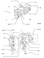
- FIG. 1 shows an elevator system 1 with a support means 2 held on the car 3, and counterweight 4, which are in a vertically extending shaft 5, opposite, movable up and down.
- a mounted below a shaft ceiling 6 drive 7 carries and drives the support means 2 and held by means of the support means 2 car 3 and counterweight. 4
- an existing elevator installation 1 with machine room 8 is provided with a new drive 7.
- the original required by the old engine 9 space is no longer needed for the new drive 7.
- the old drive machine 9 can be left in the assembled state and disassembled at a later time, or the space can be used for other tasks.
- a control 10 required for the new drive 7 can, as can be seen in the example, be arranged in the former machine room 8, or in the access area of a landing door, or at another location, preferably in the vicinity of the drive 7.
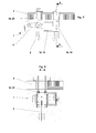
- the new drive 7 is, as in the Fig.2 and 3 shown, modular design.
- a drive module 11 is provided with a traction sheave 12 for the support means 2 of the car 3 and counterweight 4, with a motor 21 required for driving the traction sheave 12 and in the example shown with a braking device 14 required for braking the traction sheave 12.
- the drive device 13 and the traction sheave 12 are connected to a drive module 11, as in FIG Fig. 4 exemplified, assembled.
- the drive module 11 is provided with interfaces 15. These interfaces 15 allow the connection of connection parts 16. These connection parts 16 allow either a mounting of the drive module 11 within the shaft 5, for example, to the shaft ceiling 6 as in the Fig. 1 . 7 and 8 visible or on the floor of a conventional engine room 8 as in Fig. 5 represented or on the pedestals 17 a previously dismantled old prime mover 9, as in Fig. 6 shown.
- the interfaces 15 further allow the connection of an extension 18, to which a deflection module 19 is connected as in the FIGS. 1 . 2 and 3 shown.
- the extension 18 together with the drive module 11 and the deflection module 19 allows adjustment of the support means distance corresponding to the requirements of the elevator installation 1.
- the deflection module 19 contains in turn interfaces 15 which the Connection of fasteners as used in the drive module 11 allows.
- the interface 15 of the drive module 11 and the interface 15 of the deflection module are identical. This allows for easy installation, since when attaching the extension 18 there is no possibility of confusion.
- extension 18 and the deflection module 19 are designed such that the overall height of the drive 7 by the assembly of drive module 11, extension 18 and deflection module 19 is not changed.
- the interfaces 15 are designed functionally. They allow a modular composition of the drive 7 according to the requirements of the building.
- An additional advantage is that the individual modules and parts can be transported separately to the installation site.
- the transport units are small and have a low individual weight. For example, they can be transported to the vicinity of the installation site in the building by means of an old elevator installation 9 intended for conversion.
- this drive 7 is best suited for replacing existing drives 9 by being optimally adaptable to existing buildings, i. it can be arranged both within the shaft 5 as in an existing engine room 8.
- the support means distance is also easily adjustable. The setting of the support means distance does not affect the overall height of the drive 7.
- the drive module 11 is optionally provided with a guide roller 20, which ensures a, independent of the support means distance, wrap around the traction sheave 12 by the support means 2. If the suspension element 2 is deflected using the guide roller 20, the wrap angle ( ⁇ ) is 90 ° to 180 °. This wrap can be changed by the arrangement of the guide roller 20. As a rule, a wrap angle ( ⁇ ) in the vicinity of 180 ° is desired.
- the drive module 11 can also directly, without Use of the guide roller 20 are used. Depending on the arrangement, this results in a wrap angle ( ⁇ ) of 90 ° or 180 °, as in the schematic diagrams Figures Figures 4a, 4b and 4c shown.
- wrap angle ( ⁇ ) can be defined independently of the carrier mean distance.
- the drive module 11 is preferably provided with a monitoring device (not shown), which monitors the correct driving force transmission from the traction sheave 12 to the suspension element 2 and / or the correct tension of the suspension element 2.
- a monitoring device not shown
- FIG. 4 illustrated arrangement of the guide roller 20 allows control of the transmission of power by, for example, the speed of the guide roller 20 is compared with the speed of the traction sheave 12. If the two values differ noticeably from each other, there is an incorrect transmission of the driving forces.
- the advantage of this design is the fact that the correct transmission of the driving force can be monitored directly on the drive 7. As a result, the security and availability of the elevator installation 1 is increased, since case-specific the correct measures (maintenance request, shutdown, etc.) can be initialized quickly.
- the support means 2 has, as in the FIGS. 4d to 4f 12 has a substantially circular cross-section or has a substantially flat cross-section, the surface serving to transmit the driving force being smooth, longitudinal, serrated, studded, perforated or of any other structure, or the support means 2 has any cross-section ,
- the traction sheave is designed such that the transmission of the driving force from the traction sheave on the support means 2 is functionally enabled.
- the drive 7 is not limited to a specific support means 2. It is suitable for a variety of load-bearing profile shapes. It is advantageous if support means 2 are used, which are suitable for small deflection radii. As a result, the drive 7 can be made particularly small.
- the motor 21 of the drive module 11 arranged parallel axis to the traction sheave 12, wherein the motor 21 is connected by a drive belt 23 with a pulley 22 which is arranged coaxially with the drive pulley 12.
- This design requires little space in the width of the drive 7 and the transmission of the drive torque is low vibration.
- the motor 21 is arranged directly coaxial with the traction sheave 12.
- the advantage of this alternative is the fact that the overall length of the drive 7 is reduced.
- the engine 21 is connected to the transmission shaft 24 by a transmission.
- the advantage of this alternative is the use of commercially available translation devices.
- the brake device 14 is advantageously arranged directly on the traction sheave shaft 24 or the traction sheave 12 acting. This arrangement significantly reduces the risk of brake failure, as the braking force is introduced directly into the traction sheave 12.
- the advantage of this arrangement is that a safety-compliant braking system for stopping and holding a car 3 with intact support means 2 can be realized inexpensively.
- the brake device 14 is arranged to act directly on the shaft of the drive motor 21. This arrangement is inexpensive because a braking device 14 can be used with low braking torque. This arrangement usually requires further, known in the market, safety measures to catch a failure of the connection of drive motor 21 to traction sheave shaft 24.
- the brake device 14 or a further braking device may be arranged on the deflection module 19.
- the traction sheave 12 and / or a traction sheave shaft 24 and / or the pulley 22 is made in one piece. This embodiment enables a production-optimized and cost-effective design of the drive module 11.
- the drive module 11 is provided with interfaces 15, which allows the attachment of several connection parts 16.
- the advantage of this design results from the universal applicability of the drive module 11.
- the interfaces 15 allow the cultivation of the required for a particular elevator installation 1 Connecting parts 16.
- the interfaces 15 are, as in the Figures 3 . 4 . 9 and 10 can be seen, for example, slots or 1 or arrangements or jaws for receiving connection parts.
- the connection parts 16 are optionally extension 18, deflection module 19, suspension or support modules 25, 26, or suspension means end connections 27 or further aids.
- the design of the drive module 11 with functional interfaces 15 allows the use of the drive module 11 for many types of elevators, and this allows a rational and cost-effective production of the product.
- a first advantageous connection part 16 is an extension 18, which is arranged with an end region on the interface 15 of the drive module 11, and at the other end region of a deflection module 19 is attached.
- the deflection module 19 has the drive module identical interface 15.
- the advantage of the extension 18 is that an adjustment of the support means distance is possible.
- universal drive and deflection modules can be used, which in turn allows a rational production of the drive.
- the deflection module 19 and the drive module 11 have the same interfaces 15. This is particularly advantageous because it increases the design options. For example, instead of the arrangement, drive module 11 and deflection module 19, two drive modules 11 can be used. As a result, the performance of the drive system 7 can be significantly increased.
- the interface 15 of the drive module 11 and the deflection module 19 for extension 18 allows a fine adjustability of the Tragstoffdistanz.
- This advantageous embodiment allows adjustment to the actually existing carrier distance. Thus, there is no diagonal pull, whereby wear of the support means 2 is reduced.
- Another advantageous connection part 16 is a suspension module 25 which is arranged on the interface 15 of the drive module 11 and / or the deflection module 19, which allows the suspension of the drive to a shaft ceiling 6, or another connection part 16 is a support module 26, which the interface 15 of the drive module 11 and / or the Umlenkmoduls 19 is arranged, which allows the attachment of the drive 7 in a machine room 8 or on a shaft wall.
- the hanging or support modules 25,26 are advantageously provided with noise or vibration damping materials.
- the advantage of this embodiment is the fact that a building type appropriate attachment can be used.
- the suspension module 25 uses, for example, existing openings in the shaft ceiling 6, or in the bottom of the overhead engine room 8 to hang the drive 7 to the shaft ceiling 6, wherein the counterplates required in the engine room 8 are made long and narrow, and between the existing machine bases 17 are arranged.
- the counter plates may have other shapes, as they result usefully for the arrangement. For example, they can be round if required.
- the drive module 11 and / or the deflection module 19 is advantageously provided with suspension means end connections 27.
- the advantage here is that the interfaces are reduced to the building, since all supporting forces from the car 3 and counterweight 4 are performed on the drive unit 7 and are introduced via the suspension points of the drive 7 in the building.
- the arrangement of the suspensions allows the use of a 2: 1 umhlindfitten arrangement in elevator systems 1, which were hung in the old version directly, or 1: 1. This arrangement is made possible by a particularly advantageous design of Tragstoffendriven.
- the drive module 11 and / or the deflection module 19 is provided with an interface 15 for fastening an auxiliary hoist 28.
- the auxiliary hoist 28 is used for installation-related process of elevator material and / or installation personnel. This supplement allows a particularly efficient sequence of assembly of the inventive drive 7, as in the FIG. 13 exemplified.
- the drive 7 is transported by means of the old elevator installation 1 in the vicinity of the installation site and completed there with the necessary connection parts 16.
- the old cab 3 is now set and secured in the vicinity of the top stop and the old support members are dismantled.
- the drive 7 is preferably lifted using the existing cable bushings and an attached in the engine room 8 drawbar 29, to the shaft ceiling 6 and secured by means of suspension module 25.
- An auxiliary hoist 28 is now attached to, provided on the drive 7, interface 15. With the help of this auxiliary hoist 28, the cab 3 can now be moved and any components of the old engine room equipment, such as drive machine, control boxes, etc., can be transported by means of the auxiliary hoist 28.
- the new support means 2 can be retracted, the auxiliary hoist 28 can be removed and the elevator system 1 is again available to the customer after a short conversion time.
- This described conversion process is just one possible example. It shows the advantageous use of the inventive drive 7.
- a supplementary embodiment prefers that the attachment TragstoffendENS 27 is provided with a monitoring for detecting the suspension medium tension.
- suitable measures can be initialized in the event of a deviation of the suspension element tension, such as, for example, a request by a service person or a shutdown of the elevator installation 1 before an unsafe operating state arises.
- the elevator 10 associated with the control and / or drive control is advantageously arranged in the engine room 8. Alternatively, it can also be arranged wholly or partly in the shaft 5 or in an easily accessible location, preferably in the vicinity of the drive.
- a machine room 8 When converting existing elevator systems 1 a machine room 8 is often available.
- the engine room 8 can not be used otherwise as a rule.
- a use of the machine room 8 for the arrangement of the new controller 10 and / or drive control offers.
- the electrical connection to the drive 7 is usually possible simply by existing openings in the shaft ceiling 6. It is particularly advantageous that an existing engine room 8 is used meaningful.
- the best arrangement of the controller 10 and / or the drive control can be selected.
Landscapes
- Engineering & Computer Science (AREA)
- Civil Engineering (AREA)
- Mechanical Engineering (AREA)
- Structural Engineering (AREA)
- Lift-Guide Devices, And Elevator Ropes And Cables (AREA)
- Cage And Drive Apparatuses For Elevators (AREA)
Abstract
Die Erfindung betrifft eine Aufzugsanlage mit einem Antrieb (7), mit Kabine (3) und einem Gegengewicht (4), welcher Antrieb (7) mit mindestens einer Treibscheibe (12), mit mindestens einem zum Treiben der Treibscheibe (12) erforderlichen Motor (21) und mit einem Umlenkmodul (19) versehen ist. Der Motor (21) und die Treibscheibe (12) sind zu einem Antriebsmodul (11) zusammengebaut. Das Antriebsmodul (11) und / oder das Umlenkmodul (19) ist ferner mit Aufhängungen zur Befestigung einer Tragmittelendbefestigung (27) versehen.The invention relates to an elevator installation with a drive (7), with cabin (3) and a counterweight (4), which drive (7) with at least one traction sheave (12), with at least one motor (2) required for driving the traction sheave (12). 21) and with a deflection module (19) is provided. The motor (21) and the traction sheave (12) are assembled to a drive module (11). The drive module (11) and / or the deflection module (19) is further provided with suspensions for fastening a Tragmittelendbefestigung (27).
Description
Die Erfindung betrifft eine Aufzugsanlage mit einem modularen Antrieb gemäß dem Oberbegriff des unabhängigen Patentanspruchs.The invention relates to an elevator system with a modular drive according to the preamble of the independent claim.
Eine Aufzugsanlage bezweckt den Transport von Personen und Gütern innerhalb eines Gebäudes zwischen Stockwerken. Eine Kabine dient zur Aufnahme der Personen und Güter.An elevator system aims to transport people and goods within a building between floors. A cabin serves to accommodate the people and goods.
Ein Antrieb treibt mittels Tragmittel die Kabine, die dadurch in einem sich vertikal erstreckenden Schacht auf und ab verfahren wird. Das Tragmittel verbindet die Kabine mit einem Gegengewicht. Es ist dabei über eine Treibscheibe geführt. Die Treibscheibe überträgt die zum Verfahren oder zum Halten erforderliche Kraft auf die Tragmittel. Die Treibscheibe wird dazu von einer Antriebsvorrichtung und / oder von einer Bremsvorrichtung getrieben oder gehalten.A drive drives by means of suspension the cabin, which is thereby moved up and down in a vertically extending shaft. The suspension element connects the cabin to a counterweight. It is guided by a traction sheave. The traction sheave transmits the force required for the process or the holding to the suspension elements. The traction sheave is driven or held by a drive device and / or by a braking device.
Ein anderer Antriebstyp treibt die Kabine mittels hydraulischen Hubgeräten. Die Treib- und Haltekraft wird dabei von einem Pumpenaggregat direkt über einen Kolben wirkend, oder indirekt mittels einem Seil- oder Kettenzug wirkend, auf die Kabine übertragen.Another type of drive drives the cabin by means of hydraulic lifting devices. The driving and holding force is acting by a pump unit directly via a piston acting, or indirectly by means of a rope or chain hoist, transmitted to the cabin.
Beide Antriebstypen weisen spezifische Nutzungseigenschaften auf, zudem sind sie Verschleiß unterworfen. Die Nutzungseigenschaften sind beispielsweise die Fahrgeschwindigkeit oder die Traglast für die die Aufzugsanlage ausgelegt ist. Verschleiß entsteht beispielsweise durch eine längerdauernde Benutzung der Aufzugsanlage, welches zu Abnutzungserscheinungen an Bauteilen der Aufzugsanlage führt. Ändern sich die Nutzungsanforderungen oder wird der Verschleiß zu groß muss der Antrieb oder allenfalls die gesamte Aufzugsanlage ersetzt oder erneuert werden.Both drive types have specific usage characteristics and are subject to wear. The usage characteristics are, for example, the driving speed or the load for which the elevator installation is designed. Wear arises, for example, by prolonged use of the elevator system, which leads to signs of wear on components of the elevator installation. If the usage requirements change or the wear becomes too great, the drive or at least the entire elevator system must be replaced or replaced.
Um ein möglichst weites Anwendungsfeld beim Ersatz bestehender Aufzugsantriebe oder gesamter Aufzugsanlagen mit wenigen Komponenten abzudecken sind universell oder modular einsetzbare Antriebsmaschinen erforderlich.In order to cover the widest possible field of application when replacing existing elevator drives or entire elevator systems with a few components, universal or modular drive machines are required.
Aus bestehenden Schriften sind Antriebe bekannt, welche klein und kompakt sind, oder veränderbare Tragmittel-Abgriffe ermöglichen.From existing writings drives are known which are small and compact, or allow variable support means taps.
So zeigt
Aus
Aufgabe der Erfindung ist es nun einen Antrieb für eine Aufzugsanlage bereitzustellen welche für den Ersatz bestehender Antriebe geeignet ist, der optimal auf bestehende Gebäude adaptierbar ist, d.h. dass er soll ohne weitere baulichen Maßnahmen in einem bestehenden Maschinenraum oder innerhalb des Schachtraumes angeordnet werden können. Der Tragmittelabstand soll einfach einstellbar sein und der Antrieb soll geringe Abmessungen aufweisen.The object of the invention is now to provide a drive for an elevator installation which is suitable for the replacement of existing drives, which is optimally adaptable to existing buildings, i. that it should be able to be arranged without further structural measures in an existing engine room or within the shaft space. The support means distance should be easily adjustable and the drive should have small dimensions.
Im weiteren soll der Antrieb für umgehängte Aufzugsanlagen wie für direkt, 1:1 gehängte Aufzugsanlagen verwendbar sein. Selbstverständlich sind generelle Aspekte wie hoher Sicherheitsstandard, wirtschaftliche Herstellung und Montage mitzuberücksichtigen.In addition, the drive for suspended elevator systems as for directly, 1: 1 hung elevator systems should be used. Of course, general aspects such as high safety standards, economic production and assembly must be taken into account.
Die im unabhängigen Patentanspruch definierte Lösung erfüllt diese Aufgaben.The solution defined in the independent claim fulfills these tasks.
Die Aufzugsanlage beinhaltet einem Antrieb, eine an Tragmitteln gehaltene Kabine und ein Gegengewicht. Die Kabine und das Gegengewicht sind in einem sich vertikal erstreckenden Schacht entgegengerichtet auf und ab verfahrbar angeordnet. Das Tragmittel verbindet die Kabine mit dem Gegengewicht und das Tragmittel wird vom Antrieb mittels mindestens einer Treibscheibe getragen und getrieben. Der Antrieb ist mit der Treibscheibe, mit mindestens einem zum Treiben der Treibscheibe erforderlichen Motor und mit einem Umlenkmodul versehen. Der Motor und die Treibscheibe sind zu einem Antriebsmodul zusammengebaut. Die Kernfunktion des Antriebes wird durch dieses Antriebsmodul wahrgenommen. In der Regel enthält das Antriebsmodul ebenfalls eine Bremsvorrichtung.The elevator installation includes a drive, a carousel and a counterweight. The car and the counterweight are arranged in a vertically extending shaft oppositely arranged up and down movable. The support means connects the car with the counterweight and the support means is carried and driven by the drive by means of at least one traction sheave. The drive is provided with the traction sheave, with at least one motor required for driving the traction sheave and with a deflection module. The motor and the traction sheave are assembled into a drive module. The core function of the drive is perceived by this drive module. In general, the drive module also includes a braking device.
Gemäß der Erfindung ist das Antriebsmodul und / oder das Umlenkmodul mit Aufhängungen zur Befestigung einer Tragmittelendbefestigung versehen.According to the invention, the drive module and / or the deflection module is provided with suspensions for fastening a Tragmittelendbefestigung.
Des Weiteren können das Antriebsmodul und das Umlenkmodul mittels einer Verlängerung miteinander verbunden, sein.Furthermore, the drive module and the deflection module can be connected to one another by means of an extension.
Ferner können das Antriebsmodul und das Umlenkmodul mit identischen Schnittstellen versehen sein, welche zusammen mit der Verlängerung eine Anpassung des Antriebes an eine erforderliche Tragmitteldistanz ermöglichen.Furthermore, the drive module and the deflection module can be provided with identical interfaces which, together with the extension, make it possible to adapt the drive to a required carrier distance.
Zudem kann das Antriebsmodul und / oder das Umlenkmodul mit Anschlussteilen versehen sein, welche zur Befestigung des Antriebs innerhalb des Schachtes oder im Maschinenraum verwendet werden.In addition, the drive module and / or the deflection module can be provided with connection parts which are used for fastening the drive within the shaft or in the engine room.
Mit dieser Lösung ist der der Antrieb in optimaler Weise für bestehende Gebäude adaptierbar und er kann - unter Verwendung der Anschlussteile - ohne weitere bauliche Maßnahmen in einem bestehenden Maschinenraum oder innerhalb eines Schachtes angeordnet werden. Der Tragmittelabstand kann unter Verwendung der Verlängerung und der Schnittstellen an Antriebs- und Umlenkmodul einfach an vorgegebene Tragseildistanzen angepasst werden. Der modulare Aufbau von Antriebsmodul und Umlenkmodul sowie deren Befestigungsmöglichkeit mittels eigener Anschlussteile ermöglicht geringe Abmessungen, da Tragkräfte direkt in das Gebäude eingeleitet werden.With this solution, the drive can be optimally adapted to existing buildings and it can - using the connecting parts - be arranged without further structural measures in an existing machine room or within a shaft. The support means distance can be easily adapted to predetermined Tragseildistanzen using the extension and the interfaces to drive and deflection module. The modular design of the drive module and deflection module as well as their ability to be fastened by means of their own connection parts allows small dimensions, as load-bearing forces are introduced directly into the building.
Die Anschlussteile sind entsprechend den Gebäudeanforderungen gestaltet. Das Antriebsmodul und das Umlenkmodul weisen die entsprechenden Schnittstellen auf. Die Teile werden dadurch rationell und in großen Stückzahlen herstellbar. Dies ergibt wirtschaftlich optimale Herstellbedingungen. Durch die Aufteilung auf Module und Teile wird der Antrieb leicht transportierbar, er kann beispielsweise, innerhalb eines bestehenden Gebäudes, mit einer bestehenden Aufzugsanlage in die Nähe des Montageortes transportiert werden. Er ist damit hervorragend für den Umbau von Aufzugsanlagen in bestehenden Gebäuden geeignet.The connection parts are designed according to the building requirements. The drive module and the deflection module have the corresponding interfaces. The parts are thus produced efficiently and in large quantities. This results in economically optimal production conditions. By dividing it into modules and parts, the drive can be easily transported; for example, within an existing building, it can be transported with an existing elevator system close to the installation site. It is thus ideally suited for the conversion of elevator systems in existing buildings.
Vorteilhaft wirkt sich ebenfalls aus, dass die Einbauhöhe des Antriebes, unabhängig vom Tragmittelabstand, nicht verändert wird, und damit keine Abhängigkeit des Höhen-Platzbedarfes von dem Tragmittelabstand besteht.Another advantage is also that the installation height of the drive, regardless of the support means distance, is not changed, and thus there is no dependence of the height space requirement of the support means distance.
Weitere Vorteilhafte Lösungen sind in den abhängigen Ansprüchen beschrieben.Further advantageous solutions are described in the dependent claims.
In einer vorteilhaften Weiterbildung ist das Antriebsmodul mit einer Führungsrolle versehen. Die Führungsrolle ist im Antriebsmodul derart platziert, dass sie, unabhängig von der Tragmitteldistanz, eine fest definierte Umschlingung der Treibscheibe ermöglicht. Dadurch entfallen aufwendige anlagebezogene Nachweise der genügenden Treibfähigkeit, da für die Nachweisrechnung wenige festdefinierte Umschlingungswinkel berücksichtigt werden können. Das Antriebsmodul kann dadurch besonders wirtschaftlich hergestellt werden.In an advantageous development, the drive module is provided with a guide roller. The guide roller is placed in the drive module such that it allows, regardless of the Tragmitteldistanz, a tightly defined looping of the traction sheave. This eliminates complex investment-related evidence of sufficient traction, as for the verification calculation few fixed-wrap can be considered. The drive module can be produced thereby particularly economically.
In das Antriebsmodul und / oder das Umlenkmodul ist eine Befestigung zur Befestigung von Tragmittelenden integriert. Diese Befestigung wird bei umgehängten Aufzugsanlagen vorteilhaft verwendet. Sämtliche maßgebenden Tragstellen des Antriebes sind damit im Antrieb selbst platziert. Durch die vom Antrieb vorgegebenen Tragstellen wird die gesamte Aufhängekraft der Aufzugsanlage aufgenommen. Die Antriebsmaschine ist damit hervorragend für die Anwendung in bestehenden Gebäuden geeignet, da die Einleitung der Kräfte im Gebäude auf wenige Stellen reduziert wird.In the drive module and / or the deflection module a fastening for attachment of Tragmittelenden is integrated. This attachment is advantageously used in suspended elevator systems. All authoritative support points of the drive are thus placed in the drive itself. By the predetermined by the drive support points the entire suspension of the elevator system is added. The prime mover is therefore ideally suited for use in existing buildings, as the introduction of forces in the building is reduced to a few places.
Im Antriebsmodul ist vorteilhafterweise eine Überwachungseinrichtung angeordnet, welche die korrekte Übertragung der Treibkräfte auf die Treibmittel überwacht. Eine ungenügende Übertragung der Treibkräfte wird beispielsweise festgestellt, indem die Drehzahl der Führungsrolle mit der Drehzahl der Treibscheibe verglichen wird. Bei maßgebender Abweichung werden vordefinierte Sicherheitsmaßnahmen eingeleitet. Dadurch wird die Sicherheit und Verfügbarkeit der Aufzugsanlage erhöht, da fallspezifisch die richtigen Maßnahmen (Wartungsanforderung, Stillsetzung, etc.) initialisiert werden können.In the drive module, a monitoring device is advantageously arranged, which monitors the correct transmission of the driving forces to the propellant. A insufficient transmission of the driving forces is determined, for example, by comparing the rotational speed of the guide roller with the rotational speed of the traction sheave. In case of decisive deviation, predefined security measures are initiated. As a result, the safety and availability of the elevator system is increased because the correct measures (maintenance request, shutdown, etc.) can be initialized case-specifically.
In einer vorteilhaften Ausgestaltung der Aufzugsanlage weist diese einen Antrieb, eine Kabine und ein Gegengewicht auf. Der Antrieb ist mit mindestens einer Treibscheibe, mit mindestens einem zum Treiben der Treibscheibe erforderlichen Motor und mit einem Umlenkmodul versehen, wobei der Motor und die Treibscheibe zu einem Antriebsmodul zusammengebaut sind. Ferner sind das Antriebsmodul und das Umlenkmodul mittels einer Verlängerung miteinander verbunden und das Antriebsmodul und das Umlenkmodul sind mit identischen Schnittstellen versehen, welche zusammen mit der Verlängerung eine Anpassung des Antriebs an eine erforderliche Tragmitteldistanz ermöglichen. Zudem sind das Antriebsmodul und / oder das Umlenkmodul mit Anschlussteilen versehen, welche zur Befestigung des Antriebs innerhalb des Schachtes oder im Maschinenraum verwendet sind.In an advantageous embodiment of the elevator system, this has a drive, a cabin and a counterweight. The drive is provided with at least one traction sheave, with at least one motor required for driving the traction sheave and with a deflection module, wherein the motor and the traction sheave are assembled to form a drive module. Furthermore, the drive module and the deflection module are connected to one another by means of an extension, and the drive module and the deflection module are provided with identical interfaces which, together with the extension, make it possible to adapt the drive to a required carrier distance. In addition, the drive module and / or the deflection module are provided with connection parts which are used for fastening the drive within the shaft or in the engine room.
In dieser Aufzugsanlage kann der Motor parallelachsig zur Treibscheibe angeordnet sein und durch einen Treibriemen mit einer Riemenscheibe verbunden sein, die koaxial zur Treibscheibe angeordnet ist, oder
der Motor kann direkt koaxial zur Treibscheibe angeordnet sein, oder der Motor kann mittels eines Getriebes mit einer Treibscheibenwelle verbunden sein, die koaxial zur Treibscheibe angeordnet ist.In this elevator system, the motor may be arranged parallel-axis to the traction sheave and be connected by a drive belt with a pulley, which is arranged coaxially with the traction sheave, or
the motor may be arranged directly coaxial with the traction sheave, or the motor may be connected by means of a gear mechanism to a traction sheave shaft arranged coaxially with the traction sheave.
Das Anschlussteil kann ein Tragmodul sein, welches an der Schnittstelle des Antriebsmoduls und / oder des Umlenkmoduls angeordnet ist, welches zur Befestigung des Antriebes in einem Maschineraum oder an einer Schachtwand verwendet ist.The connection part may be a support module, which is arranged at the interface of the drive module and / or the deflection module, which is used for fastening the drive in a machine room or on a shaft wall.
Das Anschlussteil kann auch ein Hängemodul sein, welches an der Schnittstelle des Antriebsmoduls und / oder des Umlenkmoduls angeordnet ist, welches zur Aufhängung des Antriebes an einer Schachtdecke verwendet wird, wobei das Hängemodul unter Benutzung bestehender Öffnungen in der Schachtdecke, bzw. im Boden des obenliegenden Maschinenraumes, an die Schachtdecke gehängt wird. Die dazu im Maschinenraum erforderlichen Gegenplatten sind lang und schmal ausgeführt oder von beliebiger Form und zwischen bestehenden Maschinensockeln angeordnet.The connection part may also be a suspension module, which is arranged at the interface of the drive module and / or the deflection module, which is used for suspending the drive on a shaft ceiling, wherein the suspension module using existing openings in the shaft ceiling, or in the bottom of the overhead engine room, to the shaft ceiling is hung. The required counterparts in the engine room are made long and narrow or arranged of any shape and between existing machine bases.
Des weiteren kann das Antriebsmodul und / oder das Umlenkmodul mit Aufhängungen zur Befestigung eines Hilfshebezeug versehen sein
und /oder das Antriebsmodul und / oder das Umlenkmodul mit Aufhängungen zur Befestigung einer Tragmittelendbefestigung versehen sein.Furthermore, the drive module and / or the deflection module can be provided with suspensions for fastening an auxiliary hoist
and / or the drive module and / or the deflection module are provided with suspensions for fastening a Tragmittelendbefestigung.
Die zur Aufzugsanlage zugehörende Steuerung und Antriebsregelung kann im Maschinenraum, im Schacht oder an einem anderen Ort angeordnet sein.The belonging to the elevator system control and drive control can be arranged in the engine room, in the shaft or at another location.
Ein mögliches Verfahren zum Umbau bestehender Aufzugsanlagen mittels einem Antrieb für eine Aufzugsanlage sieht vor, dass der Antrieb mit mindestens einer Treibscheibe und mit einem zum Treiben der Treibscheibe erforderlichen Motor versehen ist, wobei der Motor und die Treibscheibe zu einem Antriebsmodul zusammengebaut sind. Das Antriebsmodul und das Umlenkmodul werden mittels einer Verlängerung miteinander verbunden. Das Antriebsmodul und das Umlenkmodul sind mit identischen Schnittstellen versehen, welche zusammen mit der Verlängerung eine Anpassung des Antriebs an eine erforderliche Tragmitteldistanz ermöglichen. Das Antriebsmodul und / oder das Umlenkmodul sind mit Anschlussteilen versehen, welche zur Befestigung des Antriebs innerhalb des Schachtes oder im Maschinenraum verwendet werden, wobei der Antrieb in einzelnen Modulen oder Teilen in die Nähe des Installationsortes gebracht wird und dort zum gesamten Antrieb zusammengebaut wird.One possible method for converting existing elevator systems by means of a drive for an elevator installation provides that the drive is provided with at least one traction sheave and with a motor required for driving the traction sheave, the motor and the traction sheave being assembled to form a drive module. The drive module and the deflection module are connected to each other by means of an extension. The drive module and the deflection module are provided with identical interfaces which, together with the extension, allow adaptation of the drive to a required carrier distance. The drive module and / or the deflection module are provided with connection parts, which are used for fastening the drive within the shaft or in the engine room, wherein the drive is brought in individual modules or parts in the vicinity of the installation site and assembled there to the entire drive.
In den folgenden
- Figur 1:
- Beispiel einer Aufzugsanlage mit einem erfindungsgemässen modularen Antrieb, zur möglichen Anwendung bei einem Umbau;
- Figur 2:
- eine 3-dimensionale Ansicht eines modularen Antriebes;
- Figur 3:
- eine weitere 3-dimensionale Ansicht eines modularen Antriebes;
- Figur 4:
- eine 3-dimensionale Ansicht eines Antriebsmoduls;
- Figuren 4a bis 4c:
- Umschlingungsbeispiele;
- Figuren 4d bis 4f:
- beispielhafte Tragmittelausführungen;
- Figur 5:
- ein erstes Installationsbeispiel eines modularen Antriebs montiert auf einer Schachtdecke;
- Figur 6:
- ein zweites Installationsbeispiel eines modularen Antriebs montiert auf einer Schachtdecke;
- Figur 7:
- ein drittes Installationsbeispiel eines modularen Antriebs montiert unterhalb einer Schachtdecke;
- Figur 8:
- eine Seitenansicht eines modularen Antriebs montiert unterhalb einer Schachtdecke;
- Figur 9:
- ein Beispiel eines Umlenkmoduls;
- Figur 10:
- ein Beispiel eines Umlenkmoduls mit Verlängerungen;
- Figur 11:
- eine Querschnittsdarstellung eines Antriebsmoduls mit Riemenverbindung;
- Figur 12:
- eine Querschnittsdarstellung eines Antriebsmoduls mit direktverbundener Antriebsvorrichtung und
- Fig. 13:
- Darstellung eines Montageverfahrens.
- FIG. 1:
- Example of an elevator installation with a modular drive according to the invention, for possible use in a conversion;
- FIG. 2:
- a 3-dimensional view of a modular drive;
- FIG. 3:
- another 3-dimensional view of a modular drive;
- FIG. 4:
- a 3-dimensional view of a drive module;
- FIGS. 4a to 4c:
- Umschlingungsbeispiele;
- FIGS. 4d to 4f:
- exemplary support means executions;
- FIG. 5:
- a first installation example of a modular drive mounted on a shaft ceiling;
- FIG. 6:
- a second installation example of a modular drive mounted on a shaft ceiling;
- FIG. 7:
- a third installation example of a modular drive mounted below a shaft ceiling;
- FIG. 8:
- a side view of a modular drive mounted below a shaft ceiling;
- FIG. 9:
- an example of a deflection module;
- FIG. 10:
- an example of a deflection module with extensions;
- FIG. 11:
- a cross-sectional view of a drive module with belt connection;
- FIG. 12:
- a cross-sectional view of a drive module with directly connected drive device and
- Fig. 13:
- Presentation of an assembly process.
Ein unterhalb einer Schachtdecke 6 angebrachter Antrieb 7 trägt und treibt die Tragmittel 2 und die mittels der Tragmittel 2 gehaltene Kabine 3 und Gegengewicht 4.A mounted below a
Im gezeigten Beispiel ist eine bestehende Aufzugsanlage 1 mit Maschinenraum 8 mit einem neuen Antrieb 7 versehen. Der ursprüngliche von der alten Antriebsmaschine 9 benötigte Raum wird für den neuen Antrieb 7 nicht mehr benötigt. Die alte Antriebsmaschine 9 kann, wie im Beispiel gezeigt, in montiertem Zustand belassen werden und zu einem späteren Zeitpunkt demontiert werden, oder der Raum kann für andere Aufgaben verwendet werden.In the example shown, an existing
Eine für den neuen Antrieb 7 benötigte Steuerung 10 kann, wie im Beispiel erkennbar, im ehemaligen Maschinenraum 8, oder im Zugriffsbereich einer Etagentüre, oder an einer anderen Stelle, vorzugsweise in der Nähe des Antriebes 7, angeordnet sein.A
Der neue Antrieb 7 ist, wie in den
Erfindungsgemäß ist das Antriebsmodul 11 mit Schnittstellen 15 versehen. Diese Schnittstellen 15 ermöglichen den Anschluss von Anschlussteilen 16. Diese Anschlussteile 16 ermöglichen wahlweise eine Befestigung des Antriebsmoduls 11 innerhalb des Schachtes 5 beispielsweise an die Schachtdecke 6 wie in den
Die Schnittstellen 15 ermöglichen im Weiteren den Anschluss einer Verlängerung 18, an welche ein Umlenkmodul 19 angeschlossen ist wie in den
Vorzugsweise sind die Schnittstelle 15 des Antriebsmoduls 11 und die Schnittstelle 15 des Umlenkmoduls identisch ausgeführt. Dies ermöglicht eine einfache Montage, da beim Anbringen der Verlängerung 18 keine Verwechslungsmöglichkeit besteht.Preferably, the
Die Verlängerung 18 und das Umlenkmodul 19 sind derart ausgeführt, dass die Bauhöhe des Antriebes 7 durch den Zusammenbau von Antriebsmodul 11, Verlängerung 18 und Umlenkmodul 19 nicht verändert wird.The
Die Schnittstellen 15 sind funktionsgerecht gestaltet. Sie ermöglichen eine modulare Zusammensetzung des Antriebes 7 nach den Erfordernissen des Gebäudes.The
Als Vorteil ergibt sich zusätzlich, dass die einzelnen Module und Teile separat zum Montageort transportiert werden können. Dadurch sind die Transporteinheiten klein und weisen ein geringes Einzelgewicht auf. Sie können beispielsweise mit einer alten, zum Umbau vorgesehenen Aufzugsanlage 9 in die Nähe des Installationsortes im Gebäude transportiert werden.An additional advantage is that the individual modules and parts can be transported separately to the installation site. As a result, the transport units are small and have a low individual weight. For example, they can be transported to the vicinity of the installation site in the building by means of an
Der Vorteil dieser Erfindung ist darin zu erkennen, dass dieser Antrieb 7 zum Ersatz bestehender Antriebe 9 bestens geeignet ist, indem er optimal auf bestehende Gebäude adaptierbar ist, d.h. er kann sowohl innerhalb des Schachtes 5 wie in einem bestehenden Maschinenraum 8 angeordnet werden. Der Tragmittelabstand ist zudem einfach einstellbar. Die Einstellung des Tragmittelabstandes beeinflusst die Bauhöhe des Antriebes 7 nicht.The advantage of this invention can be seen in the fact that this
Wie in
Der Vorteil dieser Anordnung ist darin zu erkennen, dass der Umschlingungswinkel(β) unabhängig von der Tragmitteldistanz definiert werden kann.The advantage of this arrangement can be seen in that the wrap angle (β) can be defined independently of the carrier mean distance.
Das Antriebsmodul 11 ist vorzugsweise mit einer Überwachungseinrichtung (nicht dargestellt) versehen, welche die korrekte Treibkraftübertragung von der Treibscheibe 12 zum Tragmittel 2 und / oder die korrekte Spannung der Tragmittel 2 überwacht. Die in
Der Vorteil dieser Ausführung ist darin zu sehen, dass die korrekte Übertragung der Treibkraft direkt am Antrieb 7 überwacht werden kann. Dadurch wird die Sicherheit und Verfügbarkeit der Aufzugsanlage 1 erhöht, da fallspezifisch die richtigen Maßnahmen (Wartungsanforderung, Stillsetzung, etc.) schnell initialisiert werden können.The advantage of this design is the fact that the correct transmission of the driving force can be monitored directly on the
Das Tragmittel 2 weist, wie in den
Der Antrieb 7 ist nicht auf ein bestimmtes Tragmittel 2 begrenzt. Er eignet sich für eine Vielzahl von Tragprofilformen. Es ist vorteilhaft, wenn Tragmittel 2 verwendet werden, welche sich für kleine Umlenkradien eignen. Dadurch kann der Antrieb 7 besonders klein ausgeführt werden.The
In einer vorteilhaften Ausgestaltung des erfindungsgemässen Antriebes 7 ist, wie in
Alternativ ist der Motor 21 direkt koaxial zur Treibscheibe 12 angeordnet. Der Vorteil dieser Alternative ist darin zu sehen, dass die Baulänge des Antriebes 7 reduziert ist.Alternatively, the
Bei einer weiteren Alternative ist der Motor 21 mit einem Getriebe mit der Treibscheibenwelle 24 verbunden. Der Vorteil dieser Alternative liegt in der Verwendung von marktüblichen Übersetzungseinrichtungen.In a further alternative, the
Wie in den
Vorteilhafterweise ist die Treibscheibe 12 und / oder eine Treibscheibenwelle 24 und / oder die Riemenscheibe 22 einstückig ausgeführt. Diese Ausführung ermöglicht eine Herstellungsoptimierte und kostengünstige Ausführung des Antriebsmoduls 11.Advantageously, the
Das Antriebsmodul 11 ist mit Schnittstellen 15 versehen, welche den Anbau von mehreren Anschlussteilen 16 ermöglicht. Der Vorteil dieser Ausführung ergibt sich aus der universellen Anwendbarkeit des Antriebsmoduls 11. Die Schnittstellen 15 ermöglichen den Anbau der für eine bestimmte Aufzugsanlage 1 geforderten Anschlussteile 16.The
Die Schnittstellen 15 sind, wie in den
Ein erstes vorteilhaftes Anschlussteil 16 ist eine Verlängerung 18, welche mit einem Endbereich an der Schnittstelle 15 des Antriebsmoduls 11 angeordnet ist, und an deren anderem Endbereich ein Umlenkmodul 19 befestigt ist. Das Umlenkmodul 19 weist zum Antriebsmodul identische Schnittstell 15 auf. Mittels der Verlängerung 18 und der Gestaltung der Schnittstell 15 zum Antriebs- und Umlenkmodul ist eine Anpassung des Antriebes 7 an die erforderliche Tragmitteldistanz ermöglicht. Bestehende Aufzugsanlagen 1 weisen eine bestimmte Aufhängeform der Kabine 3 bzw. des Gegengewichtes 4 auf. Aus dieser Aufhängeform ergibt sich ein charakterisierender Abstand des Tragmittelstranges, der sich in der Regel von der Mitte der Kabine 3, in der vertikalen Projektion, bis zur Mitte des Gegengewichtes 4 erstreckt.A first
Der Vorteil der Verlängerung 18 ist, dass eine Einstellung des Tragmittelabstandes möglich ist. Damit können universelle Antriebs- und Umlenkmodule verwendet werden, was wiederum eine rationelle Herstellung des Antriebes ermöglicht. Das Umlenkmodul 19 und das Antriebsmodul 11 weisen gleiche Schnittstellen 15 auf. Dies ist besonders vorteilhaft, da dadurch die Gestaltungsmöglichkeiten zunehmen. So können beispielsweise anstelle der Anordnung, Antriebsmodul 11 und Umlenkmodul 19, zwei Antriebsmodule 11 verwendet werden. Dadurch lässt sich die Leistung des Antriebsystems 7 deutlich steigern.The advantage of the
Die Schnittstelle 15 des Antriebsmoduls 11 und des Umlenkmoduls 19 zur Verlängerung 18 ermöglicht eine Fein-Einstellbarkeit der Tragmitteldistanz. Diese vorteilhafte Ausführung erlaubt eine Einstellung auf die tatsächlich vorhandene Tragmitteldistanz. Es ergibt sich somit kein Schrägzug, wodurch ein Verschleiß der Tragmittel 2 reduziert wird. Ein weiteres vorteilhaftes Anschlussteil 16 ist ein Hängemodul 25, welches an der Schnittstelle 15 des Antriebsmoduls 11 und / oder des Umlenkmoduls 19 angeordnet ist, welches die Aufhängung des Antriebes an eine Schachtdecke 6 ermöglicht, oder ein anderes Anschlussteil 16 ist ein Tragmodul 26, welches an der Schnittstelle 15 des Antriebsmoduls 11 und / oder des Umlenkmoduls 19 angeordnet ist, welches die Befestigung des Antriebes 7 in einem Maschineraum 8 oder an einer Schachtwand ermöglicht. Die Hänge- oder Tragmodule 25,26 sind vorteilhafterweise mit geräusch- oder vibrationsdämpfenden Materialien versehen. Der Vorteil dieser Ausführung ist darin zu sehen, dass eine dem Gebäudetyp entsprechende Befestigung eingesetzt werden kann.The
Das Hängemodul 25 benutzt beispielsweise bestehende Öffnungen in der Schachtdecke 6, bzw. im Boden des obenliegenden Maschinenraumes 8, um den Antrieb 7 an die Schachtdecke 6 zu hängen, wobei die im Maschinenraum 8 erforderlichen Gegenplatten lang und schmal ausgeführt sind, und zwischen den bestehenden Maschinensockeln 17 angeordnet sind. In Abhängigkeit der Ausführung des Maschinenraumes 8 können die Gegenplatten andere Formen aufweisen, wie sie sich für die Anordnung sinnvollerweise ergeben. Sie können im Bedarfsfalle beispielsweise rund ausgeführt sein.The
Besonders vorteilhaft bei dieser Ausführung ist, dass allfällige Maschinensockel 17, welche zur Befestigung eines alten Antriebes 9 verwendet wurden, belassen werden können. Dies reduziert die Umbauzeit und die damit verbundenen Kosten.Particularly advantageous in this embodiment is that any
Das Antriebsmodul 11 und / oder das Umlenkmodul 19 ist vorteilhafterweise mit Tragmittelendverbindungen 27 versehen. Von Vorteil ist dabei, dass die Schnittstellen zum Gebäude reduziert werden, da alle tragenden Kräfte aus Kabine 3 und Gegengewicht 4 auf die Antriebseinheit 7 geführt sind und über die Aufhängepunkte des Antriebes 7 in das Gebäude eingeleitet werden.The
Die Anordnung der Aufhängungen ermöglicht die Verwendung einer 2:1 umgehängten Anordnung bei Aufzugsanlagen 1, welche in der alten Ausführung direkt, bzw. 1:1 aufgehängt waren. Diese Anordnung wird durch eine besonders vorteilhafte Gestaltung der Tragmittelendverbindungen ermöglicht.The arrangement of the suspensions allows the use of a 2: 1 umhängängten arrangement in
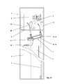
In einer sinnvollen Ergänzung ist das Antriebsmodul 11 und / oder das Umlenkmodul 19 mit Schnittstelle 15 zur Befestigung eines Hilfshebezeug 28 versehen. Das Hilfshebezeug 28 dient zum montagebedingten Verfahren von Aufzugsmaterial und / oder Montagepersonal. Diese Ergänzung erlaubt einen besonders effizienten Ablauf der Montage des erfindungsgemässen Antriebes 7, wie in der
Der Antrieb 7 wird mit Hilfe der alten Aufzugsanlage 1 in die Nähe des Installationsortes transportiert und dort mit den notwendigen Anschlussteilen 16 komplettiert. Die alte Kabine 3 wird nun in der Nähe des obersten Haltes festgesetzt und gesichert und die alten Tragorgane werden demontiert. Nun wird der Antrieb 7 vorzugsweise unter Verwendung der bereits bestehenden Seildurchführungen und einer im Maschinenraum 8 angebrachten Zugeinrichtung 29, an die Schachtdecke 6 gehoben und mittels Hängemodul 25 befestigt. Ein Hilfshebezeug 28 wird jetzt an, am Antrieb 7 vorgesehener, Schnittstelle 15 angebracht. Mit Hilfe dieses Hilfshebezeuges 28 kann nun die Kabine 3 bewegt werden und allfällige Bestandteile der alten Maschinenraumausstattung, wie Antriebsmaschine, Steuerkästen, etc. können mit Hilfe des Hilfshebezeuges 28 transportiert werden. Ist die Erneuerung der übrigen Schachtausrüstung, je nach Umbauvereinbarung ersetzt, können die neuen Tragmittel 2 eingezogen werden, das Hilfshebezeug 28 kann entfernt werden und die Aufzugsanlage 1 ist nach kurzer Umbauzeit wiederum für den Kunden verfügbar. Dieser geschilderte Umbauablauf ist lediglich ein mögliches Beispiel. Es zeigt die vorteilhafte Verwendung des erfindungsgemässen Antriebes 7 auf.The
Eine ergänzende Ausführung zieht vor, dass die Befestigung Tragmittelendverbindung 27 mit einer Überwachung zur Feststellung der Tragmittelspannung versehen ist. Der Vorteil dieser Ausführung ist, dass bei einer Abweichung der Tragmittelspannung geeignete Maßnahmen initialisiert werden können wie beispielsweise eine Anforderung eines Servicefachmannes oder ein Stillsetzen der Aufzugsanlage 1, bevor ein unsicherer Betriebszustand entsteht.A supplementary embodiment prefers that the
Die zum Aufzug zugehörende Steuerung 10 und/oder Antriebsregelung ist vorteilhafterweise im Maschinenraum 8 angeordnet. Alternativ kann sie auch ganz oder teilweise im Schacht 5 oder an einem gut zugänglichen Ort, vorzugsweise in der Nähe des Antriebes, angeordnet werden.The
Beim Umbau bestehender Aufzugsanlagen 1 ist vielfach ein Maschinenraum 8 vorhanden. Der Maschinenraum 8 kann in der Regel nicht anderweitig verwendet werden. Somit bietet sich eine Verwendung des Maschinenraumes 8 zur Anordnung der neuen Steuerung 10 und / oder Antriebsregelung an. Die elektrische Verbindung zum Antrieb 7 ist in der Regel einfach durch bestehende Durchbrüche in der Schachtdecke 6 möglich. Besonders vorteilhaft ist dabei, dass ein bestehender Maschinenraum 8 sinnvoll weitergenutzt wird. Abhängig von der bestehenden Anordnung oder Nutzungsmöglichkeit des Maschinenraumes 8 kann die beste Anordnung der Steuerung 10 und/oder der Antriebsregelung gewählt werden.When converting existing elevator systems 1 a
Die dargestellten Ausführungsformen und Verfahren sind Beispiele. Kombinationen sind möglich. So können beispielsweise die dargestellten Antriebs- und Umlenkmodule auch einzeln verwendet werden.The illustrated embodiments and methods are examples. Combinations are possible. For example, the illustrated drive and deflection modules can also be used individually.
Claims (10)
Priority Applications (2)
| Application Number | Priority Date | Filing Date | Title |
|---|---|---|---|
| SI200432362A SI2860144T1 (en) | 2004-01-07 | 2004-12-28 | Drive for a lift system |
| EP14195765.4A EP2860144B1 (en) | 2004-01-07 | 2004-12-28 | Drive for a lift system |
Applications Claiming Priority (3)
| Application Number | Priority Date | Filing Date | Title |
|---|---|---|---|
| EP04405010 | 2004-01-07 | ||
| EP14195765.4A EP2860144B1 (en) | 2004-01-07 | 2004-12-28 | Drive for a lift system |
| EP04030856.1A EP1555236B1 (en) | 2004-01-07 | 2004-12-28 | Driving gear for elevator and methods for converting and for mounting the same |
Related Parent Applications (2)
| Application Number | Title | Priority Date | Filing Date |
|---|---|---|---|
| EP04030856.1A Division EP1555236B1 (en) | 2004-01-07 | 2004-12-28 | Driving gear for elevator and methods for converting and for mounting the same |
| EP04030856.1A Division-Into EP1555236B1 (en) | 2004-01-07 | 2004-12-28 | Driving gear for elevator and methods for converting and for mounting the same |
Publications (2)
| Publication Number | Publication Date |
|---|---|
| EP2860144A1 true EP2860144A1 (en) | 2015-04-15 |
| EP2860144B1 EP2860144B1 (en) | 2016-09-28 |
Family
ID=34593654
Family Applications (4)
| Application Number | Title | Priority Date | Filing Date |
|---|---|---|---|
| EP04030856.1A Active EP1555236B1 (en) | 2004-01-07 | 2004-12-28 | Driving gear for elevator and methods for converting and for mounting the same |
| EP05006056.5A Revoked EP1553039B1 (en) | 2004-01-07 | 2004-12-28 | Drive for an elevator |
| EP05104962A Active EP1588978B1 (en) | 2004-01-07 | 2004-12-28 | Driving gear for elevator |
| EP14195765.4A Active EP2860144B1 (en) | 2004-01-07 | 2004-12-28 | Drive for a lift system |
Family Applications Before (3)
| Application Number | Title | Priority Date | Filing Date |
|---|---|---|---|
| EP04030856.1A Active EP1555236B1 (en) | 2004-01-07 | 2004-12-28 | Driving gear for elevator and methods for converting and for mounting the same |
| EP05006056.5A Revoked EP1553039B1 (en) | 2004-01-07 | 2004-12-28 | Drive for an elevator |
| EP05104962A Active EP1588978B1 (en) | 2004-01-07 | 2004-12-28 | Driving gear for elevator |
Country Status (2)
| Country | Link |
|---|---|
| EP (4) | EP1555236B1 (en) |
| PL (2) | PL1555236T3 (en) |
Families Citing this family (2)
| Publication number | Priority date | Publication date | Assignee | Title |
|---|---|---|---|---|
| EP1886957A1 (en) | 2006-08-11 | 2008-02-13 | Inventio Ag | Lift belt for a lift system and method for manufacturing such a lift belt |
| DE202008001786U1 (en) | 2007-03-12 | 2008-12-24 | Inventio Ag | Elevator installation, suspension element for an elevator installation and device for producing a suspension element |
Citations (4)
| Publication number | Priority date | Publication date | Assignee | Title |
|---|---|---|---|---|
| EP0763495A1 (en) | 1995-09-15 | 1997-03-19 | Inventio Ag | Machine frame |
| WO1999043597A2 (en) * | 1998-02-26 | 1999-09-02 | Otis Elevator Company | Elevator system with compact machineroom |
| WO2002026611A1 (en) * | 2000-09-27 | 2002-04-04 | Inventio Ag | Elevator with drive unit mounted in a superior lateral section of the elevator hoistway |
| US20030155188A1 (en) * | 2002-02-18 | 2003-08-21 | Andrzej Cholinski | Engine frame with counter-roller support for an elevator drive |
Family Cites Families (10)
| Publication number | Priority date | Publication date | Assignee | Title |
|---|---|---|---|---|
| FI84050C (en) * | 1988-04-18 | 1991-10-10 | Kone Oy | FOERFARANDE FOER KONTROLL AV FRIKTIONEN MELLAN DRIVSKIVA OCH BAERLINOR TILL EN HISS. |
| JPH0761744A (en) * | 1993-08-18 | 1995-03-07 | Otis Elevator Co | Hoist type elevator |
| JPH09151059A (en) * | 1995-12-01 | 1997-06-10 | Hitachi Ltd | Elevator device |
| ES2197280T3 (en) * | 1996-11-11 | 2004-01-01 | Inventio Ag | ELEVATOR INSTALLATION WITH A DRIVING UNIT DISPOSED IN THE ELEVATOR BOX. |
| JP4391649B2 (en) * | 1999-12-20 | 2009-12-24 | 三菱電機株式会社 | Elevator hoist support device |
| US6341669B1 (en) * | 2000-06-21 | 2002-01-29 | Otis Elevator Company | Pivoting termination for elevator rope |
| US6619433B1 (en) * | 2000-07-24 | 2003-09-16 | Otis Elevator Company | Elevator system using minimal building space |
| DE60132925T2 (en) * | 2001-03-29 | 2009-03-05 | Mitsubishi Denki K.K. | METHOD FOR INSTALLING A CONVEYING DEVICE |
| ES2280579T3 (en) * | 2001-11-23 | 2007-09-16 | Inventio Ag | ELEVATOR WITH BELT TYPE TRANSMISSION MEDIA, ESPECIALLY WITH DENTED BELT, AS A SUPPORT MEDIUM AND / OR ENGINE. |
| EP1333000A1 (en) * | 2002-02-05 | 2003-08-06 | Monitor S.p.A. | A machine-roomless traction sheave elevator |
-
2004
- 2004-12-28 PL PL04030856T patent/PL1555236T3/en unknown
- 2004-12-28 EP EP04030856.1A patent/EP1555236B1/en active Active
- 2004-12-28 EP EP05006056.5A patent/EP1553039B1/en not_active Revoked
- 2004-12-28 EP EP05104962A patent/EP1588978B1/en active Active
- 2004-12-28 PL PL05006056T patent/PL1553039T3/en unknown
- 2004-12-28 EP EP14195765.4A patent/EP2860144B1/en active Active
Patent Citations (4)
| Publication number | Priority date | Publication date | Assignee | Title |
|---|---|---|---|---|
| EP0763495A1 (en) | 1995-09-15 | 1997-03-19 | Inventio Ag | Machine frame |
| WO1999043597A2 (en) * | 1998-02-26 | 1999-09-02 | Otis Elevator Company | Elevator system with compact machineroom |
| WO2002026611A1 (en) * | 2000-09-27 | 2002-04-04 | Inventio Ag | Elevator with drive unit mounted in a superior lateral section of the elevator hoistway |
| US20030155188A1 (en) * | 2002-02-18 | 2003-08-21 | Andrzej Cholinski | Engine frame with counter-roller support for an elevator drive |
Also Published As
| Publication number | Publication date |
|---|---|
| EP2860144B1 (en) | 2016-09-28 |
| EP1553039A2 (en) | 2005-07-13 |
| EP1555236B1 (en) | 2018-09-26 |
| EP1555236A1 (en) | 2005-07-20 |
| EP1588978A3 (en) | 2006-05-17 |
| EP1588978A2 (en) | 2005-10-26 |
| EP1553039B1 (en) | 2013-12-25 |
| EP1588978B1 (en) | 2007-07-18 |
| PL1553039T3 (en) | 2014-05-30 |
| EP1553039A3 (en) | 2007-03-07 |
| PL1555236T3 (en) | 2019-03-29 |
Similar Documents
| Publication | Publication Date | Title |
|---|---|---|
| EP1621509B1 (en) | Positioning of a driving machine for elevators | |
| DE69919194T2 (en) | DRIVE CIRCUIT | |
| EP0917518B1 (en) | Pulley-driven elevator | |
| EP1640308B1 (en) | Positioning of a driving machine for elevators | |
| EP1772411A1 (en) | Method for installing a carrying means of an elevator car on an elevator car and in an elevator shaft | |
| EP2082983A1 (en) | Lift assembly | |
| EP3478621A1 (en) | Method for constructing an elevator system having an adaptable usable lifting height | |
| WO2019034381A1 (en) | Elevator system | |
| EP2346771B1 (en) | Modernisation method for lift systems | |
| EP2928805A1 (en) | Double-decker lift with adjustable inter-car spacing | |
| HUE032413T2 (en) | Drive for a lift system | |
| EP2512969A1 (en) | Double-decker lift installation | |
| EP2860144B1 (en) | Drive for a lift system | |
| DE102006037253A1 (en) | Elevator, with a cabin and a counterweight, has a cabin support cable with no drive function and a drive cable in a pulley structure moving the counterweight to shift the cabin | |
| EP1555232B1 (en) | Method for converting and for mounting a driving gear of an elevator | |
| AT515346A2 (en) | elevator system | |
| DE10319731B4 (en) | elevator | |
| EP1669315A1 (en) | Method and emergency drive device for driving an elevator car | |
| EP1785386A1 (en) | Method for installing an elevator system and elevator system therefor | |
| EP1627841B1 (en) | Drive for elevator | |
| EP3235770B1 (en) | Method for retrofitting an elevator and corresponding elevator | |
| EP1045811B1 (en) | Cable elevator with a drive plate | |
| DE10204372A1 (en) | Monorail traveling winch has electric chain hoist located at one side, alongside hoist guard, and with carrier bracket connected to hoist guard by releasable fixing elements | |
| DE20320076U1 (en) | Driving gear for lift, comprises narrow drive motor with small drive disc mounted on common frame secured to lift shaft cover | |
| DE10348151A1 (en) | Drive system for narrow machine rooms has drive mechanism, opposite pulley, cable fixtures and/or additional deflection pulleys on elevator car |
Legal Events
| Date | Code | Title | Description |
|---|---|---|---|
| PUAI | Public reference made under article 153(3) epc to a published international application that has entered the european phase |
Free format text: ORIGINAL CODE: 0009012 |
|
| 17P | Request for examination filed |
Effective date: 20141202 |
|
| AC | Divisional application: reference to earlier application |
Ref document number: 1555236 Country of ref document: EP Kind code of ref document: P |
|
| AK | Designated contracting states |
Kind code of ref document: A1 Designated state(s): AT BE BG CH CY CZ DE DK EE ES FI FR GB GR HU IE IS IT LI LT LU MC NL PL PT RO SE SI SK TR |
|
| R17P | Request for examination filed (corrected) |
Effective date: 20150427 |
|
| RBV | Designated contracting states (corrected) |
Designated state(s): AT BE BG CH CY CZ DE DK EE ES FI FR GB GR HU IE IS IT LI LT LU MC NL PL PT RO SE SI SK TR |
|
| GRAP | Despatch of communication of intention to grant a patent |
Free format text: ORIGINAL CODE: EPIDOSNIGR1 |
|
| INTG | Intention to grant announced |
Effective date: 20160502 |
|
| GRAS | Grant fee paid |
Free format text: ORIGINAL CODE: EPIDOSNIGR3 |
|
| GRAA | (expected) grant |
Free format text: ORIGINAL CODE: 0009210 |
|
| AC | Divisional application: reference to earlier application |
Ref document number: 1555236 Country of ref document: EP Kind code of ref document: P |
|
| AK | Designated contracting states |
Kind code of ref document: B1 Designated state(s): AT BE BG CH CY CZ DE DK EE ES FI FR GB GR HU IE IS IT LI LT LU MC NL PL PT RO SE SI SK TR |
|
| REG | Reference to a national code |
Ref country code: GB Ref legal event code: FG4D Free format text: NOT ENGLISH |
|
| REG | Reference to a national code |
Ref country code: CH Ref legal event code: EP |
|
| REG | Reference to a national code |
Ref country code: AT Ref legal event code: REF Ref document number: 832557 Country of ref document: AT Kind code of ref document: T Effective date: 20161015 |
|
| REG | Reference to a national code |
Ref country code: IE Ref legal event code: FG4D Free format text: LANGUAGE OF EP DOCUMENT: GERMAN |
|
| REG | Reference to a national code |
Ref country code: DE Ref legal event code: R096 Ref document number: 502004015326 Country of ref document: DE |
|
| REG | Reference to a national code |
Ref country code: FR Ref legal event code: PLFP Year of fee payment: 13 |
|
| REG | Reference to a national code |
Ref country code: SE Ref legal event code: TRGR |
|
| REG | Reference to a national code |
Ref country code: PT Ref legal event code: SC4A Ref document number: 2860144 Country of ref document: PT Date of ref document: 20170104 Kind code of ref document: T Free format text: AVAILABILITY OF NATIONAL TRANSLATION Effective date: 20161228 Ref country code: NL Ref legal event code: FP |
|
| REG | Reference to a national code |
Ref country code: LT Ref legal event code: MG4D |
|
| PG25 | Lapsed in a contracting state [announced via postgrant information from national office to epo] |
Ref country code: LT Free format text: LAPSE BECAUSE OF FAILURE TO SUBMIT A TRANSLATION OF THE DESCRIPTION OR TO PAY THE FEE WITHIN THE PRESCRIBED TIME-LIMIT Effective date: 20160928 |
|
| REG | Reference to a national code |
Ref country code: ES Ref legal event code: FG2A Ref document number: 2608876 Country of ref document: ES Kind code of ref document: T3 Effective date: 20170417 |
|
| PG25 | Lapsed in a contracting state [announced via postgrant information from national office to epo] |
Ref country code: EE Free format text: LAPSE BECAUSE OF FAILURE TO SUBMIT A TRANSLATION OF THE DESCRIPTION OR TO PAY THE FEE WITHIN THE PRESCRIBED TIME-LIMIT Effective date: 20160928 Ref country code: RO Free format text: LAPSE BECAUSE OF FAILURE TO SUBMIT A TRANSLATION OF THE DESCRIPTION OR TO PAY THE FEE WITHIN THE PRESCRIBED TIME-LIMIT Effective date: 20160928 |
|
| PG25 | Lapsed in a contracting state [announced via postgrant information from national office to epo] |
Ref country code: IS Free format text: LAPSE BECAUSE OF FAILURE TO SUBMIT A TRANSLATION OF THE DESCRIPTION OR TO PAY THE FEE WITHIN THE PRESCRIBED TIME-LIMIT Effective date: 20170128 Ref country code: BG Free format text: LAPSE BECAUSE OF FAILURE TO SUBMIT A TRANSLATION OF THE DESCRIPTION OR TO PAY THE FEE WITHIN THE PRESCRIBED TIME-LIMIT Effective date: 20161228 |
|
| REG | Reference to a national code |
Ref country code: SK Ref legal event code: T3 Ref document number: E 22920 Country of ref document: SK |
|
| REG | Reference to a national code |
Ref country code: DE Ref legal event code: R097 Ref document number: 502004015326 Country of ref document: DE |
|
| REG | Reference to a national code |
Ref country code: GR Ref legal event code: EP Ref document number: 20160402984 Country of ref document: GR Effective date: 20170410 |
|
| PG25 | Lapsed in a contracting state [announced via postgrant information from national office to epo] |
Ref country code: DK Free format text: LAPSE BECAUSE OF FAILURE TO SUBMIT A TRANSLATION OF THE DESCRIPTION OR TO PAY THE FEE WITHIN THE PRESCRIBED TIME-LIMIT Effective date: 20160928 |
|
| PLBE | No opposition filed within time limit |
Free format text: ORIGINAL CODE: 0009261 |
|
| STAA | Information on the status of an ep patent application or granted ep patent |
Free format text: STATUS: NO OPPOSITION FILED WITHIN TIME LIMIT |
|
| 26N | No opposition filed |
Effective date: 20170629 |
|
| REG | Reference to a national code |
Ref country code: HU Ref legal event code: AG4A Ref document number: E032413 Country of ref document: HU |
|
| PG25 | Lapsed in a contracting state [announced via postgrant information from national office to epo] |
Ref country code: MC Free format text: LAPSE BECAUSE OF FAILURE TO SUBMIT A TRANSLATION OF THE DESCRIPTION OR TO PAY THE FEE WITHIN THE PRESCRIBED TIME-LIMIT Effective date: 20160928 |
|
| REG | Reference to a national code |
Ref country code: FR Ref legal event code: PLFP Year of fee payment: 14 |
|
| PG25 | Lapsed in a contracting state [announced via postgrant information from national office to epo] |
Ref country code: CY Free format text: LAPSE BECAUSE OF FAILURE TO SUBMIT A TRANSLATION OF THE DESCRIPTION OR TO PAY THE FEE WITHIN THE PRESCRIBED TIME-LIMIT Effective date: 20160928 |
|
| PGFP | Annual fee paid to national office [announced via postgrant information from national office to epo] |
Ref country code: SK Payment date: 20191127 Year of fee payment: 16 Ref country code: PT Payment date: 20191121 Year of fee payment: 16 Ref country code: SE Payment date: 20191219 Year of fee payment: 16 Ref country code: HU Payment date: 20191216 Year of fee payment: 16 Ref country code: CZ Payment date: 20191127 Year of fee payment: 16 Ref country code: IE Payment date: 20191220 Year of fee payment: 16 Ref country code: NL Payment date: 20191219 Year of fee payment: 16 |
|
| PGFP | Annual fee paid to national office [announced via postgrant information from national office to epo] |
Ref country code: GR Payment date: 20191220 Year of fee payment: 16 Ref country code: BE Payment date: 20191219 Year of fee payment: 16 Ref country code: SI Payment date: 20191121 Year of fee payment: 16 Ref country code: LU Payment date: 20191219 Year of fee payment: 16 |
|
| PGFP | Annual fee paid to national office [announced via postgrant information from national office to epo] |
Ref country code: AT Payment date: 20191220 Year of fee payment: 16 |
|
| PG25 | Lapsed in a contracting state [announced via postgrant information from national office to epo] |
Ref country code: PT Free format text: LAPSE BECAUSE OF NON-PAYMENT OF DUE FEES Effective date: 20210628 Ref country code: CZ Free format text: LAPSE BECAUSE OF NON-PAYMENT OF DUE FEES Effective date: 20201228 |
|
| REG | Reference to a national code |
Ref country code: SE Ref legal event code: EUG |
|
| REG | Reference to a national code |
Ref country code: NL Ref legal event code: MM Effective date: 20210101 |
|
| REG | Reference to a national code |
Ref country code: AT Ref legal event code: MM01 Ref document number: 832557 Country of ref document: AT Kind code of ref document: T Effective date: 20201228 |
|
| REG | Reference to a national code |
Ref country code: SK Ref legal event code: MM4A Ref document number: E 22920 Country of ref document: SK Effective date: 20201228 |
|
| REG | Reference to a national code |
Ref country code: BE Ref legal event code: MM Effective date: 20201231 |
|
| PG25 | Lapsed in a contracting state [announced via postgrant information from national office to epo] |
Ref country code: NL Free format text: LAPSE BECAUSE OF NON-PAYMENT OF DUE FEES Effective date: 20210101 |
|
| PG25 | Lapsed in a contracting state [announced via postgrant information from national office to epo] |
Ref country code: HU Free format text: LAPSE BECAUSE OF NON-PAYMENT OF DUE FEES Effective date: 20201229 Ref country code: IE Free format text: LAPSE BECAUSE OF NON-PAYMENT OF DUE FEES Effective date: 20201228 Ref country code: AT Free format text: LAPSE BECAUSE OF NON-PAYMENT OF DUE FEES Effective date: 20201228 Ref country code: LU Free format text: LAPSE BECAUSE OF NON-PAYMENT OF DUE FEES Effective date: 20201228 |
|
| PG25 | Lapsed in a contracting state [announced via postgrant information from national office to epo] |
Ref country code: GR Free format text: LAPSE BECAUSE OF NON-PAYMENT OF DUE FEES Effective date: 20210707 Ref country code: SK Free format text: LAPSE BECAUSE OF NON-PAYMENT OF DUE FEES Effective date: 20201228 Ref country code: SE Free format text: LAPSE BECAUSE OF NON-PAYMENT OF DUE FEES Effective date: 20201229 |
|
| PGFP | Annual fee paid to national office [announced via postgrant information from national office to epo] |
Ref country code: FI Payment date: 20211221 Year of fee payment: 18 |
|
| REG | Reference to a national code |
Ref country code: SI Ref legal event code: KO00 Effective date: 20211201 |
|
| PG25 | Lapsed in a contracting state [announced via postgrant information from national office to epo] |
Ref country code: SI Free format text: LAPSE BECAUSE OF NON-PAYMENT OF DUE FEES Effective date: 20201229 |
|
| PGFP | Annual fee paid to national office [announced via postgrant information from national office to epo] |
Ref country code: PL Payment date: 20211215 Year of fee payment: 18 |
|
| PGFP | Annual fee paid to national office [announced via postgrant information from national office to epo] |
Ref country code: TR Payment date: 20211215 Year of fee payment: 18 Ref country code: ES Payment date: 20220110 Year of fee payment: 18 |
|
| REG | Reference to a national code |
Ref country code: DE Ref legal event code: R084 Ref document number: 502004015326 Country of ref document: DE |
|
| PG25 | Lapsed in a contracting state [announced via postgrant information from national office to epo] |
Ref country code: BE Free format text: LAPSE BECAUSE OF NON-PAYMENT OF DUE FEES Effective date: 20201231 |
|
| REG | Reference to a national code |
Ref country code: DE Ref legal event code: R084 Ref document number: 502004015326 Country of ref document: DE |
|
| PGFP | Annual fee paid to national office [announced via postgrant information from national office to epo] |
Ref country code: GB Payment date: 20231219 Year of fee payment: 20 |
|
| PGFP | Annual fee paid to national office [announced via postgrant information from national office to epo] |
Ref country code: IT Payment date: 20231221 Year of fee payment: 20 Ref country code: FR Payment date: 20231226 Year of fee payment: 20 |
|
| REG | Reference to a national code |
Ref country code: ES Ref legal event code: FD2A Effective date: 20240202 |
|
| PG25 | Lapsed in a contracting state [announced via postgrant information from national office to epo] |
Ref country code: ES Free format text: LAPSE BECAUSE OF NON-PAYMENT OF DUE FEES Effective date: 20221229 |
|
| PG25 | Lapsed in a contracting state [announced via postgrant information from national office to epo] |
Ref country code: FI Free format text: LAPSE BECAUSE OF NON-PAYMENT OF DUE FEES Effective date: 20221228 Ref country code: ES Free format text: LAPSE BECAUSE OF NON-PAYMENT OF DUE FEES Effective date: 20221229 |
|
| PGFP | Annual fee paid to national office [announced via postgrant information from national office to epo] |
Ref country code: DE Payment date: 20231227 Year of fee payment: 20 Ref country code: CH Payment date: 20240102 Year of fee payment: 20 |