EP1555236A1 - Entraínement d'ascenseur et procédés de conversion et d'installation d'un entraínement d'asceneur - Google Patents
Entraínement d'ascenseur et procédés de conversion et d'installation d'un entraínement d'asceneur Download PDFInfo
- Publication number
- EP1555236A1 EP1555236A1 EP04030856A EP04030856A EP1555236A1 EP 1555236 A1 EP1555236 A1 EP 1555236A1 EP 04030856 A EP04030856 A EP 04030856A EP 04030856 A EP04030856 A EP 04030856A EP 1555236 A1 EP1555236 A1 EP 1555236A1
- Authority
- EP
- European Patent Office
- Prior art keywords
- drive
- module
- traction sheave
- deflection
- shaft
- Prior art date
- Legal status (The legal status is an assumption and is not a legal conclusion. Google has not performed a legal analysis and makes no representation as to the accuracy of the status listed.)
- Granted
Links
- 238000000034 method Methods 0.000 title claims description 8
- 230000005540 biological transmission Effects 0.000 claims abstract description 12
- 239000000725 suspension Substances 0.000 claims description 35
- 238000009434 installation Methods 0.000 claims description 33
- 230000006978 adaptation Effects 0.000 claims description 4
- 238000012806 monitoring device Methods 0.000 claims description 3
- 238000012544 monitoring process Methods 0.000 claims description 2
- 238000013461 design Methods 0.000 description 10
- 238000006243 chemical reaction Methods 0.000 description 7
- 230000001419 dependent effect Effects 0.000 description 4
- 238000012423 maintenance Methods 0.000 description 2
- 239000000463 material Substances 0.000 description 2
- 239000013589 supplement Substances 0.000 description 2
- 230000002411 adverse Effects 0.000 description 1
- 238000013016 damping Methods 0.000 description 1
- 238000011161 development Methods 0.000 description 1
- 238000010586 diagram Methods 0.000 description 1
- 230000002045 lasting effect Effects 0.000 description 1
- 239000000203 mixture Substances 0.000 description 1
- 239000000047 product Substances 0.000 description 1
- 239000003380 propellant Substances 0.000 description 1
- 238000013519 translation Methods 0.000 description 1
- 238000012795 verification Methods 0.000 description 1
Images


Classifications
-
- B—PERFORMING OPERATIONS; TRANSPORTING
- B66—HOISTING; LIFTING; HAULING
- B66B—ELEVATORS; ESCALATORS OR MOVING WALKWAYS
- B66B11/00—Main component parts of lifts in, or associated with, buildings or other structures
-
- B—PERFORMING OPERATIONS; TRANSPORTING
- B66—HOISTING; LIFTING; HAULING
- B66B—ELEVATORS; ESCALATORS OR MOVING WALKWAYS
- B66B7/00—Other common features of elevators
- B66B7/06—Arrangements of ropes or cables
- B66B7/08—Arrangements of ropes or cables for connection to the cars or cages, e.g. couplings
Definitions
- the invention relates to an elevator system with a modular Drive and a method for the conversion of an elevator installation according to the preamble of the independent claims.
- An elevator system aims to transport people and goods within a building between floors.
- a cabin serves to accommodate the people and goods.
- a drive drives by means of suspension the cabin, which is thereby moved up and down in a vertically extending shaft.
- the suspension element connects the cabin to a counterweight. It is guided by a traction sheave.
- the traction sheave transmits the force required for the process or the holding to the suspension elements.
- the traction sheave is driven or held by a drive device and / or by a braking device.
- Another type of drive drives the cabin by means of hydraulic lifting devices.
- the driving and holding force is acting by a pump unit directly via a piston acting, or indirectly by means of a rope or chain hoist, transmitted to the cabin.
- Both drive types have specific usage characteristics they are subject to wear and tear.
- the usage properties are for example the driving speed or the load for which the elevator system is designed. Wear arises, for example, by a longer lasting Use of the elevator system, which leads to signs of wear leads to components of the elevator system. Change the Usage requirements or wear is too big must be the drive or at most the entire elevator system be replaced or renewed.
- EP0763495 shows a drive machine, which causes a change in the support means distance (a) by changing the mounting inclination.
- a support means distance the distance between the accruing to the drive machine suspension element strand and the running suspension element strand is called.
- the drive machine shown has the disadvantage that it is dependent on a machine room with specially prepared support sockets and therefore is not suitable for installation in an existing machine room or in a shaft, a change in the support means distance (a) a change in the wrap angle ( ⁇ ) causes and the unit is large, which adversely affects the introduction into an existing building.
- the wrap angle ( ⁇ ) denotes the angle over which the suspension means wrap around the traction sheave. The transferable from the traction sheave on the support means force is usually dependent on the wrap angle ( ⁇ ).
- WO01 / 28911 discloses a drive machine which is compact and mounted inside the shaft space can be.
- the prime mover has a fixed support means distance on.
- the disadvantage of this solution is the lack of Flexibility of the drive as there is no adjustment the support means distance allowed.
- the object of the invention is now to provide a drive for an elevator system which is suitable for the replacement of existing drives, which is optimally adaptable to existing buildings, ie that it should be able to be arranged without further structural measures in an existing engine room or within the shaft space.
- the support means distance should be easily adjustable and the drive should have small dimensions.
- the drive for suspended elevator systems as for directly, 1: 1 hung elevator systems should be used.
- general aspects such as high safety standards, economic production and assembly must be taken into account.
- the elevator installation includes a drive, one on suspension means kept cabin and a counterweight.
- the cabin and the counterweight are in a vertically extending Shaft oppositely arranged movable up and down.
- the suspension device connects the car with the counterweight and the suspension element is the drive by means of at least one Traction sheave worn and driven.
- the drive is with the Traction sheave, with at least one for driving the traction sheave required motor and provided with a deflection module.
- the motor and the traction sheave are to a drive module assembled. The core function of the drive is perceived by this drive module.
- the drive module also includes a braking device.
- the drive module and the deflection module connected by means of an extension, wherein the drive module and the deflection module with interfaces are provided which together with the extension an adaptation the drive to a required Tragstoffdistanz enable.
- the drive module and / or the deflection module provided with connection parts, which are for attachment the drive inside the shaft or in the engine room are used.
- the drive can be optimally adapted to existing buildings and it can - using the connecting parts - be arranged without further structural measures in an existing machine room or within a shaft.
- the support means distance can be easily adapted to predetermined Tragseildistanzen using the extension and the interfaces to drive and deflection module.
- the modular design of the drive module and deflection module as well as their ability to be fastened by means of their own connection parts allows small dimensions, as load-bearing forces are introduced directly into the building.
- the connection parts are designed according to the building requirements.
- the drive module and the deflection module have the corresponding interfaces. The parts are thus produced efficiently and in large quantities. This results in economically optimal production conditions.
- the drive By dividing it into modules and parts, the drive can be easily transported; for example, within an existing building, it can be transported with an existing elevator system close to the installation site. It is thus ideally suited for the conversion of elevator systems in existing buildings. Another advantage is also that the installation height of the drive, regardless of the support means distance, is not changed, and thus there is no dependence of the height space requirement of the support means distance.
- the drive module provided with a guide roller.
- the leadership is in Drive module placed so that they, regardless of the Tragstoffdistanz, a firmly defined wrap the Traction sheave allows. This eliminates complex investment-related Evidence of sufficient propulsion, as for the verification calculation few fixed defined wrap angles can be considered.
- the drive module can thereby be produced particularly economically.
- a fastening for attachment of Tragstoffenden is integrated in the drive module and / or the deflection module.
- This attachment is advantageously used in suspended elevator systems. All significant support points of the drive are thus placed in the drive itself. By the predetermined by the drive support points the entire suspension of the elevator system is added. The prime mover is therefore ideally suited for use in existing buildings, as the introduction of forces in the building is reduced to a few places.
- a monitoring device is advantageously arranged, which monitors the correct transmission of the driving forces to the propellant. An insufficient transmission of the driving forces is determined, for example, by comparing the speed of the guide roller with the speed of the traction sheave. In the event of significant deviation, predefined safety measures are initiated. As a result, the safety and availability of the elevator system is increased because the correct measures (maintenance request, shutdown, etc.) can be initialized case-specifically.
- FIG. 1 shows an elevator installation 1 with a car 3 held on suspension means 2, and counterweight 4, which can be moved up and down in a vertically extending shaft 5, in the opposite direction.
- a mounted below a shaft ceiling 6 drive 7 carries and drives the support means 2 and held by means of the support means 2 car 3 and counterweight.
- 4 In the example shown, an existing elevator installation 1 with machine room 8 is provided with a new drive 7. The original required by the old engine 9 space is no longer needed for the new drive 7. As shown in the example, the old drive machine 9 can be left in the assembled state and disassembled at a later time, or the space can be used for other tasks.
- a control 10 required for the new drive 7 can, as can be seen in the example, be arranged in the former machine room 8, or in the access area of a landing door, or at another location, preferably in the vicinity of the drive 7.
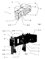
- the new drive 7 is, as shown in Figures 2 and 3, modular.
- a drive module 11 is provided with a traction sheave 12 for the support means 2 of the car 3 and counterweight 4, with a motor 21 required for driving the traction sheave 12 and in the example shown with a braking device 14 required for braking the traction sheave 12.
- the drive device 13 and the traction sheave 12 are assembled to form a drive module 11, as shown by way of example in FIG. 4.
- the drive module 11 with interfaces 15 provided. These interfaces 15 allow the connection of connecting parts 16. These connection parts 16 allow optionally an attachment of the drive module 11 within the shaft 5, for example, to the shaft ceiling 6 as shown in Figs. 1, 7 and 8 apparent or on the ground a conventional engine room 8 as shown in Fig. 5 or on the sockets 17 a previously disassembled previously old prime mover 9, as shown in Fig. 6.
- the interfaces 15 allow the connection in the other an extension 18, to which a deflection module 19 is connected is as shown in Figures 1, 2 and 3.
- the Extension 18 together with the drive module 11 and the Deflection module 19 allows adjustment of the support means distance according to the requirements of the elevator installation 1.
- the deflection module 19 in turn contains interfaces 15 which allows the connection of fasteners like those on the drive module 11 are used.
- the interface 15 of the drive module 11 and the interface 15 of the deflection made identical. This allows for easy installation, since when attaching the extension 18 no confusion consists.
- extension 18 and the deflection module 19 are designed such that the overall height of the drive 7 through the assembly of drive module 11, extension 18 and deflection module 19 is not changed.
- the interfaces 15 are designed functionally. she allow a modular composition of the drive 7 according to the requirements of the building.
- An additional advantage is that the individual modules and parts are transported separately to the installation site can. As a result, the transport units are small and wise a low individual weight. You can, for example with an old elevator system 9 in transported near the installation site in the building become.
- this drive 7 to replace existing drives 9 perfectly is suitable by being optimally adaptable to existing buildings is, i. he can both within the shaft 5 as arranged in an existing machine room 8.
- the support means distance is also easily adjustable. The Setting the suspension element distance affects the overall height of the drive 7 not.
- the drive module 11 optionally provided with a guide roller 20, which a, Independent of the support means distance, wrap the Traction sheave 12 ensured by the support means 2. is the support means 2 deflected using the guide roller 20 the wrap angle ( ⁇ ) is 90 ° to 180 °. These Looping can be achieved by the arrangement of the guide roller 20 to be changed. As a rule, a wrap angle ( ⁇ ) aimed at near 180 °.
- the drive module 11 can also be used directly without using the guide roller 20 become. Depending on the arrangement, this results in a wrap angle ( ⁇ ) of 90 ° or 180 °, as in the schematic diagrams Fig. 4a, 4b and 4c shown.
- the drive module 11 is preferably provided with a monitoring device provided (not shown), which the correct driving force transmission from the traction sheave 12 to Supporting means 2 and / or the correct tension of the suspension means 2 monitored.
- a monitoring device provided (not shown), which the correct driving force transmission from the traction sheave 12 to Supporting means 2 and / or the correct tension of the suspension means 2 monitored.
- the arrangement of the guide roller shown in Figure 4 20 allows control of the transmission of power, for example, the speed of the guide roller 20 is compared with the speed of the traction sheave 12. distinguish the two values are noticeably different from each other an incorrect transmission of the driving forces.
- the advantage of this design is the fact that the correct transmission of the driving force monitored directly on the drive 7 can be. This will increase security and availability the elevator system 1 increases because case-specifically the correct measures (maintenance request, shutdown, etc.) can be initialized quickly.
- the suspension element 2 has, as shown in FIGS. 4d to 4f a substantially round cross section or it has a substantially flat cross-section, wherein the surface serving to transmit the driving force smoothly, longitudinally structured, serrated, studded, perforated or of any desired length is another structure or, the support means 2 has a any cross section.
- the traction sheave is like that stated that the transmission of the driving force of the Traction sheave on the support means 2 functionally enabled is
- the drive 7 is not limited to a specific support means 2. It is suitable for a variety of carrying professional forms. It is advantageous if support means 2 are used, which are suitable for small deflection radii. As a result, the drive 7 can be made particularly small.
- the motor 21 of the drive module 11 arranged parallel axis to the traction sheave 12, wherein the motor 21 is connected by a drive belt 23 with a pulley 22 which is arranged coaxially with the traction sheave 12 ,
- This design requires little space in the width of the drive 7 and the transmission of the drive torque is low vibration.
- the motor 21 is arranged directly coaxial with the traction sheave 12.
- the advantage of this alternative is the fact that the overall length of the drive 7 is reduced
- the engine 21 is connected to the transmission shaft 24 by a transmission.
- the advantage of this alternative is the use of commercially available translation devices.
- the brake device 14 is advantageously arranged to act directly on the traction sheave shaft 24 or the traction sheave 12. This arrangement significantly reduces the risk of brake failure, as the braking force is introduced directly into the traction sheave 12.
- the advantage of this arrangement is that a safety-compliant braking system for stopping and holding a car 3 with intact support means 2 can be realized inexpensively.
- the brake device 14 is arranged to act directly on the shaft of the drive motor 21. This arrangement is inexpensive because a braking device 14 can be used with low braking torque. This arrangement usually requires further, known in the market, safety measures to catch a failure of the connection of drive motor 21 to traction sheave shaft 24.
- the brake device 14 or a further braking device may be arranged on the deflection module 19.
- the traction sheave 12 and / or a traction sheave shaft 24 and / or the pulley 22 is made in one piece. This embodiment enables a production-optimized and cost-effective design of the drive module 11.
- the drive module 11 is provided with interfaces 15, which allows the cultivation of several connecting parts 16.
- the advantage of this embodiment results from the universal applicability of the drive module 11.
- the interfaces 15 allow the attachment of the connection parts 16 required for a specific elevator installation 1.
- the interfaces 15 are, as shown in Figures 3, 4, 9 and 10, for example, slots or hole arrangements or jaws for receiving connection means.
- the connection parts 16 are optionally extension 18, deflection module 19, suspension or support modules 25, 26, or suspension means end connections 27 or further aids.
- the design of the drive module 11 with functional interfaces 15 allows the use of the drive module 11 for many types of elevators, and this allows a rational and cost-effective production of the product.
- a first advantageous connection part 16 is an extension 18, which is arranged with an end region on the interface 15 of the drive module 11, and at the other end region of a deflection module 19 is attached.
- the deflection module 19 has the drive module identical interface 15.
- the advantage of the extension 18 is that an adjustment of the support means distance is possible.
- universal drive and deflection modules can be used, which in turn allows a rational production of the drive.
- the deflection module 19 and the drive module 11 have the same interfaces 15. This is particularly advantageous because it increases the design options. For example, instead of the arrangement, drive module 11 and deflection module 19, two drive modules 11 can be used. As a result, the performance of the drive system 7 can be significantly increased.
- the interface 15 of the drive module 11 and the deflection module 19 for extension 18 allows a fine adjustability of the Tragstoffdistanz.
- This advantageous embodiment allows adjustment to the actually existing carrier distance. Thus, there is no skew, whereby a wear of the support means 2 is reduced.
- connection part 16 is a suspension module 25, which is arranged on the interface 15 of the drive module 11 and / or the deflection module 19, which allows the suspension of the drive to a shaft ceiling 6, or
- connection part 16 is a support module 26, which is arranged on the interface 15 of the drive module 11 and / or the deflection module 19, which allows the attachment of the drive 7 in a machine room 8 or on a shaft wall.
- the hanging or support modules 25,26 are advantageously provided with noise or vibration damping materials.
- the advantage of this embodiment is the fact that a building type appropriate attachment can be used.
- the suspension module 25 uses, for example, existing ⁇ ffnüngen in the shaft ceiling 6, or in the bottom of the overhead Engine room 8 to the drive 7 to the shaft ceiling 6 to hang, with the counterplates required in the machine room 8 are long and narrow, and between the existing machine sockets 17 are arranged.
- the counter plates Dependent on the execution of the engine room 8, the counter plates have other shapes, as for the arrangement reasonably yield. You can if necessary be executed for example round.
- the drive module 11 and / or the deflection module 19 is advantageously provided with Tragstoffenditatien 27.
- the advantage here is that the interfaces to the building be reduced because all the supporting forces from cabin 3 and Counterweight 4 are guided on the drive unit 7 and introduced via the suspension points of the drive 7 in the building become.
- the arrangement of the suspensions allows the use of a 2: 1 umhfitung arrangement in elevator systems 1, which in the old version were hung directly or 1: 1.
- This arrangement is characterized by a particularly advantageous design enables the Tragstoffendriven.
- the drive module 11 and / or the deflection module 19 is provided with an interface 15 for fastening an auxiliary hoist 28.
- the auxiliary hoist 28 is used for installation-related process of elevator material and / or installation personnel.
- This supplement allows a particularly efficient sequence of assembly of the drive 7 according to the invention, as shown by way of example in FIG. 13.
- the inventive drive 7 is transported by means of the old elevator installation 1 in the vicinity of the installation site and completed there with the necessary connection parts 16.
- the old cab 3 is now set and secured in the vicinity of the top stop and the old support members are dismantled.
- the inventive drive 7 is preferably lifted using the existing cable bushings and a mounted in the machine room 8 drawbar 29 to the shaft ceiling 6 and fixed by means of suspension module 25.
- auxiliary hoist 28 is now attached to, provided on the drive 7, interface 15.
- the cab 3 can now be moved and any components of the old engine room equipment, such as drive machine, control boxes, etc. can be transported by means of the auxiliary hoist 28. If the replacement of the remaining manhole equipment, depending on the conversion agreement replaced, the new support means 2 can be retracted, the auxiliary hoist 28 can be removed and the elevator system 1 is again available to the customer after a short conversion time.
- This described conversion process is just one possible example. It shows the advantageous use of the inventive drive 7.
- a supplementary embodiment prefers that the attachment TragstoffendENS 27 is provided with a monitoring for detecting the suspension medium tension.
- suitable measures can be initialized in the event of a deviation of the suspension element tension, such as, for example, a request by a service person or a shutdown of the elevator installation 1 before an unsafe operating state arises.
- the elevator 10 associated with the control and / or drive control is advantageously arranged in the engine room 8. Alternatively, it can also be arranged wholly or partly in the shaft 5 or in an easily accessible location, preferably in the vicinity of the drive.
- a machine room 8 is often available.
- the engine room 8 can not be used otherwise as a rule.
- a use of the machine room 8 for the arrangement of the new controller 10 and / or drive control offers.
- the electrical connection to the drive 7 is usually possible simply by existing openings in the shaft ceiling 6. It is particularly advantageous that an existing engine room 8 is used meaningful. Depending on the existing arrangement or possible use of the machine room 8, the best arrangement of the controller 10 and / or the drive control can be selected.
Priority Applications (7)
| Application Number | Priority Date | Filing Date | Title |
|---|---|---|---|
| EP04030856.1A EP1555236B1 (fr) | 2004-01-07 | 2004-12-28 | Entraînement d'ascenseur et procédés de conversion et d'installation d'un ;entraînement d'ascenseur |
| PL04030856T PL1555236T3 (pl) | 2004-01-07 | 2004-12-28 | Napęd dla instalacji dźwigowej i sposób przebudowy napędu w instalacji dźwigowej |
| EP05104962A EP1588978B1 (fr) | 2004-01-07 | 2004-12-28 | Entraînement d'ascenseur |
| EP14195765.4A EP2860144B1 (fr) | 2004-01-07 | 2004-12-28 | Entraînement pour un ascenseur |
| EP05006056.5A EP1553039B1 (fr) | 2004-01-07 | 2004-12-28 | Machinerie pour ascenseur |
| PL05006056T PL1553039T3 (pl) | 2004-01-07 | 2004-12-28 | Napęd instalacji dźwigowej |
| US11/421,107 US7624847B2 (en) | 2004-01-07 | 2006-05-31 | Drive for an elevator installation |
Applications Claiming Priority (3)
| Application Number | Priority Date | Filing Date | Title |
|---|---|---|---|
| EP04405010 | 2004-01-07 | ||
| EP04405010 | 2004-01-07 | ||
| EP04030856.1A EP1555236B1 (fr) | 2004-01-07 | 2004-12-28 | Entraînement d'ascenseur et procédés de conversion et d'installation d'un ;entraînement d'ascenseur |
Related Child Applications (6)
| Application Number | Title | Priority Date | Filing Date |
|---|---|---|---|
| EP14195765.4A Division-Into EP2860144B1 (fr) | 2004-01-07 | 2004-12-28 | Entraînement pour un ascenseur |
| EP14195765.4A Division EP2860144B1 (fr) | 2004-01-07 | 2004-12-28 | Entraînement pour un ascenseur |
| EP05104962A Division EP1588978B1 (fr) | 2004-01-07 | 2004-12-28 | Entraînement d'ascenseur |
| EP05104962A Division-Into EP1588978B1 (fr) | 2004-01-07 | 2004-12-28 | Entraînement d'ascenseur |
| EP05006056.5A Division-Into EP1553039B1 (fr) | 2004-01-07 | 2004-12-28 | Machinerie pour ascenseur |
| EP05006056.5A Division EP1553039B1 (fr) | 2004-01-07 | 2004-12-28 | Machinerie pour ascenseur |
Publications (2)
| Publication Number | Publication Date |
|---|---|
| EP1555236A1 true EP1555236A1 (fr) | 2005-07-20 |
| EP1555236B1 EP1555236B1 (fr) | 2018-09-26 |
Family
ID=34593654
Family Applications (4)
| Application Number | Title | Priority Date | Filing Date |
|---|---|---|---|
| EP04030856.1A Active EP1555236B1 (fr) | 2004-01-07 | 2004-12-28 | Entraînement d'ascenseur et procédés de conversion et d'installation d'un ;entraînement d'ascenseur |
| EP14195765.4A Active EP2860144B1 (fr) | 2004-01-07 | 2004-12-28 | Entraînement pour un ascenseur |
| EP05104962A Active EP1588978B1 (fr) | 2004-01-07 | 2004-12-28 | Entraînement d'ascenseur |
| EP05006056.5A Revoked EP1553039B1 (fr) | 2004-01-07 | 2004-12-28 | Machinerie pour ascenseur |
Family Applications After (3)
| Application Number | Title | Priority Date | Filing Date |
|---|---|---|---|
| EP14195765.4A Active EP2860144B1 (fr) | 2004-01-07 | 2004-12-28 | Entraînement pour un ascenseur |
| EP05104962A Active EP1588978B1 (fr) | 2004-01-07 | 2004-12-28 | Entraînement d'ascenseur |
| EP05006056.5A Revoked EP1553039B1 (fr) | 2004-01-07 | 2004-12-28 | Machinerie pour ascenseur |
Country Status (2)
| Country | Link |
|---|---|
| EP (4) | EP1555236B1 (fr) |
| PL (2) | PL1555236T3 (fr) |
Cited By (2)
| Publication number | Priority date | Publication date | Assignee | Title |
|---|---|---|---|---|
| EP1886957A1 (fr) | 2006-08-11 | 2008-02-13 | Inventio Ag | Courroie d'élévateur pour un élévateur et procédé de fabrication d'une telle courroie d'élévateur |
| DE202008001786U1 (de) | 2007-03-12 | 2008-12-24 | Inventio Ag | Aufzugsanlage, Tragmittel für eine Aufzugsanlage und Vorrichtung zur Herstellung eines Tragmittels |
Citations (8)
| Publication number | Priority date | Publication date | Assignee | Title |
|---|---|---|---|---|
| DE3912575A1 (de) * | 1988-04-18 | 1989-10-26 | Kone Elevator Gmbh | Verfahren zum pruefen und ueberwachen der reibung zwischen der treibscheibe und den tragseilen eines aufzugs |
| EP0763495A1 (fr) * | 1995-09-15 | 1997-03-19 | Inventio Ag | Chassis de machine |
| WO1999043597A2 (fr) * | 1998-02-26 | 1999-09-02 | Otis Elevator Company | Systeme d'ascenseur comprenant un local de machinerie compact |
| US6006865A (en) * | 1996-11-11 | 1999-12-28 | Inventio Ag | Lift installation with drive unit arranged in the lift shaft |
| JP2001171954A (ja) * | 1999-12-20 | 2001-06-26 | Mitsubishi Electric Corp | エレベータの巻上機支持装置 |
| WO2002008108A2 (fr) * | 2000-07-24 | 2002-01-31 | Otis Elevator Company | Systeme d'ascenseur utilisant un espace de construction minimum |
| WO2002079067A1 (fr) * | 2001-03-29 | 2002-10-10 | Mitsubishi Denki Kabushiki Kaisha | Methode de montage d'un treuil |
| US20030155188A1 (en) * | 2002-02-18 | 2003-08-21 | Andrzej Cholinski | Engine frame with counter-roller support for an elevator drive |
Family Cites Families (6)
| Publication number | Priority date | Publication date | Assignee | Title |
|---|---|---|---|---|
| JPH0761744A (ja) * | 1993-08-18 | 1995-03-07 | Otis Elevator Co | 巻き上げ式エレベーター |
| JPH09151059A (ja) * | 1995-12-01 | 1997-06-10 | Hitachi Ltd | エレベータ装置 |
| US6341669B1 (en) * | 2000-06-21 | 2002-01-29 | Otis Elevator Company | Pivoting termination for elevator rope |
| AU2001285634B2 (en) * | 2000-09-27 | 2006-09-14 | Inventio Ag | Elevator with drive unit mounted in a superior lateral section of the elevator hoistway |
| EP1448470B1 (fr) * | 2001-11-23 | 2007-01-24 | Inventio Ag | Ascenseur comprenant un moyen de transmission de type courroie, notamment une courroie dentee, en tant que moyen de support ou moyen d'entrainement |
| EP1333000A1 (fr) * | 2002-02-05 | 2003-08-06 | Monitor S.p.A. | Ascenseur à poulie de traction sans salle de machines |
-
2004
- 2004-12-28 PL PL04030856T patent/PL1555236T3/pl unknown
- 2004-12-28 EP EP04030856.1A patent/EP1555236B1/fr active Active
- 2004-12-28 EP EP14195765.4A patent/EP2860144B1/fr active Active
- 2004-12-28 PL PL05006056T patent/PL1553039T3/pl unknown
- 2004-12-28 EP EP05104962A patent/EP1588978B1/fr active Active
- 2004-12-28 EP EP05006056.5A patent/EP1553039B1/fr not_active Revoked
Patent Citations (8)
| Publication number | Priority date | Publication date | Assignee | Title |
|---|---|---|---|---|
| DE3912575A1 (de) * | 1988-04-18 | 1989-10-26 | Kone Elevator Gmbh | Verfahren zum pruefen und ueberwachen der reibung zwischen der treibscheibe und den tragseilen eines aufzugs |
| EP0763495A1 (fr) * | 1995-09-15 | 1997-03-19 | Inventio Ag | Chassis de machine |
| US6006865A (en) * | 1996-11-11 | 1999-12-28 | Inventio Ag | Lift installation with drive unit arranged in the lift shaft |
| WO1999043597A2 (fr) * | 1998-02-26 | 1999-09-02 | Otis Elevator Company | Systeme d'ascenseur comprenant un local de machinerie compact |
| JP2001171954A (ja) * | 1999-12-20 | 2001-06-26 | Mitsubishi Electric Corp | エレベータの巻上機支持装置 |
| WO2002008108A2 (fr) * | 2000-07-24 | 2002-01-31 | Otis Elevator Company | Systeme d'ascenseur utilisant un espace de construction minimum |
| WO2002079067A1 (fr) * | 2001-03-29 | 2002-10-10 | Mitsubishi Denki Kabushiki Kaisha | Methode de montage d'un treuil |
| US20030155188A1 (en) * | 2002-02-18 | 2003-08-21 | Andrzej Cholinski | Engine frame with counter-roller support for an elevator drive |
Non-Patent Citations (1)
| Title |
|---|
| PATENT ABSTRACTS OF JAPAN vol. 2000, no. 23 10 February 2001 (2001-02-10) * |
Cited By (2)
| Publication number | Priority date | Publication date | Assignee | Title |
|---|---|---|---|---|
| EP1886957A1 (fr) | 2006-08-11 | 2008-02-13 | Inventio Ag | Courroie d'élévateur pour un élévateur et procédé de fabrication d'une telle courroie d'élévateur |
| DE202008001786U1 (de) | 2007-03-12 | 2008-12-24 | Inventio Ag | Aufzugsanlage, Tragmittel für eine Aufzugsanlage und Vorrichtung zur Herstellung eines Tragmittels |
Also Published As
| Publication number | Publication date |
|---|---|
| PL1555236T3 (pl) | 2019-03-29 |
| EP1588978B1 (fr) | 2007-07-18 |
| EP1555236B1 (fr) | 2018-09-26 |
| EP1588978A2 (fr) | 2005-10-26 |
| EP1553039A3 (fr) | 2007-03-07 |
| PL1553039T3 (pl) | 2014-05-30 |
| EP1588978A3 (fr) | 2006-05-17 |
| EP1553039B1 (fr) | 2013-12-25 |
| EP2860144B1 (fr) | 2016-09-28 |
| EP1553039A2 (fr) | 2005-07-13 |
| EP2860144A1 (fr) | 2015-04-15 |
Similar Documents
| Publication | Publication Date | Title |
|---|---|---|
| EP1621509B1 (fr) | Positionnement de machine d'entraînement d'ascenseur | |
| DE60007512T2 (de) | Treibscheibenaufzug | |
| DE69517915T3 (de) | Antriebsscheibenaufzug | |
| DE69630081T2 (de) | Antriebsscheibenaufzug | |
| DE69919194T2 (de) | Treiberschaltung | |
| EP1700809B1 (fr) | Système d'ascenseur | |
| EP1772411A1 (fr) | Méthode pour installer un moyen de support d'une cabine d'ascenseur sur une cabine d'ascenseur et dans une gaine d'ascenseur | |
| EP0917518A1 (fr) | Ascenseur a poulies motrices | |
| EP2082983B1 (fr) | Installation d'ascenseur | |
| EP3478621B1 (fr) | Procédé pour l'implantation d'une installation d'ascenseur avec une hauteur de levage utile adaptable | |
| EP2346771B1 (fr) | Procédé de modernisation destiné à des installations d'ascenseur | |
| WO2019034381A1 (fr) | Système d'ascenseur | |
| EP2928805A1 (fr) | Ascenseur à deux niveaux avec distance entre cabines réglable | |
| WO2002068307A1 (fr) | Agencement d'elements d'equilibrage de poids | |
| EP3227216B1 (fr) | Ascenseur | |
| EP2860144B1 (fr) | Entraînement pour un ascenseur | |
| EP1555232B1 (fr) | Procédé de conversion et de installation d'un entraînement d'asceneur | |
| EP3114067B1 (fr) | Entraînement à courroie multiple pour une installation d'ascenseur | |
| EP1081086B1 (fr) | Installation d'ascenseur comprenant une unité d'entraínement disposée dans le puits d'ascenseur | |
| DE10319731A1 (de) | Aufzug | |
| EP3235770B1 (fr) | Procede de reequipement d'un ascenseur et ascenseur correspondant | |
| EP1045811B1 (fr) | Ascenseur a cables avec poulie motrice | |
| EP1673301B1 (fr) | Systeme d'entrainement concu pour des salles de machinerie etroites | |
| DE10348151A1 (de) | Antriebssystem für enge Triebwerksräume | |
| DE20320076U1 (de) | Antriebssystem für enge Triebwerksräume |
Legal Events
| Date | Code | Title | Description |
|---|---|---|---|
| PUAI | Public reference made under article 153(3) epc to a published international application that has entered the european phase |
Free format text: ORIGINAL CODE: 0009012 |
|
| AK | Designated contracting states |
Kind code of ref document: A1 Designated state(s): AT BE BG CH CY CZ DE DK EE ES FI FR GB GR HU IE IS IT LI LT LU MC NL PL PT RO SE SI SK TR |
|
| AX | Request for extension of the european patent |
Extension state: AL BA HR LV MK YU |
|
| 17P | Request for examination filed |
Effective date: 20060118 |
|
| AKX | Designation fees paid |
Designated state(s): AT BE BG CH CY CZ DE DK EE ES FI FR GB GR HU IE IS IT LI LT LU MC NL PL PT RO SE SI SK TR |
|
| 17Q | First examination report despatched |
Effective date: 20160707 |
|
| GRAP | Despatch of communication of intention to grant a patent |
Free format text: ORIGINAL CODE: EPIDOSNIGR1 |
|
| INTG | Intention to grant announced |
Effective date: 20180416 |
|
| GRAS | Grant fee paid |
Free format text: ORIGINAL CODE: EPIDOSNIGR3 |
|
| GRAA | (expected) grant |
Free format text: ORIGINAL CODE: 0009210 |
|
| AK | Designated contracting states |
Kind code of ref document: B1 Designated state(s): AT BE BG CH CY CZ DE DK EE ES FI FR GB GR HU IE IS IT LI LT LU MC NL PL PT RO SE SI SK TR |
|
| REG | Reference to a national code |
Ref country code: GB Ref legal event code: FG4D Free format text: NOT ENGLISH |
|
| REG | Reference to a national code |
Ref country code: CH Ref legal event code: EP |
|
| REG | Reference to a national code |
Ref country code: AT Ref legal event code: REF Ref document number: 1045758 Country of ref document: AT Kind code of ref document: T Effective date: 20181015 |
|
| REG | Reference to a national code |
Ref country code: IE Ref legal event code: FG4D Free format text: LANGUAGE OF EP DOCUMENT: GERMAN |
|
| REG | Reference to a national code |
Ref country code: DE Ref legal event code: R096 Ref document number: 502004015726 Country of ref document: DE |
|
| REG | Reference to a national code |
Ref country code: ES Ref legal event code: FG2A Ref document number: 2696948 Country of ref document: ES Kind code of ref document: T3 Effective date: 20190118 |
|
| REG | Reference to a national code |
Ref country code: NL Ref legal event code: MP Effective date: 20180926 |
|
| PG25 | Lapsed in a contracting state [announced via postgrant information from national office to epo] |
Ref country code: LT Free format text: LAPSE BECAUSE OF FAILURE TO SUBMIT A TRANSLATION OF THE DESCRIPTION OR TO PAY THE FEE WITHIN THE PRESCRIBED TIME-LIMIT Effective date: 20180926 Ref country code: BG Free format text: LAPSE BECAUSE OF FAILURE TO SUBMIT A TRANSLATION OF THE DESCRIPTION OR TO PAY THE FEE WITHIN THE PRESCRIBED TIME-LIMIT Effective date: 20181226 Ref country code: SE Free format text: LAPSE BECAUSE OF FAILURE TO SUBMIT A TRANSLATION OF THE DESCRIPTION OR TO PAY THE FEE WITHIN THE PRESCRIBED TIME-LIMIT Effective date: 20180926 Ref country code: GR Free format text: LAPSE BECAUSE OF FAILURE TO SUBMIT A TRANSLATION OF THE DESCRIPTION OR TO PAY THE FEE WITHIN THE PRESCRIBED TIME-LIMIT Effective date: 20181227 Ref country code: FI Free format text: LAPSE BECAUSE OF FAILURE TO SUBMIT A TRANSLATION OF THE DESCRIPTION OR TO PAY THE FEE WITHIN THE PRESCRIBED TIME-LIMIT Effective date: 20180926 |
|
| REG | Reference to a national code |
Ref country code: CH Ref legal event code: PK Free format text: BERICHTIGUNGEN |
|
| REG | Reference to a national code |
Ref country code: LT Ref legal event code: MG4D Effective date: 20180717 |
|
| RIC2 | Information provided on ipc code assigned after grant |
Ipc: B66B 11/08 20060101AFI20050413BHEP |
|
| PG25 | Lapsed in a contracting state [announced via postgrant information from national office to epo] |
Ref country code: EE Free format text: LAPSE BECAUSE OF FAILURE TO SUBMIT A TRANSLATION OF THE DESCRIPTION OR TO PAY THE FEE WITHIN THE PRESCRIBED TIME-LIMIT Effective date: 20180926 Ref country code: RO Free format text: LAPSE BECAUSE OF FAILURE TO SUBMIT A TRANSLATION OF THE DESCRIPTION OR TO PAY THE FEE WITHIN THE PRESCRIBED TIME-LIMIT Effective date: 20180926 Ref country code: NL Free format text: LAPSE BECAUSE OF FAILURE TO SUBMIT A TRANSLATION OF THE DESCRIPTION OR TO PAY THE FEE WITHIN THE PRESCRIBED TIME-LIMIT Effective date: 20180926 Ref country code: IS Free format text: LAPSE BECAUSE OF FAILURE TO SUBMIT A TRANSLATION OF THE DESCRIPTION OR TO PAY THE FEE WITHIN THE PRESCRIBED TIME-LIMIT Effective date: 20190126 Ref country code: CZ Free format text: LAPSE BECAUSE OF FAILURE TO SUBMIT A TRANSLATION OF THE DESCRIPTION OR TO PAY THE FEE WITHIN THE PRESCRIBED TIME-LIMIT Effective date: 20180926 |
|
| PG25 | Lapsed in a contracting state [announced via postgrant information from national office to epo] |
Ref country code: PT Free format text: LAPSE BECAUSE OF FAILURE TO SUBMIT A TRANSLATION OF THE DESCRIPTION OR TO PAY THE FEE WITHIN THE PRESCRIBED TIME-LIMIT Effective date: 20190126 Ref country code: SK Free format text: LAPSE BECAUSE OF FAILURE TO SUBMIT A TRANSLATION OF THE DESCRIPTION OR TO PAY THE FEE WITHIN THE PRESCRIBED TIME-LIMIT Effective date: 20180926 |
|
| REG | Reference to a national code |
Ref country code: DE Ref legal event code: R097 Ref document number: 502004015726 Country of ref document: DE |
|
| PG25 | Lapsed in a contracting state [announced via postgrant information from national office to epo] |
Ref country code: DK Free format text: LAPSE BECAUSE OF FAILURE TO SUBMIT A TRANSLATION OF THE DESCRIPTION OR TO PAY THE FEE WITHIN THE PRESCRIBED TIME-LIMIT Effective date: 20180926 Ref country code: MC Free format text: LAPSE BECAUSE OF FAILURE TO SUBMIT A TRANSLATION OF THE DESCRIPTION OR TO PAY THE FEE WITHIN THE PRESCRIBED TIME-LIMIT Effective date: 20180926 |
|
| PLBE | No opposition filed within time limit |
Free format text: ORIGINAL CODE: 0009261 |
|
| STAA | Information on the status of an ep patent application or granted ep patent |
Free format text: STATUS: NO OPPOSITION FILED WITHIN TIME LIMIT |
|
| PG25 | Lapsed in a contracting state [announced via postgrant information from national office to epo] |
Ref country code: LU Free format text: LAPSE BECAUSE OF NON-PAYMENT OF DUE FEES Effective date: 20181228 |
|
| 26N | No opposition filed |
Effective date: 20190627 |
|
| REG | Reference to a national code |
Ref country code: IE Ref legal event code: MM4A |
|
| PG25 | Lapsed in a contracting state [announced via postgrant information from national office to epo] |
Ref country code: IE Free format text: LAPSE BECAUSE OF NON-PAYMENT OF DUE FEES Effective date: 20181228 Ref country code: SI Free format text: LAPSE BECAUSE OF FAILURE TO SUBMIT A TRANSLATION OF THE DESCRIPTION OR TO PAY THE FEE WITHIN THE PRESCRIBED TIME-LIMIT Effective date: 20180926 |
|
| REG | Reference to a national code |
Ref country code: AT Ref legal event code: MM01 Ref document number: 1045758 Country of ref document: AT Kind code of ref document: T Effective date: 20181228 |
|
| PGFP | Annual fee paid to national office [announced via postgrant information from national office to epo] |
Ref country code: BE Payment date: 20191219 Year of fee payment: 16 |
|
| PG25 | Lapsed in a contracting state [announced via postgrant information from national office to epo] |
Ref country code: AT Free format text: LAPSE BECAUSE OF NON-PAYMENT OF DUE FEES Effective date: 20181228 |
|
| PG25 | Lapsed in a contracting state [announced via postgrant information from national office to epo] |
Ref country code: CY Free format text: LAPSE BECAUSE OF FAILURE TO SUBMIT A TRANSLATION OF THE DESCRIPTION OR TO PAY THE FEE WITHIN THE PRESCRIBED TIME-LIMIT Effective date: 20180926 Ref country code: HU Free format text: LAPSE BECAUSE OF FAILURE TO SUBMIT A TRANSLATION OF THE DESCRIPTION OR TO PAY THE FEE WITHIN THE PRESCRIBED TIME-LIMIT; INVALID AB INITIO Effective date: 20041228 |
|
| REG | Reference to a national code |
Ref country code: BE Ref legal event code: MM Effective date: 20201231 |
|
| PGFP | Annual fee paid to national office [announced via postgrant information from national office to epo] |
Ref country code: PL Payment date: 20211215 Year of fee payment: 18 |
|
| PGFP | Annual fee paid to national office [announced via postgrant information from national office to epo] |
Ref country code: TR Payment date: 20211215 Year of fee payment: 18 Ref country code: ES Payment date: 20220110 Year of fee payment: 18 |
|
| PG25 | Lapsed in a contracting state [announced via postgrant information from national office to epo] |
Ref country code: BE Free format text: LAPSE BECAUSE OF NON-PAYMENT OF DUE FEES Effective date: 20201231 |
|
| REG | Reference to a national code |
Ref country code: DE Ref legal event code: R084 Ref document number: 502004015726 Country of ref document: DE |
|
| PGFP | Annual fee paid to national office [announced via postgrant information from national office to epo] |
Ref country code: CH Payment date: 20221228 Year of fee payment: 19 |
|
| PGFP | Annual fee paid to national office [announced via postgrant information from national office to epo] |
Ref country code: DE Payment date: 20221227 Year of fee payment: 19 |
|
| PGFP | Annual fee paid to national office [announced via postgrant information from national office to epo] |
Ref country code: GB Payment date: 20231219 Year of fee payment: 20 |
|
| PGFP | Annual fee paid to national office [announced via postgrant information from national office to epo] |
Ref country code: IT Payment date: 20231221 Year of fee payment: 20 Ref country code: FR Payment date: 20231226 Year of fee payment: 20 |
|
| REG | Reference to a national code |
Ref country code: ES Ref legal event code: FD2A Effective date: 20240202 |
|
| PG25 | Lapsed in a contracting state [announced via postgrant information from national office to epo] |
Ref country code: ES Free format text: LAPSE BECAUSE OF NON-PAYMENT OF DUE FEES Effective date: 20221229 |
|
| PG25 | Lapsed in a contracting state [announced via postgrant information from national office to epo] |
Ref country code: ES Free format text: LAPSE BECAUSE OF NON-PAYMENT OF DUE FEES Effective date: 20221229 |
|
| PGFP | Annual fee paid to national office [announced via postgrant information from national office to epo] |
Ref country code: DE Payment date: 20231227 Year of fee payment: 20 Ref country code: CH Payment date: 20240102 Year of fee payment: 20 |