EP1553000B1 - Schienengeführtes Fahrzeugsystem - Google Patents
Schienengeführtes Fahrzeugsystem Download PDFInfo
- Publication number
- EP1553000B1 EP1553000B1 EP04028847.4A EP04028847A EP1553000B1 EP 1553000 B1 EP1553000 B1 EP 1553000B1 EP 04028847 A EP04028847 A EP 04028847A EP 1553000 B1 EP1553000 B1 EP 1553000B1
- Authority
- EP
- European Patent Office
- Prior art keywords
- area
- running
- rail guided
- vehicle
- vehicles
- Prior art date
- Legal status (The legal status is an assumption and is not a legal conclusion. Google has not performed a legal analysis and makes no representation as to the accuracy of the status listed.)
- Expired - Lifetime
Links
Images

Classifications
-
- G—PHYSICS
- G05—CONTROLLING; REGULATING
- G05D—SYSTEMS FOR CONTROLLING OR REGULATING NON-ELECTRIC VARIABLES
- G05D1/00—Control of position, course, altitude or attitude of land, water, air or space vehicles, e.g. using automatic pilots
- G05D1/60—Intended control result
- G05D1/646—Following a predefined trajectory, e.g. a line marked on the floor or a flight path
-
- B—PERFORMING OPERATIONS; TRANSPORTING
- B61—RAILWAYS
- B61L—GUIDING RAILWAY TRAFFIC; ENSURING THE SAFETY OF RAILWAY TRAFFIC
- B61L23/00—Control, warning or like safety means along the route or between vehicles or trains
- B61L23/002—Control or safety means for heart-points and crossings of aerial railways, funicular rack-railway
- B61L23/005—Automatic control or safety means for points for operator-less railway, e.g. transportation systems
-
- B—PERFORMING OPERATIONS; TRANSPORTING
- B61—RAILWAYS
- B61L—GUIDING RAILWAY TRAFFIC; ENSURING THE SAFETY OF RAILWAY TRAFFIC
- B61L27/00—Central railway traffic control systems; Trackside control; Communication systems specially adapted therefor
- B61L27/04—Automatic systems, e.g. controlled by train; Change-over to manual control
-
- B—PERFORMING OPERATIONS; TRANSPORTING
- B61—RAILWAYS
- B61L—GUIDING RAILWAY TRAFFIC; ENSURING THE SAFETY OF RAILWAY TRAFFIC
- B61L27/00—Central railway traffic control systems; Trackside control; Communication systems specially adapted therefor
- B61L27/20—Trackside control of safe travel of vehicle or train, e.g. braking curve calculation
-
- G—PHYSICS
- G05—CONTROLLING; REGULATING
- G05D—SYSTEMS FOR CONTROLLING OR REGULATING NON-ELECTRIC VARIABLES
- G05D1/00—Control of position, course, altitude or attitude of land, water, air or space vehicles, e.g. using automatic pilots
- G05D1/60—Intended control result
- G05D1/69—Coordinated control of the position or course of two or more vehicles
- G05D1/695—Coordinated control of the position or course of two or more vehicles for maintaining a fixed relative position of the vehicles, e.g. for convoy travelling or formation flight
Definitions
- the present invention relates to a rail guided vehicle system for overhead running vehicles.
- the Unexamined Japanese Patent Application Publication (Tokkai-Hei) No. 10-268937 discloses a rail guided vehicle system having stations each provided with a bar code so that every time a rail guided vehicle passes by the station, its position is reported to a system controller.
- the inventors have further improved this patent by examining prevention of jamming, avoidance of deadlocks, and the like. The inventors have thus completed the present invention.
- WO 03/035427 A which already discloses a rail guided vehicle system in which a plurality of rail guided vehicles are each provided with
- a plurality of rail guided vehicles are each provided with means for recognizing a current position and means for communication with a system controller, and the system controller transmits a running instruction to each of the plurality of rail guided vehicles in accordance with the current positions and state of other rail guided vehicles.
- the plurality of rail guided vehicles are each provided with means for intercepting communication between each of the other rail guided vehicles and the system controller so as to control running of the rail guided vehicle on the basis of the positions of other rail guided vehicles obtained by the interception. At least the positions of other rail guided vehicles have only to be used from the signals intercepted. However, preferably, the running of the rail guided vehicle is controlled utilizing the positions and state of other rail guided vehicles.
- the running is controlled by determining an inter-vehicle distance from the positions of other rail guided vehicles obtained by the interception.
- the system controller can recognize both the current positions and state of the rail guided vehicles.
- the system controller can thus efficiently operate the rail guided vehicle system. It is possible to, for example, avoid deadlocks, prevent jamming, and preferentially deploys empty rail guided vehicles in an area in which many loading requests have been made.
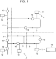
- FIGS 1 to 6 show an embodiment of the present invention by taking an overhead running vehicle system 2 by way of example.
- a running area for overhead running vehicles is divided into, for example, areas 3 to 7.
- a running rail and an electricity feeding rail are laid parallel to each other, for example, in a vertical direction.
- a power source (not shown in the drawings) supplies electricity to an electricity feeding line provided in the electricity feeding rail.
- the electricity feeding line is connected to an area controller 12 so that overhead running vehicles 10 can communicate with the area controller 12 via the electricity feeding line.
- Each of the overhead running vehicles 10 has a pickup coil or the like in proximity to the electricity feeding line to transmit and receive signals to and from the electricity feeding line in a non-contact manner and at a predetermined frequency. For example, a current for the non-contact electricity feeding via the electricity feeding line is 10 KHz.
- a frequency for the communication with the area controller 12 is 200 KHz.
- the electricity feeding line for the non-contact electricity feeding has a limited length and is thus laid out like a loop.
- the area controller 12 is provided for each area covered by one non-contact electricity feeding line. Further, a deadlock or the like is likely to occur in a branching or joining portion. Accordingly, one branching or joining portion is controlled by one area controller and is not distributed between two area controllers.
- a large number of overhead running vehicles 10 are arranged along the overhead running vehicle system 2.
- 100 or more overhead running vehicles are arranged.
- the overhead running vehicle 10 runs along the running rail.
- the overhead running vehicle 10 is fed with electricity and make communications, via the electricity feeding line.
- the overhead running vehicle 10 communicates with the area controller 12 of that area to follow instructions from this area controller 12.
- the overhead running vehicle 10 can wirelessly communicate with a system controller 14 directly or via the area controller 12.
- the wireless communication has only a small communication capacity and is thus used for predetermined communications such as transmission of a conveyance instruction from the system controller 14.
- the other communications are made via the communication line also used as the electricity feeding line.
- An exclusive communication line may be provided in the running rail for communications.
- the area controller 12 transmits the position and state of each overhead running vehicle 10 received from it, to the system controller 14 via a LAN (not shown in the drawings).
- the area controller 12 transmits an instruction received from the system controller 14, to the overhead running vehicle 10 by wired communication or the like.
- the state of the overhead running vehicle 10 includes, for example, running, remaining stopped and standing by, remaining stopped owing to a blocked route, loading, unloading, low-speed running owing to a defect in a running motor, running in the opposite direction (for a special reason), and remaining stopped owing to a defect (movement disabled until restoration).
- the area controller 12 also transmits information on the next destination (for example, a target station to which the overhead running vehicle 10 is to run or the next point through which the overhead running vehicle 10 is to pass).
- FIG. 2 shows the configuration of the overhead running vehicle 10.
- a map 20 describes the layout of a running route, that is, the running rail, and the arrangement of stations along the running rail. The distance between stations can also be read from the map 20. Further, the positions and state of the other overhead running vehicles are written on the map 20 so as to avoid collisions and deadlocks.
- the overhead running vehicles 10 report, to the system controller 14, their current positions and running destinations as well as their state such as conveying, unloading, or trouble (defect), each overhead running vehicle 10 can intercept these communications. The overhead running vehicle 10 then stores the current positions, state, and future running direction of the other overhead running vehicles 10 on the map 20.
- the overhead running vehicle 10 knows its own absolute position. The overhead running vehicle 10 can thus determine the distance between itself and each of the other overhead running vehicles 10 on the basis of the map 20. The overhead running vehicle 10 can also determine the state of the preceding overhead running vehicle 10(remaining stopped or running). Accordingly, the overhead running vehicle 10 can avoid collisions in spite of a short inter-vehicle distance or high-speed running. Since the overhead running vehicle 10 can determine the positions and state of other overhead running vehicles 10, it can avoid deadlocks and the like at its own discretion or on the basis of an instruction from the system controller 14.
- the overhead running vehicle 10 determines the current position and next running destination of another overhead running vehicle 10 from the map 20, it can determine whether or not the second overhead running vehicle 10 may interfere with its running. The overhead running vehicle 10 can then determine whether or not a deadlock may occur.
- An absolute position sensor 21 detects the absolute position (determined by an external sensor) of the overhead running vehicle 10 along the running route.
- the absolute position sensor 21 is, for example, a laser position sensor having a reflector provided at a predetermined position to detect the absolute position of the overhead running vehicle 10.
- marks may be provided at predetermined positions along the running route so as to be detected by the absolute position sensor 21. In this case, every time the overhead running vehicle 10 passes by any of the marks, its absolute position can be determined.
- An encoder 22 detects the rotation speed of a servo motor, running wheels, or the like of the overhead running vehicle 10. Thus, if the absolute position sensor 21 intermittently detects the absolute position, the position and speed of the overhead running vehicle 10 can be detected between detections of the absolute position.
- the overhead running vehicle 10 comprises a non-contact electricity feeding section 24 and a wired communication section 25 along the electricity feeding rail.
- the non-contact electricity feeding is carried out at a frequency of about 10 KHz.
- the wired communication is made at a frequency of about 200 KHz. Accordingly, these operations can be simultaneously performed using the same line.
- a radio communication section 26 communicates with the system controller 14, the area controllers 12, and the like by feeder communication. The radio communication section 26 is not essential.
- the overhead running vehicle 10 is provided with a general-purpose memory 28 and a CPU 30 to make various determinations and perform various types of control.
- a running driving section 32 drives running of the overhead running vehicle 10.
- a lateral drive 33 moves an elevation driving section 34 in a lateral direction of the running rail.
- the elevation driving section 34 and a rotative movement driving section 35 rotatively moves and elevates and lowers a chuck section 36 to transfer articles between the overhead running vehicle 10 and the appropriate station.
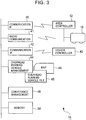
- FIG. 3 shows the configuration of the system controller 14.
- a communication interface 40 communicates with the area controller 12 via a LAN such as Ethernet.
- the communication interface 40 receives the current positions and state of the overhead running vehicles 10 via the area controller 12.
- the communication interface 40 further gives a running and conveyance instructions to the overhead running vehicles 10.
- a radio communication section 41 communicates directly with the overhead running vehicles 10 without using the area controller 12. However, the radio communication section 41 often has a small communication capacity. Accordingly, the radio communication section 41 may fail to communicate appropriately in certain areas depending on, for example, the layout of a semiconductor processing facility.
- a communication interface 42 communicates with, for example, a higher controller 43 that controls both conveyance and production via a separate LAN. The communication interface 42 receives a conveyance request and reports the results of conveyance.
- An overhead running vehicle managing section 44 manages the state and current positions of the overhead running vehicles 10.
- the overhead running vehicle managing section 44 stores the current positions and state of the overhead running vehicles 10 in, for example, an overhead running vehicle file 45.
- the positions and state of the overhead running vehicles 10 are also described in a map 46 so that the current positions and state can be managed using either the map 46 or the vehicle numbers of the overhead running vehicles 10. It is only necessary to provide one of the overhead running vehicle file 45 and map 46.
- the difference between the overhead running vehicle file 45 and the map 46 is that the overhead running vehicle file 45 allows retrievals based on the vehicle numbers or state of the overhead running vehicles 10, whereas the map 46 allows retrievals based on a position on the running route.
- a conveyance managing section 48 stores a file of conveyance requests received from the higher controller 43.
- the conveyance managing section 48 also stores a file of the results of conveyances such as executed conveyance requests, conveyance requests already assigned but being executed, and unassigned conveyance requests.
- 50 is a general-purpose memory.
- the overhead running vehicle 10 can determine the positions and state of other overhead running vehicles 10 by intercepting the communications between these overhead running vehicles 10 and the system controller 14. However, the overhead running vehicle 10 cannot determine the positions or state of the overhead running vehicles 10 in the other areas. Thus, the system controller 14 gives the overhead running vehicle 10 various instructions besides the conveyance instruction. However, within one area, each overhead running vehicle 10 can, for example, avoid deadlocks or collisions at its own discretion without relying on instructions from the system controller 14.
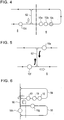
- Figure 4 shows how to prevent jamming.
- the leading overhead running vehicle 10c in the area 6 is assumed to be unmovable owing to any trouble, with the succeeding overhead running vehicle 10b, 10a thus stopped.
- the system controller 14 knows not only that overhead running vehicles 10a ⁇ 10c are in the area 6 but also that the overhead running vehicle 10c is in trouble.
- the system controller 14 can instruct a succeeding overhead running vehicle controller 10d to run around the area 6 via a bypass 52. This serves to prevent the spread of jamming.
- the system controller 14 also knows that the overhead running vehicles 10a, 10b are operating normally as well as their current positions (particularly the positional order of the overhead running vehicles 10a, 10b).
- the overhead running vehicles 10a, 10b can be backed in this order to escape from the bypass 52. If jamming is occurring in the area in which the overhead running vehicle 10 is running, it may change its running path without waiting for an instruction from the system controller 14, if possible, in order to avoid the jamming. However, in this case, the overhead running vehicle 10 having changed its running path reports the change to the system controller 14 via the area controller 12 or the like.
- Figure 5 schematically shows how to avoid a deadlock.
- the overhead running vehicle 10e and the overhead running vehicle 10f are attempting to run along the bypass 52 in the opposite directions.
- the overhead running vehicle 10e can determine that a deadlock is likely to occur because the overhead running vehicle 10f is attempting to enter the bypass 52.
- the system controller 14 is notified that the overhead running vehicle 10e attempting to run along the bypass 52 stopped to change its state to "remaining stopped”. Then, the system controller 14 can instruct the overhead running vehicle 10f to enter the bypass 52.
- the overhead running vehicle 10f may intercept the communication between the overhead running vehicle 10e and the system controller 14 to enter the bypass 52, without waiting for an instruction from the system controller 14. This enables a possible deadlock to be easily avoided.
- FIG 6 shows an example in which many loading requests have been made in an area 54, so that the overhead running vehicles 10 need to be deployed in the area 54 as much as possible.
- the system controller 14 receives information on the area in which loading requests have been made, from the higher controller 43 as a conveyance request. Upon determining that empty overhead running vehicles 10g, 10h are in nearby areas 55, 56, the system controller instructs these overhead running vehicles 10g, 10h to move to the area 54. This enables to the overhead running vehicles 10 to be deployed in accordance with the loading requests.
- the embodiment shows the overhead running vehicles 10 but the present invention is applicable to rail guided vehicles running on the ground. Further, a loading device may or may not be mounted on the vehicle.
- the embodiment can produce the following effects.
Landscapes
- Engineering & Computer Science (AREA)
- Mechanical Engineering (AREA)
- Transportation (AREA)
- Health & Medical Sciences (AREA)
- Heart & Thoracic Surgery (AREA)
- Aviation & Aerospace Engineering (AREA)
- Radar, Positioning & Navigation (AREA)
- Remote Sensing (AREA)
- Physics & Mathematics (AREA)
- General Physics & Mathematics (AREA)
- Automation & Control Theory (AREA)
- Control Of Position, Course, Altitude, Or Attitude Of Moving Bodies (AREA)
- Control And Safety Of Cranes (AREA)
- Platform Screen Doors And Railroad Systems (AREA)
Claims (1)
- Schienengeführtes Fahrzeugsystem (2) mit einer Mehrzahl schienengeführter Fahrzeuge (10) und einem Laufbereich für diese Fahrzeuge (10), einschließlich Verzweigungs- und Verbindungsabschnitte in einer Hauptlauflinie,
wobei jedes der schienengeführten Fahrzeuge (10) versehen ist mit:- Mitteln zum Erkennen einer aktuellen Position,- Mitteln zur Kommunikation mit einem Systemsteuerer/-regler (14), wobei der Systemsteuerer/-regler (14) zu jedem der Mehrzahl schienengeführter Fahrzeuge (10) eine Laufanweisung gemäß den aktuellen Positionen und dem Status anderer schienengeführter Fahrzeuge (10) überträgt,- Mittel zum Abfangen der Kommunikation zwischen jedem der anderen Fahrzeuge (10) und dem Systemsteuerer/-regler (14), und- Mittel zur Kontrolle des eigenen Laufs, basierend auf den durch das Abfangen erhaltenen Positionen der anderen schienengeführten Fahrzeuge (10),dadurch gekennzeichnet, dass- der Laufbereich in eine Mehrzahl von Bereichen (3-7) unterteilt ist,- das System eine Mehrzahl von Bereichsreglern (12) umfasst, welche jeweils mit einem Bereich (3-7) verbunden sind und mit den schienengeführten Fahrzeugen (10) in dem jeweiligen Bereich (3-7) und mit dem Systemsteuerer/-regler (14) kommunizieren können,- in der Hauptlauflinie ein Verzweigungsabschnitt und ein Verbindungsabschnitt, falls vorhanden, in einem Bereich (3-4) vorliegen und von dem Bereichsregler (12) dieses Bereichs gesteuert/geregelt werden,
und- ein Nebenweg (52) mit Verzweigungsabschnitten und Verbindungsabschnitten an den jeweiligen Enden des Nebenwegs (52), falls vorhanden, in demselben Bereich (5) vorgesehen ist,wobei
jedes der schienengeführten Fahrzeuge (10) in demselben Bereich (3-7) die Kommunikation zwischen dem Systemsteuerer/-regler (14) und jedem der anderen schienengeführten Fahrzeuge (10) in demselben Bereich abfängt, um den eigenen Lauf in diesem Bereich basierend auf den Positionen der anderen schienengeführten Fahrzeuge (10) in demselben Bereich zu steuern/regeln, um Stau und Zusammenstöße zu vermeiden, und wobei jedes Fahrzeug (10) mit einem Bereichsregler (12) kommuniziert und wobei jedes Fahrzeug (10) auch mit dem Systemsteuerer/-regler (14) kommuniziert.
Applications Claiming Priority (2)
| Application Number | Priority Date | Filing Date | Title |
|---|---|---|---|
| JP2004004302A JP3874192B2 (ja) | 2004-01-09 | 2004-01-09 | 有軌道台車システム |
| JP2004004302 | 2004-01-09 |
Publications (2)
| Publication Number | Publication Date |
|---|---|
| EP1553000A1 EP1553000A1 (de) | 2005-07-13 |
| EP1553000B1 true EP1553000B1 (de) | 2017-04-26 |
Family
ID=34587726
Family Applications (1)
| Application Number | Title | Priority Date | Filing Date |
|---|---|---|---|
| EP04028847.4A Expired - Lifetime EP1553000B1 (de) | 2004-01-09 | 2004-12-06 | Schienengeführtes Fahrzeugsystem |
Country Status (5)
| Country | Link |
|---|---|
| US (1) | US7303169B2 (de) |
| EP (1) | EP1553000B1 (de) |
| JP (1) | JP3874192B2 (de) |
| KR (1) | KR100810528B1 (de) |
| TW (1) | TW200523190A (de) |
Families Citing this family (23)
| Publication number | Priority date | Publication date | Assignee | Title |
|---|---|---|---|---|
| JP4221603B2 (ja) * | 2005-03-31 | 2009-02-12 | 村田機械株式会社 | 天井走行車システム |
| JP4281067B2 (ja) * | 2005-04-11 | 2009-06-17 | 村田機械株式会社 | 搬送車システム |
| JP4438095B2 (ja) * | 2005-05-26 | 2010-03-24 | 村田機械株式会社 | 搬送システム |
| ITMI20051393A1 (it) * | 2005-07-20 | 2007-01-21 | Marsilli & Co | Linea di produzione automatica per la lavorazione e l'assiemaggio di componenti per industrie in genere |
| JP4172477B2 (ja) * | 2005-08-17 | 2008-10-29 | 村田機械株式会社 | パターンの実機への実装方法 |
| KR100944154B1 (ko) | 2005-09-13 | 2010-02-24 | 무라타 기카이 가부시키가이샤 | 유궤도 대차 시스템 |
| JP5002347B2 (ja) * | 2007-06-22 | 2012-08-15 | 中西金属工業株式会社 | 有軌道搬送システム |
| TW201013820A (en) * | 2008-09-24 | 2010-04-01 | Inotera Memories Inc | Automatic transport system and control method thereof |
| WO2010035411A1 (ja) * | 2008-09-26 | 2010-04-01 | 村田機械株式会社 | 搬送車システム |
| JP5146855B2 (ja) * | 2010-08-09 | 2013-02-20 | 村田機械株式会社 | 天井走行車システム |
| US8996161B2 (en) | 2011-05-19 | 2015-03-31 | Rockwell Automation, Inc. | Controlled architecture for transport systems |
| CN102372014B (zh) * | 2011-10-28 | 2014-05-07 | 中冶南方工程技术有限公司 | 冶金工厂铁水运输物流仿真系统中的机车自动避碰方法 |
| JP5527619B2 (ja) * | 2011-11-24 | 2014-06-18 | 株式会社ダイフク | 天井設置型の物品搬送設備 |
| BR112013028739A2 (pt) * | 2012-07-03 | 2017-01-24 | Modutram Mexico S A De C V | sistema e método de controle para frota de veículos automatizados |
| KR101440569B1 (ko) * | 2013-06-04 | 2014-09-17 | (주)엔스퀘어 | 무인반송차량 관리 시스템 |
| IL230866A0 (en) * | 2014-02-06 | 2014-09-30 | Dan Yehuda Schlesinger | Device for surface transportation |
| US10181873B2 (en) * | 2015-12-28 | 2019-01-15 | Stmicroelectronics, Inc. | Enhanced powerline communication methods and devices |
| JP6698399B2 (ja) * | 2016-03-29 | 2020-05-27 | 北陽電機株式会社 | 搬送制御装置及び搬送台車の合流点通過方法 |
| TWI694022B (zh) * | 2018-03-01 | 2020-05-21 | 正修學校財團法人正修科技大學 | 軌道立體檢測系統 |
| CA3039328A1 (en) | 2018-04-06 | 2019-10-06 | Sst Systems, Inc. | Conveyor system with automated carriers |
| CN114755992A (zh) * | 2022-05-25 | 2022-07-15 | 长鑫存储技术有限公司 | 搬送系统及其异常控制方法 |
| GB2642932A (en) * | 2023-02-28 | 2026-01-28 | Magway Ltd | Control system and method for a rail-track system |
| KR102682823B1 (ko) * | 2023-08-03 | 2024-07-08 | (주)캔탑스 | 전력선 통신을 이용한 대차 위치기반 합류 통과 제어 시스템 |
Family Cites Families (7)
| Publication number | Priority date | Publication date | Assignee | Title |
|---|---|---|---|---|
| US4766547A (en) * | 1986-04-14 | 1988-08-23 | Transfer Technologies, Inc. | Computer controlled conveyor system |
| JPS6373304A (ja) * | 1986-09-16 | 1988-04-02 | Shinko Electric Co Ltd | 無人搬送車の衝突防止装置 |
| JPH05324064A (ja) * | 1992-05-26 | 1993-12-07 | Toshiba Corp | 軌道台車制御装置 |
| TW386875B (en) * | 1995-01-11 | 2000-04-11 | Shinko Electric Co Ltd | Transportation system |
| JPH10268937A (ja) | 1997-03-24 | 1998-10-09 | Murata Mach Ltd | 有軌道台車の運行制御システム |
| DE19822803A1 (de) * | 1998-05-20 | 1999-11-25 | Alcatel Sa | Verfahren zum Betrieb von Schienenfahrzeugen sowie Zugsteuerzentrale und Fahrzeuggerät hierfür |
| WO2003035427A2 (en) | 2001-10-22 | 2003-05-01 | Cascade Engineering, Inc. | Individual transport control and communication system |
-
2004
- 2004-01-09 JP JP2004004302A patent/JP3874192B2/ja not_active Expired - Fee Related
- 2004-08-17 TW TW093124691A patent/TW200523190A/zh not_active IP Right Cessation
- 2004-10-27 KR KR1020040086192A patent/KR100810528B1/ko not_active Expired - Fee Related
- 2004-12-06 EP EP04028847.4A patent/EP1553000B1/de not_active Expired - Lifetime
- 2004-12-10 US US11/008,183 patent/US7303169B2/en not_active Expired - Fee Related
Non-Patent Citations (1)
| Title |
|---|
| None * |
Also Published As
| Publication number | Publication date |
|---|---|
| JP2005196655A (ja) | 2005-07-21 |
| KR100810528B1 (ko) | 2008-03-10 |
| TWI324130B (de) | 2010-05-01 |
| KR20050073515A (ko) | 2005-07-14 |
| EP1553000A1 (de) | 2005-07-13 |
| US20050150416A1 (en) | 2005-07-14 |
| JP3874192B2 (ja) | 2007-01-31 |
| TW200523190A (en) | 2005-07-16 |
| US7303169B2 (en) | 2007-12-04 |
Similar Documents
| Publication | Publication Date | Title |
|---|---|---|
| EP1553000B1 (de) | Schienengeführtes Fahrzeugsystem | |
| KR101425451B1 (ko) | 주행차의 주행 제어 시스템과 제어 방법 | |
| CN107291076B (zh) | 物品输送设备 | |
| US7853371B2 (en) | Article transport apparatus and article transport method | |
| US10310513B2 (en) | Conveyance control device and merging point passing method for carrying cart | |
| JP6963908B2 (ja) | 物品搬送車 | |
| US6109568A (en) | Control system and method for moving multiple automated vehicles along a monorail | |
| US10684613B2 (en) | Data communication method for reducing working time of automated material handling system | |
| CN104111654A (zh) | 行驶车辆控制系统以及行驶车辆控制方法 | |
| CN102161457A (zh) | 行驶车系统和行驶车系统中的通信方法 | |
| EP3988474A1 (de) | Förderfahrzeug | |
| KR20170133970A (ko) | 교차로에서의 무인 반송차의 트래픽 흐름 제어 방법, 시스템 및 이를 위한 트래픽 제어기 | |
| US20060069470A1 (en) | Bi-directional absolute automated tracking system for material handling | |
| JP2009237866A (ja) | 搬送システム及び搬送車 | |
| JP2020052911A (ja) | 運行制御システム | |
| JP4471118B2 (ja) | 物品搬送設備 | |
| JP2011166671A (ja) | 走行台車システム | |
| JP2008171088A (ja) | 走行車システム | |
| JP2019120992A (ja) | Agv制御システム | |
| US11217092B2 (en) | Transport vehicle system | |
| JP7172371B2 (ja) | 無人搬送装置の運行制御システム | |
| WO2024219025A1 (ja) | 搬送システム | |
| JP2011164059A (ja) | 走行台車システム |
Legal Events
| Date | Code | Title | Description |
|---|---|---|---|
| PUAI | Public reference made under article 153(3) epc to a published international application that has entered the european phase |
Free format text: ORIGINAL CODE: 0009012 |
|
| AK | Designated contracting states |
Kind code of ref document: A1 Designated state(s): AT BE BG CH CY CZ DE DK EE ES FI FR GB GR HU IE IS IT LI LT LU MC NL PL PT RO SE SI SK TR |
|
| AX | Request for extension of the european patent |
Extension state: AL BA HR LV MK YU |
|
| 17P | Request for examination filed |
Effective date: 20050905 |
|
| AKX | Designation fees paid |
Designated state(s): DE FR GB IT |
|
| 17Q | First examination report despatched |
Effective date: 20090306 |
|
| RIC1 | Information provided on ipc code assigned before grant |
Ipc: B61L 27/00 20060101ALI20161221BHEP Ipc: B61L 27/04 20060101AFI20161221BHEP Ipc: B61L 23/00 20060101ALI20161221BHEP |
|
| GRAP | Despatch of communication of intention to grant a patent |
Free format text: ORIGINAL CODE: EPIDOSNIGR1 |
|
| INTG | Intention to grant announced |
Effective date: 20170214 |
|
| RIN1 | Information on inventor provided before grant (corrected) |
Inventor name: KUZUYA, MOTOHIKO Inventor name: MORIGUCHI, TOSHIKI Inventor name: NISHIMURA, KEN Inventor name: HORI, KIKUO |
|
| GRAS | Grant fee paid |
Free format text: ORIGINAL CODE: EPIDOSNIGR3 |
|
| GRAA | (expected) grant |
Free format text: ORIGINAL CODE: 0009210 |
|
| AK | Designated contracting states |
Kind code of ref document: B1 Designated state(s): DE FR GB IT |
|
| REG | Reference to a national code |
Ref country code: GB Ref legal event code: FG4D |
|
| REG | Reference to a national code |
Ref country code: DE Ref legal event code: R096 Ref document number: 602004051145 Country of ref document: DE |
|
| REG | Reference to a national code |
Ref country code: DE Ref legal event code: R097 Ref document number: 602004051145 Country of ref document: DE |
|
| PG25 | Lapsed in a contracting state [announced via postgrant information from national office to epo] |
Ref country code: IT Free format text: LAPSE BECAUSE OF FAILURE TO SUBMIT A TRANSLATION OF THE DESCRIPTION OR TO PAY THE FEE WITHIN THE PRESCRIBED TIME-LIMIT Effective date: 20170426 |
|
| PLBE | No opposition filed within time limit |
Free format text: ORIGINAL CODE: 0009261 |
|
| STAA | Information on the status of an ep patent application or granted ep patent |
Free format text: STATUS: NO OPPOSITION FILED WITHIN TIME LIMIT |
|
| 26N | No opposition filed |
Effective date: 20180129 |
|
| GBPC | Gb: european patent ceased through non-payment of renewal fee |
Effective date: 20171206 |
|
| REG | Reference to a national code |
Ref country code: FR Ref legal event code: ST Effective date: 20180831 |
|
| PG25 | Lapsed in a contracting state [announced via postgrant information from national office to epo] |
Ref country code: FR Free format text: LAPSE BECAUSE OF NON-PAYMENT OF DUE FEES Effective date: 20180102 |
|
| PG25 | Lapsed in a contracting state [announced via postgrant information from national office to epo] |
Ref country code: GB Free format text: LAPSE BECAUSE OF NON-PAYMENT OF DUE FEES Effective date: 20171206 |
|
| PGFP | Annual fee paid to national office [announced via postgrant information from national office to epo] |
Ref country code: DE Payment date: 20191210 Year of fee payment: 16 |
|
| REG | Reference to a national code |
Ref country code: DE Ref legal event code: R119 Ref document number: 602004051145 Country of ref document: DE |
|
| PG25 | Lapsed in a contracting state [announced via postgrant information from national office to epo] |
Ref country code: DE Free format text: LAPSE BECAUSE OF NON-PAYMENT OF DUE FEES Effective date: 20210701 |