EP1550564B1 - Pneu radial pour motocyclette - Google Patents
Pneu radial pour motocyclette Download PDFInfo
- Publication number
- EP1550564B1 EP1550564B1 EP03728128A EP03728128A EP1550564B1 EP 1550564 B1 EP1550564 B1 EP 1550564B1 EP 03728128 A EP03728128 A EP 03728128A EP 03728128 A EP03728128 A EP 03728128A EP 1550564 B1 EP1550564 B1 EP 1550564B1
- Authority
- EP
- European Patent Office
- Prior art keywords
- rigidity
- tire
- carcass
- belt
- less
- Prior art date
- Legal status (The legal status is an assumption and is not a legal conclusion. Google has not performed a legal analysis and makes no representation as to the accuracy of the status listed.)
- Expired - Lifetime
Links
- 238000005452 bending Methods 0.000 claims description 38
- 230000002093 peripheral effect Effects 0.000 claims description 17
- 239000011324 bead Substances 0.000 claims description 6
- 239000000835 fiber Substances 0.000 claims description 4
- 230000000052 comparative effect Effects 0.000 description 6
- 238000000034 method Methods 0.000 description 4
- 238000005259 measurement Methods 0.000 description 3
- 238000012360 testing method Methods 0.000 description 3
- 239000004677 Nylon Substances 0.000 description 2
- 238000010276 construction Methods 0.000 description 2
- 238000006073 displacement reaction Methods 0.000 description 2
- 229920001778 nylon Polymers 0.000 description 2
- 238000006243 chemical reaction Methods 0.000 description 1
- 238000013461 design Methods 0.000 description 1
- 238000011161 development Methods 0.000 description 1
- 230000000694 effects Effects 0.000 description 1
- 238000011156 evaluation Methods 0.000 description 1
- 238000005457 optimization Methods 0.000 description 1
- 230000003014 reinforcing effect Effects 0.000 description 1
- 238000009877 rendering Methods 0.000 description 1
- 238000012549 training Methods 0.000 description 1
Images


Classifications
-
- B—PERFORMING OPERATIONS; TRANSPORTING
- B60—VEHICLES IN GENERAL
- B60C—VEHICLE TYRES; TYRE INFLATION; TYRE CHANGING; CONNECTING VALVES TO INFLATABLE ELASTIC BODIES IN GENERAL; DEVICES OR ARRANGEMENTS RELATED TO TYRES
- B60C9/00—Reinforcements or ply arrangement of pneumatic tyres
- B60C9/18—Structure or arrangement of belts or breakers, crown-reinforcing or cushioning layers
-
- B—PERFORMING OPERATIONS; TRANSPORTING
- B60—VEHICLES IN GENERAL
- B60C—VEHICLE TYRES; TYRE INFLATION; TYRE CHANGING; CONNECTING VALVES TO INFLATABLE ELASTIC BODIES IN GENERAL; DEVICES OR ARRANGEMENTS RELATED TO TYRES
- B60C9/00—Reinforcements or ply arrangement of pneumatic tyres
- B60C9/02—Carcasses
- B60C9/04—Carcasses the reinforcing cords of each carcass ply arranged in a substantially parallel relationship
-
- B—PERFORMING OPERATIONS; TRANSPORTING
- B60—VEHICLES IN GENERAL
- B60C—VEHICLE TYRES; TYRE INFLATION; TYRE CHANGING; CONNECTING VALVES TO INFLATABLE ELASTIC BODIES IN GENERAL; DEVICES OR ARRANGEMENTS RELATED TO TYRES
- B60C9/00—Reinforcements or ply arrangement of pneumatic tyres
- B60C9/02—Carcasses
- B60C9/04—Carcasses the reinforcing cords of each carcass ply arranged in a substantially parallel relationship
- B60C9/08—Carcasses the reinforcing cords of each carcass ply arranged in a substantially parallel relationship the cords extend transversely from bead to bead, i.e. radial ply
-
- B—PERFORMING OPERATIONS; TRANSPORTING
- B60—VEHICLES IN GENERAL
- B60C—VEHICLE TYRES; TYRE INFLATION; TYRE CHANGING; CONNECTING VALVES TO INFLATABLE ELASTIC BODIES IN GENERAL; DEVICES OR ARRANGEMENTS RELATED TO TYRES
- B60C2200/00—Tyres specially adapted for particular applications
- B60C2200/10—Tyres specially adapted for particular applications for motorcycles, scooters or the like
-
- Y—GENERAL TAGGING OF NEW TECHNOLOGICAL DEVELOPMENTS; GENERAL TAGGING OF CROSS-SECTIONAL TECHNOLOGIES SPANNING OVER SEVERAL SECTIONS OF THE IPC; TECHNICAL SUBJECTS COVERED BY FORMER USPC CROSS-REFERENCE ART COLLECTIONS [XRACs] AND DIGESTS
- Y10—TECHNICAL SUBJECTS COVERED BY FORMER USPC
- Y10T—TECHNICAL SUBJECTS COVERED BY FORMER US CLASSIFICATION
- Y10T152/00—Resilient tires and wheels
- Y10T152/10—Tires, resilient
- Y10T152/10495—Pneumatic tire or inner tube
- Y10T152/10765—Characterized by belt or breaker structure
-
- Y—GENERAL TAGGING OF NEW TECHNOLOGICAL DEVELOPMENTS; GENERAL TAGGING OF CROSS-SECTIONAL TECHNOLOGIES SPANNING OVER SEVERAL SECTIONS OF THE IPC; TECHNICAL SUBJECTS COVERED BY FORMER USPC CROSS-REFERENCE ART COLLECTIONS [XRACs] AND DIGESTS
- Y10—TECHNICAL SUBJECTS COVERED BY FORMER USPC
- Y10T—TECHNICAL SUBJECTS COVERED BY FORMER US CLASSIFICATION
- Y10T152/00—Resilient tires and wheels
- Y10T152/10—Tires, resilient
- Y10T152/10495—Pneumatic tire or inner tube
- Y10T152/10855—Characterized by the carcass, carcass material, or physical arrangement of the carcass materials
Definitions
- This invention relates to a pneumatic radial tire suitable for a motorcycle conducting a high-speed cornering while contacting a side edge portion of a tire tread with ground, particularly a front wheel thereof, and more particularly it proposes a technique that a steering stability in the high-speed cornering is largely improved while sufficiently developing various performances such as a high-speed durability, a straight-running stability and the like.
- the pneumatic radial tire for the motorcycle exclusively used in the running on urban areas is possible to sufficiently develop the desired performances by giving a large camber angle without deeply pursuing optimization on various bending rigidities of a belt, a rigidity balance and the like, which highly exerts on the steering stability in the high-speed cornering while contacting the tread contacting face with ground up to a side edge position.
- the invention is to solve the above problems inherent to the conventional pneumatic motorcycle tire and to provide a pneumatic radial tire for a motorcycle capable of sufficiently developing various performances such as high-speed durability, straight-running stability and the like but also developing an excellent steering stability in the aforementioned large camber running.
- the out-of-plane bending rigidity in the widthwise direction (Sb) is 3.92-6.86 N/mm and the in-plane bending rigidity in the peripheral direction (Sa) is 0.49-1.47 N/mm.
- Aspect ratio used herein is an "aspect ratio” defined in JATMA YEAR BOOK or a “NOMINAL ASPECT RATIO” defined in ETORTO STANDARD MANUAL.
- the in-plane bending rigidity in the peripheral direction of the tread portion (Sa) means a rigidity to a force acting to a peripheral component in the tread portion from a widthwise direction of the tread. Concretely, it can be determined by measuring and calculating (force/displacement) when a sample A of 15 mm in width formed by cutting a tread portion of a product tire in the peripheral direction of the tire as shown by a solid line in FIG. 1 is set to a measuring device as shown in FIG. 2 at a posture of directing cut faces up and down and a pushing force is applied to an up-side cut face.
- the out-of-plane bending rigidity in the widthwise direction of the tread portion (Sb) means a rigidity to an external force acting to a widthwise component of the tread portion in a pushing direction of the tread contacting face.
- This rigidity can be determined by measuring and calculating (force/displacement) when a sample B of 15 mm in width formed by cutting a tread portion of a product tire in the widthwise direction of the tread as shown by a phantom line in FIG. 1 is set to a measuring device as shown in FIG. 2 at a posture of rendering the tread contacting face into an up-side face and a pushing force is applied to the up-side face.
- the tensile strength at break (Edci) of the carcass ply cord is made to not less than 980 MPa and the tensile strength at break (Edbj) of the belt layer cord is made to not less than 2350 MPa, whereby a desired tire case strength can be ensured without increasing the number of carcass plies, end count of the carcass ply cords and the like, and a belt strength enough to provide an excellent hoop effect in the high-speed running can be ensured without increasing the number of the belt layers and the like. In this case, therefore, the increase of tire weight can be prevented.
- the absolute value of the carcass total rigidity (Fc) is made to not less than 30000 and the absolute value of the belt total rigidity is made to not less than 170000, whereby a desired durability can be given to the tire.
- the absolute value of the carcass total rigidity is less than 30000, it is difficult to ensure the straight-running stability and the steering stability in the high-speed cornering, while when the absolute value of the belt total rigidity is less than 170000, it is difficult to ensure the high-speed durability and the steering stability in the high-speed cornering.
- ) as a ratio of absolute value of carcass total rigidity (Fc) to absolute value of belt total rigidity (Fb) is within a range of 0.10-0.50.
- the ground contacting posture of the front wheeled tire is kaleidoscopically changed by the braking in the going into a corner, application of camber angle and handling in the cornering, straight-running after the passing through the corner and the like, or various inputs are repeatedly applied to the tire.
- the in-plane bending rigidity of the tread portion in the peripheral direction (Sa) is made to not less than 0.49 N/mm for particularly ensuring the steering stability in the high-speed cornering.
- the out-of-plane bending rigidity of the tread portion in the widthwise direction (Sb) is restricted to not more than 6.86 N/mm.
- the out-of-plane bending rigidity (Sb) is less than 3.92 N/mm, the rigidity comes short of.
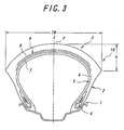
- numeral 1 is a pair of bead portions, numeral 2 a sidewall portion continuing to each of the bead portions 1 and extending outward therefrom in a radial direction, and numeral 3 a tread portion toroidally extending and continuing to each of the sidewall portions.
- the illustrated tire has an aspect ratio of 0.50-0.85.
- a radial carcass 5 reinforcing the above portions 1, 2, 3 is arranged so as to toroidally extend between bead cores 4 arranged in the respective bead portions 1.
- the carcass 5 is comprised of at least one carcass ply 6 containing organic fiber cords each extended at an angle of 60-90° with respect to an equatorial plane S of the tire.
- a belt 9 comprised of two or more belt layers 7, 8 in which belt layer cords are crossed with each other between these layers, preferably these cords extend in a direction opposite to each other with respect to the equatorial plane of the tire and an angle of the belt layer cord with respect to the equatorial plane S of the tire is within a range of 15-40°.
- the organic fiber cord constituting the carcass ply 6, i.e. the carcass ply cord has a tensile strength at break (Edci) of not less than 980 MPa, while an absolute value of a carcass total rigidity obtained by adding a carcass rigidity (Fci) defined as a product of the tensile strength at break (Edci) and an end count (Emci) of the carcass ply cords per a length of 50 cm in the equatorial plane of the tire with respect to the respective carcass plies 6 is set in not less than 30000.
- Edci tensile strength at break
- the cord of each belt layer has a tensile strength at break (Edbj) of not less than 2350 MPa, while an absolute value of a belt total rigidity (Fb) obtained by adding a belt rigidity (Fbj) defined as a product of the tensile strength at break (Edbj) and an end count (Nmbj) of the belt layer cords per a length of 50 cm in the equatorial plane of the tire with respect to the respective belt layers 7, 8 is set in not less than 170000.
- ) as a ratio of absolute value of carcass total rigidity to absolute value of belt total rigidity is set in a range of 0.10-0.50.
- the in-plane bending rigidity in the peripheral direction (Sa) is set in a range of 0.49-1.47 N/mm
- the out-of-plane bending rigidity in the widthwise direction (Sb) is set in a range of 3.92-6.86 N/mm
- the rigidity ratio (Sb/Sa) as a ratio of out-of-plane bending rigidity (Sb) to in-plane bending rigidity (Sa) is set in a range of 4.20-9.10.
- the development of high steering stability in the large camber running can be guaranteed by selecting the tensile strength at break of the respective cord, various rigidities and rigidity ratio within the above ranges without increasing the tire weight and with the sufficient securement of basic performances such as excellent high-speed durability, straight-running property and the like.
- a tread curvature under no load as a ratio of a distance h in radial direction from a tire outermost point P on the equatorial plane S to a position of a tread maximum width to a tread maximum width TW equal to a tire maximum width in the figure is set to not less than 0.23 but not more than 0.5.
- the cornering speed is 120 km/h, and as the index of the steering stability becomes larger, the result is better.
- a comparative tire of the following Table 1 is a control tire and the performance thereof is 100 as an index.
- a change of the steering stability when the in-plane bending rigidity in the radial direction (Sa) is variously changed in the tread portion of the front wheel tire is measured in the same manner as in Example 1 to obtain results as shown by a graph in FIG. 5 .
- the comparative tire of Table 1 is also control, and the performance thereof is 100 as an index.
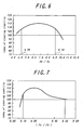
- a change of the steering stability by changing the bending rigidity ratio (Sb/Sa) in the tread portion of the front wheel tire is measured in the same manner as in Example 1 to obtain results as shown in FIG. 6 .
- control tire is also the comparative tire of Table 1, and the performance thereof is 100 as an index.
- ) as a ratio of absolute value of carcass total rigidity to absolute value of belt total rigidity (Fb) is measured in the same manner as in Example 1 to obtain results as shown in FIG. 7 .
- control tire is the comparative tire of Table 1.
- An actual running test is carried out by a motorcycle using a front wheel tire having a tire size of 120/70 ZR17 (rim width: 3.50 inch, internal pressure: 206 kPa) and a rear wheel tire having a tire size of 190/55 ZR17 (rim width: 6.00 inch, internal pressure: 186 kPa), in which the steering stability in the high-speed turning is evaluated by a driver's feeling to obtain results shown in Table 1.
- Table 1 are also shown constitutional forms of an example tire and a comparative tire used as a front wheel tire, respectively.
- the example tire can largely improve the steering stability in the high-speed cornering because various rigidity requirements and the like are satisfied.
- the high steering stability can be developed even when the tire is subjected to a large camber angle enough to contact the side edge portion of the tread contacting area with ground.
Landscapes
- Engineering & Computer Science (AREA)
- Mechanical Engineering (AREA)
- Tires In General (AREA)
Claims (3)
- Bandage pneumatique radial pour motocycle, comprenant une paire de parties de talon, une paire de parties de flanc, une partie de bande de roulement, s'étendant toroïdalement et se poursuivant jusqu'aux parties de flanc, une carcasse comprenant une ou plusieurs nappes de carcasse contenant des câblés de fibres organiques, s'étendant chacun à un angle compris entre 60 et 90° par rapport à un plan équatorial du bandage pneumatique, et une ceinture comprenant au moins deux nappes de ceinture contenant chacune des câblés s'étendant à un angle compris entre 15 et 40° par rapport au plan équatorial et agencés au niveau d'un côté périphérique externe d'une partie de sommet de la carcasse, de sorte que les câbles des nappes se croisent, et ayant un rapport d'aspect compris entre 0,50 et 0,85 ; dans lequel
une résistance à la rupture (Edci) du câblé de la nappe de carcasse n'est pas inférieure à 980 MPa, une valeur absolue d'une rigidité totale de la carcasse (Fc = ΣFci) déterminée en additionnant une rigidité de la carcasse (FCi), définie comme un produit de la résistance à la rupture (Edci), et une densité (Emci) des câblés de la nappe de carcasse pour une longueur de 50 cm dans le plan équatorial du bandage pneumatique par rapport aux nappes de carcasse respectives n'étant pas inférieure à 30000 ; et
une résistance à la rupture (Edbj) du câblé de la nappe de ceinture n'est pas inférieure à 2350 MPa, une valeur absolue d'une rigidité totale de la ceinture (Fb = ΣFbj) déterminée en additionnant une rigidité de la ceinture (Fbj), définie comme un produit de la résistance à la rupture (Edbj), et une densité (Nmbj) des câblés de la nappe de ceinture pour une longueur de 50 cm dans le plan équatorial du bandage pneumatique par rapport aux nappes de ceinture respectives n'étant pas inférieure à 170000 ; et
un rapport de la rigidité à la flexion (Sb/Sa) entre la rigidité à la flexion hors du plan dans une direction de la largeur (Sb) et la rigidité à la flexion dans le plan, dans une direction périphérique (Sa) dans la partie de la bande de roulement, est compris dans un intervalle allant de 4,20 à 9,10. - Bandage pneumatique radial pour motocycle selon la revendication 1, dans lequel la rigidité à la flexion hors du plan dans la direction de la largeur (Sb) est comprise entre 3,92 et 6,86 N/mm, la rigidité à la flexion dans le plan dans la direction périphérique (Sa) étant comprise entre 0,49 et 1,47 N/mm.
- Bandage pneumatique radial pour motocycle selon les revendications 1 ou 2, dans lequel un rapport de rigidité (FC/Fb), constituant un rapport entre la valeur absolue de la rigidité totale de la carcasse (Fc) et la valeur absolue de la rigidité totale de la ceinture (Fb) est compris dans un intervalle allant de 0,10 à 0,50.
Applications Claiming Priority (3)
| Application Number | Priority Date | Filing Date | Title |
|---|---|---|---|
| JP2002150997 | 2002-05-24 | ||
| JP2002150997 | 2002-05-24 | ||
| PCT/JP2003/006297 WO2003099590A1 (fr) | 2002-05-24 | 2003-05-20 | Peu radial pour motocycle |
Publications (3)
| Publication Number | Publication Date |
|---|---|
| EP1550564A1 EP1550564A1 (fr) | 2005-07-06 |
| EP1550564A4 EP1550564A4 (fr) | 2007-12-26 |
| EP1550564B1 true EP1550564B1 (fr) | 2009-04-22 |
Family
ID=29561239
Family Applications (1)
| Application Number | Title | Priority Date | Filing Date |
|---|---|---|---|
| EP03728128A Expired - Lifetime EP1550564B1 (fr) | 2002-05-24 | 2003-05-20 | Pneu radial pour motocyclette |
Country Status (7)
| Country | Link |
|---|---|
| US (1) | US7025101B2 (fr) |
| EP (1) | EP1550564B1 (fr) |
| JP (1) | JP4714464B2 (fr) |
| CN (1) | CN100357120C (fr) |
| DE (1) | DE60327340D1 (fr) |
| ES (1) | ES2323455T3 (fr) |
| WO (1) | WO2003099590A1 (fr) |
Families Citing this family (6)
| Publication number | Priority date | Publication date | Assignee | Title |
|---|---|---|---|---|
| EP1712375B1 (fr) * | 2004-01-26 | 2010-12-01 | Bridgestone Corporation | Pneumatique a structure radiale pour motocycle |
| JP2006103420A (ja) * | 2004-10-01 | 2006-04-20 | Sumitomo Rubber Ind Ltd | 自動二輪車用ラジアルタイヤ |
| JP4601476B2 (ja) * | 2005-03-30 | 2010-12-22 | 株式会社ブリヂストン | 自動二輪車用空気入りラジアルタイヤ |
| CN102300723B (zh) * | 2008-12-22 | 2014-08-13 | 倍耐力轮胎股份公司 | 用于两轮车辆的轮胎及用于制造该轮胎的工艺 |
| CN102390225B (zh) * | 2011-10-24 | 2013-06-12 | 厦门正新橡胶工业有限公司 | 低扁平摩托车轮胎 |
| JP7608861B2 (ja) * | 2021-02-18 | 2025-01-07 | 住友ゴム工業株式会社 | 二輪自動車用タイヤ対 |
Family Cites Families (12)
| Publication number | Priority date | Publication date | Assignee | Title |
|---|---|---|---|---|
| JPS60229806A (ja) * | 1984-04-27 | 1985-11-15 | Yokohama Rubber Co Ltd:The | 空気入りタイヤ |
| JPH0288307A (ja) * | 1988-09-26 | 1990-03-28 | Sumitomo Rubber Ind Ltd | 自動二輪車用ラジアルタイヤ |
| JPH0532103A (ja) | 1991-01-16 | 1993-02-09 | Sumitomo Rubber Ind Ltd | 自動二輪車用ラジアルタイヤ |
| DE69301366T2 (de) | 1992-04-06 | 1996-05-30 | Sumitomo Rubber Ind | Motorradreifen |
| JPH0640210A (ja) * | 1992-04-06 | 1994-02-15 | Sumitomo Rubber Ind Ltd | 自動二輪車用タイヤ |
| JPH0624207A (ja) | 1992-07-08 | 1994-02-01 | Sumitomo Rubber Ind Ltd | 自動二輪車用ラジアルタイヤ |
| GB9403230D0 (en) | 1994-02-19 | 1994-04-13 | Sumitomo Rubber Ind | Motorcycle radial tyre |
| US5529102A (en) | 1994-02-19 | 1996-06-25 | Sumitomo Rubber Industries, Ltd. | Motorcycle radial tire with supplementary breaker ply |
| JPH11502901A (ja) * | 1995-03-31 | 1999-03-09 | アクゾ ノーベル ナムローゼ フェンノートシャップ | 工業的用途のためのセルロースヤーン及びコード |
| GB9620978D0 (en) | 1996-10-08 | 1996-11-27 | Sumitomo Rubber Ind | Motorcycle radial tyre |
| CN1128069C (zh) * | 1997-08-14 | 2003-11-19 | 倍耐力轮胎有限公司 | 特别用于两轮机动车的高横向曲率轮胎对 |
| DE60031806T2 (de) * | 1999-07-07 | 2007-09-20 | Sumitomo Rubber Industries Ltd., Kobe | Luftreifen |
-
2003
- 2003-05-20 ES ES03728128T patent/ES2323455T3/es not_active Expired - Lifetime
- 2003-05-20 EP EP03728128A patent/EP1550564B1/fr not_active Expired - Lifetime
- 2003-05-20 CN CNB038147130A patent/CN100357120C/zh not_active Expired - Fee Related
- 2003-05-20 WO PCT/JP2003/006297 patent/WO2003099590A1/fr not_active Ceased
- 2003-05-20 JP JP2004507095A patent/JP4714464B2/ja not_active Expired - Fee Related
- 2003-05-20 DE DE60327340T patent/DE60327340D1/de not_active Expired - Lifetime
- 2003-05-20 US US10/515,022 patent/US7025101B2/en not_active Expired - Fee Related
Also Published As
| Publication number | Publication date |
|---|---|
| JP4714464B2 (ja) | 2011-06-29 |
| US7025101B2 (en) | 2006-04-11 |
| WO2003099590A1 (fr) | 2003-12-04 |
| CN100357120C (zh) | 2007-12-26 |
| JPWO2003099590A1 (ja) | 2005-09-22 |
| DE60327340D1 (de) | 2009-06-04 |
| US20050205188A1 (en) | 2005-09-22 |
| CN1662394A (zh) | 2005-08-31 |
| EP1550564A4 (fr) | 2007-12-26 |
| ES2323455T3 (es) | 2009-07-16 |
| EP1550564A1 (fr) | 2005-07-06 |
Similar Documents
| Publication | Publication Date | Title |
|---|---|---|
| EP2179867B1 (fr) | Pneu pour véhicule à moteur et à deux roues | |
| EP2206612B1 (fr) | Pneu pour motocyclette | |
| EP1923235B1 (fr) | Pneu hors route | |
| EP2159079B1 (fr) | Pneu pour véhicule à moteur à deux roues | |
| EP1859961B1 (fr) | Pneu pour motocyclette | |
| CA1213201A (fr) | Pneumatique pour vehicules | |
| US7025101B2 (en) | Pneumatic radial tire with specified tread portion bending rigidity ratio | |
| JP2002205513A (ja) | 空気入りラジアルタイヤ | |
| EP2196331B1 (fr) | Pneu pour véhicule à moteur à deux roues | |
| JP2009051350A (ja) | 自動二輪車用空気入りタイヤ | |
| EP0835768B1 (fr) | Bandages pneumatiques | |
| JP2003080906A (ja) | Atv用ラジアルタイヤ | |
| JP2009029211A (ja) | 自動二輪車用空気入りタイヤ | |
| EP3636457A1 (fr) | Ensemble de pneus pour véhicule à trois roues | |
| JP3821942B2 (ja) | 自動二輪車用空気入りタイヤ | |
| EP1712375B1 (fr) | Pneumatique a structure radiale pour motocycle | |
| JP4601476B2 (ja) | 自動二輪車用空気入りラジアルタイヤ | |
| EP1772294B1 (fr) | Pneumatique pour motocyclette | |
| US20050045261A1 (en) | Radial tire for motorcycle | |
| JP2009051428A (ja) | 自動二輪車用タイヤ対 | |
| KR100497979B1 (ko) | 승용차용 공기압 타이어 | |
| CN114953851B (zh) | 二轮机动车用轮胎对 | |
| JPH11245615A (ja) | 二輪自動車用空気入りバイアスタイヤ | |
| EP3332992A1 (fr) | Pneu pour motocyclettes |
Legal Events
| Date | Code | Title | Description |
|---|---|---|---|
| PUAI | Public reference made under article 153(3) epc to a published international application that has entered the european phase |
Free format text: ORIGINAL CODE: 0009012 |
|
| 17P | Request for examination filed |
Effective date: 20041124 |
|
| AK | Designated contracting states |
Kind code of ref document: A1 Designated state(s): AT BE BG CH CY CZ DE DK EE ES FI FR GB GR HU IE IT LI LU MC NL PT RO SE SI SK TR |
|
| RBV | Designated contracting states (corrected) |
Designated state(s): DE ES FR GB IT |
|
| A4 | Supplementary search report drawn up and despatched |
Effective date: 20071122 |
|
| GRAP | Despatch of communication of intention to grant a patent |
Free format text: ORIGINAL CODE: EPIDOSNIGR1 |
|
| GRAS | Grant fee paid |
Free format text: ORIGINAL CODE: EPIDOSNIGR3 |
|
| GRAA | (expected) grant |
Free format text: ORIGINAL CODE: 0009210 |
|
| AK | Designated contracting states |
Kind code of ref document: B1 Designated state(s): DE ES FR GB IT |
|
| REG | Reference to a national code |
Ref country code: GB Ref legal event code: FG4D |
|
| REF | Corresponds to: |
Ref document number: 60327340 Country of ref document: DE Date of ref document: 20090604 Kind code of ref document: P |
|
| REG | Reference to a national code |
Ref country code: ES Ref legal event code: FG2A Ref document number: 2323455 Country of ref document: ES Kind code of ref document: T3 |
|
| PLBE | No opposition filed within time limit |
Free format text: ORIGINAL CODE: 0009261 |
|
| STAA | Information on the status of an ep patent application or granted ep patent |
Free format text: STATUS: NO OPPOSITION FILED WITHIN TIME LIMIT |
|
| 26N | No opposition filed |
Effective date: 20100125 |
|
| PGFP | Annual fee paid to national office [announced via postgrant information from national office to epo] |
Ref country code: DE Payment date: 20120516 Year of fee payment: 10 |
|
| PG25 | Lapsed in a contracting state [announced via postgrant information from national office to epo] |
Ref country code: DE Free format text: LAPSE BECAUSE OF NON-PAYMENT OF DUE FEES Effective date: 20131203 |
|
| REG | Reference to a national code |
Ref country code: DE Ref legal event code: R119 Ref document number: 60327340 Country of ref document: DE Effective date: 20131203 |
|
| REG | Reference to a national code |
Ref country code: FR Ref legal event code: CA Effective date: 20140812 |
|
| REG | Reference to a national code |
Ref country code: FR Ref legal event code: PLFP Year of fee payment: 14 |
|
| PGFP | Annual fee paid to national office [announced via postgrant information from national office to epo] |
Ref country code: GB Payment date: 20160520 Year of fee payment: 14 Ref country code: ES Payment date: 20160512 Year of fee payment: 14 |
|
| PGFP | Annual fee paid to national office [announced via postgrant information from national office to epo] |
Ref country code: FR Payment date: 20160520 Year of fee payment: 14 Ref country code: IT Payment date: 20160524 Year of fee payment: 14 |
|
| GBPC | Gb: european patent ceased through non-payment of renewal fee |
Effective date: 20170520 |
|
| REG | Reference to a national code |
Ref country code: FR Ref legal event code: ST Effective date: 20180131 |
|
| PG25 | Lapsed in a contracting state [announced via postgrant information from national office to epo] |
Ref country code: GB Free format text: LAPSE BECAUSE OF NON-PAYMENT OF DUE FEES Effective date: 20170520 |
|
| PG25 | Lapsed in a contracting state [announced via postgrant information from national office to epo] |
Ref country code: FR Free format text: LAPSE BECAUSE OF NON-PAYMENT OF DUE FEES Effective date: 20170531 Ref country code: IT Free format text: LAPSE BECAUSE OF NON-PAYMENT OF DUE FEES Effective date: 20170520 |
|
| REG | Reference to a national code |
Ref country code: ES Ref legal event code: FD2A Effective date: 20180705 |
|
| PG25 | Lapsed in a contracting state [announced via postgrant information from national office to epo] |
Ref country code: ES Free format text: LAPSE BECAUSE OF NON-PAYMENT OF DUE FEES Effective date: 20170521 |