EP1550511A2 - Vorrichtung und Verfahren zur Aerosolerzeugung - Google Patents
Vorrichtung und Verfahren zur Aerosolerzeugung Download PDFInfo
- Publication number
- EP1550511A2 EP1550511A2 EP05007516A EP05007516A EP1550511A2 EP 1550511 A2 EP1550511 A2 EP 1550511A2 EP 05007516 A EP05007516 A EP 05007516A EP 05007516 A EP05007516 A EP 05007516A EP 1550511 A2 EP1550511 A2 EP 1550511A2
- Authority
- EP
- European Patent Office
- Prior art keywords
- aerosol
- generating
- carrier gas
- pressure
- diaphragm
- Prior art date
- Legal status (The legal status is an assumption and is not a legal conclusion. Google has not performed a legal analysis and makes no representation as to the accuracy of the status listed.)
- Granted
Links
- 239000000443 aerosol Substances 0.000 title claims abstract description 140
- 238000004519 manufacturing process Methods 0.000 title claims description 26
- 239000012159 carrier gas Substances 0.000 claims abstract description 47
- 239000007788 liquid Substances 0.000 claims abstract description 43
- 238000000034 method Methods 0.000 claims description 10
- 238000005461 lubrication Methods 0.000 claims description 6
- 238000001816 cooling Methods 0.000 claims description 5
- 230000000712 assembly Effects 0.000 claims description 3
- 238000000429 assembly Methods 0.000 claims description 3
- 150000002148 esters Chemical class 0.000 claims description 2
- 238000011144 upstream manufacturing Methods 0.000 claims 1
- 239000003921 oil Substances 0.000 description 26
- 230000007423 decrease Effects 0.000 description 5
- 239000002245 particle Substances 0.000 description 4
- 238000011105 stabilization Methods 0.000 description 4
- 230000015572 biosynthetic process Effects 0.000 description 2
- 239000002826 coolant Substances 0.000 description 2
- 238000005516 engineering process Methods 0.000 description 2
- 239000007789 gas Substances 0.000 description 2
- 230000006641 stabilisation Effects 0.000 description 2
- 239000004820 Pressure-sensitive adhesive Substances 0.000 description 1
- 238000000889 atomisation Methods 0.000 description 1
- 230000033228 biological regulation Effects 0.000 description 1
- 238000011109 contamination Methods 0.000 description 1
- 239000005068 cooling lubricant Substances 0.000 description 1
- 238000011161 development Methods 0.000 description 1
- 230000018109 developmental process Effects 0.000 description 1
- 238000010586 diagram Methods 0.000 description 1
- 238000005553 drilling Methods 0.000 description 1
- 239000000295 fuel oil Substances 0.000 description 1
- 239000003292 glue Substances 0.000 description 1
- 230000036571 hydration Effects 0.000 description 1
- 238000006703 hydration reaction Methods 0.000 description 1
- 230000007774 longterm Effects 0.000 description 1
- 239000000314 lubricant Substances 0.000 description 1
- 230000001050 lubricating effect Effects 0.000 description 1
- 238000012544 monitoring process Methods 0.000 description 1
- 239000003973 paint Substances 0.000 description 1
- 238000005070 sampling Methods 0.000 description 1
- 239000007921 spray Substances 0.000 description 1
- 238000005507 spraying Methods 0.000 description 1
- 230000000087 stabilizing effect Effects 0.000 description 1
- 238000003860 storage Methods 0.000 description 1
- 230000009885 systemic effect Effects 0.000 description 1
Images


Classifications
-
- B—PERFORMING OPERATIONS; TRANSPORTING
- B05—SPRAYING OR ATOMISING IN GENERAL; APPLYING FLUENT MATERIALS TO SURFACES, IN GENERAL
- B05B—SPRAYING APPARATUS; ATOMISING APPARATUS; NOZZLES
- B05B7/00—Spraying apparatus for discharge of liquids or other fluent materials from two or more sources, e.g. of liquid and air, of powder and gas
- B05B7/02—Spray pistols; Apparatus for discharge
- B05B7/04—Spray pistols; Apparatus for discharge with arrangements for mixing liquids or other fluent materials before discharge
-
- B—PERFORMING OPERATIONS; TRANSPORTING
- B05—SPRAYING OR ATOMISING IN GENERAL; APPLYING FLUENT MATERIALS TO SURFACES, IN GENERAL
- B05B—SPRAYING APPARATUS; ATOMISING APPARATUS; NOZZLES
- B05B7/00—Spraying apparatus for discharge of liquids or other fluent materials from two or more sources, e.g. of liquid and air, of powder and gas
- B05B7/0012—Apparatus for achieving spraying before discharge from the apparatus
-
- B—PERFORMING OPERATIONS; TRANSPORTING
- B01—PHYSICAL OR CHEMICAL PROCESSES OR APPARATUS IN GENERAL
- B01F—MIXING, e.g. DISSOLVING, EMULSIFYING OR DISPERSING
- B01F23/00—Mixing according to the phases to be mixed, e.g. dispersing or emulsifying
- B01F23/20—Mixing gases with liquids
- B01F23/21—Mixing gases with liquids by introducing liquids into gaseous media
- B01F23/213—Mixing gases with liquids by introducing liquids into gaseous media by spraying or atomising of the liquids
- B01F23/2132—Mixing gases with liquids by introducing liquids into gaseous media by spraying or atomising of the liquids using nozzles
-
- B—PERFORMING OPERATIONS; TRANSPORTING
- B01—PHYSICAL OR CHEMICAL PROCESSES OR APPARATUS IN GENERAL
- B01F—MIXING, e.g. DISSOLVING, EMULSIFYING OR DISPERSING
- B01F35/00—Accessories for mixers; Auxiliary operations or auxiliary devices; Parts or details of general application
- B01F35/20—Measuring; Control or regulation
- B01F35/21—Measuring
- B01F35/211—Measuring of the operational parameters
- B01F35/2113—Pressure
-
- B—PERFORMING OPERATIONS; TRANSPORTING
- B01—PHYSICAL OR CHEMICAL PROCESSES OR APPARATUS IN GENERAL
- B01F—MIXING, e.g. DISSOLVING, EMULSIFYING OR DISPERSING
- B01F35/00—Accessories for mixers; Auxiliary operations or auxiliary devices; Parts or details of general application
- B01F35/20—Measuring; Control or regulation
- B01F35/22—Control or regulation
- B01F35/221—Control or regulation of operational parameters, e.g. level of material in the mixer, temperature or pressure
- B01F35/2211—Amount of delivered fluid during a period
-
- B—PERFORMING OPERATIONS; TRANSPORTING
- B01—PHYSICAL OR CHEMICAL PROCESSES OR APPARATUS IN GENERAL
- B01F—MIXING, e.g. DISSOLVING, EMULSIFYING OR DISPERSING
- B01F35/00—Accessories for mixers; Auxiliary operations or auxiliary devices; Parts or details of general application
- B01F35/71—Feed mechanisms
- B01F35/712—Feed mechanisms for feeding fluids
-
- B—PERFORMING OPERATIONS; TRANSPORTING
- B01—PHYSICAL OR CHEMICAL PROCESSES OR APPARATUS IN GENERAL
- B01F—MIXING, e.g. DISSOLVING, EMULSIFYING OR DISPERSING
- B01F35/00—Accessories for mixers; Auxiliary operations or auxiliary devices; Parts or details of general application
- B01F35/71—Feed mechanisms
- B01F35/717—Feed mechanisms characterised by the means for feeding the components to the mixer
- B01F35/7179—Feed mechanisms characterised by the means for feeding the components to the mixer using sprayers, nozzles or jets
-
- B—PERFORMING OPERATIONS; TRANSPORTING
- B01—PHYSICAL OR CHEMICAL PROCESSES OR APPARATUS IN GENERAL
- B01F—MIXING, e.g. DISSOLVING, EMULSIFYING OR DISPERSING
- B01F35/00—Accessories for mixers; Auxiliary operations or auxiliary devices; Parts or details of general application
- B01F35/71—Feed mechanisms
- B01F35/717—Feed mechanisms characterised by the means for feeding the components to the mixer
- B01F35/718—Feed mechanisms characterised by the means for feeding the components to the mixer using vacuum, under pressure in a closed receptacle or circuit system
-
- B—PERFORMING OPERATIONS; TRANSPORTING
- B01—PHYSICAL OR CHEMICAL PROCESSES OR APPARATUS IN GENERAL
- B01F—MIXING, e.g. DISSOLVING, EMULSIFYING OR DISPERSING
- B01F35/00—Accessories for mixers; Auxiliary operations or auxiliary devices; Parts or details of general application
- B01F35/71—Feed mechanisms
- B01F35/717—Feed mechanisms characterised by the means for feeding the components to the mixer
- B01F35/71805—Feed mechanisms characterised by the means for feeding the components to the mixer using valves, gates, orifices or openings
- B01F35/718051—Feed mechanisms characterised by the means for feeding the components to the mixer using valves, gates, orifices or openings being adjustable
-
- B—PERFORMING OPERATIONS; TRANSPORTING
- B01—PHYSICAL OR CHEMICAL PROCESSES OR APPARATUS IN GENERAL
- B01F—MIXING, e.g. DISSOLVING, EMULSIFYING OR DISPERSING
- B01F35/00—Accessories for mixers; Auxiliary operations or auxiliary devices; Parts or details of general application
- B01F35/75—Discharge mechanisms
- B01F35/753—Discharging at the upper side of the receptacle, e.g. by pressurising the liquid in the receptacle or by centrifugal force
-
- B—PERFORMING OPERATIONS; TRANSPORTING
- B05—SPRAYING OR ATOMISING IN GENERAL; APPLYING FLUENT MATERIALS TO SURFACES, IN GENERAL
- B05B—SPRAYING APPARATUS; ATOMISING APPARATUS; NOZZLES
- B05B7/00—Spraying apparatus for discharge of liquids or other fluent materials from two or more sources, e.g. of liquid and air, of powder and gas
- B05B7/02—Spray pistols; Apparatus for discharge
- B05B7/04—Spray pistols; Apparatus for discharge with arrangements for mixing liquids or other fluent materials before discharge
- B05B7/0416—Spray pistols; Apparatus for discharge with arrangements for mixing liquids or other fluent materials before discharge with arrangements for mixing one gas and one liquid
-
- B—PERFORMING OPERATIONS; TRANSPORTING
- B05—SPRAYING OR ATOMISING IN GENERAL; APPLYING FLUENT MATERIALS TO SURFACES, IN GENERAL
- B05B—SPRAYING APPARATUS; ATOMISING APPARATUS; NOZZLES
- B05B7/00—Spraying apparatus for discharge of liquids or other fluent materials from two or more sources, e.g. of liquid and air, of powder and gas
- B05B7/02—Spray pistols; Apparatus for discharge
- B05B7/12—Spray pistols; Apparatus for discharge designed to control volume of flow, e.g. with adjustable passages
-
- B—PERFORMING OPERATIONS; TRANSPORTING
- B23—MACHINE TOOLS; METAL-WORKING NOT OTHERWISE PROVIDED FOR
- B23Q—DETAILS, COMPONENTS, OR ACCESSORIES FOR MACHINE TOOLS, e.g. ARRANGEMENTS FOR COPYING OR CONTROLLING; MACHINE TOOLS IN GENERAL CHARACTERISED BY THE CONSTRUCTION OF PARTICULAR DETAILS OR COMPONENTS; COMBINATIONS OR ASSOCIATIONS OF METAL-WORKING MACHINES, NOT DIRECTED TO A PARTICULAR RESULT
- B23Q11/00—Accessories fitted to machine tools for keeping tools or parts of the machine in good working condition or for cooling work; Safety devices specially combined with or arranged in, or specially adapted for use in connection with, machine tools
- B23Q11/10—Arrangements for cooling or lubricating tools or work
- B23Q11/1038—Arrangements for cooling or lubricating tools or work using cutting liquids with special characteristics, e.g. flow rate, quality
- B23Q11/1046—Arrangements for cooling or lubricating tools or work using cutting liquids with special characteristics, e.g. flow rate, quality using a minimal quantity of lubricant
-
- B—PERFORMING OPERATIONS; TRANSPORTING
- B23—MACHINE TOOLS; METAL-WORKING NOT OTHERWISE PROVIDED FOR
- B23Q—DETAILS, COMPONENTS, OR ACCESSORIES FOR MACHINE TOOLS, e.g. ARRANGEMENTS FOR COPYING OR CONTROLLING; MACHINE TOOLS IN GENERAL CHARACTERISED BY THE CONSTRUCTION OF PARTICULAR DETAILS OR COMPONENTS; COMBINATIONS OR ASSOCIATIONS OF METAL-WORKING MACHINES, NOT DIRECTED TO A PARTICULAR RESULT
- B23Q11/00—Accessories fitted to machine tools for keeping tools or parts of the machine in good working condition or for cooling work; Safety devices specially combined with or arranged in, or specially adapted for use in connection with, machine tools
- B23Q11/10—Arrangements for cooling or lubricating tools or work
- B23Q11/1038—Arrangements for cooling or lubricating tools or work using cutting liquids with special characteristics, e.g. flow rate, quality
- B23Q11/1061—Arrangements for cooling or lubricating tools or work using cutting liquids with special characteristics, e.g. flow rate, quality using cutting liquids with specially selected composition or state of aggregation
-
- B—PERFORMING OPERATIONS; TRANSPORTING
- B01—PHYSICAL OR CHEMICAL PROCESSES OR APPARATUS IN GENERAL
- B01F—MIXING, e.g. DISSOLVING, EMULSIFYING OR DISPERSING
- B01F35/00—Accessories for mixers; Auxiliary operations or auxiliary devices; Parts or details of general application
- B01F35/20—Measuring; Control or regulation
-
- B—PERFORMING OPERATIONS; TRANSPORTING
- B05—SPRAYING OR ATOMISING IN GENERAL; APPLYING FLUENT MATERIALS TO SURFACES, IN GENERAL
- B05B—SPRAYING APPARATUS; ATOMISING APPARATUS; NOZZLES
- B05B1/00—Nozzles, spray heads or other outlets, with or without auxiliary devices such as valves, heating means
- B05B1/26—Nozzles, spray heads or other outlets, with or without auxiliary devices such as valves, heating means with means for mechanically breaking-up or deflecting the jet after discharge, e.g. with fixed deflectors; Breaking-up the discharged liquid or other fluent material by impinging jets
- B05B1/262—Nozzles, spray heads or other outlets, with or without auxiliary devices such as valves, heating means with means for mechanically breaking-up or deflecting the jet after discharge, e.g. with fixed deflectors; Breaking-up the discharged liquid or other fluent material by impinging jets with fixed deflectors
- B05B1/265—Nozzles, spray heads or other outlets, with or without auxiliary devices such as valves, heating means with means for mechanically breaking-up or deflecting the jet after discharge, e.g. with fixed deflectors; Breaking-up the discharged liquid or other fluent material by impinging jets with fixed deflectors the liquid or other fluent material being symmetrically deflected about the axis of the nozzle
-
- B—PERFORMING OPERATIONS; TRANSPORTING
- B05—SPRAYING OR ATOMISING IN GENERAL; APPLYING FLUENT MATERIALS TO SURFACES, IN GENERAL
- B05B—SPRAYING APPARATUS; ATOMISING APPARATUS; NOZZLES
- B05B7/00—Spraying apparatus for discharge of liquids or other fluent materials from two or more sources, e.g. of liquid and air, of powder and gas
- B05B7/02—Spray pistols; Apparatus for discharge
- B05B7/04—Spray pistols; Apparatus for discharge with arrangements for mixing liquids or other fluent materials before discharge
- B05B7/0408—Spray pistols; Apparatus for discharge with arrangements for mixing liquids or other fluent materials before discharge with arrangements for mixing two or more liquids
-
- F—MECHANICAL ENGINEERING; LIGHTING; HEATING; WEAPONS; BLASTING
- F16—ENGINEERING ELEMENTS AND UNITS; GENERAL MEASURES FOR PRODUCING AND MAINTAINING EFFECTIVE FUNCTIONING OF MACHINES OR INSTALLATIONS; THERMAL INSULATION IN GENERAL
- F16N—LUBRICATING
- F16N7/00—Arrangements for supplying oil or unspecified lubricant from a stationary reservoir or the equivalent in or on the machine or member to be lubricated
- F16N7/30—Arrangements for supplying oil or unspecified lubricant from a stationary reservoir or the equivalent in or on the machine or member to be lubricated the oil being fed or carried along by another fluid
- F16N7/32—Mist lubrication
-
- Y—GENERAL TAGGING OF NEW TECHNOLOGICAL DEVELOPMENTS; GENERAL TAGGING OF CROSS-SECTIONAL TECHNOLOGIES SPANNING OVER SEVERAL SECTIONS OF THE IPC; TECHNICAL SUBJECTS COVERED BY FORMER USPC CROSS-REFERENCE ART COLLECTIONS [XRACs] AND DIGESTS
- Y02—TECHNOLOGIES OR APPLICATIONS FOR MITIGATION OR ADAPTATION AGAINST CLIMATE CHANGE
- Y02P—CLIMATE CHANGE MITIGATION TECHNOLOGIES IN THE PRODUCTION OR PROCESSING OF GOODS
- Y02P70/00—Climate change mitigation technologies in the production process for final industrial or consumer products
- Y02P70/10—Greenhouse gas [GHG] capture, material saving, heat recovery or other energy efficient measures, e.g. motor control, characterised by manufacturing processes, e.g. for rolling metal or metal working
Definitions
- the invention relates to a device for aerosol generation according to the preamble of claim 1.
- the invention also relates to a method for producing an aerosol.
- an aerosol generator is known, in the flow control valves are provided, with which the amount of the carrier gas and / or the amount of Liquid, which are respectively supplied to the injector devices, separately adjustable are.
- the minimum quantity lubricating device of DE 199 172 19 A1 has a metering part two dosing pumps whose flow rate can be adjusted via adjustments.
- the two metering pumps are pumped oil from a storage vessel.
- Needle valve provided in the compressed air supply line as part of the metering device.
- DE 196 153 79 is a pneumatic handgun with automatic spray jet adjustment described for use, for example, in paint shops.
- From DE 92 05 369.3 is a device for metered spraying, in particular of glue, known.
- the liquid by compressed air in a Venturi nozzle sucked from a reservoir, with the amount of pressure sensitive adhesive infinitely can be adjusted.
- WO 98/10217 is for the atomization of the cooling lubricant sucked coolant quantity controlled by means of a valve. It can the volume flow of the atomizing liquid coolant supplied and the volume flow of compressed air can be varied via a pressure reducing valve.
- Another nebulizing device is known from EP 0 941 769 A1.
- a generic device is known from DE 196 543 21 A1.
- the hereby Generated aerosols are used in inhalers in medical technology, humidifiers in the Home appliances and in particular for the cooling and lubrication of tools or workpieces can be used.
- the device comprises an injector device arranged in a pressure vessel for generating an aerosol from a liquid and a carrier gas.
- the A Lubricant-forming liquid preferably oil
- the carrier gas is introduced under pressure into a chamber of the injector device, wherein due to the cross-sectional enlargement sets a negative pressure, the liquid from their also opens into the chamber line and the carrier gas flow high Speed.
- the liquid is entrained with the carrier gas stream and settles finely distributed on the structured surface of an impact body. At the surface of the baffle body is atomized into a liquid film Aerosol of small particle size.
- an aerosol outlet connecting cable provided over which aerosol is removed from the pressure vessel to them supply at least one tool or workpiece for cooling and lubrication.
- the supply of the liquid and the carrier gas to the injector device takes place in each case via a line in which a control valve is provided. Via the control valves a pressure control, both in the supply of the liquid and in the supply the carrier gas.
- the removal quantity of the aerosol per unit time so small that the container pressure inside the pressure vessel increases continuously, wherein the vessel pressure is asymptotic to the supply pressure, with which the carrier gas is supplied to the injector device via an external carrier gas supply is approaching.
- This pressure increase can not be prevented by the pressure control on the control valves become.
- a pressure control no longer be carried out because the supply pressure for the carrier gas is fixed according to the formation of the external carrier gas supply.
- the invention is based on the object, a device of the type mentioned form so that for a broad spectrum of aerosol withdrawal quantities a reliable aerosol production is guaranteed.
- the device according to the invention for producing aerosols has an injector device on.
- a carrier gas and a liquid become an aerosol generated.
- the carrier gas and the liquid are each over the injector device at least one throttle throttled system supplied volume controlled.
- This advantage is based essentially on the fact that the quantity-controlled feed of carrier gas and liquid in the injector device to the aerosol withdrawal process optimally adapted.
- the aerosol-supplied units are over at least an aerosol outlet connected to the device.
- the connection of a tool an aerosol outlet has an effective aerosol decrease cross-section, via which, depending on the design and mode of operation of the tool a certain volume flow supplied by aerosol.
- the tool itself forms a throttle, via which a certain volume flow of aerosol is conveyed.
- the basic idea of the invention is to control the quantity by means of a quantity control Throttling system, the volume flows of the carrier gas and the liquid, which in the Injektorvoriques be adapted to the aerosol withdrawal quantities. Neither a regulation of the pressure of the carrier gas nor the pressure of the Liquid. Rather, the throttle system is a dynamic pressure change in the Carrier gas supply and hydration.
- This dynamic pressure change has a stabilizing effect on aerosol generation as well the supply of the connected tool.
- self-stabilization occurs Aerosol generation and aerosol supply with time-varying aerosol withdrawal quantities.
- the aerosol outlet as a tool to be cooled and lubricated Drill connected, so is the aerosol outlet a constant amount promoted to aerosol, as long as its operating state remains unchanged. Corresponding be via the throttle system certain volume flows of carrier gas and liquid promoted. If the operating state of the drill changes, for example as a result of this, that this penetrates into a workpiece, so reduces the aerosol decrease cross-section, so that a smaller amount of aerosol is supplied to the tool. Because the Supply of liquid and carrier gas to the injector device not pressure-controlled, but quantity controlled, the aerosol pressure increases before the aerosol outlet, whereby again a larger volume flow of aerosol is supplied to the tool, which in turn leads to a pressure stabilization inside the device for aerosol production leads.
- the quantity control takes place as a function of differential pressure monitoring with a sensor which determines the pressure difference ⁇ P between the supply pressure P V , with which the carrier gas is supplied to the injector device, and the container pressure P B in the pressure vessel, in which the injector device is arranged. measures.
- differential pressure ⁇ P is above a first limit value ⁇ P 0 , corresponding volume flows of carrier gas and liquid are supplied to the injector device with a predetermined setting of the throttle system. If the differential pressure ⁇ P decreases so that it is below ⁇ P 0 , the throttle system is closed and aerosol generation is prevented. The generation of aerosol is resumed only when the differential pressure exceeds a further limit ⁇ P 1 , which is above ⁇ P 0 . The difference between ⁇ P 1 and ⁇ P 0 forms a switching hysteresis.
- the volume flows of the carrier gas and the Liquid can be specified via a fixed predetermined setting of the throttle system and do not need to be changed during operation of the device.
- control of the device takes place and in particular the setting of the throttle system centrally via a control unit.
- the throttle system comprises in one embodiment controlled by the control unit Aperture arrangements each with a predetermined number of apertures, which can be selectively opened or closed via the control unit.
- At least one nozzle with a diaphragm arrangement for supplying carrier gas and at least one further nozzle with a further diaphragm arrangement for the supply of Liquid provided.
- Another significant advantage of the device according to the invention is that with this aerosol can be taken at predetermined time intervals, without thereby the device gets into an unstable state.
- Such modes are for example for cooling and lubrication of drills necessary, which must be supplied at predetermined time intervals aerosol.
- a closure means is arranged on the aerosol outlet, which, for example is formed by a controlled ball valve.
- the aerosol decrease can be abruptly started or stopped.
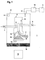
- Fig. 1 shows schematically the basic structure of a device 1 for aerosol production.
- the generated by means of the device 1 2 aerosol is in the present example to Cooling and lubrication of tools 3, workpieces as well as gearboxes and machines used.
- such devices 1 can also be used to generate Aerosols 2 for inhalers in medical technology, humidifiers in home appliances and the like can be used.
- the device according to FIG. 1 comprises a pressure vessel 4, in which an injector device 5 is arranged.
- the injector 5 is supplied via a first line 6 carrier gas and a second line 7, a liquid.
- the carrier gas consists of air and is provided via a compressed air supply, not shown, with a supply pressure P V , which is typically in the range 6 bar ⁇ P V ⁇ 10 bar.
- the liquid serves as a lubricant and is formed in the present embodiment of oil, which is fed via an oil reservoir in the conduit 7.
- synthetic esters or the like can be used.
- Both the air and the oil are each fed via a throttle 8, 9 of the injector 5.
- the throttling system forming throttles 8, 9 are controlled by a control unit 10.
- the control unit 10 is formed by an electric circuit or the like.
- the injector device 5 has an injector block 12, in which an injector chamber 13 is arranged.
- the injector chamber 13 is in the region of its outlet to the lower Widened towards the end.
- a conical impact body 14th arranged, whose lateral surface a stair structure with a multiplicity on each other following stages 15 has.
- a bracket 16 of the baffle 14 is at a predetermined distance to the outlet arranged the injector 13, this distance is preferably adjustable.
- the aerosol 2 with the fine oil particles is deflected laterally and via an aerosol outlet 17, which in the present example is arranged on the ceiling of the pressure vessel 4 is executed from this and fed to a tool 3.
- an aerosol outlet 17 which in the present example is arranged on the ceiling of the pressure vessel 4 is executed from this and fed to a tool 3.
- too several aerosol outlets 17 for connecting a predetermined number of tools 3 be provided.
- the heavy oil particles sink to the bottom of the pressure vessel 4, in which a Oil supply 18 is arranged, which is advantageously used as oil for aerosol production.
- Closure means 19 are provided between aerosol outlet 17 and tool 3 .
- the closure means 19 is preferably of formed a compressed air controlled ball valve. This can be done via the controller with short Response times are closed and opened, thereby reducing the supply of Aerosol 2 to the tool 3 can be abruptly activated and deactivated.
- FIG. 2 shows an exemplary embodiment of an injector device 5, which essentially corresponds to the embodiment of FIG. 1.
- the injector device 5 again an injector chamber 13, which is opposite the impact body 14 at a distance, wherein the baffle 14 by means of the holder 16 at a predetermined distance is fixed to the injector chamber 13.
- two nozzle sets each with two nozzles 20, 21, 22, 23 are provided, which for feeding air and oil into the injector device 5.
- the first nozzle set has two nozzles 20 that are close to the injector chamber 13, 21, wherein via the first nozzle 20 air and the second nozzle 21 oil in the injector 13 is headed.
- the second nozzle set is above the first nozzle set and also has one Nozzle 22 for supplying air and a second nozzle 23 for supplying oil.
- the supply of oil and air through the various nozzles is volume controlled via each one in Fig. 2, not shown throttle 8, 9, wherein the throttles 8, 9, the throttle system form.
- the air supply can be further adjusted become.
- the throttles 8, 9 of the throttle system are formed in the form of diaphragm assemblies.
- An embodiment of such formed as a diaphragm arrangement Throttle 8 for air supply is shown in Fig. 3.
- Such a diaphragm arrangement can regardless of the use of a differential pressure control in the aerosol generator be used.
- the diaphragm arrangement comprises a diaphragm body 24, in which at a distance next to each other lying a predetermined number of apertures 25 is incorporated.
- the apertures 25 each have a circular cross-section.
- the Diameter of the apertures 25 are preferably each formed differently and are in the range of less than one millimeter to a few millimeters.
- the shown in Fig. 3 aperture arrangement is used to supply air and has four side by side lying apertures 25 on. Before each aperture 25 is a Valve 26, via which air is supplied to the respective orifice 26.
- the diameters of the aperture 25 are large compared to the thickness of the visor body 24. In any case, the diameter amounts to at least one third of the thickness of the Visor body. Thus, the longitudinal extent of the aperture 25 is considerably smaller, but at least not much larger than their cross-section. This leads to even at different flow velocities of the air over the aperture cross section obtained a largely constant and homogeneous velocity profile becomes.
- each aperture assembly may be selectively accessed via the control unit 10 closed or opened.
- different cross sections of the throttle arise 8, 9, wherein in the present case fifteen different cross sections are adjustable.
- the aperture arrangements for oil supply have a structure which essentially the structure of the diaphragm assembly of FIG. 3 corresponds.
- the diaphragm arrangement for oil supply in the present case only two different apertures 25 on.
- the diaphragm arrangement for the additional air has three apertures in the present case 25 with different cross sections.
- control of the device 1 for aerosol production is carried out centrally via the control unit 10th
- the injector device 5 are supplied.
- the specification of these volume flows is dynamic Pressure control in the interior of the pressure vessel 4, in particular to a Self-stabilization of aerosol production leads.
- dynamic cross-sectional changes result of the aerosol sampling cross section and related changes the aerosol withdrawal amounts to a pressure change in the interior of the pressure vessel 4, which counteract the respective change in the withdrawal amount.
- the setting values of the throttle system are expediently as parameter values or Characteristics are stored in the control unit 10 or are entered as needed in this.
- the limit value ⁇ P 0 is in the range 2 bar ⁇ P 0 ⁇ 2.5 bar and is preferably 2.2 bar.
- the differential pressure is detected by the sensor 11 and read into the control unit 10 as an input of the control of aerosol production.
- the generation of aerosol is only resumed as soon as the differential pressure ⁇ P exceeds a further limit value ⁇ P 1 .
- the limit value ⁇ P 1 is above the limit value ⁇ P 0 .
- ⁇ P 1 is in the range 3 bar ⁇ ⁇ P 1 ⁇ 3.5 bar and is particularly advantageously 3.4 bar.
- the difference .DELTA.P between the limits .DELTA.P 0 and .DELTA.P 1 forms a switching hysteresis for the control of aerosol production, by which unnecessary switching operations, that is, starting and interrupting the aerosol generation, are avoided. This prevents the system from swinging up.
- the ball valve is actuated via an external control, whereby the aerosol delivery to the tool 3 can be abruptly activated and deactivated.
Landscapes
- Chemical & Material Sciences (AREA)
- Chemical Kinetics & Catalysis (AREA)
- Physics & Mathematics (AREA)
- Fluid Mechanics (AREA)
- Engineering & Computer Science (AREA)
- Mechanical Engineering (AREA)
- Nozzles (AREA)
- Air Humidification (AREA)
- Colloid Chemistry (AREA)
- Medicinal Preparation (AREA)
Abstract
Description
- Fig. 1:
- Blockschaltbild eines Ausführungsbeispiels der erfindungsgemäßen Vorrichtung zur Aerosolerzeugung.
- Fig. 2:
- Detaildarstellung eines Ausschnitts eines zweiten Ausführungsbeispiels einer Vorrichtung zur Aerosolerzeugung.
- Fig. 3:
- Ausführungsbeispiel einer Blendenanordnung für die Vorrichtung gemäß Fig. 1.
Claims (27)
- Vorrichtung (1) zur Aerosolerzeugung mit einer Injektorvorrichtung (5), in welcher aus einem Trägergas und einer Flüssigkeit ein Aerosol (2) erzeugt wird, wobei das Trägergas und die Flüssigkeit der Injektorvorrichtung (5) jeweils über ein Drosselsystem mengengesteuert zugeführt sind, dadurch gekennzeichnet, dass das Drosselsystem eine Blendenanordnung mit separat verschließbaren Blendenöffnungen (25) umfasst.
- Vorrichtung zur Aerosolerzeugung nach Anspruch 1, dadurch gekennzeichnet, dass das Drosselsystem wenigstens eine Drossel (8, 9) umfasst.
- Vorrichtung zur Aerosolerzeugung nach Anspruch 1 oder 2, dadurch gekennzeichnet, dass das Trägergas über wenigstens eine Düse (20) und die eine erste Drossel (8) bildende Blendenanordnung und die Flüssigkeit über wenigstens eine weitere Düse (21) und eine weitere Drossel (9) bildende Blendenanordnung der Injektorvorrichtung (5) zugeführt sind.
- Vorrichtung zur Aerosolerzeugung nach einem der oben genannten Ansprüche, dadurch gekennzeichnet, dass zwei Düsensätze mit jeweils einer Düse (20, 21, 22, 23) zur Zuführung von Trägergas und Flüssigkeit vorgesehen sind, wobei jeder Düse (20, 21, 22, 23) eine separate Blendenanordnung zugeordnet ist.
- Vorrichtung zur Aerosolerzeugung nach Anspruch 4, dadurch gekennzeichnet, dass eine Düse (22) mit einer vorgeordneten Blendenanordnung zur Zuführung von Zusatzträgergas vorgesehen ist.
- Vorrichtung zur Aerosolerzeugung nach einem der Ansprüche 2 bis 5, dadurch gekennzeichnet, dass jede Blendenanordnung eine vorgegebene Anzahl (N) von separat verschließbaren Blendenöffnungen (25) aufweist.
- Vorrichtung zur Aerosolerzeugung nach einem der Ansprüche 2 bis 6, dadurch gekennzeichnet, dass die Blendenöffnungen (25) einer Blendenanordnung jeweils verschiedene Durchmesser aufweisen.
- Vorrichtung zur Aerosolerzeugung nach einem der Ansprüche 2 bis 7, dadurch gekennzeichnet, dass der Durchmesser jeder Blendenöffnung (25) einer Blendenanordnung mindestens ein Drittel der Dicke des die Blendenöffnung (25) begrenzenden Blendenkörpers (24) beträgt.
- Vorrichtung zur Aerosolerzeugung nach einem der Ansprüche 2 bis 8, dadurch gekennzeichnet, dass jeder Blendenöffnung (25) einer Blendenanordnung über ein separates Ventil (26) Trägergas oder Flüssigkeit zugeführt ist.
- Vorrichtung zur Aerosolerzeugung nach einem der oben genannten Ansprüche, dadurch gekennzeichnet, dass dem Aerosolabgang (17) ein steuerbares Verschlussmittel (19) zugeordnet ist, durch dessen Betätigung die Förderung von Aerosol (2) über den Aerosolabgang (17) unterbunden ist.
- Vorrichtung zur Aerosolerzeugung nach Anspruch 10, dadurch gekennzeichnet, dass das Verschlussmittel (19) von einem gesteuerten Kugelhahn gebildet ist.
- Vorrichtung zur Aerosolerzeugung nach einem der oben genannten Ansprüche, dadurch gekennzeichnet, dass das Trägergas von Luft gebildet ist, und dass die Flüssigkeit von Öl oder einem synthetischen Ester gebildet ist.
- Vorrichtung zur Aerosolerzeugung nach einem der oben genannten Ansprüche, dadurch gekennzeichnet, dass die Injektorvorrichtung (5) in einem unter einem Behälterdruck (PB) stehenden Druckbehälter (4) angeordnet ist und das Trägergas unter einem Versorgungsdruck (PV) zugeführt ist und dass das Drosselsystem in Abhängigkeit vom Differenzdruck (ΔP=PV - PB) zwischen Behälterdruck und Versorgungsdruck steuerbar ausgestaltet ist.
- Vorrichtung zur Aerosolerzeugung nach einem der oben genannten Ansprüche, dadurch gekennzeichnet, dass das Drosselsystem über eine Steuereinheit (10) gesteuert ist.
- Vorrichtung zur Aerosolerzeugung nach Anspruch 13, dadurch gekennzeichnet, dass ein Sensor (11) zur Bestimmung des Differenzdruckes (ΔP = PV - PB) vorgesehen ist, welcher eine Eingangsgröße für die Steuereinheit (10) bildet.
- Verfahren zum Erzeugen eines Aerosols (2), bei dem in einer Injektorvorrichtung (5) ein Aerosol aus einem Trägergas und einer Flüssigkeit erzeugt wird, wobei die Menge des in die Injektorvorrichtung (5) zugeführten Trägergases und der in die Injektorvorrichtung (5) zugeführten Flüssigkeit gesteuert wird, dadurch gekennzeichnet, dass zur Mengensteuerung eine Mehrzahl von Blendenöffnungen (25) selektiv geöffnet oder geschlossen werden.
- Verfahren zum Erzeugen eines Aerosols nach Anspruch 16, dadurch gekennzeichnet, dass der Volumenstrom des Trägergases und der Flüssigkeit in Abhängigkeit von der Druckdifferenz (ΔP = PV - PB) zwischen einem Versorgungsdruck (PV) des Trägergases und einem Behälterdruck (PB) eines Druckbehälters (4), in dem die Injektorvorrichtung (3) angeordnet ist, gesteuert wird.
- Verfahren zum Erzeugen eines Aerosols nach Anspruch 16 oder 17, dadurch gekennzeichnet, dass über die Steuereinheit (10) Blendenöffnungen (25) einzeln geöffnet oder geschlossen werden.
- Verfahren zum Erzeugen eines Aerosols nach einem der Ansprüche 16 bis 18, dadurch gekennzeichnet, dass die Blendenöffnungen (25) der Blendenanordnungen durch die Steuereinheit (10) geschlossen werden, sobald der Differenzdruck (ΔP) einen ersten vorgegebenen Grenzwert (ΔP0) unterschreitet.
- Verfahren zum Erzeugen eines Aerosols nach Anspruch 19, dadurch gekennzeichnet, dass der erste Grenzwert (ΔP0) in einem Bereich zwischen 2 bar und 2,5 bar liegt.
- Verfahren zum Erzeugen eines Aerosols nach einem der Ansprüche 18 bis 20, dadurch gekennzeichnet, dass vorgegebene Blendenöffnungen (25) der Blendenanordnungen durch die Steuereinheit (10) geöffnet werden, sobald der Differenzdruck (ΔP) einen zweiten vorgegebenen Grenzwert (ΔP1) überschreitet, wobei der zweite vorgegebene Grenzwert (ΔP1) größer als der erste vorgegebene Grenzwert (ΔP0) ist.
- Verfahren zum Erzeugen eines Aerosols nach Anspruch 21, dadurch gekennzeichnet, dass der zweite Grenzwert (ΔP1) in einem Bereich zwischen 3 bar und 3,5 bar liegt.
- Verfahren zum Erzeugen eines Aerosols nach einem der Ansprüche 16 bis 21, dadurch gekennzeichnet, dass die Anzahl der geöffneten Blendenöffnungen (25) der einzelnen Blendenanordnungen bei oberhalb des Grenzwerts (ΔP0) liegenden Differenzdruck in Abhängigkeit der über wenigstens einen Aerosolabgang (17) aus dem Druckbehälter (4) geförderten Menge des Aerosols (2) über die Steuereinheit (10) vorgegeben wird.
- Verfahren zum Erzeugen eines Aerosols nach Anspruch 21, dadurch gekennzeichnet, dass die Blendenöffnungen (25) der einzelnen Blendenanordnungen in Abhängigkeit von Parameterwerten und/oder Kennlinien geöffnet werden.
- Verfahren zum Erzeugen eines Aerosols nach Anspruch 24, dadurch gekennzeichnet, dass die Parameterwerte und/oder Kennlinien in die Steuereinheit (10) eingegeben und/oder in dieser abgespeichert werden.
- Verfahren zum Erzeugen eines Aerosols nach einem der Ansprüche 16 bis 25, dadurch gekennzeichnet, dass das Aerosol (2) zur Kühlschmierung von Werkzeugen (3), Werkstücken und/oder Maschinenteilen eingesetzt wird.
- Verfahren zum Erzeugen eines Aerosols nach einem der Ansprüche 16 bis 26, dadurch gekennzeichnet, dass der Versorgungsdruck (PV) im Bereich zwischen 6 bar und 10 bar liegt.
Applications Claiming Priority (3)
| Application Number | Priority Date | Filing Date | Title |
|---|---|---|---|
| DE10104012A DE10104012C2 (de) | 2001-01-31 | 2001-01-31 | Vorrichtung zur Aerosolerzeugung |
| DE10104012 | 2001-01-31 | ||
| EP02718070A EP1355741B1 (de) | 2001-01-31 | 2002-01-31 | Vorrichtung und verfahren zur aerosolerzeugung |
Related Parent Applications (1)
| Application Number | Title | Priority Date | Filing Date |
|---|---|---|---|
| EP02718070A Division EP1355741B1 (de) | 2001-01-31 | 2002-01-31 | Vorrichtung und verfahren zur aerosolerzeugung |
Publications (3)
| Publication Number | Publication Date |
|---|---|
| EP1550511A2 true EP1550511A2 (de) | 2005-07-06 |
| EP1550511A3 EP1550511A3 (de) | 2005-09-21 |
| EP1550511B1 EP1550511B1 (de) | 2006-11-29 |
Family
ID=7672147
Family Applications (2)
| Application Number | Title | Priority Date | Filing Date |
|---|---|---|---|
| EP05007516A Expired - Lifetime EP1550511B1 (de) | 2001-01-31 | 2002-01-31 | Vorrichtung und Verfahren zur Aerosolerzeugung |
| EP02718070A Expired - Lifetime EP1355741B1 (de) | 2001-01-31 | 2002-01-31 | Vorrichtung und verfahren zur aerosolerzeugung |
Family Applications After (1)
| Application Number | Title | Priority Date | Filing Date |
|---|---|---|---|
| EP02718070A Expired - Lifetime EP1355741B1 (de) | 2001-01-31 | 2002-01-31 | Vorrichtung und verfahren zur aerosolerzeugung |
Country Status (9)
| Country | Link |
|---|---|
| US (1) | US20040124265A1 (de) |
| EP (2) | EP1550511B1 (de) |
| JP (1) | JP4017522B2 (de) |
| KR (1) | KR100508371B1 (de) |
| CN (1) | CN1278782C (de) |
| AT (2) | ATE309052T1 (de) |
| DE (4) | DE10164735C2 (de) |
| ES (1) | ES2276365T3 (de) |
| WO (1) | WO2002060592A1 (de) |
Families Citing this family (25)
| Publication number | Priority date | Publication date | Assignee | Title |
|---|---|---|---|---|
| DE10217927B4 (de) * | 2002-04-22 | 2005-05-12 | Grausam, Ingo | Einrichtung zur Erzeugung eines Aerosols |
| DE10310118A1 (de) * | 2003-03-06 | 2004-09-16 | Willy Vogel Ag | Schmiervorrichtung mit Einspritzeinrichtung und Schmierverfahren |
| DE10349642A1 (de) * | 2003-10-21 | 2005-05-19 | Bielomatik Leuze Gmbh + Co Kg | Vorrichtung zur Aerosolerzeugung und Injektoreinheit |
| KR100695122B1 (ko) * | 2003-11-29 | 2007-03-14 | 삼성전자주식회사 | 에어로졸의 밀도를 안정화하기 위한 장치 및 방법 |
| DE102005013458A1 (de) | 2004-04-20 | 2005-11-10 | ACCULUBE Manufacturing GmbH - Schmiermittel und -geräte - | Vorrichtung und Verfahren zur Bereitstellung eines feinen Ölnebels |
| DE102004050400A1 (de) * | 2004-10-15 | 2006-04-20 | Bernd Pfalz | Vorrichtung und Verfahren zum Mischen und Sprühen von Behandlungsmittel |
| US7086611B2 (en) * | 2004-10-19 | 2006-08-08 | Ingo Grausam | Device for producing an aerosol |
| FR2901157B1 (fr) * | 2006-05-19 | 2008-07-25 | Otv Sa | Injecteur de reactif destine a equiper un reacteur de traitement d'eau, comprenant une buse associee a un organe de dispersion, et dispositif de traitement d'eau correspondant |
| AT508319A1 (de) * | 2009-05-20 | 2010-12-15 | Mittermayr Alexander | Verfahren zur aromabehandlung eines in einer verpackung vorgesehenen lebensmittels |
| DE102009060454B8 (de) * | 2009-12-24 | 2018-10-18 | Hpm Technologie Gmbh | Vorrichtung zur Aerosolerzeugung |
| WO2012000049A1 (en) * | 2010-06-30 | 2012-01-05 | Commonwealth Scientific And Industrial Research Organisation | Droplet generation system and method |
| KR101389011B1 (ko) * | 2012-03-28 | 2014-04-24 | 주식회사 유니텍스 | 소스 컨테이너 및 기상 증착용 반응로 |
| CN103433166B (zh) * | 2013-08-23 | 2016-08-17 | 天能电池(芜湖)有限公司 | 雾化保湿装置 |
| EP2893986A1 (de) * | 2014-01-08 | 2015-07-15 | Siemens VAI Metals Technologies GmbH | Schmierung mit Spritzdüsen mit mehreren Öleintrittsöffnungen |
| CN105499047A (zh) * | 2016-01-22 | 2016-04-20 | 苏州市计量测试研究所 | 一种新型气溶胶雾化装置 |
| DE102016217268A1 (de) | 2016-09-09 | 2018-03-15 | Bielomatik Leuze Gmbh + Co. Kg | Düseneinheit, mobile Schmierungsvorrichtung und Verfahren zum Schmieren eines Objekts |
| DE102017209068A1 (de) | 2017-05-30 | 2018-12-06 | Bielomatik Leuze Gmbh + Co. Kg | Aerosolvorrichtung und Verfahren zum Bereitstellen eines Aerosols |
| JP7132706B2 (ja) * | 2017-10-06 | 2022-09-07 | 株式会社ディスコ | 汽水分離タンク |
| GB201819454D0 (en) | 2018-11-29 | 2019-01-16 | Johnson Matthey Plc | Apparatus and method for coating substrates with washcoats |
| GB201819455D0 (en) * | 2018-11-29 | 2019-01-16 | Johnson Matthey Plc | Apparatus and method for coating substrates with washcoats |
| KR102218659B1 (ko) * | 2019-06-28 | 2021-02-19 | 서울과학기술대학교 산학협력단 | 오일 미스트 분사장치 및 이를 포함하는 mql 시스템 |
| DE102020000903B4 (de) | 2020-02-19 | 2021-12-09 | Pieter Van Weenen & Co. Gmbh | Aerosolisierungsvorrichtung |
| KR102348753B1 (ko) * | 2021-01-12 | 2022-01-11 | 대한민국 | 유체 누출 대응 훈련용 유체 방출 키트 |
| KR102348761B1 (ko) * | 2021-01-12 | 2022-01-13 | 대한민국 | 유체 누출 대응 훈련용 유체 방출 장치 |
| DE102023104084A1 (de) * | 2023-02-20 | 2024-08-22 | Verein zur Förderung von Innovationen durch Forschung, Entwicklung und Technologietransfer e.V. (Verein INNOVENT e.V.) | Dosiereinheit und deren Verwendung |
Citations (8)
| Publication number | Priority date | Publication date | Assignee | Title |
|---|---|---|---|---|
| DE9205369U1 (de) | 1992-04-18 | 1993-08-19 | STO Verotec GmbH, 89415 Lauingen | Dämmelement für hinterlüftete Fassaden |
| DE19615379A1 (de) | 1996-04-18 | 1997-10-23 | Fraunhofer Ges Forschung | Pneumatische Handspritzpistole mit automatischer Spritzstrahlverstellung |
| WO1998010217A1 (de) | 1996-09-07 | 1998-03-12 | Pe Product Engineering Gmbh | Kühlschmiervorrichtung |
| DE19654321A1 (de) | 1996-12-24 | 1998-06-25 | Pe Product Engineering Gmbh | Vorrichtung zur Aerosolerzeugung |
| DE19721650A1 (de) | 1997-05-23 | 1998-11-26 | Pe Product Engineering Gmbh | Vorrichtung zur Aerosolerzeugung |
| EP0941769A1 (de) | 1996-11-29 | 1999-09-15 | Fuji Koeki Co., Ltd | Flüssigkeitsauftragvorrichtung |
| DE19917219A1 (de) | 1999-04-16 | 2000-10-26 | Unilube Ag Kreuzlingen | Verfahren der Schmierung und Schmiervorrichtung |
| EP1106902A1 (de) | 1998-08-14 | 2001-06-13 | Kuroda Seiko Company Limited | Nebelgenerator |
Family Cites Families (3)
| Publication number | Priority date | Publication date | Assignee | Title |
|---|---|---|---|---|
| BE558653A (de) * | ||||
| US2991939A (en) * | 1959-09-28 | 1961-07-11 | Barco Mfg Co Inc | Fluid mixing and spraying device |
| DE9205639U1 (de) * | 1992-04-25 | 1992-06-25 | Bombach, Jürgen, 7460 Balingen | Vorrichtung zum dosierten Versprühen, insbesondere von Klebstoff |
-
2001
- 2001-01-31 DE DE10164735A patent/DE10164735C2/de not_active Expired - Fee Related
- 2001-01-31 DE DE10104012A patent/DE10104012C2/de not_active Expired - Fee Related
-
2002
- 2002-01-31 WO PCT/EP2002/001004 patent/WO2002060592A1/de not_active Ceased
- 2002-01-31 AT AT02718070T patent/ATE309052T1/de not_active IP Right Cessation
- 2002-01-31 CN CNB028032489A patent/CN1278782C/zh not_active Expired - Fee Related
- 2002-01-31 JP JP2002560779A patent/JP4017522B2/ja not_active Expired - Fee Related
- 2002-01-31 DE DE50204857T patent/DE50204857D1/de not_active Expired - Fee Related
- 2002-01-31 DE DE50208872T patent/DE50208872D1/de not_active Expired - Fee Related
- 2002-01-31 AT AT05007516T patent/ATE346694T1/de not_active IP Right Cessation
- 2002-01-31 KR KR10-2003-7007333A patent/KR100508371B1/ko not_active Expired - Fee Related
- 2002-01-31 EP EP05007516A patent/EP1550511B1/de not_active Expired - Lifetime
- 2002-01-31 EP EP02718070A patent/EP1355741B1/de not_active Expired - Lifetime
- 2002-01-31 ES ES05007516T patent/ES2276365T3/es not_active Expired - Lifetime
- 2002-01-31 US US10/466,764 patent/US20040124265A1/en not_active Abandoned
Patent Citations (8)
| Publication number | Priority date | Publication date | Assignee | Title |
|---|---|---|---|---|
| DE9205369U1 (de) | 1992-04-18 | 1993-08-19 | STO Verotec GmbH, 89415 Lauingen | Dämmelement für hinterlüftete Fassaden |
| DE19615379A1 (de) | 1996-04-18 | 1997-10-23 | Fraunhofer Ges Forschung | Pneumatische Handspritzpistole mit automatischer Spritzstrahlverstellung |
| WO1998010217A1 (de) | 1996-09-07 | 1998-03-12 | Pe Product Engineering Gmbh | Kühlschmiervorrichtung |
| EP0941769A1 (de) | 1996-11-29 | 1999-09-15 | Fuji Koeki Co., Ltd | Flüssigkeitsauftragvorrichtung |
| DE19654321A1 (de) | 1996-12-24 | 1998-06-25 | Pe Product Engineering Gmbh | Vorrichtung zur Aerosolerzeugung |
| DE19721650A1 (de) | 1997-05-23 | 1998-11-26 | Pe Product Engineering Gmbh | Vorrichtung zur Aerosolerzeugung |
| EP1106902A1 (de) | 1998-08-14 | 2001-06-13 | Kuroda Seiko Company Limited | Nebelgenerator |
| DE19917219A1 (de) | 1999-04-16 | 2000-10-26 | Unilube Ag Kreuzlingen | Verfahren der Schmierung und Schmiervorrichtung |
Also Published As
| Publication number | Publication date |
|---|---|
| EP1355741A1 (de) | 2003-10-29 |
| JP4017522B2 (ja) | 2007-12-05 |
| DE50208872D1 (de) | 2007-01-11 |
| CN1477999A (zh) | 2004-02-25 |
| KR20030065531A (ko) | 2003-08-06 |
| ES2276365T3 (es) | 2007-06-16 |
| EP1550511B1 (de) | 2006-11-29 |
| CN1278782C (zh) | 2006-10-11 |
| EP1550511A3 (de) | 2005-09-21 |
| DE10104012A1 (de) | 2002-08-22 |
| KR100508371B1 (ko) | 2005-08-17 |
| EP1355741B1 (de) | 2005-11-09 |
| DE10104012C2 (de) | 2003-05-28 |
| JP2004531366A (ja) | 2004-10-14 |
| DE50204857D1 (de) | 2005-12-15 |
| WO2002060592A1 (de) | 2002-08-08 |
| ATE309052T1 (de) | 2005-11-15 |
| DE10164735C2 (de) | 2003-05-15 |
| ATE346694T1 (de) | 2006-12-15 |
| DE10164735A1 (de) | 2003-01-16 |
| US20040124265A1 (en) | 2004-07-01 |
Similar Documents
| Publication | Publication Date | Title |
|---|---|---|
| EP1550511B1 (de) | Vorrichtung und Verfahren zur Aerosolerzeugung | |
| EP2303465B1 (de) | Beschichtungsvorrichtung | |
| DE1775698A1 (de) | OElvernebler | |
| WO1998028085A1 (de) | Vorrichtung zur aerosolerzeugung | |
| EP1675688B1 (de) | Verfahren zur aerosolerzeugung und injektoreinheit | |
| DE602004012985T2 (de) | Zerstäubungsdüse für überhitzte flüssigkeiten | |
| DE102009060454B4 (de) | Vorrichtung zur Aerosolerzeugung | |
| EP3956073B1 (de) | Verschliessbare düse | |
| DE3028125A1 (de) | Schmiermittelverteiler | |
| DE112005001691T5 (de) | Anordnung und Verfahren zum Steuern bzw. Regeln der Ableitung von Kohlendioxid für Klimaanlagensysteme | |
| DE20122041U1 (de) | Vorrichtung zur Aerosolerzeugung | |
| DE19917219B4 (de) | Schmiervorrichtung | |
| EP3623032B1 (de) | Filtersystem mit direkter reinigungslufteinspritzung sowie verfahren zum abreinigen | |
| DE4002846C2 (de) | ||
| DE20121334U1 (de) | Vorrichtung zur Aerosolerzeugung | |
| EP1259332A1 (de) | Verfahren und leitungssystem zur beeinflussung des tropfenspektrums von fluiden stoffen bei deren zerstäubung | |
| EP1252005B1 (de) | Injektionsdüse für mischköpfe von reaktionsgiessmaschinen | |
| EP1054738B1 (de) | Nebelgeneratorkopf | |
| DE10352947A1 (de) | Verfahren und Vorrichtung zur Aerosolerzeugung mittels Trägergas-Drucksteuerung | |
| EP1419339A1 (de) | Verfahren und vorrichtung zum nebelschmieren von schmierstellen mit schmierstoff-minimalmengen | |
| DE10251082A1 (de) | Vorrichtung und Verfahren zur Erzeugung eines Flüssigkeit-Gas-Gemisches, insbesondere eines Aerosols | |
| WO2003090935A1 (de) | Vorrichtung zur erzeugung eines aerosols | |
| EP4729178A1 (de) | System zum reproduzierbaren aufbringen von temporär wirkenden oberflächenreinigungs- oder funktionsbeschichtungen | |
| DE102024127632A1 (de) | System zum reproduzierbaren Aufbringen von temporär wirkenden Oberflächenreinigungs- oder Funktionsbeschichtungen | |
| DE1632430B2 (de) | Einrichtung zum Vermischen eines unter Druck stehenden Gasstroms mit einem feinverteilten Nebel eines flüssigen Mittels, beispielsweise Schmieröls |
Legal Events
| Date | Code | Title | Description |
|---|---|---|---|
| PUAI | Public reference made under article 153(3) epc to a published international application that has entered the european phase |
Free format text: ORIGINAL CODE: 0009012 |
|
| AC | Divisional application: reference to earlier application |
Ref document number: 1355741 Country of ref document: EP Kind code of ref document: P |
|
| AK | Designated contracting states |
Kind code of ref document: A2 Designated state(s): AT BE CH CY DE DK ES FI FR GB GR IE IT LI LU MC NL PT SE TR |
|
| PUAL | Search report despatched |
Free format text: ORIGINAL CODE: 0009013 |
|
| AK | Designated contracting states |
Kind code of ref document: A3 Designated state(s): AT BE CH CY DE DK ES FI FR GB GR IE IT LI LU MC NL PT SE TR |
|
| 17P | Request for examination filed |
Effective date: 20060307 |
|
| GRAP | Despatch of communication of intention to grant a patent |
Free format text: ORIGINAL CODE: EPIDOSNIGR1 |
|
| AKX | Designation fees paid |
Designated state(s): AT BE CH CY DE DK ES FI FR GB GR IE IT LI LU MC NL PT SE TR |
|
| GRAS | Grant fee paid |
Free format text: ORIGINAL CODE: EPIDOSNIGR3 |
|
| GRAA | (expected) grant |
Free format text: ORIGINAL CODE: 0009210 |
|
| AC | Divisional application: reference to earlier application |
Ref document number: 1355741 Country of ref document: EP Kind code of ref document: P |
|
| AK | Designated contracting states |
Kind code of ref document: B1 Designated state(s): AT BE CH CY DE DK ES FI FR GB GR IE IT LI LU MC NL PT SE TR |
|
| PG25 | Lapsed in a contracting state [announced via postgrant information from national office to epo] |
Ref country code: FI Free format text: LAPSE BECAUSE OF FAILURE TO SUBMIT A TRANSLATION OF THE DESCRIPTION OR TO PAY THE FEE WITHIN THE PRESCRIBED TIME-LIMIT Effective date: 20061129 Ref country code: IE Free format text: LAPSE BECAUSE OF FAILURE TO SUBMIT A TRANSLATION OF THE DESCRIPTION OR TO PAY THE FEE WITHIN THE PRESCRIBED TIME-LIMIT Effective date: 20061129 |
|
| REG | Reference to a national code |
Ref country code: GB Ref legal event code: FG4D Free format text: NOT ENGLISH |
|
| REG | Reference to a national code |
Ref country code: CH Ref legal event code: NV Representative=s name: BOVARD AG PATENTANWAELTE Ref country code: CH Ref legal event code: EP |
|
| REG | Reference to a national code |
Ref country code: IE Ref legal event code: FG4D Free format text: LANGUAGE OF EP DOCUMENT: GERMAN |
|
| REF | Corresponds to: |
Ref document number: 50208872 Country of ref document: DE Date of ref document: 20070111 Kind code of ref document: P |
|
| PGFP | Annual fee paid to national office [announced via postgrant information from national office to epo] |
Ref country code: CH Payment date: 20070125 Year of fee payment: 6 |
|
| PGFP | Annual fee paid to national office [announced via postgrant information from national office to epo] |
Ref country code: SE Payment date: 20070129 Year of fee payment: 6 |
|
| PG25 | Lapsed in a contracting state [announced via postgrant information from national office to epo] |
Ref country code: MC Free format text: LAPSE BECAUSE OF NON-PAYMENT OF DUE FEES Effective date: 20070131 |
|
| PGFP | Annual fee paid to national office [announced via postgrant information from national office to epo] |
Ref country code: AT Payment date: 20070131 Year of fee payment: 6 Ref country code: ES Payment date: 20070131 Year of fee payment: 6 Ref country code: NL Payment date: 20070131 Year of fee payment: 6 |
|
| REG | Reference to a national code |
Ref country code: SE Ref legal event code: TRGR |
|
| PGFP | Annual fee paid to national office [announced via postgrant information from national office to epo] |
Ref country code: DE Payment date: 20070227 Year of fee payment: 6 |
|
| PG25 | Lapsed in a contracting state [announced via postgrant information from national office to epo] |
Ref country code: DK Free format text: LAPSE BECAUSE OF FAILURE TO SUBMIT A TRANSLATION OF THE DESCRIPTION OR TO PAY THE FEE WITHIN THE PRESCRIBED TIME-LIMIT Effective date: 20070228 |
|
| PG25 | Lapsed in a contracting state [announced via postgrant information from national office to epo] |
Ref country code: PT Free format text: LAPSE BECAUSE OF FAILURE TO SUBMIT A TRANSLATION OF THE DESCRIPTION OR TO PAY THE FEE WITHIN THE PRESCRIBED TIME-LIMIT Effective date: 20070430 |
|
| ET | Fr: translation filed | ||
| REG | Reference to a national code |
Ref country code: ES Ref legal event code: FG2A Ref document number: 2276365 Country of ref document: ES Kind code of ref document: T3 |
|
| GBV | Gb: ep patent (uk) treated as always having been void in accordance with gb section 77(7)/1977 [no translation filed] |
Effective date: 20061129 |
|
| REG | Reference to a national code |
Ref country code: IE Ref legal event code: FD4D |
|
| PLBE | No opposition filed within time limit |
Free format text: ORIGINAL CODE: 0009261 |
|
| STAA | Information on the status of an ep patent application or granted ep patent |
Free format text: STATUS: NO OPPOSITION FILED WITHIN TIME LIMIT |
|
| 26N | No opposition filed |
Effective date: 20070830 |
|
| PG25 | Lapsed in a contracting state [announced via postgrant information from national office to epo] |
Ref country code: GB Free format text: LAPSE BECAUSE OF FAILURE TO SUBMIT A TRANSLATION OF THE DESCRIPTION OR TO PAY THE FEE WITHIN THE PRESCRIBED TIME-LIMIT Effective date: 20061129 |
|
| BERE | Be: lapsed |
Owner name: WILLY VOGEL A.G. Effective date: 20070131 |
|
| PG25 | Lapsed in a contracting state [announced via postgrant information from national office to epo] |
Ref country code: BE Free format text: LAPSE BECAUSE OF NON-PAYMENT OF DUE FEES Effective date: 20070131 |
|
| PGFP | Annual fee paid to national office [announced via postgrant information from national office to epo] |
Ref country code: IT Payment date: 20070628 Year of fee payment: 6 |
|
| PG25 | Lapsed in a contracting state [announced via postgrant information from national office to epo] |
Ref country code: GR Free format text: LAPSE BECAUSE OF FAILURE TO SUBMIT A TRANSLATION OF THE DESCRIPTION OR TO PAY THE FEE WITHIN THE PRESCRIBED TIME-LIMIT Effective date: 20070301 |
|
| PGFP | Annual fee paid to national office [announced via postgrant information from national office to epo] |
Ref country code: FR Payment date: 20070125 Year of fee payment: 6 |
|
| REG | Reference to a national code |
Ref country code: CH Ref legal event code: PL |
|
| NLV4 | Nl: lapsed or anulled due to non-payment of the annual fee |
Effective date: 20080801 |
|
| EUG | Se: european patent has lapsed | ||
| PG25 | Lapsed in a contracting state [announced via postgrant information from national office to epo] |
Ref country code: CH Free format text: LAPSE BECAUSE OF NON-PAYMENT OF DUE FEES Effective date: 20080131 Ref country code: DE Free format text: LAPSE BECAUSE OF NON-PAYMENT OF DUE FEES Effective date: 20080801 Ref country code: LI Free format text: LAPSE BECAUSE OF NON-PAYMENT OF DUE FEES Effective date: 20080131 Ref country code: NL Free format text: LAPSE BECAUSE OF NON-PAYMENT OF DUE FEES Effective date: 20080801 |
|
| PG25 | Lapsed in a contracting state [announced via postgrant information from national office to epo] |
Ref country code: AT Free format text: LAPSE BECAUSE OF NON-PAYMENT OF DUE FEES Effective date: 20080131 |
|
| REG | Reference to a national code |
Ref country code: FR Ref legal event code: ST Effective date: 20081029 |
|
| PG25 | Lapsed in a contracting state [announced via postgrant information from national office to epo] |
Ref country code: SE Free format text: LAPSE BECAUSE OF NON-PAYMENT OF DUE FEES Effective date: 20080201 |
|
| REG | Reference to a national code |
Ref country code: ES Ref legal event code: FD2A Effective date: 20080201 |
|
| PG25 | Lapsed in a contracting state [announced via postgrant information from national office to epo] |
Ref country code: FR Free format text: LAPSE BECAUSE OF NON-PAYMENT OF DUE FEES Effective date: 20080131 |
|
| PG25 | Lapsed in a contracting state [announced via postgrant information from national office to epo] |
Ref country code: ES Free format text: LAPSE BECAUSE OF NON-PAYMENT OF DUE FEES Effective date: 20080201 |
|
| PG25 | Lapsed in a contracting state [announced via postgrant information from national office to epo] |
Ref country code: CY Free format text: LAPSE BECAUSE OF FAILURE TO SUBMIT A TRANSLATION OF THE DESCRIPTION OR TO PAY THE FEE WITHIN THE PRESCRIBED TIME-LIMIT Effective date: 20061129 Ref country code: IT Free format text: LAPSE BECAUSE OF NON-PAYMENT OF DUE FEES Effective date: 20080131 Ref country code: LU Free format text: LAPSE BECAUSE OF NON-PAYMENT OF DUE FEES Effective date: 20070131 |
|
| PG25 | Lapsed in a contracting state [announced via postgrant information from national office to epo] |
Ref country code: TR Free format text: LAPSE BECAUSE OF FAILURE TO SUBMIT A TRANSLATION OF THE DESCRIPTION OR TO PAY THE FEE WITHIN THE PRESCRIBED TIME-LIMIT Effective date: 20061129 |