EP1548858B1 - Batteriekühlungsstruktur - Google Patents
Batteriekühlungsstruktur Download PDFInfo
- Publication number
- EP1548858B1 EP1548858B1 EP20040029576 EP04029576A EP1548858B1 EP 1548858 B1 EP1548858 B1 EP 1548858B1 EP 20040029576 EP20040029576 EP 20040029576 EP 04029576 A EP04029576 A EP 04029576A EP 1548858 B1 EP1548858 B1 EP 1548858B1
- Authority
- EP
- European Patent Office
- Prior art keywords
- cooling air
- battery
- air guide
- cooling
- plates
- Prior art date
- Legal status (The legal status is an assumption and is not a legal conclusion. Google has not performed a legal analysis and makes no representation as to the accuracy of the status listed.)
- Expired - Lifetime
Links
- 238000001816 cooling Methods 0.000 title claims description 250
- 238000011144 upstream manufacturing Methods 0.000 claims description 13
- 230000007423 decrease Effects 0.000 claims description 8
- 230000001965 increasing effect Effects 0.000 claims description 5
- 230000003247 decreasing effect Effects 0.000 description 22
- 230000000694 effects Effects 0.000 description 21
- 238000010586 diagram Methods 0.000 description 14
- 230000003014 reinforcing effect Effects 0.000 description 5
- 230000000052 comparative effect Effects 0.000 description 4
- 230000015556 catabolic process Effects 0.000 description 3
- 238000006731 degradation reaction Methods 0.000 description 3
- 238000007664 blowing Methods 0.000 description 2
- 239000012141 concentrate Substances 0.000 description 2
- 230000012447 hatching Effects 0.000 description 2
- 229910005813 NiMH Inorganic materials 0.000 description 1
- 238000007600 charging Methods 0.000 description 1
- 238000007599 discharging Methods 0.000 description 1
- 230000002708 enhancing effect Effects 0.000 description 1
- 229920003002 synthetic resin Polymers 0.000 description 1
- 239000000057 synthetic resin Substances 0.000 description 1
Images


Classifications
-
- H—ELECTRICITY
- H01—ELECTRIC ELEMENTS
- H01M—PROCESSES OR MEANS, e.g. BATTERIES, FOR THE DIRECT CONVERSION OF CHEMICAL ENERGY INTO ELECTRICAL ENERGY
- H01M10/00—Secondary cells; Manufacture thereof
- H01M10/60—Heating or cooling; Temperature control
- H01M10/65—Means for temperature control structurally associated with the cells
- H01M10/655—Solid structures for heat exchange or heat conduction
- H01M10/6556—Solid parts with flow channel passages or pipes for heat exchange
- H01M10/6557—Solid parts with flow channel passages or pipes for heat exchange arranged between the cells
-
- H—ELECTRICITY
- H01—ELECTRIC ELEMENTS
- H01M—PROCESSES OR MEANS, e.g. BATTERIES, FOR THE DIRECT CONVERSION OF CHEMICAL ENERGY INTO ELECTRICAL ENERGY
- H01M10/00—Secondary cells; Manufacture thereof
- H01M10/60—Heating or cooling; Temperature control
- H01M10/61—Types of temperature control
- H01M10/613—Cooling or keeping cold
-
- H—ELECTRICITY
- H01—ELECTRIC ELEMENTS
- H01M—PROCESSES OR MEANS, e.g. BATTERIES, FOR THE DIRECT CONVERSION OF CHEMICAL ENERGY INTO ELECTRICAL ENERGY
- H01M10/00—Secondary cells; Manufacture thereof
- H01M10/60—Heating or cooling; Temperature control
- H01M10/61—Types of temperature control
- H01M10/617—Types of temperature control for achieving uniformity or desired distribution of temperature
-
- H—ELECTRICITY
- H01—ELECTRIC ELEMENTS
- H01M—PROCESSES OR MEANS, e.g. BATTERIES, FOR THE DIRECT CONVERSION OF CHEMICAL ENERGY INTO ELECTRICAL ENERGY
- H01M10/00—Secondary cells; Manufacture thereof
- H01M10/60—Heating or cooling; Temperature control
- H01M10/64—Heating or cooling; Temperature control characterised by the shape of the cells
- H01M10/643—Cylindrical cells
-
- H—ELECTRICITY
- H01—ELECTRIC ELEMENTS
- H01M—PROCESSES OR MEANS, e.g. BATTERIES, FOR THE DIRECT CONVERSION OF CHEMICAL ENERGY INTO ELECTRICAL ENERGY
- H01M10/00—Secondary cells; Manufacture thereof
- H01M10/60—Heating or cooling; Temperature control
- H01M10/65—Means for temperature control structurally associated with the cells
- H01M10/656—Means for temperature control structurally associated with the cells characterised by the type of heat-exchange fluid
- H01M10/6561—Gases
- H01M10/6566—Means within the gas flow to guide the flow around one or more cells, e.g. manifolds, baffles or other barriers
-
- H—ELECTRICITY
- H01—ELECTRIC ELEMENTS
- H01M—PROCESSES OR MEANS, e.g. BATTERIES, FOR THE DIRECT CONVERSION OF CHEMICAL ENERGY INTO ELECTRICAL ENERGY
- H01M50/00—Constructional details or processes of manufacture of the non-active parts of electrochemical cells other than fuel cells, e.g. hybrid cells
- H01M50/20—Mountings; Secondary casings or frames; Racks, modules or packs; Suspension devices; Shock absorbers; Transport or carrying devices; Holders
- H01M50/204—Racks, modules or packs for multiple batteries or multiple cells
- H01M50/207—Racks, modules or packs for multiple batteries or multiple cells characterised by their shape
- H01M50/213—Racks, modules or packs for multiple batteries or multiple cells characterised by their shape adapted for cells having curved cross-section, e.g. round or elliptic
-
- H—ELECTRICITY
- H01—ELECTRIC ELEMENTS
- H01M—PROCESSES OR MEANS, e.g. BATTERIES, FOR THE DIRECT CONVERSION OF CHEMICAL ENERGY INTO ELECTRICAL ENERGY
- H01M10/00—Secondary cells; Manufacture thereof
- H01M10/60—Heating or cooling; Temperature control
- H01M10/62—Heating or cooling; Temperature control specially adapted for specific applications
- H01M10/625—Vehicles
-
- Y—GENERAL TAGGING OF NEW TECHNOLOGICAL DEVELOPMENTS; GENERAL TAGGING OF CROSS-SECTIONAL TECHNOLOGIES SPANNING OVER SEVERAL SECTIONS OF THE IPC; TECHNICAL SUBJECTS COVERED BY FORMER USPC CROSS-REFERENCE ART COLLECTIONS [XRACs] AND DIGESTS
- Y02—TECHNOLOGIES OR APPLICATIONS FOR MITIGATION OR ADAPTATION AGAINST CLIMATE CHANGE
- Y02E—REDUCTION OF GREENHOUSE GAS [GHG] EMISSIONS, RELATED TO ENERGY GENERATION, TRANSMISSION OR DISTRIBUTION
- Y02E60/00—Enabling technologies; Technologies with a potential or indirect contribution to GHG emissions mitigation
- Y02E60/10—Energy storage using batteries
Definitions
- the present invention relates to a battery cooling structure in which a large number of rod-shaped battery modules are arranged in parallel to each other at predetermined intervals within a battery case, and these large number of battery modules are cooled with cooling air.
- Japanese Patent Application Laid-open Nos. 10-255859 and 11-329518 disclose an arrangement in which a long rod-shaped battery module is formed by connecting a plurality of battery elements together in series, and a large number of the battery modules are arranged in parallel to each other at predetermined intervals within a battery case, the arrangement being employed as an energy source for a motor for travel of an electric automobile. Since these battery modules generate heat during charging and discharging, cooling is carried out by passing cooling air from a cooling air inlet at the front end of the battery case to a cooling air outlet at the rear end.
- the battery modules on the front vertical row side are cooled efficiently by contact with low temperature cooling air that has not yet carried out heat exchange, but the battery modules on the rear vertical row side contact cooling air whose temperature has been increased by heat exchange, so that they have difficulty to be cooled.
- the cooling effect to the battery modules in a middle tier which are far from an inner face of the battery case, is degraded. In this way, the difference in cooling effect causes a variation in the temperature of the battery modules, leading to a problem that the capacity decreases or the durability is degraded.
- low temperature cooling air is replenished by connecting a bypass passage to a middle part, in the direction of flow of cooling air, of the battery case, and in the arrangement disclosed in Japanese Patent Application Laid-open No. 11-329518 , the variation in the temperature is eliminated by replenishing low temperature cooling air via an opening formed in a middle part, in the direction of flow of cooling air, of the battery case so as to uniformly cool the battery modules on the upstream side and on the downstream side in the direction of flow of cooling air.
- providing the bypass passage for introducing the cooling air gives rise to a problem that the structure of the battery case becomes complicated or the dimensions thereof increase, and providing the opening for introducing the cooling air also gives rise to a problem that the layout of the battery case is restricted in order not to block the opening.
- JP 2000-133225 A on which the preamble of claim 1 is based, figure 1 , the distance between the batteries 2 and the plurality of separate flow restricting ribs 5 mounted on the upper and lower casing plates decreases in the flow direction.
- a plurality of flow restricting ribs 5 are separately mounted to the upper and lower casing plates.
- Figure 7d shows a plurality of separate V-shaped tapered portions on the vertical casing plates facing axial ends of the batteries.
- figure 5 shows a flow path channel members 22 on bottom surfaces of the bottom plate of the battery casing 12, and tapered in the flow direction.
- Figures 19 and 20 show a flow path channel member 132 mounted on the bottom surface of the bottom plate of the battery casing 112 and provided with V-shaped flow channels formed therein. Since both flow plate channels members 22, 132 are mounted to the bottom surface of the bottom plate of the casing, the bottom plate of the casing is provided with cooling air slits for passing air from the flow part channel members 22, 132 into the casing. These air slits will weaken the battery casing and increase the air flow resistance.
- the present invention has been accomplished under the above-mentioned circumstances, and it is an object thereof to uniformly cool a large number of battery modules while simplifying the battery case, reducing the dimensions thereof and ensuring a degree of freedom in the layout.
- the battery cooling structure wherein the cooling air guide channel has a substantially V-shaped tapered portion whose channel width decreases from the upstream side to the downstream side of the flow of cooling air.
- the battery cooling structure wherein the depth of the cooling air guide channel is different between one second plate and the other second plate.
- the battery cooling structure wherein the position of the downstream end, in the direction of flow of cooling air, of the cooling air guide channel is different between one second plate and the other second plate.
- the battery cooling structure wherein the further toward the downstream side of the flow of cooling air the shallower the depth of the cooling air guide channel of at least one of the second plates.
- the battery cooling structure wherein one of the second plates is provided with the cooling air guide channel, and the other second plate is provided with a protruding portion that faces the cooling air guide channel.
- the battery cooling structure wherein at least one of the second plates has a plurality of cooling air guide channels arranged side by side in a direction perpendicular to the direction of flow of cooling air.
- the battery cooling structure wherein the battery module includes a plurality of battery elements connected together in series, and the downstream ends, in the direction of flow of cooling air, of the plurality of cooling air guide channels are oriented toward a section in which the battery elements are connected.
- the battery cooling structure wherein the cooling air guide channel has an enlarged portion on the upstream side, in the direction of flow of cooling air, in the tapered portion, the enlarged portion having an increased channel width.
- the battery cooling structure wherein an inner face of at least one of the pair of second plates has formed thereon a projecting portion that simulates the shape and the arrangement of the battery modules.
- the battery cooling structure wherein a flow-regulating member for suppressing contact of cooling air with the battery modules in the foremost vertical row is provided in the cooling air inlet of the battery case.
- the battery case housing the large number of rod-shaped battery modules arranged in parallel to each other at predetermined intervals is formed into the shape of a rectangular tube having the cooling air inlet and the cooling air outlet by means of the pair of first plates that support opposite ends of the battery modules and the pair of second plates that are combined with the pair of first plates; when cooling the battery modules by passing cooling air from the cooling air inlet to the cooling air outlet, since the inner face of at least one of the pair of second plates is provided with the cooling air guide channel whose flow-path cross sectional area decreases from the cooling air inlet side to the cooling air outlet side, it is possible to deflect the flow of cooling air by means of this cooling air guide channel toward a central part on the downstream side of the battery case, thereby effectively cooling the battery modules that receive a poor cooling effect as being disposed in a central part on the downstream side, and making uniform the temperature of the large number of battery modules so as to suppress variation in capacity and lifetime.
- the cooling air guide channel has the substantially V-shaped tapered portion whose channel width decreases from the upstream side to the downstream side of the flow of cooling air, this tapered portion pushes the cooling air out of the cooling air guide channel, thereby effectively deflecting the cooling air toward the central part on the downstream side of the battery case.
- the depth of the cooling air guide channel is different between the two second plates, it is possible to make nonuniform the amounts of cooling air deflected from the two cooling air guide channels to the central part on the downstream side of the battery case, thus avoiding degradation of the cooling effect by the cooling air flows which are combined in the central part on the downstream side of the battery case to counteract each other.
- one of the second plates is provided with the cooling air guide channel, and the other is provided with the protruding portion, it is possible to smoothly deflect the cooling air from one of the second plates to the other, thus effectively cooling the battery modules disposed in the central part on the downstream side of the battery case.
- the seventh aspect since at least one of the second plates is provided with the plurality of cooling air guide channels arranged side by side in the direction perpendicular to the direction of flow of cooling air, it is possible to deflect the cooling air at any position in the direction perpendicular to the direction of flow of cooling air.
- downstream ends, in the direction of flow of cooling air, of the plurality of cooling air guide channels are oriented to the section in which the plurality of battery elements forming the battery module are connected, it is possible to concentrate the cooling air on an area of the battery modules where heat is generated.
- the enlarged portion having the increased channel width is provided on the upstream side of the tapered portion of the cooling air guide channel, it is possible to minutely control the distribution of the amount of cooling air deflected in the direction perpendicular to the direction of flow of the cooling air.
- the inner face of at least one of the pair of second plates has formed thereon the projecting portion that simulates the shape and the arrangement of the battery modules, it is possible to deflect the cooling air that collides with the projecting portion toward the central part of the battery case, thereby further enhancing the effect of deflecting the cooling air in the cooling air guide channel.
- the flow-regulating member is provided in the cooling air inlet of the battery case, it is possible to suppress the contact of cooling air with the battery modules in the foremost vertical row, which are the most easily cooled, thereby reducing the difference in temperature from the battery modules that are difficult to cool.
- FIGS. 1 to 4C A first embodiment is now explained with reference to FIGS. 1 to 4C .
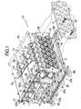
- a battery module 11 which serves as a power source for a hybrid vehicle motor/generator, is formed by integrally connecting together in series a plurality (six in this embodiment) of cylindrical battery elements 12 made of, for example, NiMH batteries into a rod shape, and twenty battery modules 11 are arranged in a staggered manner so that there are seven in an upper tier, six in a middle tier, and seven in a lower tier.
- a battery case 13 for supporting the 20 battery modules 11 is made in the shape of substantially rectangular tube having a pair of rectangular first plates 14 forming left and right side faces of the battery case 13 and a pair of second plates 15 providing a horizontal connection between upper ends and between lower ends of the two first plates 14.
- Front and rear ends of the substantially rectangular tube-shaped battery case 13 are open; the front end is provided with a cooling air inlet 16 (see FIG. 4A ), and the rear end is provided with a cooling air outlet 17 (see FIG. 4A ). Cooling air is supplied to the cooling air inlet 16 via a cooling fan, which is not illustrated.
- a pair of front and rear support members 18 and a pair of upper and lower beam members 19 are combined into a frame. These four frames, while being arranged between the pair of second plates 15 in the front-to-rear direction, are secured by four bolts 21 running through reinforcing members 20 reinforcing upper and lower faces of the pair of second plates 15 at the front end, and are also secured by four bolts 21 running through reinforcing members 20 reinforcing upper and lower faces of the pair of second plates 15 at the rear end.
- the pair of first plates 14 are each secured to side faces of the pair of second plates 15 and left and right ends of the support members 18 via six bolts 22.
- the seven battery modules 11 in the upper tier and the seven battery modules 11 in the lower tier are positioned by being fitted in wave-shaped depressions on inner faces of the support members 18 and the beam members 19 that are combined into the frame. Opposite ends of all of the battery modules 11, including the six battery modules 11 in the middle tier, are positioned by being fitted into openings formed in the pair of first plates 14.
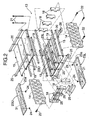
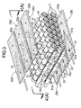
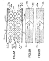
- Three synthetic resin air guide plates 23U and 23L are secured to an inner face of each second plate 15 by two bolts 24 per air guide plate.
- a cooling air guide channel 31 formed from a fixed width parallel portion 31 a positioned on the cooling air inlet 16 side, and a tapered portion 31 b which is positioned on the cooling air outlet 17 side and is tapered into a V-shape toward the rear.
- a bank-shaped projection 23a is formed on an end portion of each of the air guide plates 23U and 23L on the cooling air outlet 17 side.
- the battery modules 11 discharge.
- the battery modules 11 are charged.
- cooling air is supplied into the cooling air inlet 16 via a cooling fan, which is not illustrated, so as to cool the battery modules 11.
- the cooling air supplied into the cooling air inlet 16 is deflected up and down by the three tiers of flow-regulating members 25 arranged in front of the three battery modules 11 in the foremost vertical row; forced to flow in spaces formed between the pair of second plates 15 and the battery modules 11 while avoiding direct collision with the three battery modules 11 in the foremost vertical row; and discharged through the cooling air outlet 17.
- the flow-regulating members 25 prevent the cooling air from colliding with the battery modules 11 in the foremost vertical row and being disturbed, and have the function of suppressing cooling of the battery modules 11 in the foremost vertical row, which are the most easily cooled, thus decreasing the difference in temperature from the other battery modules 11.
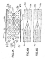
- the cooling air flowing through the tapered cooling air guide channels 31 of the six air guide plates 23U and 23L provided on the inner faces of the pair of second plates 15 is guided toward the battery modules 11 in the middle tier from the vicinity of a middle part in the front-to-rear direction of the battery case 13, because the flow-path cross sectional area of the tapered portion 31b of each of the cooling air guide channels 31 narrows as it goes toward the downstream side. Therefore, it is possible to effectively cool the three battery modules 11 for which the cooling efficiency is low and which are shown by the hatching in FIG. 4A , thus suppressing increase in temperature thereof and to prevent degradation in performance.
- Table 1 shows a comparison of the effects of a comparative example and embodiments (first embodiment to tenth embodiment).
- the comparative example air guide plates 23U and 23L have no cooling air guide channel 31, but instead a bypass passage for guiding cooling air from a cooling air inlet 16 to a position rear of the central part of the battery case 13 along the pair of second plates 15 is provided, so that the cooling air supplied from this bypass passage is employed to improve the cooling performance of the battery modules 11 on the rear side of the middle tier, for which the cooling efficiency is low.
- the maximum temperature referred to here is the temperature of the module, among the twenty battery modules 11, that has reached the highest temperature, and the temperature difference referred to here is the difference in temperature between the battery module 11 (usually battery module 11 in the foremost vertical row) having the lowest temperature and the battery module 11 having the highest temperature. It can therefore be said that the lower the maximum temperature and the smaller the temperature difference, the higher the cooling performance.
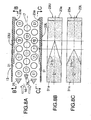
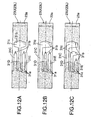
- FIGS. 5A to 5C and 6A to 6C show a second embodiment and a third embodiment of the present invention, respectively.
- the angle V at the downstream end of a cooling air guide channel 31 of each of air guide plates 23U and 23L is changed to 50° from the 33° of the first embodiment.
- the angle V at the downstream end of a cooling air guide channel 31 of each of air guide plates 23U and 23L is changed to 90° from the 33° of the first embodiment.
- the cooling effect of the first embodiment was the highest, the cooling effect of the second embodiment was next, and the cooling effect of the third embodiment was the lowest.
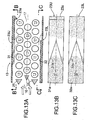
- FIGS. 7A, 7B, and 7C show a fourth embodiment of the present invention.
- Deep cooling air guide channels 31 are formed so as to have a depth of 11 mm in upper air guide plates 23U, and shallow ones are formed so as to have a depth of 5.5 mm in lower air guide plates 23L.
- the flow rate of the cooling air blowing down from the cooling air guide channels 31 of the upper air guide plates 23U is higher than the flow rate of the cooling air blowing up from the cooling air guide channels 31 of the lower air guide plates 23L, thereby preventing the flow of cooling air from becoming sluggish in the vicinity of the battery modules 11 in the middle tier, to enhance the cooling effect.
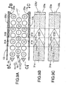
- FIGS. 8A, 8B, and 8C show a fifth embodiment of the present invention, in which the position of the downstream ends of cooling air guide channels 31 of lower air guide plates 23L are displaced, relative to the downstream ends of cooling air guide channels 31 of upper air guide plates 23U, to the upstream side by a distance corresponding to the pitch at which battery modules 11 are arranged in the front-to-rear direction. Since the positions of the upstream ends of tapered portions 31b of the upper and lower cooling air guide channels 31 are the same, an angle V of the lower cooling air guide channels 31 is larger than an angle V of the upper cooling air guide channels 31.
- the position at which the cooling air blows down from the cooling air guide channels 31 of the upper air guide plates 23U is displaced from the position at which the cooling air blows up from the cooling air guide channels 31 of the lower air guide plates 23L, thereby preventing the cooling air from the upper direction and the cooling air from the lower direction from counteracting each other in the vicinity of the battery modules 11 in the middle tier, to prevent the flow of cooling air from becoming sluggish, whereby the cooling effect to the battery modules 11 is enhanced.
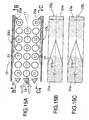
- FIGS. 9A, 9B, and 9C show a sixth embodiment of the present invention, in which the depth of cooling air guide channels 31A and 31B changes in two steps. That is, the cooling air guide channels 31A on the upstream side close to a cooling air inlet 16 are deep and have a V-shaped extremity of 50°, and the cooling air guide channels 31B extending from the rear of the cooling air guide channels 31A to the downstream side are shallow and similarly have a V-shaped extremity of 50°.
- the cooling air guide channels 31A and 31B are made so as to form a plurality of steps so that the depth becomes gradually shallower from the upstream side to the downstream side, it is possible to deflect the cooling air inward more smoothly, thereby further improving the cooling effect to the battery modules 11 in the middle tier.
- the downstream ends of the cooling air guide channels 31B are arranged on the downstream side directly in front of the battery module 11 that most requires the cooling, it is possible to effectively cool the battery module 11.
- FIGS. 10A, 10B, and 10C show a seventh embodiment of the present invention. Also in this seventh embodiment, the depth of cooling air guide channels 31A and 31B changes in two steps, but since the starting positions of the two cooling air guide channels 31A and 31B are the same, an angle V of a tapered portion 31b of the cooling air guide channels 31A on the upstream side is large, and an angle V of the cooling air guide channels 31B on the downstream side, which are formed only from the tapered portion 31b, is small.
- This seventh embodiment gives the same operational effect as that of the sixth embodiment.
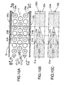
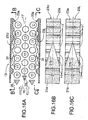
- FIGS. 11A, 11B, and 11C show an eighth embodiment of the present invention.
- each of air guide plates 23U and 23L has three cooling air guide channels 31C to 31E.
- the cooling air guide channel 31D which is in the middle in the left-and-right direction, extends most to the downstream side.
- a section where a positive electrode and a negative electrode are connected together easily generates heat because of contact resistance, but in accordance with this embodiment, since cooling air can be oriented to a desired position in the left-and-right direction (longitudinal direction) of the battery modules 11, it is possible to concentrate the cooling air on a high temperature section of the battery modules 11.
- FIGS. 12A, 12B, and 12C are modified examples of the eighth embodiment.
- a downstream section of one or two of the three cooling air guide channels 31C to 31E provided in each of the air guide plates 23U and 23L is first enlarged and then tapered into a V shape.
- a cooling air guide channel 31D in the middle has an enlarged portion 31c
- a cooling air guide channel 31C on one side has an enlarged portion 31c
- cooling air guide channels 31C and 31D on one side and in the middle have enlarged portions 31c.
- FIGS. 13A, 13B, and 13C show a ninth embodiment of the present invention.
- the upper and lower air guide plates 23U and 23L both have cooling air guide channels 31, and 31A to 31E, but in the ninth embodiment upper air guide plates 23U have cooling air guide channels 31, and lower air guide plates 23L have protruding portions 32.
- the protruding portions 32 have the same shape as that of the cooling air guide channels 31, and are formed from a parallel portion 32a and a tapered portion 32b. Furthermore, there is no projection 23a at the rear end of the lower air guide plates 23L.
- the upper air guide plates 23U deflect the flow of cooling air in the rear half of the battery case 13 by the effect of the cooling air guide channels 31, and this tendency is further promoted by the protruding portions 32 of the lower air guide plates 23L.
- the cooling air efficiently comes into contact with the battery modules 11 positioned in a rear part of the middle tier, for which contact with the cooling air is difficult.
- FIGS. 14A, 14B, 14C, 14D, and 14E show modified examples of the first embodiment.
- the tapered portion 31b of the cooling air guide channel 31 is made into a simple tapered shape, but in these modified examples the shapes of tapered portions 31b are different.
- a tapered portion 31b has a generally convex shape formed by combining a plurality of straight lines
- a tapered portion 31b has a generally convex shape formed by combining straight lines on the upstream side and a curved line on the downstream side
- a tapered portion 31b has a two-step tapered shape
- a tapered portion 31b has a generally concave shape formed by combining a plurality of straight lines
- one of the left and right sides of a tapered portion 31b is formed from one straight line and the other has a concave shape formed from a plurality of straight lines.
- the effect of the tapered portion 31b in deflecting the cooling air in the vertical direction is the highest for the modified example of FIG. 14A , and decreases in the order A ⁇ B ⁇ C ⁇ D ⁇ E.
- the cooling air can be oriented to any position in the longitudinal direction of the battery modules 11, thereby effectively cooling a high temperature section.
- FIGS. 15A, 15B, and 15C show another modified example of the first embodiment.
- the battery modules 11 are arranged in a staggered manner, but in this modified example battery modules 11 are arranged in a grid manner.
- This modified example can also attain the same operational effect as that of the first embodiment.
- FIGS. 16A, 16B, and 16C show a tenth embodiment of the present invention.
- each of air guide plates 23U and 23L is provided on an inner face thereof with semicylindrical projections 11', which function as dummy battery modules 11. These projections 11' are arranged in a staggered manner relative to the battery modules 11.
- By providing the projections 11' it is possible to make the state of the space between the inner face of each of the air guide plates 23U and 23L and the battery modules 11 the same as that of the space between the battery modules 11 in the upper, middle, and lower tiers.
- a cooling air guide channel 31 is formed from a parallel portion 31a and a tapered portion 31b by cutting off a portion of the projections 11'.
- the projections 11' arranged in the staggered manner relative to the battery modules 11 have the function of pushing the cooling air into spaces between the upper and lower tier battery modules 11 that are adjacent in the front-to-rear direction, the cooling effect to the battery modules 11 in the middle tier can be further improved, in combination with the function of the cooling air guide channels 31 of pushing in the cooling air.
- any combination of the aspects of the above embodiments is also an embodiment of the present invention.
- the depths of the cooling air guide channels 31A and 31B are changed in two steps, but they may be changed in three or more steps, or they may be continuously changed.
- a battery case housing a large number of battery modules is formed into the shape of a rectangular tube having a cooling air inlet and a cooling air outlet, and V-shaped cooling air guide channels having a decreasing flow-path cross sectional area are provided on inner faces of air guide plates that define upper and lower faces of the rectangular tube.
- the flow of cooling air is deflected by these V-shaped cooling air guide channels toward a central part on the downstream side, thus effectively cooling the battery modules disposed in the central part, for which the cooling effect is poor to make uniform the temperature of the battery modules, resulting in a suppressed variation in capacity and lifetime.
- it is not necessary to provide a bypass passage in the battery case it is possible to simplify the structure of the battery case, reduce the dimensions, and improve the degree of freedom in the layout.
Landscapes
- Chemical & Material Sciences (AREA)
- Chemical Kinetics & Catalysis (AREA)
- Electrochemistry (AREA)
- General Chemical & Material Sciences (AREA)
- Engineering & Computer Science (AREA)
- Manufacturing & Machinery (AREA)
- Secondary Cells (AREA)
- Battery Mounting, Suspending (AREA)
- Cooling, Air Intake And Gas Exhaust, And Fuel Tank Arrangements In Propulsion Units (AREA)
- Arrangement Or Mounting Of Propulsion Units For Vehicles (AREA)
Claims (11)
- Batteriekühlungsstruktur, worin eine Mehrzahl von stabförmigen Batteriemodulen (11), welche mit Kühlluft gekühlt werden, in vorbestimmten Intervallen innerhalb eines Batteriegehäuses (13) zueinander parallel angeordnet sind,
wobei das Batteriegehäuse (13) in der Gestalt eines rechteckigen Rohrs, das einen Kühllufteinlass (16) und einen Kühlluftauslass (17) aufweist, mittels eines einander gegenüberliegenden Paars von ersten Platten (14) und eines einander gegenüberliegenden Paars von zweiten Platten (15) gebildet ist, wobei entgegengesetzte Enden der großen Anzahl von Batteriemodulen (11) an dem Paar von ersten Platten angebracht sind, dadurch gekennzeichnet, dass eine Luftleitplatte (23U, 23L) an einer Innenseite von zumindest einer des Paars von zweiten Platten (15) befestigt ist und mit einem Kühlluftleitkanal (31) versehen ist, der aus einem parallelen Abschnitt (31 a) fester Breite, der an der Seite des Kühllufteinlasses (16) angeordnet ist, und einem verjüngten Abschnitt (31 b), der an der Seite des Kühlluftauslasses (17) angeordnet ist und dessen Strömungswegquerschnittsfläche von der Seite des Kühllufteinlasses (16) zur Seite des Kühlluftauslasses (17) hin abnimmt, gebildet ist. - Die Batteriekühlungsstruktur nach Anspruch 1, worin der Kühlluftleitkanal (31) einen im Wesentlichen V-förmig verjüngten Abschnitt (32b) aufweist, dessen Kanalbreite von der stromaufwärtigen Seite zur stromabwärtigen Seite des Kühlluftstroms abnimmt.
- Die Batteriekühlungsstruktur nach Anspruch 1 oder 2, worin die Tiefe des Kühlluftleitkanals (31) zwischen der einen zweiten Platte und der anderen zweiten Platte unterschiedlich ist.
- Die Batteriekühlungsstruktur nach Anspruch 1 oder 2, worin die Position des in Richtung des Kühlluftstroms stromabwärtigen Endes des Kühlluftleitkanals (31) zwischen der einen zweiten Platte und der anderen zweiten Platte unterschiedlich ist.
- Die Batteriekühlungsstruktur nach Anspruch 1 oder 2, worin, je weiter zur stromabwärtigen Seite des Kühlluftstroms, desto geringer die Tiefe des Kühlluftleitkanals (31) von zumindest einer der zweiten Platten ist.
- Die Batteriekühlungsstruktur nach Anspruch 1 oder 2, worin eine der zweiten Platten mit dem Kühlluftleitkanal (31) versehen ist und die andere zweite Platte mit einem Vorsprungsabschnitt (32) versehen ist, der zum Kühlluftleitkanal weist.
- Die Batteriekühlungsstruktur nach Anspruch 1 oder 2, worin zumindest eine der zweiten Platten eine Mehrzahl von Kühlluftleitkanälen aufweist, die in Richtung orthogonal zur Strömungsrichtung der Kühlluft nebeneinander angeordnet sind.
- Die Batteriekühlungsstruktur nach Anspruch 7, worin das Batteriemodul eine Mehrzahl von Batterieelementen enthält die in Serie miteinander verbunden sind, und die in der Richtung des Kühlluftstromes stromabwärtigen Enden der Mehrzahl von Kühlluftleitkanälen (31) zu einem Abschnitt hin orientiert sind, in dem die Batterieelemente verbunden sind.
- Die Batteriekühlungsstruktur nach Anspruch 2, worin der Kühlluftleitkanal an der in Richtung des Kühlluftstroms stromaufwärtigen Seite des verjüngten Abschnitts (32b) einen erweiterten Abschnitt aufweist, wobei der erweiterte Abschnitt eine vergrößerte Kanalbreite hat.
- Die Batteriekühlungsstruktur nach Anspruch 1 oder 2, worin an einer Innenseite von zumindest einer des Paars von zweiten Platten (15) ein Vorsprungsabschnitt ausgebildet ist, der die Form und die Anordnung der Batteriemodule simuliert.
- Die Batteriekühlungsstruktur nach einem der Ansprüche 1 bis 10, worin in dem Kühllufteinlass (16) des Batteriegehäuses (13) ein Strömungsregulierungselement (25) zum Unterdrücken des Kontakts von Kühlluft mit den Batteriemodulen (11) in der vordersten Reihe vorgesehen ist.
Applications Claiming Priority (2)
| Application Number | Priority Date | Filing Date | Title |
|---|---|---|---|
| JP2003426515A JP4485187B2 (ja) | 2003-12-24 | 2003-12-24 | バッテリケース |
| JP2003426515 | 2003-12-24 |
Publications (4)
| Publication Number | Publication Date |
|---|---|
| EP1548858A2 EP1548858A2 (de) | 2005-06-29 |
| EP1548858A3 EP1548858A3 (de) | 2009-03-04 |
| EP1548858B1 true EP1548858B1 (de) | 2011-06-08 |
| EP1548858B8 EP1548858B8 (de) | 2012-02-15 |
Family
ID=34544958
Family Applications (1)
| Application Number | Title | Priority Date | Filing Date |
|---|---|---|---|
| EP20040029576 Expired - Lifetime EP1548858B8 (de) | 2003-12-24 | 2004-12-14 | Batteriekühlungsstruktur |
Country Status (4)
| Country | Link |
|---|---|
| US (1) | US7399551B2 (de) |
| EP (1) | EP1548858B8 (de) |
| JP (1) | JP4485187B2 (de) |
| CN (1) | CN1320694C (de) |
Cited By (1)
| Publication number | Priority date | Publication date | Assignee | Title |
|---|---|---|---|---|
| CN110061323A (zh) * | 2019-03-29 | 2019-07-26 | 华为技术有限公司 | 一种热管理装置、热管理系统及新能源汽车 |
Families Citing this family (75)
| Publication number | Priority date | Publication date | Assignee | Title |
|---|---|---|---|---|
| JP4749774B2 (ja) * | 2005-06-16 | 2011-08-17 | 本田技研工業株式会社 | 組電池 |
| WO2006135008A1 (ja) * | 2005-06-17 | 2006-12-21 | Nec Lamilion Energy, Ltd. | 電気デバイス集合体およびフィルム外装電気デバイス構造体 |
| KR100684769B1 (ko) * | 2005-07-29 | 2007-02-20 | 삼성에스디아이 주식회사 | 이차 전지 모듈 |
| JP4659699B2 (ja) | 2005-07-29 | 2011-03-30 | 三星エスディアイ株式会社 | 電池モジュール |
| KR100684770B1 (ko) * | 2005-07-29 | 2007-02-20 | 삼성에스디아이 주식회사 | 이차 전지 모듈 |
| KR100937903B1 (ko) * | 2005-11-03 | 2010-01-21 | 주식회사 엘지화학 | 전지팩의 밀폐형 열교환 시스템 |
| US20080076016A1 (en) * | 2006-09-21 | 2008-03-27 | Debashis Ghosh | Design for reducing thermal spreads within a battery module |
| KR100837972B1 (ko) * | 2006-11-28 | 2008-06-13 | 현대자동차주식회사 | 배터리모듈의 냉각 또는 가열장치의 구조 |
| KR100862436B1 (ko) | 2006-11-29 | 2008-10-08 | 현대자동차주식회사 | 배터리 모듈 냉각용 지지장치 |
| KR100938626B1 (ko) * | 2006-12-30 | 2010-01-22 | 주식회사 엘지화학 | 냉매 유량의 분배 균일성이 향상된 중대형 전지팩 케이스 |
| CN101682007A (zh) * | 2007-03-01 | 2010-03-24 | 江森自控帅福得先进能源动力系统有限责任公司 | 电池模块 |
| KR100981878B1 (ko) * | 2007-06-14 | 2010-09-14 | 주식회사 엘지화학 | 냉매 유량의 분배 균일성이 향상된 중대형 전지팩 케이스 |
| JP4479753B2 (ja) * | 2007-06-20 | 2010-06-09 | トヨタ自動車株式会社 | 蓄電装置 |
| US8114535B2 (en) * | 2007-06-21 | 2012-02-14 | Delphi Technologies, Inc. | Metering schemes for reducing thermal spread in a battery pack |
| KR101029838B1 (ko) | 2007-06-28 | 2011-04-15 | 주식회사 엘지화학 | 냉각 효율이 향상된 중대형 전지팩 |
| FR2919119B1 (fr) | 2007-07-16 | 2009-12-04 | Valeo Equip Electr Moteur | Dispositif compact d'alimentation electrique comportant des moyens de refroidissement |
| JP5040566B2 (ja) * | 2007-09-28 | 2012-10-03 | 三菱自動車工業株式会社 | 電気自動車のバッテリー固定構造 |
| JP5092657B2 (ja) * | 2007-09-28 | 2012-12-05 | 三菱自動車工業株式会社 | バッテリユニット |
| JP4960839B2 (ja) * | 2007-11-12 | 2012-06-27 | 本田技研工業株式会社 | 車両用バッテリ冷却装置 |
| KR100974717B1 (ko) * | 2007-12-04 | 2010-08-06 | 현대자동차주식회사 | 연료전지차량용 cod 겸용 가열장치 |
| JP4787279B2 (ja) * | 2008-01-31 | 2011-10-05 | 三菱自動車工業株式会社 | 電池モジュールケース及び電池モジュールケースの使用方法 |
| JP5193660B2 (ja) * | 2008-04-03 | 2013-05-08 | 株式会社日立製作所 | 電池モジュール及びそれを備えた蓄電装置並びに電機システム |
| US7851080B2 (en) * | 2008-04-09 | 2010-12-14 | Gm Global Technology Operations, Inc. | Battery cooling plate design with discrete channels |
| KR101020587B1 (ko) * | 2008-06-12 | 2011-03-09 | 주식회사 엘지화학 | 냉매 유량의 분배 균일성이 향상된 중대형 전지팩 케이스 |
| FI123978B (fi) * | 2008-06-27 | 2014-01-15 | Planmeca Oy | Hammashoitolaitteisto |
| KR20100065779A (ko) * | 2008-12-08 | 2010-06-17 | 삼성전자주식회사 | 회전가능한 배터리 팩 |
| US20100157527A1 (en) * | 2008-12-23 | 2010-06-24 | Ise Corporation | High-Power Ultracapacitor Energy Storage Pack and Method of Use |
| WO2010111647A2 (en) * | 2009-03-27 | 2010-09-30 | Johnson Controls - Saft Advanced Power Solutions Llc | A battery module having a sealed vent chamber |
| EP2634028B1 (de) * | 2009-03-30 | 2017-01-11 | MAHLE Behr GmbH & Co. KG | Vorrichtung zur thermischen anbindung eines energiespeichers |
| CN102356506B (zh) * | 2009-04-28 | 2015-08-26 | 株式会社日立制作所 | 蓄电模块和具备它的蓄电装置 |
| JP5436924B2 (ja) * | 2009-05-08 | 2014-03-05 | 三洋電機株式会社 | バッテリシステム |
| JP5531626B2 (ja) | 2009-05-26 | 2014-06-25 | 日産自動車株式会社 | 車両のバッテリアセンブリ冷却構造、および、ウォータージャケット付きバッテリアセンブリ |
| US8268472B2 (en) | 2009-09-30 | 2012-09-18 | Bright Automotive, Inc. | Battery cooling apparatus for electric vehicle |
| US8647766B2 (en) * | 2010-06-22 | 2014-02-11 | Ford Global Technologies, Llc | Voltage detection in a battery |
| US8394525B2 (en) * | 2010-06-22 | 2013-03-12 | Ford Global Technologies, Llc | Support assembly for an array of battery cells |
| KR101264623B1 (ko) | 2010-09-28 | 2013-05-24 | 한라비스테온공조 주식회사 | 차량용 배터리 냉각장치 |
| US9905821B2 (en) | 2010-11-15 | 2018-02-27 | Volkswagen Ag | Vehicle battery packaging |
| US8679662B2 (en) | 2011-01-04 | 2014-03-25 | Ford Global Technologies, Llc | Battery assembly with gas discharge mechanism |
| CN102714283B (zh) * | 2011-01-24 | 2015-03-11 | 冯国安 | 动力电池包冷却装置 |
| JP6045198B2 (ja) * | 2011-06-08 | 2016-12-14 | 株式会社Gsユアサ | 電池パック |
| US8722223B2 (en) * | 2011-09-01 | 2014-05-13 | Samsung Sdi Co., Ltd. | Battery pack |
| CN103987607B (zh) * | 2011-12-09 | 2016-08-24 | 三菱电机株式会社 | 车辆用地板下装置的冷却装置 |
| JP5762942B2 (ja) * | 2011-12-26 | 2015-08-12 | タイガースポリマー株式会社 | 電池冷却構造 |
| JP5766596B2 (ja) * | 2011-12-26 | 2015-08-19 | タイガースポリマー株式会社 | 電池冷却構造 |
| JP5744714B2 (ja) * | 2011-12-26 | 2015-07-08 | タイガースポリマー株式会社 | 電池冷却構造 |
| DE102012007317B4 (de) | 2012-04-12 | 2026-05-07 | Volkswagen Aktiengesellschaft | Vorrichtung zur Befestigung zumindest eines Batteriemoduls in einem Batteriekasten einer Traktionsbatterie |
| US10744901B2 (en) | 2012-06-13 | 2020-08-18 | Ford Global Technologies, Llc | Cooling system having active cabin venting for a vehicle battery |
| DE102012012891A1 (de) | 2012-06-28 | 2014-01-02 | Volkswagen Aktiengesellschaft | Vorrichtung zur Verbindung von Batteriemodulen |
| DE102012014775A1 (de) | 2012-07-25 | 2014-01-30 | Volkswagen Aktiengesellschaft | Vorrichtung zur Anordnung von Batteriemodulen in einer Fahrzeugbatterie |
| KR101669118B1 (ko) * | 2013-01-03 | 2016-10-25 | 삼성에스디아이 주식회사 | 배터리 팩 |
| US10062934B2 (en) * | 2013-07-25 | 2018-08-28 | Johnson Controls Technology Company | Cooling system and method for lithium-ion battery module |
| US9067486B2 (en) * | 2013-08-30 | 2015-06-30 | Ford Global Technologies, Llc | Air cooling system for high voltage battery cell arrays |
| US11569537B2 (en) | 2014-03-25 | 2023-01-31 | Teledyne Scientific & Imaging, Llc | Multi-functional structure for thermal management and prevention of failure propagation |
| US11769919B2 (en) | 2014-03-25 | 2023-09-26 | Teledyne Scientific & Imaging, Llc | Multi-functional high temperature structure for thermal management and prevention of explosion propagation |
| US11482744B2 (en) | 2014-03-25 | 2022-10-25 | Teledyne Scientific & Imaging, Llc | Multi-functional structure for thermal management and prevention of failure propagation |
| KR101664652B1 (ko) | 2015-01-29 | 2016-10-10 | 현대자동차주식회사 | 하이브리드 차량의 배터리 냉각시스템, 그 작동방법 및 그 제어방법 |
| KR101822304B1 (ko) * | 2016-10-24 | 2018-01-25 | 현대자동차주식회사 | 배터리 냉각장치 |
| US10594004B2 (en) * | 2016-12-12 | 2020-03-17 | Lg Chem, Ltd. | Battery pack |
| KR101965373B1 (ko) * | 2017-01-06 | 2019-04-03 | 주식회사 엘지화학 | 원통형 배터리 모듈 |
| US10950834B2 (en) | 2017-03-02 | 2021-03-16 | Purdue Research Foundation | Crushable cooling column for battery assembly in electric vehicle |
| JP7212636B2 (ja) * | 2018-01-31 | 2023-01-25 | 三洋電機株式会社 | 電池パック |
| KR102185528B1 (ko) * | 2018-11-26 | 2020-12-02 | 주식회사 코리아하이텍 | 배터리 일체형 저전압 디씨-디씨 컨버터 |
| JP7136015B2 (ja) * | 2019-06-17 | 2022-09-13 | 日本電気硝子株式会社 | ガラス移送装置 |
| JP7224245B2 (ja) * | 2019-06-24 | 2023-02-17 | 株式会社クボタ | 電動作業車 |
| JP7016844B2 (ja) * | 2019-09-03 | 2022-02-07 | 本田技研工業株式会社 | バッテリパック |
| US11949116B2 (en) * | 2019-10-30 | 2024-04-02 | Baidu Usa Llc | High power and energy density battery backup unit cell package design |
| CN112103594B (zh) * | 2020-09-27 | 2024-12-17 | 清华大学苏州汽车研究院(吴江) | 一种浸没式液冷电池包 |
| DE102020007429A1 (de) * | 2020-12-07 | 2022-06-09 | Mercedes-Benz Group AG | Temperiervorrichtung zum Temperieren eines Zellblocks, eines elektrischen Energiespeichers sowie Verfahren |
| CN113571339B (zh) * | 2021-07-09 | 2022-07-22 | 武汉理工大学 | 一种电动汽车用超级电容器封装结构 |
| DE102021209351A1 (de) | 2021-08-25 | 2023-03-02 | Fronius International Gmbh | Energiespeichervorrichtung für ein Schweißgerät |
| CN114039124A (zh) * | 2021-11-09 | 2022-02-11 | 镇江市高等专科学校 | 一种基于磁制冷效应的动力电池多级散热系统及控制方法 |
| JP7473575B2 (ja) * | 2022-03-18 | 2024-04-23 | 本田技研工業株式会社 | バッテリカバー、およびバッテリカバー組立体 |
| DE102022212735A1 (de) | 2022-11-28 | 2024-05-29 | Fronius International Gmbh | Regelungsschaltung zur Regelung einer Energiespeichervorrichtung |
| DE102022212738B4 (de) | 2022-11-28 | 2024-08-22 | Fronius International Gmbh | Energiespeichervorrichtung mit Temperaturanpassung |
| DE102022212736A1 (de) | 2022-11-28 | 2024-05-29 | Fronius International Gmbh | Energiespeichervorrichtung mit Aufnahmekäfig für Energiespeicherzellen |
Family Cites Families (13)
| Publication number | Priority date | Publication date | Assignee | Title |
|---|---|---|---|---|
| DE3900381C1 (de) * | 1989-01-09 | 1990-09-27 | Licentia Patent-Verwaltungs-Gmbh, 6000 Frankfurt, De | |
| US5015545A (en) * | 1990-01-03 | 1991-05-14 | General Motors Corporation | Method and apparatus for cooling an array of rechargeable batteries |
| US5585204A (en) * | 1993-12-27 | 1996-12-17 | Honda Giken Kogyo Kabushiki Kaisha | Temperature control structure for batteries and battery box for housing such batteries |
| JP3450908B2 (ja) | 1994-09-21 | 2003-09-29 | 本田技研工業株式会社 | バッテリ冷却用ファン構造体 |
| JP3829391B2 (ja) | 1997-03-07 | 2006-10-04 | トヨタ自動車株式会社 | 電池アセンブリ及び電動車両 |
| JP3861359B2 (ja) * | 1997-03-12 | 2006-12-20 | トヨタ自動車株式会社 | 電池温度調整装置 |
| JPH11329518A (ja) * | 1998-05-21 | 1999-11-30 | Toshiba Battery Co Ltd | 電池装置 |
| US6255015B1 (en) * | 1998-08-23 | 2001-07-03 | Ovonic Battery Company, Inc. | Monoblock battery assembly |
| JP2000133225A (ja) * | 1998-10-30 | 2000-05-12 | Sanyo Electric Co Ltd | 組電池 |
| JP4665289B2 (ja) * | 2000-05-12 | 2011-04-06 | 株式会社Gsユアサ | 組電池 |
| JP4233733B2 (ja) * | 2000-07-17 | 2009-03-04 | パナソニック株式会社 | 電源装置及びその製造方法 |
| US6569556B2 (en) * | 2001-01-29 | 2003-05-27 | General Motors Corporation | Cooling system for a battery pack |
| US6677728B2 (en) * | 2002-04-12 | 2004-01-13 | Honda Giken Kogyo Kabushiki Kaisha | Battery box and battery holder having detachable ring-shaped members |
-
2003
- 2003-12-24 JP JP2003426515A patent/JP4485187B2/ja not_active Expired - Fee Related
-
2004
- 2004-12-14 EP EP20040029576 patent/EP1548858B8/de not_active Expired - Lifetime
- 2004-12-17 US US11/014,204 patent/US7399551B2/en not_active Expired - Fee Related
- 2004-12-24 CN CNB2004100816815A patent/CN1320694C/zh not_active Expired - Fee Related
Cited By (1)
| Publication number | Priority date | Publication date | Assignee | Title |
|---|---|---|---|---|
| CN110061323A (zh) * | 2019-03-29 | 2019-07-26 | 华为技术有限公司 | 一种热管理装置、热管理系统及新能源汽车 |
Also Published As
| Publication number | Publication date |
|---|---|
| EP1548858A3 (de) | 2009-03-04 |
| US7399551B2 (en) | 2008-07-15 |
| EP1548858A2 (de) | 2005-06-29 |
| JP4485187B2 (ja) | 2010-06-16 |
| CN1638185A (zh) | 2005-07-13 |
| JP2005183343A (ja) | 2005-07-07 |
| EP1548858B8 (de) | 2012-02-15 |
| US20050153199A1 (en) | 2005-07-14 |
| CN1320694C (zh) | 2007-06-06 |
Similar Documents
| Publication | Publication Date | Title |
|---|---|---|
| EP1548858B1 (de) | Batteriekühlungsstruktur | |
| US10944139B2 (en) | Air cooling battery module having guide vane | |
| KR100684768B1 (ko) | 이차 전지 모듈 | |
| US8802274B2 (en) | Secondary battery module and secondary battery module apparatus | |
| JP5293973B2 (ja) | 車両用バッテリ冷却構造 | |
| JP5606936B2 (ja) | 電池冷却構造 | |
| JP2010186681A (ja) | 組電池 | |
| JP2006073461A (ja) | 組電池 | |
| CN108258362A (zh) | 一种电池组冷却装置 | |
| JP5096842B2 (ja) | 電池格納ユニット | |
| KR20260010443A (ko) | 배터리 팩용 냉각 플레이트, 배터리 팩 및 전기 디바이스 | |
| JP2007227030A (ja) | 電池パック | |
| JP4498659B2 (ja) | バッテリーボックス | |
| JPH08241702A (ja) | バッテリ収納装置 | |
| US12362418B2 (en) | Vehicular battery case | |
| JP2012221802A (ja) | 組電池の冷却構造 | |
| EP4159514B1 (de) | Lufteinlasskanal | |
| KR20010036652A (ko) | 전기자동차의 배터리 냉각장치 | |
| JP7413676B2 (ja) | 空気流通装置 | |
| JP2007172982A (ja) | 電池パック | |
| KR20230089811A (ko) | 배터리 팩 | |
| JP4083632B2 (ja) | バッテリー式電源装置 | |
| US20250372763A1 (en) | Duct structure for an air-cooled battery | |
| JP7817673B2 (ja) | 車両用のバッテリーケース | |
| US20250372764A1 (en) | Outlet Duct System for Vehicle Air-Cooled Battery |
Legal Events
| Date | Code | Title | Description |
|---|---|---|---|
| PUAI | Public reference made under article 153(3) epc to a published international application that has entered the european phase |
Free format text: ORIGINAL CODE: 0009012 |
|
| AK | Designated contracting states |
Kind code of ref document: A2 Designated state(s): AT BE BG CH CY CZ DE DK EE ES FI FR GB GR HU IE IS IT LI LT LU MC NL PL PT RO SE SI SK TR |
|
| AX | Request for extension of the european patent |
Extension state: AL BA HR LV MK YU |
|
| PUAL | Search report despatched |
Free format text: ORIGINAL CODE: 0009013 |
|
| AK | Designated contracting states |
Kind code of ref document: A3 Designated state(s): AT BE BG CH CY CZ DE DK EE ES FI FR GB GR HU IE IS IT LI LT LU MC NL PL PT RO SE SI SK TR |
|
| AX | Request for extension of the european patent |
Extension state: AL BA HR LV MK YU |
|
| 17P | Request for examination filed |
Effective date: 20090417 |
|
| AKX | Designation fees paid |
Designated state(s): DE FR GB |
|
| 17Q | First examination report despatched |
Effective date: 20091019 |
|
| GRAP | Despatch of communication of intention to grant a patent |
Free format text: ORIGINAL CODE: EPIDOSNIGR1 |
|
| RIN1 | Information on inventor provided before grant (corrected) |
Inventor name: NISHIBORI, TAKEOC/O KABUSHIKI KAISHA HONDA Inventor name: TAKEDOMI, HARUMIC/O KABUSHIKI KAISHA HONDA Inventor name: KOIKE, EIJIC/O KABUSHIKI KAISHA HONDA Inventor name: YAGI, KAZUHIKOC/O KABUSHIKI KAISHA HONDA |
|
| GRAS | Grant fee paid |
Free format text: ORIGINAL CODE: EPIDOSNIGR3 |
|
| GRAA | (expected) grant |
Free format text: ORIGINAL CODE: 0009210 |
|
| RAP1 | Party data changed (applicant data changed or rights of an application transferred) |
Owner name: HONDA MOTOR CO., LTD. |
|
| AK | Designated contracting states |
Kind code of ref document: B1 Designated state(s): DE FR GB |
|
| REG | Reference to a national code |
Ref country code: GB Ref legal event code: FG4D |
|
| REG | Reference to a national code |
Ref country code: DE Ref legal event code: R096 Ref document number: 602004032952 Country of ref document: DE Effective date: 20110721 |
|
| RIN2 | Information on inventor provided after grant (corrected) |
Inventor name: NISHIBORI, TAKEOC/O KABUSHIKI KAISHA HONDA GIJUTSU Inventor name: TAKEDOMI, HARUMIC/O KABUSHIKI KAISHA HONDA GIJUTSU Inventor name: KOIKE, EIJIC/O KABUSHIKI KAISHA HONDA GIJUTSU KENK Inventor name: YAGI, KAZUHIKOC/O KABUSHIKI KAISHA HONDA GIJUTSU K |
|
| PGFP | Annual fee paid to national office [announced via postgrant information from national office to epo] |
Ref country code: FR Payment date: 20111219 Year of fee payment: 8 |
|
| PLBE | No opposition filed within time limit |
Free format text: ORIGINAL CODE: 0009261 |
|
| STAA | Information on the status of an ep patent application or granted ep patent |
Free format text: STATUS: NO OPPOSITION FILED WITHIN TIME LIMIT |
|
| 26N | No opposition filed |
Effective date: 20120309 |
|
| REG | Reference to a national code |
Ref country code: DE Ref legal event code: R097 Ref document number: 602004032952 Country of ref document: DE Effective date: 20120309 |
|
| GBPC | Gb: european patent ceased through non-payment of renewal fee |
Effective date: 20111214 |
|
| PG25 | Lapsed in a contracting state [announced via postgrant information from national office to epo] |
Ref country code: GB Free format text: LAPSE BECAUSE OF NON-PAYMENT OF DUE FEES Effective date: 20111214 |
|
| REG | Reference to a national code |
Ref country code: FR Ref legal event code: ST Effective date: 20130830 |
|
| PG25 | Lapsed in a contracting state [announced via postgrant information from national office to epo] |
Ref country code: DE Free format text: LAPSE BECAUSE OF NON-PAYMENT OF DUE FEES Effective date: 20130702 |
|
| REG | Reference to a national code |
Ref country code: DE Ref legal event code: R119 Ref document number: 602004032952 Country of ref document: DE Effective date: 20130702 |
|
| PG25 | Lapsed in a contracting state [announced via postgrant information from national office to epo] |
Ref country code: FR Free format text: LAPSE BECAUSE OF NON-PAYMENT OF DUE FEES Effective date: 20130102 |