EP1548482B1 - Objectif pour un microscope avec des montures correctives axialement ajustables - Google Patents
Objectif pour un microscope avec des montures correctives axialement ajustables Download PDFInfo
- Publication number
- EP1548482B1 EP1548482B1 EP04029779A EP04029779A EP1548482B1 EP 1548482 B1 EP1548482 B1 EP 1548482B1 EP 04029779 A EP04029779 A EP 04029779A EP 04029779 A EP04029779 A EP 04029779A EP 1548482 B1 EP1548482 B1 EP 1548482B1
- Authority
- EP
- European Patent Office
- Prior art keywords
- microscope objective
- rings
- ring
- corrective
- objective according
- Prior art date
- Legal status (The legal status is an assumption and is not a legal conclusion. Google has not performed a legal analysis and makes no representation as to the accuracy of the status listed.)
- Expired - Lifetime
Links
- 230000003287 optical effect Effects 0.000 claims abstract description 38
- 238000003384 imaging method Methods 0.000 claims description 3
- 230000002093 peripheral effect Effects 0.000 claims description 3
- 238000012937 correction Methods 0.000 description 39
- 238000006073 displacement reaction Methods 0.000 description 9
- 239000006059 cover glass Substances 0.000 description 4
- 238000007654 immersion Methods 0.000 description 3
- PEDCQBHIVMGVHV-UHFFFAOYSA-N Glycerine Chemical compound OCC(O)CO PEDCQBHIVMGVHV-UHFFFAOYSA-N 0.000 description 2
- 230000006978 adaptation Effects 0.000 description 2
- 230000006835 compression Effects 0.000 description 2
- 238000007906 compression Methods 0.000 description 2
- 238000005553 drilling Methods 0.000 description 2
- 230000007613 environmental effect Effects 0.000 description 2
- 238000000386 microscopy Methods 0.000 description 2
- 230000004075 alteration Effects 0.000 description 1
- 230000005540 biological transmission Effects 0.000 description 1
- 150000001875 compounds Chemical class 0.000 description 1
- 230000001419 dependent effect Effects 0.000 description 1
- 235000011187 glycerol Nutrition 0.000 description 1
- 230000003993 interaction Effects 0.000 description 1
- 239000007788 liquid Substances 0.000 description 1
- 238000010859 live-cell imaging Methods 0.000 description 1
- 238000004519 manufacturing process Methods 0.000 description 1
- 238000003801 milling Methods 0.000 description 1
- 230000008092 positive effect Effects 0.000 description 1
- 238000002360 preparation method Methods 0.000 description 1
- 210000002023 somite Anatomy 0.000 description 1
- XLYOFNOQVPJJNP-UHFFFAOYSA-N water Substances O XLYOFNOQVPJJNP-UHFFFAOYSA-N 0.000 description 1
Images


Classifications
-
- G—PHYSICS
- G02—OPTICS
- G02B—OPTICAL ELEMENTS, SYSTEMS OR APPARATUS
- G02B7/00—Mountings, adjusting means, or light-tight connections, for optical elements
- G02B7/02—Mountings, adjusting means, or light-tight connections, for optical elements for lenses
- G02B7/023—Mountings, adjusting means, or light-tight connections, for optical elements for lenses permitting adjustment
-
- G—PHYSICS
- G02—OPTICS
- G02B—OPTICAL ELEMENTS, SYSTEMS OR APPARATUS
- G02B21/00—Microscopes
- G02B21/02—Objectives
Definitions
- the invention relates to a microscope objective with axially adjustable correction frames, in which lenses or lens groups are arranged, in particular for live cell imaging and for research on cell and tissue cultures.
- the invention is applicable to microscope objectives in conjunction with different coverslips and / or different immersion liquids and / or at different operating temperatures.
- US 3,549,230 describes a similar lens system in which the axial positioning of actuators is made via a collar.
- grooves are made in the adjusting ring, engage in the pins (bolts).
- the actuators follow the pins (bolts) the grooves in the adjusting ring and thereby rotate the lens groups simultaneously.
- a major disadvantage is that the relatively complicated structure leads to inaccuracies in the optical transmission.
- a microscope objective with an aperture of at least 0.5 and a device for adjustment to different cover glass thicknesses in which a second lens group is arranged linearly displaceable between a fixed first lens group and a fixed third lens group, to which another lens group displaced axially in opposite directions can be.
- the movement strokes of these displaceable lens groups can be different.
- a single actuating ring is provided.
- the device for adjusting to different cover glass thicknesses is coupled with a device for refocusing the entire lens.
- the lens groups are linearly displaced during the adjustment movement. This can be achieved for example by threads of different pitch or by cams, which engage in corresponding grooves with constant, but different pitch in a rotatable intermediate ring of the lens barrel.
- a microscope objective with at least one correction mount is known, wherein the correction mount is axially displaceable and rotatable about the optical axis of the objective.
- a movable on a cam groove of a socket carrier pin is provided which is fixedly connected at one end to the correction socket and engages the other end in a rotatable ring.
- two axially displaceable and simultaneously rotatable correction frames are provided.
- An adjusting device for a lens is in the DE 199 47 378 A1 described, which is provided with an axially movable optical member which is connected via a sliding mount with the main frame.
- a first linear drive via actuators with a second linear drive, which generates the linear movement along the optical axis, connected.
- the second linear actuator is connected to the sliding mount.
- the invention is based on the object to provide a microscope objective with correction versions, with which with good correction of the aberrations and adherence to a small length of the lens setting for the purpose of compensation of at least three, the imaging quality influencing parameters is possible.
- an advantageous embodiment results in a small overall length of the entire lens when a main frame, which is firmly connected to an inner cylinder sleeve with axially directed openings; axially adjustable correction sockets for receiving optical members in the form of lenses and / or lens groups, wherein the correction frames are mounted in the cylinder sleeve and on each of which a respective, directed by an associated opening of the cylinder sleeve cross, radially directed bolt or screw is arranged; each with a bolt operatively connected, provided with an external thread of the same or different pitch threaded rings, which are mounted only axially displaceable on the cylinder sleeve and engage in an internal thread corresponding pitch of each of the threaded rings associated driving rings, which are rotatable about the optical axis in the main version are arranged and arranged with at least one outside of the main frame Adjusting ring are in operative connection and can be rotated with this.
- the bolts engage in a play formed by at least one resilient web, to the edge of each associated threaded ring hole open.
- the diameter of the bore is advantageously smaller than or equal to the diameter of the engaging in the bore of the threaded ring part of the respective bolt.
- a play-free connection between the bolt and the associated threaded ring also results advantageous when an elastic intermediate member is provided between the bolt and the wall of the bore of the threaded ring.
- An advantageous arrangement with many adjustment options for the optical members is obtained when a plurality of adjusting rings are provided, which are each operatively connected to at least one driving ring, wherein advantageously the individual adjusting rings can be rotated independently of each other about the optical axis of the lens.
- the driving rings associated with a driving ring have the same or different pitch thread.
- different correction conditions in the lens can be taken into account.
- spring elements are arranged to eliminate the backlash or the dead gear in the thread between the driving rings and the associated threaded rings.
- compression springs or elements which can exert the function of a compression spring can be used here.
- a security element serving to protect the object is connected to the front correction mount and axially movable together with the latter.
- an axially directed pin is provided at a located in the interior of the adjusting end face, that in a, located in the interior of the lens further end face of the main frame extending over a peripheral region Outbreak is provided, the boundary surfaces form stops for the pin, and that the adjustment ring on its outer surface a mark and the main frame have a scale with setting marks.
- the invention serves to use in a microscope objective an optical correction by axial displacement of three or more optical members by means of radially moving threaded rings with threads of the same or different pitch, so without the usual curve rings and without spiral grooves in individual rings realize.
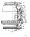
- This in Fig.1 in a partial section shown microscope objective comprises a provided with a screw thread 1.1 main version 1 with a firmly connected to this, inner cylinder sleeve 2, which has axially directed openings 3.1 to 3.4 and are arranged in the precise, axially adjustable correction frames 4.1 to 4.4.
- four correction frames 4.1 to 4.4 are provided.
- the cylinder sleeve 2 also has a corresponding number of openings. The number of components working together with the correction sockets also depends on the number of correction sockets.
- the individual optical members (not shown) are fixed, which consist of individual lenses and / or lens groups.
- the individual correction sockets 4.1 to 4.4 is outside each one, by an associated breakthrough 3.1 to 3.4 of the cylinder sleeve 2 through reaching (gripping) radially directed bolt 6.1 to 6.4 or a screw arranged.
- Each of these bolts 6.1 to 6.4 is in operative connection with a threaded ring 9.1 to 9.4 assigned to it.
- These threaded rings 9.1 to 9.4 each have an external thread 8.1 to 8.4 and are mounted only axially adjustable on the cylinder sleeve 2.
- the threaded rings 9.1 to 9.4 and the driving rings 10.1 to 10.4 can have threads of the same or different pitch, so that with the same rotation of the driving rings 10.1 to 10.4 about the optical axis 7 of the lens, the rotationally fixed threaded rings 9.1 to 9.4 different shifts in the direction of the optical axis To run.
- the individual driving rings 10.1 to 10.4 are advantageously connected by screws 13.1 to 13.3 or pins together and communicate with at least one, from the outside to be actuated and rotatable about the optical axis 7 adjusting ring 11 in operative connection.
- an adjustment ring 11 is provided, with which the driving rings 10.1 to 10.4 can be adjusted simultaneously and together by the same rotations.
- a lens (not shown), which has a plurality of adjusting rings, in which case one or more driving rings are associated with an adjusting ring, with which different axial Displacements of the correction frames can be performed with the optical members included therein.
- the objective On the object side, the objective has a securing element 14 serving for object or specimen protection, which is connected via an intermediate part 14.1 to the front correction mount 4.1 and is moved axially together with the latter.
- spring elements 12.1 to 12.4 are provided, which are the thread flanks of the operatively connected thread of the respective threaded and driving rings always press against each other.
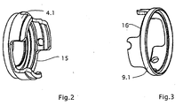
- the correction socket 4.1 of the front optical element ( Fig.2 ) and the associated first threaded ring 9.1 ( Figure 3 ) provided with recesses 15 and 16. This allows unhindered sliding of the threaded ring 9.1 and the correction frame 4.1 while simultaneously guiding the correction frame 4.1 and the threaded ring 9.1 precisely.
- lenses with a greater length can be dispensed with such interlocking, space-saving components.
- Fig. 4 and Fig. 5 show the example of the threaded ring 9.1 and the bolt 6.1 as a play-free connection according to the invention between these two components is realized. Particularly in the case of high-quality microscopic objectives, such a connection is absolutely necessary in order to achieve a virtually defect-free image.
- a compound engages the screwed in the correcting version 4.1 and radially directed bolt 6.1 in a free direction in the axial direction to the edge 19 of the threaded ring 9.1 bore 20 a.
- This bore 20 is through two, by cutouts 21 and 22 of the threaded ring 9.1 generated, resilient webs 17; 18 formed.
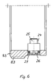
- Fig. 6 will be explained in more detail with reference to the threaded ring 9.3 and the bolt 6.3.
- the bolt 6.3 which with its, provided with thread 24 end 25 in the correction socket 4.3 (in Fig. 6 not shown), engages in a bore 26 of the associated, provided with the thread 8.3 threaded ring 9.3.
- the backlash ensuring intermediate member 27 is arranged between the bolt 6.3 and the wall of the bore 26 .
- this intermediate member 27 has the shape of a circular ring. Other suitable designs of the intermediate member 27 are also possible.
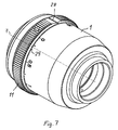
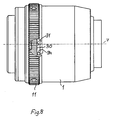
- spatially illustrated microscope objective includes, inter alia, the main frame 1 and the adjusting ring 11 rotatably mounted thereon, which has a marking 28.
- 1 Setting marks 29 are arranged, which can serve for example, the adaptation of the lens to different coverslips or to different environmental conditions.
- Fig. 7 and 8th 1 illustrates that an axially directed pin 31, preferably in a bore, is arranged on an end face 30 located in the interior of the adjusting ring 11.
- This pin 31 is arranged in a defined position for marking the adjusting ring 11.
- the main frame 1 has in its interior at an end face 32 ( Fig. 10 ) extending over a peripheral area outbreak 33, the boundary surfaces as stops 34; 35 serve for the pin 31 in the rotation of the adjusting ring 11 relative to the main frame 1.
- the limitation of the outbreak 33, so the attacks 34; 35 are also oriented to the mark 28 of the adjusting ring 11.
- the angle of the breakout 33 of the main frame 1 determines the width of the overflow, which advantageously allows passing the Nulleinstellmarke in both directions within narrow limits.
- the uniformity of the overflow is automatically given by the respective orientation of the outbreak 33 to the respective adjustment mark 29 of the main version 1.
- a uniform overflow and 7undfest stops 34; 35 to limit the rotation of the adjusting ring 11 achieved.
- This arrangement is applicable to all microscope objectives with one or more adjustment rings, such. B. also micro-lenses with iris diaphragm.
Landscapes
- Physics & Mathematics (AREA)
- General Physics & Mathematics (AREA)
- Optics & Photonics (AREA)
- Chemical & Material Sciences (AREA)
- Analytical Chemistry (AREA)
- Microscoopes, Condenser (AREA)
- Lens Barrels (AREA)
- Lenses (AREA)
Claims (12)
- Objectif de microscope avec des montures de correction axialement ajustables (4.1 à 4.4) pour l'adaptation à différents paramètres influençant la qualité de reproduction, dans lequel le réglage axial des montures de correction (4.1 à 4.4) par rapport à une monture principale fixe (1) est réalisable au moyen d'une bague de réglage (11) disposée à l'extérieur de la monture principale (1) par l'intermédiaire d'un goujon (6.1 à 6.4) disposé dans la monture de correction (4.1 à 4.4) respective, dirigé radialement par rapport à l'axe optique de l'objectif, engrenant dans des percées de bagues filetées (9.1 à 9.4), dans lequel l'objectif comporte au moins trois montures de correction (4.1 à 4.4) et les montures de correction (4.1 à 4.4) pouvant être réglées au moyen d'au moins une bague de réglage (11) sans rotation supplémentaire autour de l'axe optique (7) de l'objectif en direction de cet axe (7),
caractérisé en ce que les goujons (6.1 à 6.4) engrènent sans jeu dans un perçage (20) formé par au moins une traverse élastique (17, 18), ouverte sur le bord (19) de la bague filetée (9.1 à 9.4) respectivement correspondante. - Objectif de microscope selon la revendication 1, comportant
une monture principale (1) reliée solidement à une douille cylindrique (2) reposant à l'intérieur avec des percées (3.1 à 3.4) orientées radialement,
des montures de correction axialement ajustables (4.1 à 4.4) pour l'accueil d'éléments optiques reposant dans la douille cylindrique (2) de manière à pouvoir coulisser axialement et disposés à l'extérieur du goujon respectif dirigé radialement (6.1 à 6.4) ou de la vis, passant à travers une percée correspondante (3.1 à 3.4) de la douille cylindrique (2),
dans lesquelles des bagues filetées (9.1 à 9.4) reposant dans la douille cylindrique (2) de manière à ne pouvoir coulisser qu'axialement et avec un pas de vis correspondant au filetage interne des bagues d'entrainement (10.1 à 10.4) correspondant aux bagues filetées (9.1 à 9.4) respectives, engrènent avec un goujon respectif (6.1 à 6.4) en liaison active, avec un filetage externe (8.1 à 8.4) pourvu d'un pas de vis identique ou différent, les bagues d'entrainement (10.1 à 10.4) étant disposées dans la monture principale (1) de manière à pouvoir pivoter autour de l'axe optique (7) et en liaison active avec au moins une bague de réglage (11) disposée à l'extérieur de la monture principale (1) et pouvant pivoter avec celle-ci. - Objectif de microscope selon la revendication 2, caractérisé en ce que les bagues d'entrainement (10.1 à 10.4) en liaison active avec une bague de réglage (11) sont reliées solidement entre elles et peuvent pivoter ensemble au moyen de la bague de réglage (11) autour de l'axe optique (7).
- Objectif de microscope selon une des revendications 1 à 3, caractérisé en ce qu'on a prévu plusieurs bagues de réglage (11) en liaison active avec au moins une bague d'entrainement (10.1 à 10.4) respective.
- Objectif de microscope selon une des revendications 1 à 4, caractérisé en ce que les bagues d'entrainement (10.1 à 10.4) correspondant à une bague de réglage (11) comportent des filetages de pas de vis identique ou différent.
- Objectif de microscope selon une des revendications 1 à 5, caractérisé en ce qu'on dispose des éléments de ressorts (12.1 à 12.4) pour éliminer le jeu ou le point mort du filetage entre les bagues d'entrainement (10.1 à 10.4) et les bagues filetées (9.1 à 9.4) correspondantes.
- Objectif de microscope selon la revendication 6, caractérisé en ce que les éléments de ressorts (12.1 à 12.4) sont des ressorts de compression.
- Objectif de microscope selon une des revendications 1 à 7, caractérisé en ce qu'un élément de sécurité (14) servant à la protection de l'objet est relié à la monture de correction avant (4.1) et est axialement mobile ensemble avec la monture de correction (4.1).
- Objectif de microscope selon la revendication 1, caractérisé en ce que le diamètre du perçage (20) est inférieur ou égal au diamètre de la partie du goujon respectif (6.1 à 6.4) engrenant dans le perçage (20).
- Objectif de microscope selon la revendication 1, caractérisé en ce qu'on a prévu un élément intermédiaire élastique entre le goujon (6.1 à 6.4) et le perçage (20) correspondant de la bague filetée respective (9.1 à 9.4).
- Objectif de microscope selon une des revendications 1 à 8, caractérisé en ce qu'on a prévu une broche (31) dirigée axialement sur la surface frontale (30) située à l'intérieur de la bague de réglage (11),
en ce qu'on a prévu une encoche (33) s'étendant sur un domaine du périmètre d'une autre surface frontale (32) de la monture principale (1) située à l'intérieur de l'objectif, dont les surfaces de limitation forment des butées (34 ; 35) pour la broche (31),
et en ce que la bague de réglage (11) possède un marquage (28) et la monture principale (1) possède une échelle avec des graduations (29) sur au moins une partie de son périmètre. - Objectif de microscope selon la revendication 11, caractérisé en ce que les positions de la broche (31) dirigée axialement et les positions des butées (34 ; 35) sont orientées vers le marquage (28) de la bague de réglage (11).
Applications Claiming Priority (2)
| Application Number | Priority Date | Filing Date | Title |
|---|---|---|---|
| DE10361911A DE10361911A1 (de) | 2003-12-24 | 2003-12-24 | Mikroskopobjektiv mit axial verstellbaren Korrekturfassungen |
| DE10361911 | 2003-12-24 |
Publications (2)
| Publication Number | Publication Date |
|---|---|
| EP1548482A1 EP1548482A1 (fr) | 2005-06-29 |
| EP1548482B1 true EP1548482B1 (fr) | 2011-09-28 |
Family
ID=34530418
Family Applications (1)
| Application Number | Title | Priority Date | Filing Date |
|---|---|---|---|
| EP04029779A Expired - Lifetime EP1548482B1 (fr) | 2003-12-24 | 2004-12-16 | Objectif pour un microscope avec des montures correctives axialement ajustables |
Country Status (5)
| Country | Link |
|---|---|
| US (1) | US7259924B2 (fr) |
| EP (1) | EP1548482B1 (fr) |
| JP (1) | JP2005189856A (fr) |
| AT (1) | ATE526602T1 (fr) |
| DE (1) | DE10361911A1 (fr) |
Families Citing this family (7)
| Publication number | Priority date | Publication date | Assignee | Title |
|---|---|---|---|---|
| DE102005034442A1 (de) * | 2005-07-22 | 2007-02-22 | Carl Zeiss Microimaging Gmbh | Mikroskopobjektivsystem |
| DE102005034441A1 (de) | 2005-07-22 | 2007-02-22 | Carl Zeiss Microimaging Gmbh | Mikroskopobjektiv |
| US8792632B2 (en) | 2009-08-13 | 2014-07-29 | Genesys Telecommunications Laboratories, Inc. | System and methods for scheduling and optimizing inbound call flow to a call center |
| KR20140038957A (ko) * | 2011-04-02 | 2014-03-31 | 심천 피씨후드 테크놀로지 컴퍼니 리미티드 | 광학 렌즈용 마디가 부가된 링 |
| DE102011051677B4 (de) * | 2011-07-08 | 2016-12-01 | Leica Microsystems Cms Gmbh | Mikroskopobjektiv und Mikroskop |
| CN112034583B (zh) * | 2020-08-25 | 2022-11-11 | 长春长光智欧科技有限公司 | 一种显微物镜高集成度整机装置 |
| CN114295005A (zh) * | 2021-11-30 | 2022-04-08 | 航天科工微电子系统研究院有限公司 | 一种基准镜调节装置 |
Family Cites Families (19)
| Publication number | Priority date | Publication date | Assignee | Title |
|---|---|---|---|---|
| US2078858A (en) * | 1935-02-08 | 1937-04-27 | Lyman Gun Sight Corp | Telescope sight |
| US2437775A (en) * | 1946-02-11 | 1948-03-16 | Williams William Ewart | Optical micrometer for measuring the thickness of transparent or translucent bodies |
| US2529894A (en) * | 1948-05-28 | 1950-11-14 | Eastman Kodak Co | Objective mount |
| AT170000B (de) * | 1948-10-01 | 1951-12-27 | Ernst Leitz Ges M B H | Fassung für Mikro-Objektive |
| US2945419A (en) * | 1955-12-06 | 1960-07-19 | Ednalite Optical Company Inc | Variable focal length lens system for movie cameras |
| AT241152B (de) * | 1962-02-28 | 1965-07-12 | Voigtlaender Ag | Objektiv veränderlicher Brennweite |
| US3213539A (en) * | 1963-03-04 | 1965-10-26 | Redfield Gun Sight Company | Adjustable reticle assembly for optical sighting devices |
| US3549230A (en) | 1967-03-15 | 1970-12-22 | Nippon Kogaku Kk | Zooming device for adjusting the light amount of a formed image |
| DE1932681A1 (de) * | 1969-06-27 | 1971-01-14 | Leitz Ernst Gmbh | Fassung fuer optische Systeme mit mindestens zwei axial gegeneinander verschiebbaren Systemteilen |
| JP2505192B2 (ja) * | 1987-03-10 | 1996-06-05 | オリンパス光学工業株式会社 | ズ−ム機構 |
| DE3812745C2 (de) * | 1988-04-16 | 1997-07-10 | Zeiss Carl Fa | Mikroskopobjektiv mit einer Einrichtung zur Einstellung auf unterschiedliche Deckglasdicken |
| JPH02220014A (ja) * | 1989-02-21 | 1990-09-03 | Olympus Optical Co Ltd | ズームレンズ鏡筒 |
| JP3291746B2 (ja) * | 1991-11-20 | 2002-06-10 | 株式会社ニコン | ズームレンズ系 |
| DE4323721C2 (de) * | 1993-07-15 | 1996-03-21 | Leica Mikroskopie & Syst | Mikroskopobjektiv mit einer Korrekturfassung |
| JPH10142512A (ja) * | 1996-11-12 | 1998-05-29 | Nikon Corp | 顕微鏡対物レンズ |
| DE19804470C1 (de) * | 1998-02-05 | 1999-08-26 | Leica Microsystems | Mikroskopobjektiv mit einer Korrekturfassung |
| DE19947378A1 (de) * | 1998-10-09 | 2000-04-13 | Zeiss Carl Fa | Verstellvorrichtung für ein Objektiv mit einem axial beweglichen Optikglied |
| DE10209403B9 (de) * | 2002-03-04 | 2007-03-22 | Carl Zeiss | Video-Beobachtungssystem |
| DE10361912A1 (de) * | 2003-12-24 | 2005-07-21 | Carl Zeiss Jena Gmbh | Mikroskopobjektiv mit axial verstellbaren Korrekturfassungen |
-
2003
- 2003-12-24 DE DE10361911A patent/DE10361911A1/de not_active Withdrawn
-
2004
- 2004-12-16 EP EP04029779A patent/EP1548482B1/fr not_active Expired - Lifetime
- 2004-12-16 AT AT04029779T patent/ATE526602T1/de active
- 2004-12-21 JP JP2004369476A patent/JP2005189856A/ja active Pending
- 2004-12-22 US US11/020,710 patent/US7259924B2/en not_active Expired - Lifetime
Also Published As
| Publication number | Publication date |
|---|---|
| JP2005189856A (ja) | 2005-07-14 |
| DE10361911A1 (de) | 2005-07-21 |
| US20050141109A1 (en) | 2005-06-30 |
| US7259924B2 (en) | 2007-08-21 |
| EP1548482A1 (fr) | 2005-06-29 |
| ATE526602T1 (de) | 2011-10-15 |
Similar Documents
| Publication | Publication Date | Title |
|---|---|---|
| DE102008026774B4 (de) | Steuerungseinrichtung für Stellglieder in Mikroskopobjektiven | |
| DE102011051677B4 (de) | Mikroskopobjektiv und Mikroskop | |
| DE102011117743B4 (de) | Mikroskopobjektiv mit mindestens einer in Richtung der optischen Achse verschiebbaren Linsengruppe | |
| DE2933829C2 (de) | Tubus für ein Objektiv | |
| DE3650509T2 (de) | Zoom-Mikroskop mit Kurbel und Gestängemechanismus | |
| DE4104548C2 (de) | Zoomobjektivtubus | |
| DE4033151C2 (de) | Binokulares Fernglas | |
| DE3023595C2 (de) | Varioobjektivfassung | |
| DE102007030579B4 (de) | Lateral verstellbare Fassung für optische Elemente | |
| WO2018073167A1 (fr) | Dispositif d'adaptation et objectif de caméra | |
| DE19804470C1 (de) | Mikroskopobjektiv mit einer Korrekturfassung | |
| DE102012214703A1 (de) | Operationsmikroskop-Objektiv mit einstellbarer Schnittweite | |
| DE2903892A1 (de) | Halterung fuer optische linsenanordnungen | |
| EP1548482B1 (fr) | Objectif pour un microscope avec des montures correctives axialement ajustables | |
| EP0660942B1 (fr) | Objectif de microscope pourvu d'une monture de correction | |
| EP1548483B1 (fr) | Objectif pour un microscope avec des montures correctives axialement adjustables | |
| AT513008B1 (de) | Adapterhülse für Beobachtungsfernrohr | |
| DE102018127469B4 (de) | Positioniereinheit und Beobachtungsvorrichtung | |
| DE3026188A1 (de) | Mechanische fassung fuer einen zoom-linsenaufbau | |
| DE3013173A1 (de) | Zoomobjektivfassung mit naheinstellung | |
| DE2263756C2 (de) | Varioobjektivanordnung | |
| EP1426808B1 (fr) | Oculaire d'endoscope | |
| EP2365274B1 (fr) | Lunette de visée dotée d'un palier de système inverseur | |
| EP3752469B1 (fr) | Mandrin de serrage pour machines servant à fabriquer des récipients en verre | |
| WO1988001434A1 (fr) | Porte-echantillon deplaçable pour un microscope a rayonnement corpusculaire |
Legal Events
| Date | Code | Title | Description |
|---|---|---|---|
| PUAI | Public reference made under article 153(3) epc to a published international application that has entered the european phase |
Free format text: ORIGINAL CODE: 0009012 |
|
| 17P | Request for examination filed |
Effective date: 20041216 |
|
| AK | Designated contracting states |
Kind code of ref document: A1 Designated state(s): AT BE BG CH CY CZ DE DK EE ES FI FR GB GR HU IE IS IT LI LT LU MC NL PL PT RO SE SI SK TR |
|
| AX | Request for extension of the european patent |
Extension state: AL BA HR LV MK YU |
|
| AKX | Designation fees paid |
Designated state(s): AT BE BG CH CY CZ DE DK EE ES FI FR GB GR HU IE IS IT LI LT LU MC NL PL PT RO SE SI SK TR |
|
| GRAP | Despatch of communication of intention to grant a patent |
Free format text: ORIGINAL CODE: EPIDOSNIGR1 |
|
| GRAS | Grant fee paid |
Free format text: ORIGINAL CODE: EPIDOSNIGR3 |
|
| RIN1 | Information on inventor provided before grant (corrected) |
Inventor name: FAHLBUSCH, INGO Inventor name: NOLTE, DETMAR Inventor name: HERBST, GEORG Inventor name: MOLLENHAUER, GERHARD Inventor name: SHI, RENHU Inventor name: SEBODE, WOLFGANG Inventor name: HARTJE, WOLFGANG Inventor name: DAMBECK, MARION Inventor name: GUENTHER, THOMAS Inventor name: BUSSE, ANDREAS Inventor name: WILHELM, ADOLPH Inventor name: WAHL, HUBERT |
|
| GRAA | (expected) grant |
Free format text: ORIGINAL CODE: 0009210 |
|
| RAP1 | Party data changed (applicant data changed or rights of an application transferred) |
Owner name: CARL ZEISS MICROIMAGING GMBH |
|
| AK | Designated contracting states |
Kind code of ref document: B1 Designated state(s): AT BE BG CH CY CZ DE DK EE ES FI FR GB GR HU IE IS IT LI LT LU MC NL PL PT RO SE SI SK TR |
|
| REG | Reference to a national code |
Ref country code: GB Ref legal event code: FG4D Free format text: NOT ENGLISH |
|
| REG | Reference to a national code |
Ref country code: CH Ref legal event code: EP |
|
| REG | Reference to a national code |
Ref country code: IE Ref legal event code: FG4D |
|
| REG | Reference to a national code |
Ref country code: DE Ref legal event code: R096 Ref document number: 502004012899 Country of ref document: DE Effective date: 20111124 |
|
| REG | Reference to a national code |
Ref country code: NL Ref legal event code: VDEP Effective date: 20110928 |
|
| PG25 | Lapsed in a contracting state [announced via postgrant information from national office to epo] |
Ref country code: FI Free format text: LAPSE BECAUSE OF FAILURE TO SUBMIT A TRANSLATION OF THE DESCRIPTION OR TO PAY THE FEE WITHIN THE PRESCRIBED TIME-LIMIT Effective date: 20110928 Ref country code: SE Free format text: LAPSE BECAUSE OF FAILURE TO SUBMIT A TRANSLATION OF THE DESCRIPTION OR TO PAY THE FEE WITHIN THE PRESCRIBED TIME-LIMIT Effective date: 20110928 Ref country code: LT Free format text: LAPSE BECAUSE OF FAILURE TO SUBMIT A TRANSLATION OF THE DESCRIPTION OR TO PAY THE FEE WITHIN THE PRESCRIBED TIME-LIMIT Effective date: 20110928 |
|
| LTIE | Lt: invalidation of european patent or patent extension |
Effective date: 20110928 |
|
| PG25 | Lapsed in a contracting state [announced via postgrant information from national office to epo] |
Ref country code: CY Free format text: LAPSE BECAUSE OF FAILURE TO SUBMIT A TRANSLATION OF THE DESCRIPTION OR TO PAY THE FEE WITHIN THE PRESCRIBED TIME-LIMIT Effective date: 20110928 Ref country code: GR Free format text: LAPSE BECAUSE OF FAILURE TO SUBMIT A TRANSLATION OF THE DESCRIPTION OR TO PAY THE FEE WITHIN THE PRESCRIBED TIME-LIMIT Effective date: 20111229 Ref country code: SI Free format text: LAPSE BECAUSE OF FAILURE TO SUBMIT A TRANSLATION OF THE DESCRIPTION OR TO PAY THE FEE WITHIN THE PRESCRIBED TIME-LIMIT Effective date: 20110928 |
|
| REG | Reference to a national code |
Ref country code: IE Ref legal event code: FD4D |
|
| PG25 | Lapsed in a contracting state [announced via postgrant information from national office to epo] |
Ref country code: IS Free format text: LAPSE BECAUSE OF FAILURE TO SUBMIT A TRANSLATION OF THE DESCRIPTION OR TO PAY THE FEE WITHIN THE PRESCRIBED TIME-LIMIT Effective date: 20120128 Ref country code: CZ Free format text: LAPSE BECAUSE OF FAILURE TO SUBMIT A TRANSLATION OF THE DESCRIPTION OR TO PAY THE FEE WITHIN THE PRESCRIBED TIME-LIMIT Effective date: 20110928 Ref country code: SK Free format text: LAPSE BECAUSE OF FAILURE TO SUBMIT A TRANSLATION OF THE DESCRIPTION OR TO PAY THE FEE WITHIN THE PRESCRIBED TIME-LIMIT Effective date: 20110928 |
|
| PG25 | Lapsed in a contracting state [announced via postgrant information from national office to epo] |
Ref country code: IT Free format text: LAPSE BECAUSE OF FAILURE TO SUBMIT A TRANSLATION OF THE DESCRIPTION OR TO PAY THE FEE WITHIN THE PRESCRIBED TIME-LIMIT Effective date: 20110928 Ref country code: EE Free format text: LAPSE BECAUSE OF FAILURE TO SUBMIT A TRANSLATION OF THE DESCRIPTION OR TO PAY THE FEE WITHIN THE PRESCRIBED TIME-LIMIT Effective date: 20110928 Ref country code: NL Free format text: LAPSE BECAUSE OF FAILURE TO SUBMIT A TRANSLATION OF THE DESCRIPTION OR TO PAY THE FEE WITHIN THE PRESCRIBED TIME-LIMIT Effective date: 20110928 Ref country code: PT Free format text: LAPSE BECAUSE OF FAILURE TO SUBMIT A TRANSLATION OF THE DESCRIPTION OR TO PAY THE FEE WITHIN THE PRESCRIBED TIME-LIMIT Effective date: 20120130 Ref country code: RO Free format text: LAPSE BECAUSE OF FAILURE TO SUBMIT A TRANSLATION OF THE DESCRIPTION OR TO PAY THE FEE WITHIN THE PRESCRIBED TIME-LIMIT Effective date: 20110928 |
|
| BERE | Be: lapsed |
Owner name: CARL ZEISS MICROIMAGING G.M.B.H. Effective date: 20111231 |
|
| PG25 | Lapsed in a contracting state [announced via postgrant information from national office to epo] |
Ref country code: IE Free format text: LAPSE BECAUSE OF FAILURE TO SUBMIT A TRANSLATION OF THE DESCRIPTION OR TO PAY THE FEE WITHIN THE PRESCRIBED TIME-LIMIT Effective date: 20110928 Ref country code: MC Free format text: LAPSE BECAUSE OF NON-PAYMENT OF DUE FEES Effective date: 20111231 Ref country code: DK Free format text: LAPSE BECAUSE OF FAILURE TO SUBMIT A TRANSLATION OF THE DESCRIPTION OR TO PAY THE FEE WITHIN THE PRESCRIBED TIME-LIMIT Effective date: 20110928 |
|
| REG | Reference to a national code |
Ref country code: CH Ref legal event code: PL |
|
| PLBE | No opposition filed within time limit |
Free format text: ORIGINAL CODE: 0009261 |
|
| STAA | Information on the status of an ep patent application or granted ep patent |
Free format text: STATUS: NO OPPOSITION FILED WITHIN TIME LIMIT |
|
| PG25 | Lapsed in a contracting state [announced via postgrant information from national office to epo] |
Ref country code: PL Free format text: LAPSE BECAUSE OF FAILURE TO SUBMIT A TRANSLATION OF THE DESCRIPTION OR TO PAY THE FEE WITHIN THE PRESCRIBED TIME-LIMIT Effective date: 20110928 |
|
| 26N | No opposition filed |
Effective date: 20120629 |
|
| REG | Reference to a national code |
Ref country code: DE Ref legal event code: R097 Ref document number: 502004012899 Country of ref document: DE Effective date: 20120629 |
|
| PG25 | Lapsed in a contracting state [announced via postgrant information from national office to epo] |
Ref country code: BE Free format text: LAPSE BECAUSE OF NON-PAYMENT OF DUE FEES Effective date: 20111231 Ref country code: CH Free format text: LAPSE BECAUSE OF NON-PAYMENT OF DUE FEES Effective date: 20111231 Ref country code: LI Free format text: LAPSE BECAUSE OF NON-PAYMENT OF DUE FEES Effective date: 20111231 |
|
| REG | Reference to a national code |
Ref country code: AT Ref legal event code: MM01 Ref document number: 526602 Country of ref document: AT Kind code of ref document: T Effective date: 20111216 |
|
| REG | Reference to a national code |
Ref country code: DE Ref legal event code: R081 Ref document number: 502004012899 Country of ref document: DE Owner name: CARL ZEISS MICROSCOPY GMBH, DE Free format text: FORMER OWNER: CARL ZEISS JENA GMBH, 07745 JENA, DE Effective date: 20111004 Ref country code: DE Ref legal event code: R081 Ref document number: 502004012899 Country of ref document: DE Owner name: CARL ZEISS MICROSCOPY GMBH, DE Free format text: FORMER OWNER: CARL ZEISS MICROIMAGING GMBH, 07745 JENA, DE Effective date: 20130204 |
|
| PG25 | Lapsed in a contracting state [announced via postgrant information from national office to epo] |
Ref country code: ES Free format text: LAPSE BECAUSE OF FAILURE TO SUBMIT A TRANSLATION OF THE DESCRIPTION OR TO PAY THE FEE WITHIN THE PRESCRIBED TIME-LIMIT Effective date: 20120108 |
|
| PG25 | Lapsed in a contracting state [announced via postgrant information from national office to epo] |
Ref country code: LU Free format text: LAPSE BECAUSE OF NON-PAYMENT OF DUE FEES Effective date: 20111216 |
|
| PG25 | Lapsed in a contracting state [announced via postgrant information from national office to epo] |
Ref country code: BG Free format text: LAPSE BECAUSE OF FAILURE TO SUBMIT A TRANSLATION OF THE DESCRIPTION OR TO PAY THE FEE WITHIN THE PRESCRIBED TIME-LIMIT Effective date: 20111228 Ref country code: AT Free format text: LAPSE BECAUSE OF NON-PAYMENT OF DUE FEES Effective date: 20111216 |
|
| PG25 | Lapsed in a contracting state [announced via postgrant information from national office to epo] |
Ref country code: TR Free format text: LAPSE BECAUSE OF FAILURE TO SUBMIT A TRANSLATION OF THE DESCRIPTION OR TO PAY THE FEE WITHIN THE PRESCRIBED TIME-LIMIT Effective date: 20110928 |
|
| PG25 | Lapsed in a contracting state [announced via postgrant information from national office to epo] |
Ref country code: HU Free format text: LAPSE BECAUSE OF FAILURE TO SUBMIT A TRANSLATION OF THE DESCRIPTION OR TO PAY THE FEE WITHIN THE PRESCRIBED TIME-LIMIT Effective date: 20110928 |
|
| REG | Reference to a national code |
Ref country code: FR Ref legal event code: PLFP Year of fee payment: 12 |
|
| REG | Reference to a national code |
Ref country code: FR Ref legal event code: PLFP Year of fee payment: 13 |
|
| REG | Reference to a national code |
Ref country code: FR Ref legal event code: PLFP Year of fee payment: 14 |
|
| PGFP | Annual fee paid to national office [announced via postgrant information from national office to epo] |
Ref country code: GB Payment date: 20211221 Year of fee payment: 18 Ref country code: FR Payment date: 20211224 Year of fee payment: 18 Ref country code: DE Payment date: 20211210 Year of fee payment: 18 |
|
| REG | Reference to a national code |
Ref country code: DE Ref legal event code: R119 Ref document number: 502004012899 Country of ref document: DE |
|
| GBPC | Gb: european patent ceased through non-payment of renewal fee |
Effective date: 20221216 |
|
| PG25 | Lapsed in a contracting state [announced via postgrant information from national office to epo] |
Ref country code: GB Free format text: LAPSE BECAUSE OF NON-PAYMENT OF DUE FEES Effective date: 20221216 Ref country code: DE Free format text: LAPSE BECAUSE OF NON-PAYMENT OF DUE FEES Effective date: 20230701 |
|
| PG25 | Lapsed in a contracting state [announced via postgrant information from national office to epo] |
Ref country code: FR Free format text: LAPSE BECAUSE OF NON-PAYMENT OF DUE FEES Effective date: 20221231 |