EP1548482B1 - Microscope objective with axially adjustable corrective mounts - Google Patents
Microscope objective with axially adjustable corrective mounts Download PDFInfo
- Publication number
- EP1548482B1 EP1548482B1 EP04029779A EP04029779A EP1548482B1 EP 1548482 B1 EP1548482 B1 EP 1548482B1 EP 04029779 A EP04029779 A EP 04029779A EP 04029779 A EP04029779 A EP 04029779A EP 1548482 B1 EP1548482 B1 EP 1548482B1
- Authority
- EP
- European Patent Office
- Prior art keywords
- microscope objective
- rings
- ring
- corrective
- objective according
- Prior art date
- Legal status (The legal status is an assumption and is not a legal conclusion. Google has not performed a legal analysis and makes no representation as to the accuracy of the status listed.)
- Expired - Lifetime
Links
- 230000003287 optical effect Effects 0.000 claims abstract description 38
- 238000003384 imaging method Methods 0.000 claims description 3
- 230000002093 peripheral effect Effects 0.000 claims description 3
- 238000012937 correction Methods 0.000 description 39
- 238000006073 displacement reaction Methods 0.000 description 9
- 239000006059 cover glass Substances 0.000 description 4
- 238000007654 immersion Methods 0.000 description 3
- PEDCQBHIVMGVHV-UHFFFAOYSA-N Glycerine Chemical compound OCC(O)CO PEDCQBHIVMGVHV-UHFFFAOYSA-N 0.000 description 2
- 230000006978 adaptation Effects 0.000 description 2
- 230000006835 compression Effects 0.000 description 2
- 238000007906 compression Methods 0.000 description 2
- 238000005553 drilling Methods 0.000 description 2
- 230000007613 environmental effect Effects 0.000 description 2
- 238000000386 microscopy Methods 0.000 description 2
- 230000004075 alteration Effects 0.000 description 1
- 230000005540 biological transmission Effects 0.000 description 1
- 150000001875 compounds Chemical class 0.000 description 1
- 230000001419 dependent effect Effects 0.000 description 1
- 235000011187 glycerol Nutrition 0.000 description 1
- 230000003993 interaction Effects 0.000 description 1
- 239000007788 liquid Substances 0.000 description 1
- 238000010859 live-cell imaging Methods 0.000 description 1
- 238000004519 manufacturing process Methods 0.000 description 1
- 238000003801 milling Methods 0.000 description 1
- 230000008092 positive effect Effects 0.000 description 1
- 238000002360 preparation method Methods 0.000 description 1
- 210000002023 somite Anatomy 0.000 description 1
- XLYOFNOQVPJJNP-UHFFFAOYSA-N water Substances O XLYOFNOQVPJJNP-UHFFFAOYSA-N 0.000 description 1
Images


Classifications
-
- G—PHYSICS
- G02—OPTICS
- G02B—OPTICAL ELEMENTS, SYSTEMS OR APPARATUS
- G02B7/00—Mountings, adjusting means, or light-tight connections, for optical elements
- G02B7/02—Mountings, adjusting means, or light-tight connections, for optical elements for lenses
- G02B7/023—Mountings, adjusting means, or light-tight connections, for optical elements for lenses permitting adjustment
-
- G—PHYSICS
- G02—OPTICS
- G02B—OPTICAL ELEMENTS, SYSTEMS OR APPARATUS
- G02B21/00—Microscopes
- G02B21/02—Objectives
Definitions
- the invention relates to a microscope objective with axially adjustable correction frames, in which lenses or lens groups are arranged, in particular for live cell imaging and for research on cell and tissue cultures.
- the invention is applicable to microscope objectives in conjunction with different coverslips and / or different immersion liquids and / or at different operating temperatures.
- US 3,549,230 describes a similar lens system in which the axial positioning of actuators is made via a collar.
- grooves are made in the adjusting ring, engage in the pins (bolts).
- the actuators follow the pins (bolts) the grooves in the adjusting ring and thereby rotate the lens groups simultaneously.
- a major disadvantage is that the relatively complicated structure leads to inaccuracies in the optical transmission.
- a microscope objective with an aperture of at least 0.5 and a device for adjustment to different cover glass thicknesses in which a second lens group is arranged linearly displaceable between a fixed first lens group and a fixed third lens group, to which another lens group displaced axially in opposite directions can be.
- the movement strokes of these displaceable lens groups can be different.
- a single actuating ring is provided.
- the device for adjusting to different cover glass thicknesses is coupled with a device for refocusing the entire lens.
- the lens groups are linearly displaced during the adjustment movement. This can be achieved for example by threads of different pitch or by cams, which engage in corresponding grooves with constant, but different pitch in a rotatable intermediate ring of the lens barrel.
- a microscope objective with at least one correction mount is known, wherein the correction mount is axially displaceable and rotatable about the optical axis of the objective.
- a movable on a cam groove of a socket carrier pin is provided which is fixedly connected at one end to the correction socket and engages the other end in a rotatable ring.
- two axially displaceable and simultaneously rotatable correction frames are provided.
- An adjusting device for a lens is in the DE 199 47 378 A1 described, which is provided with an axially movable optical member which is connected via a sliding mount with the main frame.
- a first linear drive via actuators with a second linear drive, which generates the linear movement along the optical axis, connected.
- the second linear actuator is connected to the sliding mount.
- the invention is based on the object to provide a microscope objective with correction versions, with which with good correction of the aberrations and adherence to a small length of the lens setting for the purpose of compensation of at least three, the imaging quality influencing parameters is possible.
- an advantageous embodiment results in a small overall length of the entire lens when a main frame, which is firmly connected to an inner cylinder sleeve with axially directed openings; axially adjustable correction sockets for receiving optical members in the form of lenses and / or lens groups, wherein the correction frames are mounted in the cylinder sleeve and on each of which a respective, directed by an associated opening of the cylinder sleeve cross, radially directed bolt or screw is arranged; each with a bolt operatively connected, provided with an external thread of the same or different pitch threaded rings, which are mounted only axially displaceable on the cylinder sleeve and engage in an internal thread corresponding pitch of each of the threaded rings associated driving rings, which are rotatable about the optical axis in the main version are arranged and arranged with at least one outside of the main frame Adjusting ring are in operative connection and can be rotated with this.
- the bolts engage in a play formed by at least one resilient web, to the edge of each associated threaded ring hole open.
- the diameter of the bore is advantageously smaller than or equal to the diameter of the engaging in the bore of the threaded ring part of the respective bolt.
- a play-free connection between the bolt and the associated threaded ring also results advantageous when an elastic intermediate member is provided between the bolt and the wall of the bore of the threaded ring.
- An advantageous arrangement with many adjustment options for the optical members is obtained when a plurality of adjusting rings are provided, which are each operatively connected to at least one driving ring, wherein advantageously the individual adjusting rings can be rotated independently of each other about the optical axis of the lens.
- the driving rings associated with a driving ring have the same or different pitch thread.
- different correction conditions in the lens can be taken into account.
- spring elements are arranged to eliminate the backlash or the dead gear in the thread between the driving rings and the associated threaded rings.
- compression springs or elements which can exert the function of a compression spring can be used here.
- a security element serving to protect the object is connected to the front correction mount and axially movable together with the latter.
- an axially directed pin is provided at a located in the interior of the adjusting end face, that in a, located in the interior of the lens further end face of the main frame extending over a peripheral region Outbreak is provided, the boundary surfaces form stops for the pin, and that the adjustment ring on its outer surface a mark and the main frame have a scale with setting marks.
- the invention serves to use in a microscope objective an optical correction by axial displacement of three or more optical members by means of radially moving threaded rings with threads of the same or different pitch, so without the usual curve rings and without spiral grooves in individual rings realize.
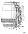
- This in Fig.1 in a partial section shown microscope objective comprises a provided with a screw thread 1.1 main version 1 with a firmly connected to this, inner cylinder sleeve 2, which has axially directed openings 3.1 to 3.4 and are arranged in the precise, axially adjustable correction frames 4.1 to 4.4.
- four correction frames 4.1 to 4.4 are provided.
- the cylinder sleeve 2 also has a corresponding number of openings. The number of components working together with the correction sockets also depends on the number of correction sockets.
- the individual optical members (not shown) are fixed, which consist of individual lenses and / or lens groups.
- the individual correction sockets 4.1 to 4.4 is outside each one, by an associated breakthrough 3.1 to 3.4 of the cylinder sleeve 2 through reaching (gripping) radially directed bolt 6.1 to 6.4 or a screw arranged.
- Each of these bolts 6.1 to 6.4 is in operative connection with a threaded ring 9.1 to 9.4 assigned to it.
- These threaded rings 9.1 to 9.4 each have an external thread 8.1 to 8.4 and are mounted only axially adjustable on the cylinder sleeve 2.
- the threaded rings 9.1 to 9.4 and the driving rings 10.1 to 10.4 can have threads of the same or different pitch, so that with the same rotation of the driving rings 10.1 to 10.4 about the optical axis 7 of the lens, the rotationally fixed threaded rings 9.1 to 9.4 different shifts in the direction of the optical axis To run.
- the individual driving rings 10.1 to 10.4 are advantageously connected by screws 13.1 to 13.3 or pins together and communicate with at least one, from the outside to be actuated and rotatable about the optical axis 7 adjusting ring 11 in operative connection.
- an adjustment ring 11 is provided, with which the driving rings 10.1 to 10.4 can be adjusted simultaneously and together by the same rotations.
- a lens (not shown), which has a plurality of adjusting rings, in which case one or more driving rings are associated with an adjusting ring, with which different axial Displacements of the correction frames can be performed with the optical members included therein.
- the objective On the object side, the objective has a securing element 14 serving for object or specimen protection, which is connected via an intermediate part 14.1 to the front correction mount 4.1 and is moved axially together with the latter.
- spring elements 12.1 to 12.4 are provided, which are the thread flanks of the operatively connected thread of the respective threaded and driving rings always press against each other.
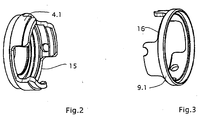
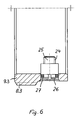
- the correction socket 4.1 of the front optical element ( Fig.2 ) and the associated first threaded ring 9.1 ( Figure 3 ) provided with recesses 15 and 16. This allows unhindered sliding of the threaded ring 9.1 and the correction frame 4.1 while simultaneously guiding the correction frame 4.1 and the threaded ring 9.1 precisely.
- lenses with a greater length can be dispensed with such interlocking, space-saving components.
- Fig. 4 and Fig. 5 show the example of the threaded ring 9.1 and the bolt 6.1 as a play-free connection according to the invention between these two components is realized. Particularly in the case of high-quality microscopic objectives, such a connection is absolutely necessary in order to achieve a virtually defect-free image.
- a compound engages the screwed in the correcting version 4.1 and radially directed bolt 6.1 in a free direction in the axial direction to the edge 19 of the threaded ring 9.1 bore 20 a.
- This bore 20 is through two, by cutouts 21 and 22 of the threaded ring 9.1 generated, resilient webs 17; 18 formed.
- Fig. 6 will be explained in more detail with reference to the threaded ring 9.3 and the bolt 6.3.
- the bolt 6.3 which with its, provided with thread 24 end 25 in the correction socket 4.3 (in Fig. 6 not shown), engages in a bore 26 of the associated, provided with the thread 8.3 threaded ring 9.3.
- the backlash ensuring intermediate member 27 is arranged between the bolt 6.3 and the wall of the bore 26 .
- this intermediate member 27 has the shape of a circular ring. Other suitable designs of the intermediate member 27 are also possible.
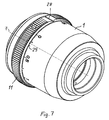
- spatially illustrated microscope objective includes, inter alia, the main frame 1 and the adjusting ring 11 rotatably mounted thereon, which has a marking 28.
- 1 Setting marks 29 are arranged, which can serve for example, the adaptation of the lens to different coverslips or to different environmental conditions.
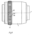
- Fig. 7 and 8th 1 illustrates that an axially directed pin 31, preferably in a bore, is arranged on an end face 30 located in the interior of the adjusting ring 11.
- This pin 31 is arranged in a defined position for marking the adjusting ring 11.
- the main frame 1 has in its interior at an end face 32 ( Fig. 10 ) extending over a peripheral area outbreak 33, the boundary surfaces as stops 34; 35 serve for the pin 31 in the rotation of the adjusting ring 11 relative to the main frame 1.
- the limitation of the outbreak 33, so the attacks 34; 35 are also oriented to the mark 28 of the adjusting ring 11.
- the angle of the breakout 33 of the main frame 1 determines the width of the overflow, which advantageously allows passing the Nulleinstellmarke in both directions within narrow limits.
- the uniformity of the overflow is automatically given by the respective orientation of the outbreak 33 to the respective adjustment mark 29 of the main version 1.
- a uniform overflow and 7undfest stops 34; 35 to limit the rotation of the adjusting ring 11 achieved.
- This arrangement is applicable to all microscope objectives with one or more adjustment rings, such. B. also micro-lenses with iris diaphragm.
Landscapes
- Physics & Mathematics (AREA)
- General Physics & Mathematics (AREA)
- Optics & Photonics (AREA)
- Chemical & Material Sciences (AREA)
- Analytical Chemistry (AREA)
- Microscoopes, Condenser (AREA)
- Lens Barrels (AREA)
- Lenses (AREA)
Abstract
Description
Die Erfindung betrifft ein Mikroskopobjektiv mit axial verstellbaren Korrekturfassungen, in welchen Linsen bzw. Linsengruppen angeordnet sind, insbesondere zur Live Cell Imaging und für Forschungen an Zellen- und Gewebekulturen. Die Erfindung ist an Mikroskopobjektiven in Verbindung mit unterschiedlichen Deckgläsern und/oder unterschiedlichen Immersionsflüssigkeiten und/oder bei unterschiedlichen Arbeitstemperaturen anwendbar.The invention relates to a microscope objective with axially adjustable correction frames, in which lenses or lens groups are arranged, in particular for live cell imaging and for research on cell and tissue cultures. The invention is applicable to microscope objectives in conjunction with different coverslips and / or different immersion liquids and / or at different operating temperatures.
Mit solchen axialen Verstellungen von optischen Gliedern in Objektiven können verschiedenartige Korrekturen vorgenommen werden, um damit ein Mikroskopieren unter verschiedenen Bedingungen mit hoher Qualität und bei hohen Abbildungsmaßstäben zu ermöglichen.With such axial displacements of optical members in objectives, various corrections can be made to allow microscopy under various conditions of high quality and at high imaging scales.
In Mikroskopobjektiven ist die axiale Verstellung von in Korrekturfassungen angeordneten optischen Gliedern in Bezug auf feststehende optische Glieder auf unterschiedliche Weise realisiert.In microscope objectives, the axial displacement of optical members arranged in correction sockets with respect to fixed optical members is realized in different ways.
So ist aus der
In der
Aus der
Eine Verstellvorrichtung für ein Objektiv ist in der
Mit diesen bekannten Mikroskopobjektiven können jedoch höchstens zwei die Abbildung beeinflussende Parameter oder durch die Umwelt bedingte Parameter und Bildfehler durch Verstellung zweier Optikglieder des Mikroskopobjektivs korrigiert oder kompensiert werden. In der Praxis ist es jedoch häufig unumgänglich, den Einfluss unterschiedlicher Deckglasdicken und verschiedener Immersionmedien auf die Abbildungsgüte und zusätzlich auch noch Umwelteinflüsse, wie beispielsweise die Temperatur, zu beachten und durch entsprechende Korrekturen weitestgehend zu kompensieren.With these known microscope objectives, however, at most two parameters influencing the image or parameters and image errors caused by the environment can be corrected or compensated by adjusting two optical elements of the microscope objective. In practice, however, it is often unavoidable to pay attention to the influence of different cover glass thicknesses and different immersion media on the image quality and, in addition, also environmental influences, such as the temperature, and to compensate as far as possible by appropriate corrections.
So liegt der Erfindung die Aufgabe zu Grunde, ein Mikroskopobjektiv mit Korrekturfassungen zu schaffen, mit welchem bei guter Korrektur der Bildfehler und bei Einhaltung einer geringen Baulänge des Objektivs eine Einstellung zwecks Kompensation von mindestens drei, die Abbildungsgüte beeinflussenden Parametern möglich ist.Thus, the invention is based on the object to provide a microscope objective with correction versions, with which with good correction of the aberrations and adherence to a small length of the lens setting for the purpose of compensation of at least three, the imaging quality influencing parameters is possible.
Erfindungsgemäß wird diese Aufgabe bei einem nach dem Oberbegriff gestalteten Mikroskopobjektiv mit den kennzeichnenden Merkmalen des ersten Anspruches gelöst.This object is achieved in a designed according to the preamble microscope objective with the characterizing features of the first claim.
In den Unteransprüchen sind weitere Ausgestaltungen und Einzelheiten des Mikroskopobjektivs offenbart.In the dependent claims further embodiments and details of the microscope objective are disclosed.
So ergibt sich eine vorteilhafte Ausgestaltung bei einer kleinen Baulänge des gesamten Objektivs, wenn eine Hauptfassung, die mit einer innen liegenden Zylinderhülse mit axial gerichteten Durchbrüchen fest verbunden ist; axial verstellbare Korrekturfassungen zur Aufnahme optischer Glieder in Form von Linsen und/oder Linsengruppen, wobei die Korrekturfassungen in der Zylinderhülse gelagert sind und an denen außen jeweils ein, durch einen zugeordneten Durchbruch der Zylinderhülse hindurch greifender, radial gerichteter Bolzen oder Schraube angeordnet ist; mit jeweils einem Bolzen in Wirkverbindung stehende, mit einem Außengewinde gleicher oder unterschiedlicher Steigung versehene Gewinderinge, welche nur axial verschiebbar auf der Zylinderhülse gelagert sind und in ein Innengewinde entsprechender Steigung von jeweils den Gewinderingen zugeordneten Mitnahmeringen eingreifen, die um die optische Achse drehbar in der Hauptfassung angeordnet sind und mit mindestens einem außen an der Hauptfassung angeordneten Einstellring in Wirkverbindung stehen und mit diesem gedreht werden können.Thus, an advantageous embodiment results in a small overall length of the entire lens when a main frame, which is firmly connected to an inner cylinder sleeve with axially directed openings; axially adjustable correction sockets for receiving optical members in the form of lenses and / or lens groups, wherein the correction frames are mounted in the cylinder sleeve and on each of which a respective, directed by an associated opening of the cylinder sleeve cross, radially directed bolt or screw is arranged; each with a bolt operatively connected, provided with an external thread of the same or different pitch threaded rings, which are mounted only axially displaceable on the cylinder sleeve and engage in an internal thread corresponding pitch of each of the threaded rings associated driving rings, which are rotatable about the optical axis in the main version are arranged and arranged with at least one outside of the main frame Adjusting ring are in operative connection and can be rotated with this.
Um eine stets spielfreie Verbindung zwischen einem Bolzen und dem zugeordneten Gewindering zu erreichen, greifen die Bolzen in eine durch mindestens einen federnden Steg gebildete, zum Rand des jeweils zugeordneten Gewinderinges hin offene Bohrung spielfrei ein.In order to achieve an always play-free connection between a bolt and the associated threaded ring, the bolts engage in a play formed by at least one resilient web, to the edge of each associated threaded ring hole open.
Um stets eine Klemmung des Bolzens in der Bohrung zu realisieren, ist vorteilhaft der Durchmesser der Bohrung kleiner als der oder gleich dem Durchmesser des in die Bohrung des Gewinderinges eingreifenden Teiles des jeweiligen Bolzens.In order to always realize a clamping of the bolt in the bore, the diameter of the bore is advantageously smaller than or equal to the diameter of the engaging in the bore of the threaded ring part of the respective bolt.
Eine spielfreie Verbindung zwischen dem Bolzen und dem dazugehörigen Gewindering ergibt sich auch vorteilhaft, wenn zwischen dem Bolzen und der Wand der Bohrung des Gewinderinges ein elastisches Zwischenglied vorgesehen ist.A play-free connection between the bolt and the associated threaded ring also results advantageous when an elastic intermediate member is provided between the bolt and the wall of the bore of the threaded ring.
Dabei ist es vorteilhaft, wenn die mit einem Einstellring in Wirkverbindung stehenden Mitnahmeringe fest miteinander verbunden und gemeinsam durch den Einstellring um die optische Achse drehbar sind.It is advantageous if the engaging ring with an adjusting ring driving engagement firmly connected to each other and are rotatable together by the adjusting ring about the optical axis.
Eine vorteilhafte Anordnung mit vielen Verstellmöglichkeiten für die optischen Glieder ergibt sich, wenn mehrere Einstellringe vorgesehen sind, welche jeweils mit mindestens einem Mitnahmering in Wirkverbindung stehen, wobei vorteilhaft die einzelnen Einstellringe unabhängig voneinander um die optische Achse des Objektivs gedreht werden können.An advantageous arrangement with many adjustment options for the optical members is obtained when a plurality of adjusting rings are provided, which are each operatively connected to at least one driving ring, wherein advantageously the individual adjusting rings can be rotated independently of each other about the optical axis of the lens.
Um unterschiedliche axiale Verstellwege der einzelnen Korrekturfassungen realisieren zu können, ist es von Vorteil, wenn die einem Einstellring zugeordneten Mitnahmeringe Gewinde gleicher oder unterschiedlicher Steigung aufweisen. Damit kann unterschiedlichen Korrekturbedingungen bei dem Objektiv Rechnung getragen werden.In order to be able to realize different axial displacement paths of the individual correction sockets, it is advantageous if the driving rings associated with a driving ring have the same or different pitch thread. Thus, different correction conditions in the lens can be taken into account.
Ferner ist es vorteilhaft, wenn zur Beseitigung des Spiels oder des toten Ganges im Gewinde zwischen den Mitnahmeringen und den zugeordneten Gewinderingen Federelemente angeordnet sind.Furthermore, it is advantageous if spring elements are arranged to eliminate the backlash or the dead gear in the thread between the driving rings and the associated threaded rings.
Vorteilhaft sind hier Druckfedern oder Elemente, welche die Funktion einer Druckfeder ausüben können, einsetzbar.Advantageously, compression springs or elements which can exert the function of a compression spring can be used here.
Es ist ferner vorteilhaft, wenn ein dem Schutz des Objektes dienendes Sicherheitselement mit der vorderen Korrekturfassung verbunden und mit dieser zusammen axial bewegbar ist.It is also advantageous if a security element serving to protect the object is connected to the front correction mount and axially movable together with the latter.
Vor allem zur Begrenzung des Verdrehbereiches des Einstellringes durch feste Anschläge ist es vorteilhaft, dass an einer im Innern des Einstellringes gelegenen Stirnfläche ein axial gerichteter Stift vorgesehen ist, daß in einer, im Innern des Objektivs gelegenen weiteren Stirnfläche der Hauptfassung ein sich über einen Umfangsbereich erstreckender Ausbruch vorgesehen ist, dessen Begrenzungsflächen Anschläge für den Stift bilden, und daß der Einstellring auf seiner Außenfläche eine Markierung und die Hauptfassung eine Skala mit Einstellmarken besitzen.Above all, to limit the range of rotation of the adjustment by fixed stops, it is advantageous that an axially directed pin is provided at a located in the interior of the adjusting end face, that in a, located in the interior of the lens further end face of the main frame extending over a peripheral region Outbreak is provided, the boundary surfaces form stops for the pin, and that the adjustment ring on its outer surface a mark and the main frame have a scale with setting marks.
Dabei ist es vorteilhaft, wenn die Positionen des axial gerichteten Stiftes und die Positionen der Anschläge zur Markierung des Einstellringes orientiert sind.It is advantageous if the positions of the axially directed pin and the positions of the stops are oriented to mark the adjusting ring.
Die Erfindung dient dazu, in einem Mikroskopobjektiv eine optische Korrektur durch axiale Verschiebung von drei oder mehr Optikgliedern mit Hilfe von sich radial bewegenden Gewinderingen mit Gewinden gleicher oder unterschiedlicher Steigung, also ohne die sonst üblichen Kurvenringe und ohne spiralförmige Nuten in einzelnen Ringen zu verwenden, zu realisieren.The invention serves to use in a microscope objective an optical correction by axial displacement of three or more optical members by means of radially moving threaded rings with threads of the same or different pitch, so without the usual curve rings and without spiral grooves in individual rings realize.
Weiterhin können auch neben den optischen Korrekturen Anpassungen an unterschiedliche Beobachtungsbedingungen vorgenommen werden. So wird das Arbeiten mit unterschiedlichen Immersionsmedien, z.B. Glyzerin oder Wasser, und auch in unterschiedlichen Temperaturbereichen, z.B. bei 23°C oder 37°C, und das Mikroskopieren mit verschiedenen Deckgläsern unterschiedlicher Dicke und Toleranz wesentlich erleichtert. Weiterhin ist bei diesem Objektiv eine geringe Baulänge in der Größenordnung von 50 mm erreichbar. Bei einem geringen Arbeitsabstand vom etwa 0,18 mm ist auch ein zuverlässiger Präparate- oder Objektschutz in einfacher Weise realisierbar.Furthermore, in addition to the optical corrections adjustments to different observation conditions can be made. Thus, working with different immersion media, e.g. Glycerine or water, and also in different temperature ranges, e.g. at 23 ° C or 37 ° C, and greatly facilitated the microscopy with different coverslips of different thickness and tolerance. Furthermore, in this lens, a short overall length of the order of 50 mm can be achieved. At a low working distance of about 0.18 mm and a reliable preparations or object protection can be realized in a simple manner.
Die Erfindung soll nachstehend an einem Ausführungsbeispiel näher erläutert werden. In der Zeichnung zeigen:
- Fig.1
- einen teilweisen Längsschnitt durch ein erfindungsgemäßes Mikroskopobjektiv,
- Fig. 2
- ein weiteres Fassungsteil des vorderen optischen Gliedes,
- Fig. 3
- ein Fassungsteil des vorderen optischen Gliedes,
- Fig. 4
- einen Gewindering mit geöffneter Bohrung und federnden Stegen,
- Fig. 5
- einen Gewindering mit eingreifendem Bolzen,
- Fig. 6
- einen Gewindering mit Bolzen und elastischem Element,
- Fig. 7
- eine Ansicht eines Objektivs mit Hauptfassung und Einstellring,
- Fig. 8
- ein Objektiv mit geöffnetem Einstellring,
- Fig. 9
- einen Einstellring und
- Fig. 10
- die Hauptfassung mit Ausbruch und Skala.
- Fig.1
- a partial longitudinal section through a microscope objective according to the invention,
- Fig. 2
- another frame part of the front optical member,
- Fig. 3
- a socket part of the front optical member,
- Fig. 4
- a threaded ring with open bore and resilient webs,
- Fig. 5
- a threaded ring with an engaging pin,
- Fig. 6
- a threaded ring with bolt and elastic element,
- Fig. 7
- a view of a lens with main frame and adjusting ring,
- Fig. 8
- a lens with open adjustment ring,
- Fig. 9
- a setting ring and
- Fig. 10
- the main version with outbreak and scale.
Das in
Die Gewinderinge 9.1 bis 9.4 und die Mitnahmeringe 10.1 bis 10.4 können Gewinde gleicher oder unterschiedlicher Steigung besitzen, so dass bei gleicher Drehung der Mitnahmeringe 10.1 bis 10.4 um die optische Achse 7 des Objektivs die drehfesten Gewinderinge 9.1 bis 9.4 unterschiedliche Verschiebungen in Richtung der optischen Achse 7 ausführen.The threaded rings 9.1 to 9.4 and the driving rings 10.1 to 10.4 can have threads of the same or different pitch, so that with the same rotation of the driving rings 10.1 to 10.4 about the
Die einzelnen Mitnahmeringe 10.1 bis 10.4 sind vorteilhaft durch Schrauben 13.1 bis 13.3 oder Stifte miteinander verbunden und stehen mit mindestens einem, von außen zu betätigenden und um die optische Achse 7 drehbaren Einstellring 11 in Wirkverbindung.The individual driving rings 10.1 to 10.4 are advantageously connected by screws 13.1 to 13.3 or pins together and communicate with at least one, from the outside to be actuated and rotatable about the
Bei dem Mikroskopobjektiv nach
Objektseitig besitzt das Objektiv ein dem Objekt- oder Präparateschutz dienendes Sicherungselement 14, welches über ein Zwischenteil 14.1 mit der vorderen Korrekturfassung 4.1 verbunden ist und mit dieser zusammen axial bewegt wird.On the object side, the objective has a securing
Um das Spiel oder den toten Gang zwischen den miteinander im Eingriff stehenden Gewinden der Mitnahmeringe 10.1 bis 10.4 und der zugeordneten Gewinderinge 9.1 bis 9.4 zu eliminieren, sind Federelemente 12.1 bis 12.4 vorgesehen, welche die Gewindeflanken der in Wirkverbindung stehenden Gewinde der betreffenden Gewinde- und Mitnahmeringe stets gegeneinander drücken.In order to eliminate the play or the dead gear between the mutually engaging threads of the driving rings 10.1 to 10.4 and the associated threaded rings 9.1 to 9.4, spring elements 12.1 to 12.4 are provided, which are the thread flanks of the operatively connected thread of the respective threaded and driving rings always press against each other.
Insbesondere bei der Realisierung einer geringen Objektivlänge in der Größenordnung von 50 mm und darunter erfordern der Objekt- und Präparateschutz und die axial beweglichen Korrekturfassungen 4.1 bis 4.4 besondere Maßnahmen. Hierzu sind die Korrekturfassung 4.1 des vorderen optischen Gliedes (
Eine Verstellung der Korrekturfassungen 4.1 bis 4.4 wird in folgender Weise realisiert:
- Die Korrekturfassungen 4.1 bis 4.4, in denen die optischen Glieder (nicht dargestellt) gefasst sind, und die die Außengewinde 8.1 bis 8.4 tragenden Gewinderinge 9.1 bis 9.4 sind durch die Bolzen 6.1 bis 6.4 verbunden. Diese Bolzen 6.1 bis 6.4 sind durch die axialen Durchbrüche 3.1 bis 3.4 der fest in
der Hauptfassung 1 angeordneten Zylinderhülse 2 hindurch geführt und besitzen somit zusammen mit den Gewinderingen 9.1 bis 9.4 und den Korrekturfassungen 4.1 bis 4.4 nur eine Verstell- bzw. Verschiebungsmöglichkeit in Richtung der optischen Achse 7. Eine Drehung um dieAchse 7 ist nicht möglich. Durch Drehung des Einstellringes 11 um die optische Achse 7 werden die miteinander verbundenen Mitnahmeringe 10.1 bis 10.4 mit um dieAchse 7 gedreht. Durch Drehung der Mitnahmeringe 10.1 bis 10.4 mittels des Einstellringes 11 wird infolge des Zusammenwirkens des Innengewindes dieser Mitnahmeringe mit den entsprechenden Außengewinden 8.1 bis 8.4 der verdrehfest angeordneten Gewinderinge 9.1 bis 9.4 eine axiale Verstellung der Korrekturfassungen 4.1 bis 4.4 und der darin gefassten optischen Glieder realisiert.
- The correction frames 4.1 to 4.4, in which the optical members (not shown) are taken, and the outer threads 8.1 to 8.4 bearing threaded rings 9.1 to 9.4 are connected by the bolts 6.1 to 6.4. These bolts 6.1 to 6.4 are guided through the axial openings 3.1 to 3.4 of the fixedly arranged in the
main frame 1cylinder sleeve 2 and thus have together with the threaded rings 9.1 to 9.4 and the correction versions 4.1 to 4.4 only an adjustment or displacement in the direction ofoptical axis 7. A rotation about theaxis 7 is not possible. By rotation of the adjustingring 11 about theoptical axis 7, the interconnected driving rings 10.1 to 10.4 are rotated about theaxis 7. By rotation of the entrainment rings 10.1 to 10.4 by means of the adjustingring 11, an axial adjustment of the correction frames 4.1 to 4.4 and the optical elements contained therein is realized due to the interaction of the internal thread of these driving rings with the corresponding external threads 8.1 to 8.4 of the rotationally arranged threaded rings 9.1 to 9.4.
Möglich wäre es auch, nur einen federnden Steg vorzusehen. Die Herstellung gestaltete sich dadurch günstiger. Jedoch würde die Dreipunktanlage dadurch verloren gehen.It would also be possible to provide only a resilient web. The production was thus cheaper. However, the three-point system would be lost.
Das in der
In den
- 11
- Hauptfassungmain version
- 22
- Zylinderhülsecylinder sleeve
- 3.1 bis 3.43.1 to 3.4
- Durchbrüchebreakthroughs
- 4.1 bis 4.44.1 to 4.4
- Korrekturfassungencorrection mounts
- 6.1 bis 6.46.1 to 6.4
- Bolzenbolt
- 77
- optische Achseoptical axis
- 8.1 bis 8.48.1 to 8.4
- Außengewindeexternal thread
- 9.1 bis 9.49.1 to 9.4
- Gewinderingethreaded rings
- 10.1 bis 10.410.1 to 10.4
- Mitnahmeringedriver rings
- 1111
- Einstellringadjustment
- 12.1 bis 12.412.1 to 12.4
- Federelementespring elements
- 13.1 bis 13.413.1 to 13.4
- Schraubenscrew
- 1414
- Sicherungselementfuse element
- 14.114.1
- Zwischenteilintermediate part
- 15, 1615, 16
- Aussparungenrecesses
- 17, 1817, 18
- StegeStege
- 1919
- Randedge
- 2020
- Bohrungdrilling
- 21; 2221; 22
- Ausfräsungenmillings
- 2424
- Gewindethread
- 2525
- EndeThe End
- 2626
- Bohrungdrilling
- 2727
- Zwischengliedintermediary
- 2828
- Markierungmark
- 2929
- Einstellmarkesetting mark
- 3030
- Stirnflächeface
- 3131
- Stiftpen
- 3232
- Stirnflächeface
- 3333
- Ausbruchoutbreak
- 34; 3534; 35
- Anschlägeattacks
Claims (12)
- Microscope objective with axially adjustable corrective mounts (4.1 to 4.4) for adapting to different parameters influencing the imaging quality, the axial adjustment of the corrective mounts (4.1 to 4.4) relative to a fixed main mount (1) being implementable by a setting ring (11) arranged outside on the main mount (1) via a bolt (6.1 to 6.4) which is arranged in the respective corrective mount (4.1 to 4.4), is directed radially relative to the optical axis of the objective and engages in openings in threaded rings (9.1 to 9.4), the objective having at least three corrective mounts (4.1 to 4.4), and the corrective mounts (4.1 to 4.4) being adjustable in the direction of the optical axis (7) by means of the at least one setting ring (11) without an additional rotation about said optical axis (7), characterized in that the bolts (6.1 to 6.4) engage without play in an open bore (20) which is formed by at least one resilient web (17 or 18) and is open towards the edge (19) of the respectively assigned threaded ring (9.1 to 9.4).
- Microscope objective according to Claim 1, comprising a main mount (1) which is fixedly connected to an inner cylindrical sleeve (2) with axially directed openings (3.1 to 3.4), and
axially adjustable corrective mounts (4.1 to 4.4) for holding optical elements which are axially displaceably mounted in the cylindrical sleeve (2), and on which there is respectively arranged outside a radially directed bolt (6.1 to 6.4) or screw reaching through an assigned opening (3.1 to 3.4) in the cylindrical sleeve (2), and comprising
threaded rings (9.1 to 9.4) which are respectively operationally connected to a bolt (6.1 to 6.4), are provided with an outer thread (8.1 to 8.4) of the same or different pitch, are supported only axially displaceably on the cylindrical sleeve (2), and engage in an inner thread, of corresponding pitch, of driving rings (10.1 to 10.4) which are respectively assigned to the threaded rings (9.1 to 9.4), are arranged rotatably about the optical axis (7) in the main mount (1) and are operationally connected to at least one setting ring (11), arranged outside on the main mount (1), and can be rotated together with said setting ring. - Microscope objective according to Claim 2, characterized in that the driving rings (10.1 to 10.4) are operationally connected to a setting ring (11), are fixedly connected to one another and can be rotated together about the optical axis (7) by the setting ring (11).
- Microscope objective according to one of Claims 1 to 3, characterized in that a plurality of setting rings (11) are provided which are respectively operationally connected to at least one driving ring (10.1 to 10.4).
- Microscope objective according to one of Claims 1 to 4, characterized in that the driving rings (10.1 to 10.4) assigned to a setting ring (11) have threads of the same or different pitch.
- Microscope objective according to one of Claims 1 to 5, characterized in that spring elements (12.1 to 12.4) are arranged for the purpose of removing the play or the dead travel in the thread between the driving rings (10.1 to 10.4) and the assigned threaded rings (9.1 to 9.4).
- Microscope objective according to Claim 6, characterized in that the spring elements (12.1 to 12.4) are pressure springs.
- Microscope objective according to one of Claims 1 to 7, characterized in that connected to the front corrective mount (4.1) is a safety element (14) which serves to protect the object and which can be moved axially together with the corrective mount (4.1).
- Microscope objective according to Claim 1, characterized in that the diameter of the bore (20) is less than or equal to the diameter of the part, engaging in the bore (20), of the respective bolt (6.1 to 6.4).
- Microscope objective according to Claim 1, characterized in that an elastic intermediate element is provided between the bolt (6.1 to 6.4) and the associated bore (20) of the respective threaded ring (9.1 to 9.4).
- Microscope objective according to one of Claims 1 to 8, characterized in that an axially directed pin (31) is provided on an end face (30) situated in the interior of the setting ring (11), in that provided in a further end face (32), situated in the interior of the objective, of the main mount (1) is a cutout (33) which extends over a peripheral region and whose bounding surfaces form stops (34; 35) for the pin (31), and in that the setting ring (11) has a marking (28), and the main mount (1) has a scale with setting marks (29) over at least a part of its circumference.
- Microscope objective according to Claim 11, characterized in that the positions on the axially directed pin (31) and the positions of the stops (34; 35) are orientated in relation to the marking (28) of the setting ring (11).
Applications Claiming Priority (2)
| Application Number | Priority Date | Filing Date | Title |
|---|---|---|---|
| DE10361911 | 2003-12-24 | ||
| DE10361911A DE10361911A1 (en) | 2003-12-24 | 2003-12-24 | Microscope objective with axially adjustable correction sockets |
Publications (2)
| Publication Number | Publication Date |
|---|---|
| EP1548482A1 EP1548482A1 (en) | 2005-06-29 |
| EP1548482B1 true EP1548482B1 (en) | 2011-09-28 |
Family
ID=34530418
Family Applications (1)
| Application Number | Title | Priority Date | Filing Date |
|---|---|---|---|
| EP04029779A Expired - Lifetime EP1548482B1 (en) | 2003-12-24 | 2004-12-16 | Microscope objective with axially adjustable corrective mounts |
Country Status (5)
| Country | Link |
|---|---|
| US (1) | US7259924B2 (en) |
| EP (1) | EP1548482B1 (en) |
| JP (1) | JP2005189856A (en) |
| AT (1) | ATE526602T1 (en) |
| DE (1) | DE10361911A1 (en) |
Families Citing this family (7)
| Publication number | Priority date | Publication date | Assignee | Title |
|---|---|---|---|---|
| DE102005034442A1 (en) * | 2005-07-22 | 2007-02-22 | Carl Zeiss Microimaging Gmbh | Microscope objective system |
| DE102005034441A1 (en) * | 2005-07-22 | 2007-02-22 | Carl Zeiss Microimaging Gmbh | microscope objective |
| US8792632B2 (en) | 2009-08-13 | 2014-07-29 | Genesys Telecommunications Laboratories, Inc. | System and methods for scheduling and optimizing inbound call flow to a call center |
| EP2696230A4 (en) * | 2011-04-02 | 2014-08-27 | Jin Luo | Additional knurled ring for optical lens |
| DE102011051677B4 (en) * | 2011-07-08 | 2016-12-01 | Leica Microsystems Cms Gmbh | Microscope lens and microscope |
| CN112034583B (en) * | 2020-08-25 | 2022-11-11 | 长春长光智欧科技有限公司 | High-integration complete machine device for microscope objective |
| CN114295005A (en) * | 2021-11-30 | 2022-04-08 | 航天科工微电子系统研究院有限公司 | Reference mirror adjusting device |
Family Cites Families (19)
| Publication number | Priority date | Publication date | Assignee | Title |
|---|---|---|---|---|
| US2078858A (en) * | 1935-02-08 | 1937-04-27 | Lyman Gun Sight Corp | Telescope sight |
| US2437775A (en) * | 1946-02-11 | 1948-03-16 | Williams William Ewart | Optical micrometer for measuring the thickness of transparent or translucent bodies |
| US2529894A (en) * | 1948-05-28 | 1950-11-14 | Eastman Kodak Co | Objective mount |
| AT170000B (en) * | 1948-10-01 | 1951-12-27 | Ernst Leitz Ges M B H | Mount for micro lenses |
| US2945419A (en) * | 1955-12-06 | 1960-07-19 | Ednalite Optical Company Inc | Variable focal length lens system for movie cameras |
| AT241152B (en) * | 1962-02-28 | 1965-07-12 | Voigtlaender Ag | Lens variable focal length |
| US3213539A (en) * | 1963-03-04 | 1965-10-26 | Redfield Gun Sight Company | Adjustable reticle assembly for optical sighting devices |
| US3549230A (en) | 1967-03-15 | 1970-12-22 | Nippon Kogaku Kk | Zooming device for adjusting the light amount of a formed image |
| DE1932681A1 (en) * | 1969-06-27 | 1971-01-14 | Leitz Ernst Gmbh | Socket for optical systems with at least two axially displaceable system parts |
| JP2505192B2 (en) * | 1987-03-10 | 1996-06-05 | オリンパス光学工業株式会社 | Zoom mechanism |
| DE3812745C2 (en) * | 1988-04-16 | 1997-07-10 | Zeiss Carl Fa | Microscope objective with a device for setting different cover glass thicknesses |
| JPH02220014A (en) * | 1989-02-21 | 1990-09-03 | Olympus Optical Co Ltd | Zoom lens barrel |
| JP3291746B2 (en) * | 1991-11-20 | 2002-06-10 | 株式会社ニコン | Zoom lens system |
| DE4323721C2 (en) * | 1993-07-15 | 1996-03-21 | Leica Mikroskopie & Syst | Microscope lens with a correction frame |
| JPH10142512A (en) * | 1996-11-12 | 1998-05-29 | Nikon Corp | Microscope objective lens |
| DE19804470C1 (en) * | 1998-02-05 | 1999-08-26 | Leica Microsystems | Microscope objective with correction mounting |
| DE19947378A1 (en) * | 1998-10-09 | 2000-04-13 | Zeiss Carl Fa | Adjustment device for lens is provided with axially movable optical member connected to main frame by sliding frame and incorporates linear drive producing linear movement in first axial direction. |
| DE10209403B9 (en) * | 2002-03-04 | 2007-03-22 | Carl Zeiss | Video observation system |
| DE10361912A1 (en) * | 2003-12-24 | 2005-07-21 | Carl Zeiss Jena Gmbh | Microscope objective with axially adjustable correction sockets |
-
2003
- 2003-12-24 DE DE10361911A patent/DE10361911A1/en not_active Withdrawn
-
2004
- 2004-12-16 EP EP04029779A patent/EP1548482B1/en not_active Expired - Lifetime
- 2004-12-16 AT AT04029779T patent/ATE526602T1/en active
- 2004-12-21 JP JP2004369476A patent/JP2005189856A/en active Pending
- 2004-12-22 US US11/020,710 patent/US7259924B2/en not_active Expired - Lifetime
Also Published As
| Publication number | Publication date |
|---|---|
| ATE526602T1 (en) | 2011-10-15 |
| US20050141109A1 (en) | 2005-06-30 |
| EP1548482A1 (en) | 2005-06-29 |
| US7259924B2 (en) | 2007-08-21 |
| DE10361911A1 (en) | 2005-07-21 |
| JP2005189856A (en) | 2005-07-14 |
Similar Documents
| Publication | Publication Date | Title |
|---|---|---|
| DE102008026774B4 (en) | Control device for actuators in microscope objectives | |
| DE102011051677B4 (en) | Microscope lens and microscope | |
| DE102011117743B4 (en) | Microscope objective with at least one lens group displaceable in the direction of the optical axis | |
| DE2933829C2 (en) | Tube for one objective | |
| DE3650509T2 (en) | Zoom microscope with crank and linkage mechanism | |
| DE4104548C2 (en) | Zoom lens barrel | |
| DE4033151C2 (en) | Binocular binoculars | |
| DE3023595C2 (en) | Varifocal lens mount | |
| DE102007030579B4 (en) | Lateral adjustable socket for optical elements | |
| WO2018073167A1 (en) | Adapter device and camera lens | |
| DE19804470C1 (en) | Microscope objective with correction mounting | |
| DE102012214703A1 (en) | Surgical microscope objective with adjustable cutting distance | |
| DE2903892A1 (en) | HOLDER FOR OPTICAL LENS ARRANGEMENTS | |
| EP1548482B1 (en) | Microscope objective with axially adjustable corrective mounts | |
| EP0660942B1 (en) | Microscope objective with a correcting mount | |
| EP1548483B1 (en) | Microscope objective with axially adjustable corrective mounts | |
| AT513008B1 (en) | Adapter sleeve for observation telescope | |
| DE102018127469B4 (en) | Positioning unit and observation device | |
| DE3026188A1 (en) | MECHANICAL VERSION FOR A ZOOM LENS COMPOSITION | |
| DE3013173A1 (en) | ZOOM LENS FOCUS WITH FOCUS | |
| DE2263756C2 (en) | Varifocal lens arrangement | |
| EP1426808B1 (en) | Endoscope eyepiece | |
| WO1988001434A1 (en) | Movable specimen holder for a particle radiation microscope | |
| DE10015186B4 (en) | lens Mounting | |
| DE102018103441B4 (en) | Holding chuck for machines for the production of glass containers |
Legal Events
| Date | Code | Title | Description |
|---|---|---|---|
| PUAI | Public reference made under article 153(3) epc to a published international application that has entered the european phase |
Free format text: ORIGINAL CODE: 0009012 |
|
| 17P | Request for examination filed |
Effective date: 20041216 |
|
| AK | Designated contracting states |
Kind code of ref document: A1 Designated state(s): AT BE BG CH CY CZ DE DK EE ES FI FR GB GR HU IE IS IT LI LT LU MC NL PL PT RO SE SI SK TR |
|
| AX | Request for extension of the european patent |
Extension state: AL BA HR LV MK YU |
|
| AKX | Designation fees paid |
Designated state(s): AT BE BG CH CY CZ DE DK EE ES FI FR GB GR HU IE IS IT LI LT LU MC NL PL PT RO SE SI SK TR |
|
| GRAP | Despatch of communication of intention to grant a patent |
Free format text: ORIGINAL CODE: EPIDOSNIGR1 |
|
| GRAS | Grant fee paid |
Free format text: ORIGINAL CODE: EPIDOSNIGR3 |
|
| RIN1 | Information on inventor provided before grant (corrected) |
Inventor name: FAHLBUSCH, INGO Inventor name: NOLTE, DETMAR Inventor name: HERBST, GEORG Inventor name: MOLLENHAUER, GERHARD Inventor name: SHI, RENHU Inventor name: SEBODE, WOLFGANG Inventor name: HARTJE, WOLFGANG Inventor name: DAMBECK, MARION Inventor name: GUENTHER, THOMAS Inventor name: BUSSE, ANDREAS Inventor name: WILHELM, ADOLPH Inventor name: WAHL, HUBERT |
|
| GRAA | (expected) grant |
Free format text: ORIGINAL CODE: 0009210 |
|
| RAP1 | Party data changed (applicant data changed or rights of an application transferred) |
Owner name: CARL ZEISS MICROIMAGING GMBH |
|
| AK | Designated contracting states |
Kind code of ref document: B1 Designated state(s): AT BE BG CH CY CZ DE DK EE ES FI FR GB GR HU IE IS IT LI LT LU MC NL PL PT RO SE SI SK TR |
|
| REG | Reference to a national code |
Ref country code: GB Ref legal event code: FG4D Free format text: NOT ENGLISH |
|
| REG | Reference to a national code |
Ref country code: CH Ref legal event code: EP |
|
| REG | Reference to a national code |
Ref country code: IE Ref legal event code: FG4D |
|
| REG | Reference to a national code |
Ref country code: DE Ref legal event code: R096 Ref document number: 502004012899 Country of ref document: DE Effective date: 20111124 |
|
| REG | Reference to a national code |
Ref country code: NL Ref legal event code: VDEP Effective date: 20110928 |
|
| PG25 | Lapsed in a contracting state [announced via postgrant information from national office to epo] |
Ref country code: FI Free format text: LAPSE BECAUSE OF FAILURE TO SUBMIT A TRANSLATION OF THE DESCRIPTION OR TO PAY THE FEE WITHIN THE PRESCRIBED TIME-LIMIT Effective date: 20110928 Ref country code: SE Free format text: LAPSE BECAUSE OF FAILURE TO SUBMIT A TRANSLATION OF THE DESCRIPTION OR TO PAY THE FEE WITHIN THE PRESCRIBED TIME-LIMIT Effective date: 20110928 Ref country code: LT Free format text: LAPSE BECAUSE OF FAILURE TO SUBMIT A TRANSLATION OF THE DESCRIPTION OR TO PAY THE FEE WITHIN THE PRESCRIBED TIME-LIMIT Effective date: 20110928 |
|
| LTIE | Lt: invalidation of european patent or patent extension |
Effective date: 20110928 |
|
| PG25 | Lapsed in a contracting state [announced via postgrant information from national office to epo] |
Ref country code: CY Free format text: LAPSE BECAUSE OF FAILURE TO SUBMIT A TRANSLATION OF THE DESCRIPTION OR TO PAY THE FEE WITHIN THE PRESCRIBED TIME-LIMIT Effective date: 20110928 Ref country code: GR Free format text: LAPSE BECAUSE OF FAILURE TO SUBMIT A TRANSLATION OF THE DESCRIPTION OR TO PAY THE FEE WITHIN THE PRESCRIBED TIME-LIMIT Effective date: 20111229 Ref country code: SI Free format text: LAPSE BECAUSE OF FAILURE TO SUBMIT A TRANSLATION OF THE DESCRIPTION OR TO PAY THE FEE WITHIN THE PRESCRIBED TIME-LIMIT Effective date: 20110928 |
|
| REG | Reference to a national code |
Ref country code: IE Ref legal event code: FD4D |
|
| PG25 | Lapsed in a contracting state [announced via postgrant information from national office to epo] |
Ref country code: IS Free format text: LAPSE BECAUSE OF FAILURE TO SUBMIT A TRANSLATION OF THE DESCRIPTION OR TO PAY THE FEE WITHIN THE PRESCRIBED TIME-LIMIT Effective date: 20120128 Ref country code: CZ Free format text: LAPSE BECAUSE OF FAILURE TO SUBMIT A TRANSLATION OF THE DESCRIPTION OR TO PAY THE FEE WITHIN THE PRESCRIBED TIME-LIMIT Effective date: 20110928 Ref country code: SK Free format text: LAPSE BECAUSE OF FAILURE TO SUBMIT A TRANSLATION OF THE DESCRIPTION OR TO PAY THE FEE WITHIN THE PRESCRIBED TIME-LIMIT Effective date: 20110928 |
|
| PG25 | Lapsed in a contracting state [announced via postgrant information from national office to epo] |
Ref country code: IT Free format text: LAPSE BECAUSE OF FAILURE TO SUBMIT A TRANSLATION OF THE DESCRIPTION OR TO PAY THE FEE WITHIN THE PRESCRIBED TIME-LIMIT Effective date: 20110928 Ref country code: EE Free format text: LAPSE BECAUSE OF FAILURE TO SUBMIT A TRANSLATION OF THE DESCRIPTION OR TO PAY THE FEE WITHIN THE PRESCRIBED TIME-LIMIT Effective date: 20110928 Ref country code: NL Free format text: LAPSE BECAUSE OF FAILURE TO SUBMIT A TRANSLATION OF THE DESCRIPTION OR TO PAY THE FEE WITHIN THE PRESCRIBED TIME-LIMIT Effective date: 20110928 Ref country code: PT Free format text: LAPSE BECAUSE OF FAILURE TO SUBMIT A TRANSLATION OF THE DESCRIPTION OR TO PAY THE FEE WITHIN THE PRESCRIBED TIME-LIMIT Effective date: 20120130 Ref country code: RO Free format text: LAPSE BECAUSE OF FAILURE TO SUBMIT A TRANSLATION OF THE DESCRIPTION OR TO PAY THE FEE WITHIN THE PRESCRIBED TIME-LIMIT Effective date: 20110928 |
|
| BERE | Be: lapsed |
Owner name: CARL ZEISS MICROIMAGING G.M.B.H. Effective date: 20111231 |
|
| PG25 | Lapsed in a contracting state [announced via postgrant information from national office to epo] |
Ref country code: IE Free format text: LAPSE BECAUSE OF FAILURE TO SUBMIT A TRANSLATION OF THE DESCRIPTION OR TO PAY THE FEE WITHIN THE PRESCRIBED TIME-LIMIT Effective date: 20110928 Ref country code: MC Free format text: LAPSE BECAUSE OF NON-PAYMENT OF DUE FEES Effective date: 20111231 Ref country code: DK Free format text: LAPSE BECAUSE OF FAILURE TO SUBMIT A TRANSLATION OF THE DESCRIPTION OR TO PAY THE FEE WITHIN THE PRESCRIBED TIME-LIMIT Effective date: 20110928 |
|
| REG | Reference to a national code |
Ref country code: CH Ref legal event code: PL |
|
| PLBE | No opposition filed within time limit |
Free format text: ORIGINAL CODE: 0009261 |
|
| STAA | Information on the status of an ep patent application or granted ep patent |
Free format text: STATUS: NO OPPOSITION FILED WITHIN TIME LIMIT |
|
| PG25 | Lapsed in a contracting state [announced via postgrant information from national office to epo] |
Ref country code: PL Free format text: LAPSE BECAUSE OF FAILURE TO SUBMIT A TRANSLATION OF THE DESCRIPTION OR TO PAY THE FEE WITHIN THE PRESCRIBED TIME-LIMIT Effective date: 20110928 |
|
| 26N | No opposition filed |
Effective date: 20120629 |
|
| REG | Reference to a national code |
Ref country code: DE Ref legal event code: R097 Ref document number: 502004012899 Country of ref document: DE Effective date: 20120629 |
|
| PG25 | Lapsed in a contracting state [announced via postgrant information from national office to epo] |
Ref country code: BE Free format text: LAPSE BECAUSE OF NON-PAYMENT OF DUE FEES Effective date: 20111231 Ref country code: CH Free format text: LAPSE BECAUSE OF NON-PAYMENT OF DUE FEES Effective date: 20111231 Ref country code: LI Free format text: LAPSE BECAUSE OF NON-PAYMENT OF DUE FEES Effective date: 20111231 |
|
| REG | Reference to a national code |
Ref country code: AT Ref legal event code: MM01 Ref document number: 526602 Country of ref document: AT Kind code of ref document: T Effective date: 20111216 |
|
| REG | Reference to a national code |
Ref country code: DE Ref legal event code: R081 Ref document number: 502004012899 Country of ref document: DE Owner name: CARL ZEISS MICROSCOPY GMBH, DE Free format text: FORMER OWNER: CARL ZEISS JENA GMBH, 07745 JENA, DE Effective date: 20111004 Ref country code: DE Ref legal event code: R081 Ref document number: 502004012899 Country of ref document: DE Owner name: CARL ZEISS MICROSCOPY GMBH, DE Free format text: FORMER OWNER: CARL ZEISS MICROIMAGING GMBH, 07745 JENA, DE Effective date: 20130204 |
|
| PG25 | Lapsed in a contracting state [announced via postgrant information from national office to epo] |
Ref country code: ES Free format text: LAPSE BECAUSE OF FAILURE TO SUBMIT A TRANSLATION OF THE DESCRIPTION OR TO PAY THE FEE WITHIN THE PRESCRIBED TIME-LIMIT Effective date: 20120108 |
|
| PG25 | Lapsed in a contracting state [announced via postgrant information from national office to epo] |
Ref country code: LU Free format text: LAPSE BECAUSE OF NON-PAYMENT OF DUE FEES Effective date: 20111216 |
|
| PG25 | Lapsed in a contracting state [announced via postgrant information from national office to epo] |
Ref country code: BG Free format text: LAPSE BECAUSE OF FAILURE TO SUBMIT A TRANSLATION OF THE DESCRIPTION OR TO PAY THE FEE WITHIN THE PRESCRIBED TIME-LIMIT Effective date: 20111228 Ref country code: AT Free format text: LAPSE BECAUSE OF NON-PAYMENT OF DUE FEES Effective date: 20111216 |
|
| PG25 | Lapsed in a contracting state [announced via postgrant information from national office to epo] |
Ref country code: TR Free format text: LAPSE BECAUSE OF FAILURE TO SUBMIT A TRANSLATION OF THE DESCRIPTION OR TO PAY THE FEE WITHIN THE PRESCRIBED TIME-LIMIT Effective date: 20110928 |
|
| PG25 | Lapsed in a contracting state [announced via postgrant information from national office to epo] |
Ref country code: HU Free format text: LAPSE BECAUSE OF FAILURE TO SUBMIT A TRANSLATION OF THE DESCRIPTION OR TO PAY THE FEE WITHIN THE PRESCRIBED TIME-LIMIT Effective date: 20110928 |
|
| REG | Reference to a national code |
Ref country code: FR Ref legal event code: PLFP Year of fee payment: 12 |
|
| REG | Reference to a national code |
Ref country code: FR Ref legal event code: PLFP Year of fee payment: 13 |
|
| REG | Reference to a national code |
Ref country code: FR Ref legal event code: PLFP Year of fee payment: 14 |
|
| PGFP | Annual fee paid to national office [announced via postgrant information from national office to epo] |
Ref country code: GB Payment date: 20211221 Year of fee payment: 18 Ref country code: FR Payment date: 20211224 Year of fee payment: 18 Ref country code: DE Payment date: 20211210 Year of fee payment: 18 |
|
| REG | Reference to a national code |
Ref country code: DE Ref legal event code: R119 Ref document number: 502004012899 Country of ref document: DE |
|
| GBPC | Gb: european patent ceased through non-payment of renewal fee |
Effective date: 20221216 |
|
| PG25 | Lapsed in a contracting state [announced via postgrant information from national office to epo] |
Ref country code: GB Free format text: LAPSE BECAUSE OF NON-PAYMENT OF DUE FEES Effective date: 20221216 Ref country code: DE Free format text: LAPSE BECAUSE OF NON-PAYMENT OF DUE FEES Effective date: 20230701 |
|
| PG25 | Lapsed in a contracting state [announced via postgrant information from national office to epo] |
Ref country code: FR Free format text: LAPSE BECAUSE OF NON-PAYMENT OF DUE FEES Effective date: 20221231 |