EP1548458A2 - In einem Kraftfahrzeug eingebautes Radar - Google Patents
In einem Kraftfahrzeug eingebautes Radar Download PDFInfo
- Publication number
- EP1548458A2 EP1548458A2 EP04019181A EP04019181A EP1548458A2 EP 1548458 A2 EP1548458 A2 EP 1548458A2 EP 04019181 A EP04019181 A EP 04019181A EP 04019181 A EP04019181 A EP 04019181A EP 1548458 A2 EP1548458 A2 EP 1548458A2
- Authority
- EP
- European Patent Office
- Prior art keywords
- antenna
- reception
- vehicle
- transmission
- antennas
- Prior art date
- Legal status (The legal status is an assumption and is not a legal conclusion. Google has not performed a legal analysis and makes no representation as to the accuracy of the status listed.)
- Withdrawn
Links
- 230000005540 biological transmission Effects 0.000 claims abstract description 91
- 238000001514 detection method Methods 0.000 claims description 19
- 238000012545 processing Methods 0.000 claims description 18
- 230000005855 radiation Effects 0.000 claims description 6
- 230000008034 disappearance Effects 0.000 claims 1
- 238000000034 method Methods 0.000 description 26
- 238000010586 diagram Methods 0.000 description 15
- 230000000116 mitigating effect Effects 0.000 description 5
- 238000001228 spectrum Methods 0.000 description 5
- 238000006243 chemical reaction Methods 0.000 description 4
- 238000004891 communication Methods 0.000 description 4
- 239000006096 absorbing agent Substances 0.000 description 2
- 239000000463 material Substances 0.000 description 2
- 238000005259 measurement Methods 0.000 description 2
- 238000004092 self-diagnosis Methods 0.000 description 2
- 230000003044 adaptive effect Effects 0.000 description 1
- 230000000694 effects Effects 0.000 description 1
- 238000012986 modification Methods 0.000 description 1
- 230000004048 modification Effects 0.000 description 1
- 230000010355 oscillation Effects 0.000 description 1
- 230000010363 phase shift Effects 0.000 description 1
- 239000007787 solid Substances 0.000 description 1
- 230000003595 spectral effect Effects 0.000 description 1
- 238000010183 spectrum analysis Methods 0.000 description 1
Images


Classifications
-
- G—PHYSICS
- G01—MEASURING; TESTING
- G01S—RADIO DIRECTION-FINDING; RADIO NAVIGATION; DETERMINING DISTANCE OR VELOCITY BY USE OF RADIO WAVES; LOCATING OR PRESENCE-DETECTING BY USE OF THE REFLECTION OR RERADIATION OF RADIO WAVES; ANALOGOUS ARRANGEMENTS USING OTHER WAVES
- G01S7/00—Details of systems according to groups G01S13/00, G01S15/00, G01S17/00
- G01S7/02—Details of systems according to groups G01S13/00, G01S15/00, G01S17/00 of systems according to group G01S13/00
- G01S7/03—Details of HF subsystems specially adapted therefor, e.g. common to transmitter and receiver
-
- G—PHYSICS
- G01—MEASURING; TESTING
- G01S—RADIO DIRECTION-FINDING; RADIO NAVIGATION; DETERMINING DISTANCE OR VELOCITY BY USE OF RADIO WAVES; LOCATING OR PRESENCE-DETECTING BY USE OF THE REFLECTION OR RERADIATION OF RADIO WAVES; ANALOGOUS ARRANGEMENTS USING OTHER WAVES
- G01S13/00—Systems using the reflection or reradiation of radio waves, e.g. radar systems; Analogous systems using reflection or reradiation of waves whose nature or wavelength is irrelevant or unspecified
- G01S13/02—Systems using reflection of radio waves, e.g. primary radar systems; Analogous systems
- G01S13/06—Systems determining position data of a target
- G01S13/42—Simultaneous measurement of distance and other co-ordinates
- G01S13/44—Monopulse radar, i.e. simultaneous lobing
-
- G—PHYSICS
- G01—MEASURING; TESTING
- G01S—RADIO DIRECTION-FINDING; RADIO NAVIGATION; DETERMINING DISTANCE OR VELOCITY BY USE OF RADIO WAVES; LOCATING OR PRESENCE-DETECTING BY USE OF THE REFLECTION OR RERADIATION OF RADIO WAVES; ANALOGOUS ARRANGEMENTS USING OTHER WAVES
- G01S13/00—Systems using the reflection or reradiation of radio waves, e.g. radar systems; Analogous systems using reflection or reradiation of waves whose nature or wavelength is irrelevant or unspecified
- G01S13/88—Radar or analogous systems specially adapted for specific applications
- G01S13/93—Radar or analogous systems specially adapted for specific applications for anti-collision purposes
- G01S13/931—Radar or analogous systems specially adapted for specific applications for anti-collision purposes of land vehicles
-
- H—ELECTRICITY
- H01—ELECTRIC ELEMENTS
- H01Q—ANTENNAS, i.e. RADIO AERIALS
- H01Q1/00—Details of, or arrangements associated with, antennas
- H01Q1/27—Adaptation for use in or on movable bodies
- H01Q1/32—Adaptation for use in or on road or rail vehicles
- H01Q1/325—Adaptation for use in or on road or rail vehicles characterised by the location of the antenna on the vehicle
-
- H—ELECTRICITY
- H01—ELECTRIC ELEMENTS
- H01Q—ANTENNAS, i.e. RADIO AERIALS
- H01Q1/00—Details of, or arrangements associated with, antennas
- H01Q1/42—Housings not intimately mechanically associated with radiating elements, e.g. radome
-
- H—ELECTRICITY
- H01—ELECTRIC ELEMENTS
- H01Q—ANTENNAS, i.e. RADIO AERIALS
- H01Q21/00—Antenna arrays or systems
- H01Q21/06—Arrays of individually energised antenna units similarly polarised and spaced apart
- H01Q21/061—Two dimensional planar arrays
- H01Q21/065—Patch antenna array
-
- H—ELECTRICITY
- H01—ELECTRIC ELEMENTS
- H01Q—ANTENNAS, i.e. RADIO AERIALS
- H01Q25/00—Antennas or antenna systems providing at least two radiating patterns
- H01Q25/002—Antennas or antenna systems providing at least two radiating patterns providing at least two patterns of different beamwidth; Variable beamwidth antennas
-
- H—ELECTRICITY
- H01—ELECTRIC ELEMENTS
- H01Q—ANTENNAS, i.e. RADIO AERIALS
- H01Q25/00—Antennas or antenna systems providing at least two radiating patterns
- H01Q25/02—Antennas or antenna systems providing at least two radiating patterns providing sum and difference patterns
-
- G—PHYSICS
- G01—MEASURING; TESTING
- G01S—RADIO DIRECTION-FINDING; RADIO NAVIGATION; DETERMINING DISTANCE OR VELOCITY BY USE OF RADIO WAVES; LOCATING OR PRESENCE-DETECTING BY USE OF THE REFLECTION OR RERADIATION OF RADIO WAVES; ANALOGOUS ARRANGEMENTS USING OTHER WAVES
- G01S13/00—Systems using the reflection or reradiation of radio waves, e.g. radar systems; Analogous systems using reflection or reradiation of waves whose nature or wavelength is irrelevant or unspecified
- G01S13/02—Systems using reflection of radio waves, e.g. primary radar systems; Analogous systems
- G01S13/06—Systems determining position data of a target
- G01S13/08—Systems for measuring distance only
- G01S13/32—Systems for measuring distance only using transmission of continuous waves, whether amplitude-, frequency-, or phase-modulated, or unmodulated
- G01S13/34—Systems for measuring distance only using transmission of continuous waves, whether amplitude-, frequency-, or phase-modulated, or unmodulated using transmission of continuous, frequency-modulated waves while heterodyning the received signal, or a signal derived therefrom, with a locally-generated signal related to the contemporaneously transmitted signal
- G01S13/348—Systems for measuring distance only using transmission of continuous waves, whether amplitude-, frequency-, or phase-modulated, or unmodulated using transmission of continuous, frequency-modulated waves while heterodyning the received signal, or a signal derived therefrom, with a locally-generated signal related to the contemporaneously transmitted signal using square or rectangular modulation, e.g. diplex radar for ranging over short distances
-
- G—PHYSICS
- G01—MEASURING; TESTING
- G01S—RADIO DIRECTION-FINDING; RADIO NAVIGATION; DETERMINING DISTANCE OR VELOCITY BY USE OF RADIO WAVES; LOCATING OR PRESENCE-DETECTING BY USE OF THE REFLECTION OR RERADIATION OF RADIO WAVES; ANALOGOUS ARRANGEMENTS USING OTHER WAVES
- G01S13/00—Systems using the reflection or reradiation of radio waves, e.g. radar systems; Analogous systems using reflection or reradiation of waves whose nature or wavelength is irrelevant or unspecified
- G01S13/02—Systems using reflection of radio waves, e.g. primary radar systems; Analogous systems
- G01S13/06—Systems determining position data of a target
- G01S13/08—Systems for measuring distance only
- G01S13/32—Systems for measuring distance only using transmission of continuous waves, whether amplitude-, frequency-, or phase-modulated, or unmodulated
- G01S13/36—Systems for measuring distance only using transmission of continuous waves, whether amplitude-, frequency-, or phase-modulated, or unmodulated with phase comparison between the received signal and the contemporaneously transmitted signal
- G01S13/38—Systems for measuring distance only using transmission of continuous waves, whether amplitude-, frequency-, or phase-modulated, or unmodulated with phase comparison between the received signal and the contemporaneously transmitted signal wherein more than one modulation frequency is used
-
- G—PHYSICS
- G01—MEASURING; TESTING
- G01S—RADIO DIRECTION-FINDING; RADIO NAVIGATION; DETERMINING DISTANCE OR VELOCITY BY USE OF RADIO WAVES; LOCATING OR PRESENCE-DETECTING BY USE OF THE REFLECTION OR RERADIATION OF RADIO WAVES; ANALOGOUS ARRANGEMENTS USING OTHER WAVES
- G01S13/00—Systems using the reflection or reradiation of radio waves, e.g. radar systems; Analogous systems using reflection or reradiation of waves whose nature or wavelength is irrelevant or unspecified
- G01S13/88—Radar or analogous systems specially adapted for specific applications
- G01S13/93—Radar or analogous systems specially adapted for specific applications for anti-collision purposes
- G01S13/931—Radar or analogous systems specially adapted for specific applications for anti-collision purposes of land vehicles
- G01S2013/93185—Controlling the brakes
-
- G—PHYSICS
- G01—MEASURING; TESTING
- G01S—RADIO DIRECTION-FINDING; RADIO NAVIGATION; DETERMINING DISTANCE OR VELOCITY BY USE OF RADIO WAVES; LOCATING OR PRESENCE-DETECTING BY USE OF THE REFLECTION OR RERADIATION OF RADIO WAVES; ANALOGOUS ARRANGEMENTS USING OTHER WAVES
- G01S13/00—Systems using the reflection or reradiation of radio waves, e.g. radar systems; Analogous systems using reflection or reradiation of waves whose nature or wavelength is irrelevant or unspecified
- G01S13/88—Radar or analogous systems specially adapted for specific applications
- G01S13/93—Radar or analogous systems specially adapted for specific applications for anti-collision purposes
- G01S13/931—Radar or analogous systems specially adapted for specific applications for anti-collision purposes of land vehicles
- G01S2013/9321—Velocity regulation, e.g. cruise control
-
- G—PHYSICS
- G01—MEASURING; TESTING
- G01S—RADIO DIRECTION-FINDING; RADIO NAVIGATION; DETERMINING DISTANCE OR VELOCITY BY USE OF RADIO WAVES; LOCATING OR PRESENCE-DETECTING BY USE OF THE REFLECTION OR RERADIATION OF RADIO WAVES; ANALOGOUS ARRANGEMENTS USING OTHER WAVES
- G01S13/00—Systems using the reflection or reradiation of radio waves, e.g. radar systems; Analogous systems using reflection or reradiation of waves whose nature or wavelength is irrelevant or unspecified
- G01S13/88—Radar or analogous systems specially adapted for specific applications
- G01S13/93—Radar or analogous systems specially adapted for specific applications for anti-collision purposes
- G01S13/931—Radar or analogous systems specially adapted for specific applications for anti-collision purposes of land vehicles
- G01S2013/9325—Radar or analogous systems specially adapted for specific applications for anti-collision purposes of land vehicles for inter-vehicle distance regulation, e.g. navigating in platoons
Definitions
- the present invention relates to a vehicle-mounted radar.
- a laser radar and a millimeter wave radar are generally known as radars for adaptive cruise control (ACC).
- ACC adaptive cruise control
- the millimeter wave radar can capture a target (a reflected item obtained by a radar is also called a target in this specification) in a stable state even under a condition of rain and fog and is hence expected as an all-weather sensor.
- the millimeter wave radar sends from a transmission antenna a radio wave of the frequency band, receives a reflected wave from a target such as a vehicle, and detects a Doppler modulation characteristic of a received wave to the transmitted wave to detect distance (range) between the radar and the target and a relative speed or a rate therebetween.
- the two-frequency CW method transmits two frequencies relatively near to each other through a change-over operation to detect items such as distance (range) between the radar and the target and a rate therebetween by use of a degree of the modulation of received waves of the transmitted waves. Therefore, the method advantageously requires only two oscillation frequencies and hence the circuit configuration of circuits such as an oscillator is simplified.
- a reception antenna is disposed at a right position and a left position such that an existence angle (azimuth angle) of a forward target with respect to a radar beam is detected according to a ratio between sum power and difference power obtained from received signals (also called right and left received signals in some cases) from the right and left antennas and/or a phase difference between the right and left received signals.
- This is generally called a monopulse method.
- the target existence angle can be detected by one wide beam without necessitating any scan unit to detect a direction. Since the antenna size is inversely proportional to the beam width, many advantages are obtained, for example, the antenna can be reduced in size.
- the two-frequency CW monopulse millimeter wave radar have various advantages, the radar has been attended with problems to be improved as below when the radar is used to pre-crash safety measurements.
- three reception antennas such as first, second, and third reception antennas are disposed to receive reflected wave of a radio wave from an object and a horizontal width of the second reception antenna is less than a horizontal width of each of the first and third reception antennas.
- the radar is configured such that an overlap range of overlap between a received beam of the first reception antenna and a received beam of the second reception antenna is equal to or more than a predetermined value and an overlap range of overlap between the received beam of the second reception antenna and a received beam of the third reception antenna is equal to or more than a predetermined value.
- these targets can be detected as separate items.
- FIGS. 1 to 14 a first embodiment of the present invention will be described.
- FIG. 1 shows an embodiment of a configuration of an antenna section of a radar 1.
- the radar 1 radiates light or a radio wave to detect an object to obtain a speed, distance (range), and an angle of the object.
- the radar 1 includes a transmission antenna 2 and at least three reception antennas 3a, 3b, and 3c.
- the light or the radio wave radiated from the antenna 2 propagates through air while expanding at an angle determined mainly by a pattern of the antenna 2. Since intensity thereof attenuates almost according to distance (range) from the antenna 2, it is impossible to deliver a significant signal to a position apart from the transmission antenna 2 by more than a predetermined distance (range).
- a range in which the radio wave radiated from the antenna 2 reaches with intensity equal to or more than a predetermined value is referred to as a transmission beam hereinbelow.
- the transmission beam has a pattern and size which are determined by the pattern and power of the transmission antenna 2.
- a reception antenna also has a range in which signals can be received, the range being referred to as a reception beam.
- the reception beam has a pattern determined also by the pattern and power of the transmission antenna.
- the reception antennas 3a, 3b, and 3c of the embodiment are configured to have reception beam patterns shown in FIG. 1. That is, the reception antenna 3a has a beam pattern as indicated by a reception beam 3A and receives radio waves on the left-hand side viewed from the driver.
- the reception antenna 3b has a beam pattern as indicated by a reception beam 3B and receives radio waves in a wide range of a central zone
- the reception antenna 3c has a beam pattern as indicated by a reception beam 3C and receives radio waves on the right-hand side viewed from the driver.
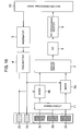
- FIG. 2 shows a configuration of the radar 1.
- the radar 1 includes an antenna section 1a including a transmission antenna 2 and the reception antennas 3a, 3b, and 3c; a transmitter 4, a modulator 5, a mixer 6, an analog circuit 7, an analog-to-digital (A/D) converter 8, an FFT (Fast Fourier Transform) processing section 9, a signal processing section 10, and a hybrid circuit 11.
- A/D analog-to-digital
- FFT Fast Fourier Transform
- the transmitter 4 outputs a high-frequency signal in a millimeter wave band according to a modulated signal from the modulator 5.
- the high-frequency signal is radiated as a transmission signal from the transmission antenna 2.
- the transmission signal is reflected by an object in an area of the radiation and the reflected signal is received by the reception antennas 3a, 3b, and 3c.
- the hybrid circuit 11 first conducts an addition and a subtraction using received signals respectively of the reception antennas 3a and 3b to create a sum signal (SumAB) and a difference signal (DiffAB). Similarly, the hybrid circuit 11 conducts an addition and a subtraction using received signals respectively of the reception antennas 3b and 3c to create a sum signal (SumBC) and a difference signal (DiffBC).
- the mixer 6 conducts a frequency conversion using the sum and difference signals and the signals received by the reception antennas 3a, 3b, and 3c.
- the mixer 6 is also supplied with the transmission signal from the transmitter 4 and mixes the transmission signal with the received signal to create a low-frequency signal and outputs the signal to the analog circuit 7.
- a difference (Doppler shift) between the frequency of the transmission signal and that of the received signal due to existence of the object is reflected in the low-frequency signal.
- the analog circuit 7 amplifies the signal inputted thereto and outputs the resultant signal to the A/D converter 8.
- the converter 8 converts the input signal into a digital signal to supply the signal to the FFT processing section 9.
- the section 9 measures the frequency spectrum of the signal through a fast Fourier transform (FFT) to obtain information of amplitude and phases and sends the information to the signal processing section 10.
- the section 10 calculates distance (range) and a rate using data in the frequency zone obtained by the FFT processing section 9 and outputs a measured distance (range) value and a measured rate value.
- FFT fast Fourier transform
- the two-frequency CW method is a method in which the transmission signal has two frequencies, not a single frequency, and in which the frequencies are alternately changed at a predetermined interval of time.
- the two-frequency CW method is a method using this characteristic in which by changing the frequency of the transmission signal, the distance (range) to the object is measured using phase information of received signals for the respective frequencies.
- a modulated signal is inputted to the transmitter 4 to transmit signals by changing the frequency between f1 and f2 at an interval of time as shown in FIG. 4A.
- a vehicle 12b exists, for example, at a position shown in FIG. 3, a radio wave sent from the transmission antenna 2 is reflected by the vehicle 12b before the radar.
- the reflected signals are then received by the reception antennas 3b and 3c.
- the antenna 3a does not receive the reflected signal from the vehicle 12b.
- the mixer 6 mixes the received signals of the reception antennas 3b and 3c with a signal from the transmitter 4 to obtain a beat signal.
- fc is a transmission frequency
- R' is a rate
- c is the speed of light.
- the analog circuit section 7 separates and demodulates a received signal for each transmission frequency, and then the A/D converter 8 conducts an A/D conversion for the received signal of each transmission frequency.
- the FFT processing section 9 executes fast Fourier transform processing for digital sample data obtained through the A/D conversion to attain a frequency spectrum in the overall frequency band of the received beat signal.
- power spectra of peak signals respectively of the transmission frequencies f1 and f2 are measured as shown in FIG. 4B using the peak signal obtained as a result of the FFT processing.
- FIG. 3 shows a schematic diagram showing a state of a radar mounted on a vehicle in which the radar is viewed from an upper side of the vehicle.
- the reception antennas 3a, 3b, and 3c are arranged as below. That is, a central line of the reception beam 3A of the reception antenna 3a is installed with an offset toward the left-hand side relative to a central line of the reception beam 3B of the reception antenna 3b and a central line of the reception beam 3C of the reception antenna 3c is installed with an offset toward the right-hand side relative to the central line of the reception beam 3B of the reception antenna 3b.
- the reception beam 3A is a range to cover a left-hand front area by an angle of ⁇ 1.
- ⁇ 1 is desirably equal to or more than 50°.
- the reception beam 3C is a range to cover a right-hand front area by an angle of ⁇ 2.
- ⁇ 2 is desirably equal to or more than 50°.
- the reception beam 3B is a range to cover an area by a wide angle of ⁇ 2 more than ⁇ 1 and ⁇ 2.
- ⁇ is desirably equal to or more than 100°.
- the reception antennas 3a, 3b, and 3c are set such that the reception beam 3A overlaps with the reception beam 3B by a predetermined angle Xa and the reception beam 3B overlaps with the reception beam 3C by a predetermined angle Xb.
- Xa and Xb are desirably equal to or more than 50%.
- an azimuth angle of a target can be attained using a difference between received signals from the two reception antennas.
- the overlapped areas are separated to be on the right-hand and left-hand sides, and hence the vehicles 12a and 12b can be separately detected. That is, the vehicle 12a is detected by the reception antennas 3a and 3b, but is not detected by the reception antenna c.
- the vehicle 12b is detected by the reception antennas 3b and 3c, but is not detected by the reception antenna a. Therefore, even when the vehicles 12a and 12b have the same rate and the same distance (range) with respect to the own vehicle, the vehicles can be separately detected. This suppresses the detection of the conventional radar in which the vehicles 12a and 12b are detected as one block or in which a wrong azimuth angle is detected.
- FIG. 3 shows examples of reception beam patterns when ⁇ is about 100° and ⁇ 1 and ⁇ 2 are about 60°.
- FIG. 5 shows received power patterns respectively of the reception antennas 3a, 3b, and 3c.
- Each reception beam has a range implemented by the configuration of the antennas in which reception patterns of FIG. 5 overlap with each other by a predetermined value X1 or X2 in the angular direction.
- FIG. 5 shows an example in which X1 and X2 are set such that the azimuth angle satisfied by each of the reception patterns 3Xa and 3Xc overlaps with 50% of the reception pattern 3Xb.
- the overlap X3 is desirably small for the reception patterns 3Xa and 3Xc, and it is desirable that the reception patterns are set such that received power Y for the overlapped area X3 is, for example, 20 decibel (dB) or less.
- FIG. 6 shows patterns of the sum signal (SumBC) and the difference signal (DiffBC) of the received signals in the right-hand range of the center of the radar. Since the patterns of the sum and difference signals are fixed as shown in FIG. 6, when the target is on the right-hand side viewed from the antenna attaching position like the vehicle 12b, the sum signal (SumBC) and the difference signal (DiffBC) of the signals inputted to the reception antennas 3b and 3c are calculated to identify the azimuth angle ⁇ using a ratio in power between the received signals.
- the sum signal (SumAB) and the difference signal (DiffAB) of the signals inputted to the reception antennas 3a and 3b are calculated to identify the azimuth angle ⁇ using a ratio in power between the received signals.
- a wide range detection is possible by one radar. Not only the distance (range) and the rate of the detection object, but also the azimuth can be detected. This consequently improves object detection precision. Additionally, an object on the left-hand side and an object on the right-hand side are separately detected according to the present embodiment. Therefore, in a scene in which one vehicle is at halt on the right-hand side and another vehicle is at halt on the left-hand side before the own vehicle, the vehicles on both sides can be separately detected. Since a moving section as in the scan radar is not required according to the present embodiment, the radar can be further reduced in size.
- the driver ordinarily considers that the control of distance (range) between cars and the control for crash mitigation do not operate, and hence determines that the own vehicle can pass through the place without any trouble. Therefore, the driver does not predict that the own vehicle is braked. In consequence, if the control of distance (range) between cars or the control for crash mitigation operates, the driver have an uncomfortable feeling as well as the driver is set to a dangerous situation in some cases.
- the own vehicle can path through the space between the vehicles.
- the speed of the own vehicle is more than a predetermined speed, it is also possible to conduct control of reducing the speed to a predetermined speed to pass through the space. Therefore, by using the radar of the present invention, there can be implemented vehicle travelling control satisfying expectation of the driver.
- the radar can be favorably used as a device to detect objects for crash mitigation when another car is entering a space before the own vehicle or when the own vehicle suddenly meets another vehicle.
- the distance (range) and the rate are calculated in association with the angle detecting function in the above method.
- the distance (range) and the rate of the target are calculated.
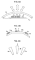
- FIG. 9 is a diagram showing a configuration of the antenna section viewed from a lateral direction with respect to the transmission and reception surfaces of the antenna.
- the radar is attached onto a vehicle such that the side shown in FIG. 9 is an upper side and the transmission and reception surfaces of the antenna face the front side of the vehicle.
- FIG. 9A shows an example in which planar antennas are adopted as transmission and reception antennas.
- One transmission antenna 2 and three reception antennas 3a, 3b, and 3c are horizontally arranged to be installed onto a holding member 14 with directivity such that reception beams of the reception antennas 3a and 3c respectively have an offset on the right and left sides with respect to a reception beam of the reception antenna 3b. Since width of each of the transmission and reception beams is almost inversely proportional to horizontal width of the associated antenna, in order to implement the reception beam pattern shown, for example, in FIG. 3, it is required that the horizontal width of each of the reception antennas 3a and 3c is larger than that of the reception antenna 3b.
- each of the reception antennas 3a, 3b, and 3c includes an array of small antennas such that received power of each small antenna is varied according to a reception beam pattern to be formed.
- each small antenna of the reception antenna 3c has, for example, the same received power as shown in FIG. 10B, a reception beam can be formed without any offset on the right and left sides.
- a reception beam can be formed without any offset on the right and left sides.
- the reception beam 3C has an offset toward the right-hand side viewed from the driver.
- the transmission antenna 2 is disposed on the right side and the reception antennas 3a, 3b, and 3c are arranged on the left side in the embodiment, it is also possible to dispose the transmission antenna 2 on the left side and the reception antennas 3a, 3b, and 3c on the right side.
- radio wave interference takes place.
- the radome 13 has a contour having a curvature and a radio wave absorber is disposed at positions at which radio wave interference possibly occurs.
- the positions are, for example, a position between the transmission antenna and the reception antenna and a position near an attaching section 14b between the radome 13 and the holding member 14.
- radio wave interference may occur at other positions, it is particularly probable that the interference takes place at the above positions. Therefore, occurrence of radio wave interference can be suppressed by disposing a radio wave absorber at these positions.
- the curvature of the radome 13 is desirably set such that the radio wave radiated from the transmission antenna 2 possibly enters a tangential plane of the radome with a right angle relative to the plane at the incident point.
- intensity of the radio wave reflected by the radome 13 can be reduced by appropriately selecting thickness and a material of the radome 13 in association with a wavelength of the radio wave.
- intensity of the reflected radio wave cannot be sufficiently reduced according to the thickness and the material of the radome 13.
- the radio wave radiated from the transmission antenna 2 can enter the radome 13 with an angle similar to a right angle, and hence the radio wave interference can be reduced.
- the curvature is shown only in the horizontal direction of the radome in FIG. 9A, the radio wave interference can be efficiently reduced in a configuration in which the radome has a curvature also in the vertical direction thereof.
- FIG. 9B shows an embodiment in which the holding member 14 includes three surfaces.
- the transmission antenna 2 and the reception antenna 3b are arranged on a central surface 14b
- the reception antenna 3a is arranged on a left surface 14a
- the reception antenna 3c is arranged on a right surface 14c to form patterns of the reception beams 3A, 3B, and 3C as shown in FIG. 3.
- FIG. 9C shows a case using horn antennas disposed to respectively face the left side, the front side, and the right side.
- the radar is simplified in the configuration and can be easily constructed.
- the radio wave interference between the respective antennas can also be easily prevented.
- FIG. 11 is a diagram showing layouts of the transmission antenna 2 and three reception antennas 3a, 3b, and 3c on the holding member 14 when the radar is mounted on the vehicle, the layouts being viewed from the front side of the vehicle.
- FIG. 11A shows an example using planar antennas as in FIG. 9A in which the transmission antenna 2 and the reception antennas 3a, 3b, and 3c are arranged in parallel to each other.
- FIG. 11B shows an example of a configuration of the antenna section as shown in FIG. 9A or 9B in which the transmission antenna 2 and the reception antennas 3a, 3b, and 3c are vertically arranged.
- the configuration since three reception antennas 3a, 3b, and 3c are arranged in parallel to each other, wiring is efficiently conducted in consideration of connection to the hybrid circuit 11.
- the central line of the transmission beam of the transmission antenna 2 is substantially aligned with that of the reception beam 3B of the central reception antenna 3b and the offset is not required to be considered, and hence processing of computation can be simplified.
- FIG. 11C shows an example in which the transmission antenna 2 and the central reception antenna 3b are arranged in parallel to each other and the reception antennas 3a and 3c are arranged on both sides.
- the transmission antenna 2 and the reception antenna 3b have a transmission beam and a reception beam with a wider angle than the angles of the reception beams of the reception antennas 3a and 3c.
- the horizontal width of the antenna is substantially inversely proportional to the angle of the beam of the antenna, the horizontal width of each of the transmission antenna 2 and the reception antenna 3b is ordinarily narrower than that of each of the reception antennas 3a and 3c. Therefore, by arranging the transmission antenna 2 and the reception antenna 3b having the narrower horizontal width side by side in the central position as shown in FIG. 11C, the overall antenna size can be reduced.
- FIG. 13 shows results of the FFT processing executed for signals received by one reception antenna.
- a peak signal is detected for each FFT signal.
- the peak signal is a signal of which the value of received power exceeds a threshold value (noise level) in FIG. 13.
- a threshold value noise level
- step 17 If the Doppler frequency of the signal received by the antenna 3a matches that of the signal received by the antenna 3b (i.e., the difference with respect to fp is substantially equal to or less than a predetermined value), control goes to step 17. In this case, since the received signal of the same target is obtained by two reception antennas (3a and 3b), the sum and difference signals are calculated in step 17 and then angle detection is conducted in step 18. The rate and the distance (range) are calculated in step 19. Similarly, if the Doppler frequency of the signal received by the reception antenna 3b matches that of the signal received by the reception antenna 3c in step 16, control goes to step 20.
- step 20 since the received signal of the same target is obtained by two reception antennas (3b and 3c), the sum and difference signals are calculated in step 20 and then angle detection is conducted in step 21.
- the rate and the distance (range) are calculated in step 22. If the peak of the received signal is obtained only by one of the reception antennas 3a, 3b, and 3c in step 16, it is indicated in this case that the target is detected in an area in which the antenna beams do not overlap with each other in FIG. 1 and hence control goes to step 23.
- step 23 the rate and the distance (range) are calculated, but the azimuth angle is not calculated. In this operation, as an output value of the azimuth angle, a predetermined value indicating impossibility of angle detection is outputted.
- the particular value indicating impossibility of angle detection in this case is, for example, 100 [deg] which is not ordinarily outputted in consideration of the installed state of the reception antennas 3a, 3b, and 3c.
- the received signal from each reception antenna is first measured, it is possible to detect that the target exists on the right-hand side or the left-hand side.
- the distance (range) and the azimuth angle in the overall detection area as in this example at least five signal lines are required.
- the radar 1 includes two communication interfaces (I/F) connected to a bus 26.
- the communication interface 24 is an interface to output information of the distance (range), the rate, and the azimuth angle as information of a target detected by the radar 1.
- the communication interface 25 is an interface to output information from the self-diagnosis function of the radar 1.
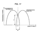
- FIG. 15 shows a configuration and patterns of transmission beams from the antenna section of the radar 1 in the embodiment.
- the antenna section includes two transmission antennas 2a and 2b and three reception antennas 3a, 3b, and 3c.
- the transmission antenna 2a has a beam pattern as indicated by a transmission beam 2A and sends radio waves in an area on the left-hand side viewed from the driver.
- the transmission antenna 2b has a beam pattern as indicated by a transmission beam 2B and sends radio waves in an area on the right-hand side viewed from the driver.
- the antenna section includes transmission antennas 2a and 2b and reception antennas 3a, 3b, and 3c.
- the transmission antennas 2a and 3b radiate high-frequency signals in a millimeter wave band sent from the transmitter 4 with a transmission frequency according to a modulated signal from a modulator 5.
- a radio wave signal reflected by an object in an area of the radiation is received by the reception antennas 3a, 3b, and 3c.
- the sum and difference signals are generated using the signals received by the reception antennas 3a and 3b and the sum and difference signals are generated using the signals received by the reception antennas 3b and 3c in a hybrid circuit 11.
- a frequency conversion is conducted for the resultant signals and the signals received by the respective reception antennas 3a, 3b, and 3c in mixers 6a and 6b.
- the mixers 6a and 6b are also supplied with signals from the transmitter 4.
- a low-frequency signal obtained by mixing the signals with the above signals is outputted to an analog circuit 7.
- the transmission beam 2A is a range to cover the left-side area with an angle ⁇ 1; concretely, ⁇ 1 is desirably equal to or more than 50°.
- the transmission beam 2B is a range to cover the right-side area with an angle ⁇ 2; concretely, ⁇ 2 is desirably equal to or more than 50°.
- FIG. 17 shows transmission power patterns respectively of the transmission antennas 2a and 2b.
- the transmission patterns 2Xa and 2Xb overlap with each other with a small overlapped area therebetween in FIG. 17. This can be implemented by the transmission patterns in which received power Y for an azimuth angle X4 of the overlapped area is equal to or less than 20 dB.
- FIG. 18 shows a scene in which a target such as a vehicle to be detected exists on the left-hand side and an object such as a wall which remarkably reflects radio waves exists on the right-hand side.
- a target such as a vehicle to be detected exists on the left-hand side
- an object such as a wall which remarkably reflects radio waves exists on the right-hand side.
- FIG. 18 shows a scene in which a target such as a vehicle to be detected exists on the left-hand side and an object such as a wall which remarkably reflects radio waves exists on the right-hand side.
- signal processing is executed by receiving a reflected wave from the target on the left side, it is possible to obtain a detection result of a target to be inherently detected.
- the result of the detection also indicates that an object exists on the right side, and hence there arises a problem of a multipath.
- mutually different transmission radio waves are respectively transmitted to the right-side and left-side areas as in the embodiment.
- a radar having a central frequency of, for example, 76.5 gigaherz (GHz) two kinds of transmission frequencies are transmitted such that the frequency difference between the transmission radio waves on the right and left sides is equal to or more than one gigaherz.
- the targets to be detected on the right and left sides can be detected using the respective transmission radio waves, and hence this is effective to solve the multipath problem.
Landscapes
- Engineering & Computer Science (AREA)
- Remote Sensing (AREA)
- Radar, Positioning & Navigation (AREA)
- Physics & Mathematics (AREA)
- Computer Networks & Wireless Communication (AREA)
- General Physics & Mathematics (AREA)
- Electromagnetism (AREA)
- Radar Systems Or Details Thereof (AREA)
Applications Claiming Priority (2)
| Application Number | Priority Date | Filing Date | Title |
|---|---|---|---|
| JP2003394872 | 2003-11-26 | ||
| JP2003394872A JP2005156337A (ja) | 2003-11-26 | 2003-11-26 | 車載用レーダ装置 |
Publications (2)
| Publication Number | Publication Date |
|---|---|
| EP1548458A2 true EP1548458A2 (de) | 2005-06-29 |
| EP1548458A3 EP1548458A3 (de) | 2007-01-10 |
Family
ID=34544851
Family Applications (1)
| Application Number | Title | Priority Date | Filing Date |
|---|---|---|---|
| EP04019181A Withdrawn EP1548458A3 (de) | 2003-11-26 | 2004-08-12 | In einem Kraftfahrzeug eingebautes Radar |
Country Status (3)
| Country | Link |
|---|---|
| US (1) | US20050110673A1 (de) |
| EP (1) | EP1548458A3 (de) |
| JP (1) | JP2005156337A (de) |
Cited By (11)
| Publication number | Priority date | Publication date | Assignee | Title |
|---|---|---|---|---|
| EP1837679A1 (de) * | 2006-03-23 | 2007-09-26 | Omron Corporation | Radargerät und Radarverfahren |
| WO2007147533A1 (de) * | 2006-06-21 | 2007-12-27 | Valeo Schalter Und Sensoren Gmbh | Kraftfahrzeug-radarsystem und verfahren zur bestimmung von geschwindikgeiten und enfernungen von objekten |
| EP1956389A1 (de) * | 2007-02-02 | 2008-08-13 | Omron Corporation | Zwei-Frequenz CW-Radar |
| EP2040336A1 (de) * | 2007-08-03 | 2009-03-25 | InnoSenT GmbH | Radarsensor |
| EP2068172A2 (de) | 2007-12-04 | 2009-06-10 | Robert Bosch GmbH | Adaptives Platzieren von Nullstellen im Monopuls-Differenz-Antennendiagramm zur verbesserten Winkelauflösung an Objektorten |
| WO2010000251A3 (de) * | 2008-07-02 | 2010-02-25 | Adc Automotive Distance Control Systems Gmbh | Radarsystem mit überlappenden sende- und empfangsantennen |
| WO2012113366A1 (de) * | 2011-02-23 | 2012-08-30 | S.M.S. Smart Microwave Sensors Gmbh | Verfahren und radar-sensoranordnung zur detektion von ort und geschwindigkeit von objekten relativ zu einem messort, insbesondere fahrzeug |
| EP2944977A1 (de) * | 2014-05-15 | 2015-11-18 | Delphi Technologies, Inc. | Radarsystem mit verbesserter mehrfachzielunterscheidung |
| WO2016177495A1 (en) * | 2015-05-01 | 2016-11-10 | Robert Bosch Gmbh | Detection system for mounting on a corner of a vehicle |
| US10823836B2 (en) | 2015-11-19 | 2020-11-03 | Conti Temic Microelectronic Gmbh | Radar system having interleaved serial transmitting and parallel receiving |
| US20230030172A1 (en) * | 2021-07-30 | 2023-02-02 | Argo AI, LLC | Method, System, and Computer Program Product for Resolving Level Ambiguity for Radar Systems of Autonomous Vehicles |
Families Citing this family (23)
| Publication number | Priority date | Publication date | Assignee | Title |
|---|---|---|---|---|
| US7136753B2 (en) * | 2002-12-05 | 2006-11-14 | Denso Corporation | Object recognition apparatus for vehicle, inter-vehicle control apparatus, and distance measurement apparatus |
| US7612706B2 (en) * | 2004-07-16 | 2009-11-03 | Fujitsu Ten Limited | Monopulse radar apparatus and antenna switch |
| EP1729146A1 (de) * | 2005-06-01 | 2006-12-06 | BAE SYSTEMS (Defence Systems) Limited | Funkpeilantennensystem |
| JP4337887B2 (ja) * | 2007-02-21 | 2009-09-30 | 株式会社デンソー | 車載ミリ波レーダ装置 |
| JP4766402B2 (ja) * | 2008-10-21 | 2011-09-07 | トヨタ自動車株式会社 | レーダ装置 |
| EP2629113B1 (de) | 2009-04-06 | 2017-04-26 | Conti Temic microelectronic GmbH | Radarsystem mit anordnungen und verfahren zur entkopplung von sende- und empfangssignalen sowie unterdrückung von störeinstrahlungen |
| JP5396475B2 (ja) * | 2009-07-31 | 2014-01-22 | 本田技研工業株式会社 | 車両用物体検知装置 |
| US8577550B2 (en) * | 2009-10-05 | 2013-11-05 | Ford Global Technologies, Llc | System for vehicle control to mitigate intersection collisions and method of using the same |
| KR101172240B1 (ko) * | 2010-05-18 | 2012-08-07 | 주식회사 만도 | 센서 및 얼라이먼트 조절 방법 |
| US8736484B2 (en) * | 2010-08-11 | 2014-05-27 | Lockheed Martin Corporation | Enhanced-resolution phased array radar |
| JP5696781B2 (ja) * | 2011-04-19 | 2015-04-08 | マツダ株式会社 | 車両用障害物検出装置 |
| KR20130065005A (ko) * | 2011-12-09 | 2013-06-19 | 주식회사 만도 | 레이더 장치 및 안테나 장치 |
| DE102011122346A1 (de) * | 2011-12-23 | 2013-06-27 | Valeo Schalter Und Sensoren Gmbh | Radareinrichtung für ein Kraftfahrzeug, Halter für ein Radargerät und Verfahren zum Herstellen eines Absorptionselements für ein Radargerät |
| CA2893194C (en) * | 2014-07-30 | 2018-06-19 | Shigeru OHSUGI | Transporter vehicle and transporter vehicle control method |
| JP6415386B2 (ja) * | 2015-05-28 | 2018-10-31 | 三菱電機株式会社 | 測角装置、レーダ装置、及び測角方法 |
| JP6266188B1 (ja) * | 2016-05-20 | 2018-01-24 | 三菱電機株式会社 | 気象レーダ装置 |
| KR102314336B1 (ko) * | 2017-09-14 | 2021-10-19 | 주식회사 만도모빌리티솔루션즈 | 차량용 레이더 장치 및 그의 각도 추정 방법 |
| JP6844525B2 (ja) * | 2017-12-26 | 2021-03-17 | 株式会社デンソー | アンテナ装置 |
| KR102132774B1 (ko) * | 2018-01-10 | 2020-07-21 | 주식회사 만도 | 레이더 제어 장치 및 그 방법 |
| CN113412433A (zh) * | 2019-01-31 | 2021-09-17 | 三菱电机株式会社 | 测角装置、测角方法及车载装置 |
| US11226397B2 (en) * | 2019-08-06 | 2022-01-18 | Waymo Llc | Slanted radomes |
| US11385325B2 (en) * | 2019-08-07 | 2022-07-12 | Waymo Llc | Corrugated radomes |
| US12362470B1 (en) | 2021-11-18 | 2025-07-15 | Waymo Llc | Systems, methods, and apparatus for determining characteristics of a radome |
Citations (1)
| Publication number | Priority date | Publication date | Assignee | Title |
|---|---|---|---|---|
| EP0805360A2 (de) * | 1996-05-02 | 1997-11-05 | Honda Giken Kogyo Kabushiki Kaisha | Mehrstrahl-Radarsystem |
Family Cites Families (45)
| Publication number | Priority date | Publication date | Assignee | Title |
|---|---|---|---|---|
| DE2553302A1 (de) * | 1975-11-27 | 1977-06-02 | Standard Elektrik Lorenz Ag | Rueckstrahlortungsgeraet, insbesondere fuer kraftfahrzeuge |
| JPS6045377B2 (ja) * | 1976-08-03 | 1985-10-09 | 日産自動車株式会社 | 衝突防止装置 |
| US4308536A (en) * | 1979-02-26 | 1981-12-29 | Collision Avoidance Systems | Anti-collision vehicular radar system |
| IT1222297B (it) * | 1988-01-18 | 1990-09-05 | Paolo Alberto Paoletti | Radar antinebbia per autoveicoli |
| GB9102585D0 (en) * | 1991-02-06 | 1991-03-27 | Marconi Gec Ltd | Radar system |
| JP2567332B2 (ja) * | 1993-02-17 | 1996-12-25 | 本田技研工業株式会社 | 時分割型レーダシステム |
| US5402129A (en) * | 1993-08-04 | 1995-03-28 | Vorad Safety Systems, Inc. | Monopulse azimuth radar system for automotive vehicle tracking |
| JP2768439B2 (ja) * | 1994-11-08 | 1998-06-25 | 本田技研工業株式会社 | Fm−cw方式マルチビームレーダー装置 |
| US5767793A (en) * | 1995-04-21 | 1998-06-16 | Trw Inc. | Compact vehicle based rear and side obstacle detection system including multiple antennae |
| JP4082725B2 (ja) * | 1995-07-01 | 2008-04-30 | ローベルト ボツシユ ゲゼルシヤフト ミツト ベシユレンクテル ハフツング | モノスタチックfmcwレーダセンサ |
| JP3656290B2 (ja) * | 1995-09-01 | 2005-06-08 | 株式会社デンソー | モノパルスレーダ装置 |
| JPH09191213A (ja) * | 1995-11-07 | 1997-07-22 | Denso Corp | 開口面アンテナ |
| JP3663702B2 (ja) * | 1995-12-05 | 2005-06-22 | 株式会社デンソー | 平面アレーアンテナ及び位相モノパルスレーダ装置 |
| EP0809811B1 (de) * | 1995-12-19 | 2001-07-11 | Siemens Schweiz AG | Verfahren und amplituden- oder phasen-monopulsradargerät zur ortung von flugobjekten |
| US5959571A (en) * | 1996-04-22 | 1999-09-28 | The Furukawa Electric Co., Ltd. | Radar device |
| JP3012805B2 (ja) * | 1996-05-09 | 2000-02-28 | 本田技研工業株式会社 | Fmレーダ装置 |
| US5781157A (en) * | 1996-08-05 | 1998-07-14 | Mcdonnell Douglas Corporation | Multiple beam radar system with enhanced sidelobe supression |
| DE19648203C2 (de) * | 1996-11-21 | 1999-06-10 | Bosch Gmbh Robert | Mehrstrahliges Kraftfahrzeug-Radarsystem |
| JP3799724B2 (ja) * | 1997-03-27 | 2006-07-19 | 株式会社デンソー | 開口面アンテナ及びレーダ装置 |
| JPH1116099A (ja) * | 1997-06-27 | 1999-01-22 | Hitachi Ltd | 自動車走行支援装置 |
| US5929802A (en) * | 1997-11-21 | 1999-07-27 | Raytheon Company | Automotive forward looking sensor application |
| JP4238375B2 (ja) * | 1997-12-25 | 2009-03-18 | 株式会社豊田中央研究所 | レーダ装置 |
| JP3942722B2 (ja) * | 1998-02-16 | 2007-07-11 | 本田技研工業株式会社 | 車載レーダ装置 |
| JPH11271430A (ja) * | 1998-03-25 | 1999-10-08 | Toyota Central Res & Dev Lab Inc | 自動車レーダ装置 |
| DE19829762A1 (de) * | 1998-07-03 | 2000-01-13 | Adc Automotive Dist Control | Verfahren zum Betrieb eines Radarsystems |
| JP2000028704A (ja) * | 1998-07-07 | 2000-01-28 | Nec Corp | レーダ装置 |
| JP3622565B2 (ja) * | 1999-03-31 | 2005-02-23 | 株式会社デンソー | レーダ装置 |
| JP4258941B2 (ja) * | 1999-06-03 | 2009-04-30 | 株式会社デンソー | レーダ装置 |
| JP3393204B2 (ja) * | 1999-10-06 | 2003-04-07 | 株式会社ホンダエレシス | マルチビームレーダ装置 |
| JP3411866B2 (ja) * | 1999-10-25 | 2003-06-03 | 株式会社日立製作所 | ミリ波レーダ装置 |
| EP1253441B1 (de) * | 2000-01-28 | 2010-04-07 | Hitachi, Ltd. | Entfernungsmessgerät |
| JP2001296352A (ja) * | 2000-04-12 | 2001-10-26 | Omron Corp | 対象物検出装置 |
| JP2002131425A (ja) * | 2000-10-26 | 2002-05-09 | Matsushita Electric Works Ltd | レーダ装置、車載用レーダ装置並びに衝突防止システム |
| EP1391748A4 (de) * | 2001-05-30 | 2007-01-31 | Hitachi Ltd | Radareinrichtung |
| JP2003066139A (ja) * | 2001-08-27 | 2003-03-05 | Hitachi Ltd | レーダ装置 |
| US6750810B2 (en) * | 2001-12-18 | 2004-06-15 | Hitachi, Ltd. | Monopulse radar system |
| DE60205711T2 (de) * | 2001-12-18 | 2006-05-18 | Hitachi, Ltd. | Monopuls Radar mit Einstellung der Strahlaufweitung |
| US6664918B2 (en) * | 2002-01-09 | 2003-12-16 | Mia-Com, Inc. | Method and apparatus for identifying complex objects based on range readings from multiple sensors |
| US7295154B2 (en) * | 2002-01-17 | 2007-11-13 | The Ohio State University | Vehicle obstacle warning radar |
| JP2003248054A (ja) * | 2002-02-27 | 2003-09-05 | Hitachi Ltd | モノパルスレーダ装置 |
| JP3688255B2 (ja) * | 2002-09-20 | 2005-08-24 | 株式会社日立製作所 | 車載用電波レーダ装置及びその信号処理方法 |
| DE10261027A1 (de) * | 2002-12-24 | 2004-07-08 | Robert Bosch Gmbh | Winkelauflösendes Antennensystem |
| JP4093109B2 (ja) * | 2003-05-15 | 2008-06-04 | 株式会社デンソー | 車両用レーダ装置 |
| US7586436B2 (en) * | 2003-09-11 | 2009-09-08 | Mitsubishi Denki Kabushiki Kaisha | Radar device |
| EP1666915A1 (de) * | 2003-09-11 | 2006-06-07 | Mitsubishi Denki Kabushiki Kaisha | Radareinrichtung |
-
2003
- 2003-11-26 JP JP2003394872A patent/JP2005156337A/ja active Pending
-
2004
- 2004-08-12 EP EP04019181A patent/EP1548458A3/de not_active Withdrawn
- 2004-08-19 US US10/921,176 patent/US20050110673A1/en not_active Abandoned
Patent Citations (1)
| Publication number | Priority date | Publication date | Assignee | Title |
|---|---|---|---|---|
| EP0805360A2 (de) * | 1996-05-02 | 1997-11-05 | Honda Giken Kogyo Kabushiki Kaisha | Mehrstrahl-Radarsystem |
Cited By (24)
| Publication number | Priority date | Publication date | Assignee | Title |
|---|---|---|---|---|
| EP1837679A1 (de) * | 2006-03-23 | 2007-09-26 | Omron Corporation | Radargerät und Radarverfahren |
| US7548182B2 (en) | 2006-03-23 | 2009-06-16 | Omron Corporation | Radar device and radar method |
| CN101042435B (zh) * | 2006-03-23 | 2011-03-23 | 欧姆龙汽车电子株式会社 | 单脉冲式雷达装置 |
| WO2007147533A1 (de) * | 2006-06-21 | 2007-12-27 | Valeo Schalter Und Sensoren Gmbh | Kraftfahrzeug-radarsystem und verfahren zur bestimmung von geschwindikgeiten und enfernungen von objekten |
| US8704704B2 (en) | 2006-06-21 | 2014-04-22 | Valeo Schalter Und Sensoren Gmbh | Motor vehicle radar system, and method for determining speeds and distances of objects |
| EP1956389A1 (de) * | 2007-02-02 | 2008-08-13 | Omron Corporation | Zwei-Frequenz CW-Radar |
| EP2040336A1 (de) * | 2007-08-03 | 2009-03-25 | InnoSenT GmbH | Radarsensor |
| EP2068172A2 (de) | 2007-12-04 | 2009-06-10 | Robert Bosch GmbH | Adaptives Platzieren von Nullstellen im Monopuls-Differenz-Antennendiagramm zur verbesserten Winkelauflösung an Objektorten |
| EP2068172A3 (de) * | 2007-12-04 | 2010-03-24 | Robert Bosch GmbH | Adaptives Platzieren von Nullstellen im Monopuls-Differenz-Antennendiagramm zur verbesserten Winkelauflösung an Objektorten |
| US8035548B2 (en) | 2007-12-04 | 2011-10-11 | Robert Bosch Gmbh | Evaluation method, particularly for a driver assistance system of a motor vehicle, for object detection using a radar sensor |
| US8436763B2 (en) | 2008-07-02 | 2013-05-07 | Adc Automotive Distance Control Systems Gmbh | Radar system comprising overlapping transmitter and receiver antennas |
| US8390507B2 (en) | 2008-07-02 | 2013-03-05 | Adc Automotive Distance Control Systems Gmbh | Radar system with elevation measuring capability |
| US8593333B2 (en) | 2008-07-02 | 2013-11-26 | Adc Automotive Distance Control Systems Gmbh | Radar sensor with frontal and lateral emission |
| US8665137B2 (en) | 2008-07-02 | 2014-03-04 | Adc Automotive Distance Control Systems Gmbh | Radar system with improved angle formation |
| WO2010000251A3 (de) * | 2008-07-02 | 2010-02-25 | Adc Automotive Distance Control Systems Gmbh | Radarsystem mit überlappenden sende- und empfangsantennen |
| WO2012113366A1 (de) * | 2011-02-23 | 2012-08-30 | S.M.S. Smart Microwave Sensors Gmbh | Verfahren und radar-sensoranordnung zur detektion von ort und geschwindigkeit von objekten relativ zu einem messort, insbesondere fahrzeug |
| CN105093213A (zh) * | 2014-05-15 | 2015-11-25 | 德尔福技术有限公司 | 具有改进的多目标区分的雷达系统 |
| EP2944977A1 (de) * | 2014-05-15 | 2015-11-18 | Delphi Technologies, Inc. | Radarsystem mit verbesserter mehrfachzielunterscheidung |
| US9310468B2 (en) | 2014-05-15 | 2016-04-12 | Delphi Technologies, Inc. | Radar system with improved multi-target discrimination |
| CN105093213B (zh) * | 2014-05-15 | 2019-07-02 | 安波福技术有限公司 | 具有改进的多目标区分的雷达系统 |
| WO2016177495A1 (en) * | 2015-05-01 | 2016-11-10 | Robert Bosch Gmbh | Detection system for mounting on a corner of a vehicle |
| US10823836B2 (en) | 2015-11-19 | 2020-11-03 | Conti Temic Microelectronic Gmbh | Radar system having interleaved serial transmitting and parallel receiving |
| US20230030172A1 (en) * | 2021-07-30 | 2023-02-02 | Argo AI, LLC | Method, System, and Computer Program Product for Resolving Level Ambiguity for Radar Systems of Autonomous Vehicles |
| US11807271B2 (en) * | 2021-07-30 | 2023-11-07 | Ford Global Technologies, Llc | Method, system, and computer program product for resolving level ambiguity for radar systems of autonomous vehicles |
Also Published As
| Publication number | Publication date |
|---|---|
| JP2005156337A (ja) | 2005-06-16 |
| US20050110673A1 (en) | 2005-05-26 |
| EP1548458A3 (de) | 2007-01-10 |
Similar Documents
| Publication | Publication Date | Title |
|---|---|---|
| EP1548458A2 (de) | In einem Kraftfahrzeug eingebautes Radar | |
| JP4045041B2 (ja) | レーダ装置及びレーダ装置の異常検出方法 | |
| JP4115638B2 (ja) | 物体認識装置 | |
| JP4007498B2 (ja) | 車載用レーダ装置 | |
| CN112654888A (zh) | 电子设备、电子设备的控制方法、以及电子设备的控制程序 | |
| US20110084872A1 (en) | Signal processing apparatus and radar apparatus | |
| US11709261B2 (en) | Radar device for vehicle, controlling method of radar device and radar system for vehicle | |
| US20080258964A1 (en) | Radar System | |
| US20100075618A1 (en) | Signal processing apparatus and radar apparatus | |
| JP4088583B2 (ja) | レーダ装置 | |
| JP2021165758A (ja) | 電子機器、電子機器の制御方法、及び電子機器の制御プログラム | |
| WO2021019934A1 (ja) | 電子機器、電子機器の制御方法、及びプログラム | |
| US7091900B2 (en) | Radar | |
| WO2005066656A1 (ja) | 車載レーダ装置およびその信号処理方法 | |
| CN117616306A (zh) | 电子设备、电子设备的控制方法以及程序 | |
| CN116529627A (zh) | 电子设备、电子设备的控制方法、以及程序 | |
| JP2020012702A (ja) | 車両用レーダ装置 | |
| JP2000206234A (ja) | Fm―cwレ―ダ装置 | |
| JP3577237B2 (ja) | 車両用レーダ装置 | |
| JP3723804B2 (ja) | 車載用レーダ装置 | |
| WO2020241235A1 (ja) | 電子機器、電子機器の制御方法、及びプログラム | |
| JPH11110685A (ja) | 交通管制支援システム | |
| JP3496606B2 (ja) | レーダ装置 | |
| WO2023032620A1 (ja) | 電子機器、電子機器の制御方法、及びプログラム | |
| CN117063083A (zh) | 电子设备 |
Legal Events
| Date | Code | Title | Description |
|---|---|---|---|
| PUAI | Public reference made under article 153(3) epc to a published international application that has entered the european phase |
Free format text: ORIGINAL CODE: 0009012 |
|
| AK | Designated contracting states |
Kind code of ref document: A2 Designated state(s): AT BE BG CH CY CZ DE DK EE ES FI FR GB GR HU IE IT LI LU MC NL PL PT RO SE SI SK TR |
|
| AX | Request for extension of the european patent |
Extension state: AL HR LT LV MK |
|
| PUAL | Search report despatched |
Free format text: ORIGINAL CODE: 0009013 |
|
| AK | Designated contracting states |
Kind code of ref document: A3 Designated state(s): AT BE BG CH CY CZ DE DK EE ES FI FR GB GR HU IE IT LI LU MC NL PL PT RO SE SI SK TR |
|
| AX | Request for extension of the european patent |
Extension state: AL HR LT LV MK |
|
| 17P | Request for examination filed |
Effective date: 20070710 |
|
| AKX | Designation fees paid |
Designated state(s): DE FR |
|
| 17Q | First examination report despatched |
Effective date: 20070816 |
|
| STAA | Information on the status of an ep patent application or granted ep patent |
Free format text: STATUS: THE APPLICATION IS DEEMED TO BE WITHDRAWN |
|
| 18D | Application deemed to be withdrawn |
Effective date: 20110301 |