EP1548313B1 - Dispositif de transmission de couple - Google Patents
Dispositif de transmission de couple Download PDFInfo
- Publication number
- EP1548313B1 EP1548313B1 EP04029777.2A EP04029777A EP1548313B1 EP 1548313 B1 EP1548313 B1 EP 1548313B1 EP 04029777 A EP04029777 A EP 04029777A EP 1548313 B1 EP1548313 B1 EP 1548313B1
- Authority
- EP
- European Patent Office
- Prior art keywords
- transmission device
- torque transmission
- friction
- actuating
- clutch
- Prior art date
- Legal status (The legal status is an assumption and is not a legal conclusion. Google has not performed a legal analysis and makes no representation as to the accuracy of the status listed.)
- Active
Links
- 230000005540 biological transmission Effects 0.000 title claims description 162
- 230000008878 coupling Effects 0.000 claims description 22
- 238000010168 coupling process Methods 0.000 claims description 22
- 238000005859 coupling reaction Methods 0.000 claims description 22
- 239000002826 coolant Substances 0.000 claims description 21
- 238000001816 cooling Methods 0.000 claims description 13
- 238000002485 combustion reaction Methods 0.000 claims description 10
- 230000033001 locomotion Effects 0.000 claims description 9
- 238000000034 method Methods 0.000 claims description 3
- 230000000295 complement effect Effects 0.000 claims description 2
- 230000001419 dependent effect Effects 0.000 claims description 2
- 230000001105 regulatory effect Effects 0.000 claims description 2
- 238000007789 sealing Methods 0.000 claims description 2
- 238000011144 upstream manufacturing Methods 0.000 claims 1
- 230000009977 dual effect Effects 0.000 description 27
- 238000004146 energy storage Methods 0.000 description 19
- 239000002184 metal Substances 0.000 description 9
- 238000006073 displacement reaction Methods 0.000 description 5
- 230000000694 effects Effects 0.000 description 3
- 230000001276 controlling effect Effects 0.000 description 2
- 238000010586 diagram Methods 0.000 description 2
- 238000007373 indentation Methods 0.000 description 2
- 239000000314 lubricant Substances 0.000 description 2
- 238000004519 manufacturing process Methods 0.000 description 2
- 238000003860 storage Methods 0.000 description 2
- 241001295925 Gegenes Species 0.000 description 1
- 229910000639 Spring steel Inorganic materials 0.000 description 1
- 230000009286 beneficial effect Effects 0.000 description 1
- 150000001875 compounds Chemical class 0.000 description 1
- 238000010276 construction Methods 0.000 description 1
- 238000013016 damping Methods 0.000 description 1
- 238000005265 energy consumption Methods 0.000 description 1
- 210000003746 feather Anatomy 0.000 description 1
- 239000002783 friction material Substances 0.000 description 1
- 238000009434 installation Methods 0.000 description 1
- 230000010354 integration Effects 0.000 description 1
- 238000005304 joining Methods 0.000 description 1
- 239000007788 liquid Substances 0.000 description 1
- 238000005461 lubrication Methods 0.000 description 1
- 238000007726 management method Methods 0.000 description 1
- 239000000463 material Substances 0.000 description 1
- 239000012528 membrane Substances 0.000 description 1
- 238000003825 pressing Methods 0.000 description 1
- 238000005086 pumping Methods 0.000 description 1
- 230000003014 reinforcing effect Effects 0.000 description 1
- 238000005096 rolling process Methods 0.000 description 1
- 239000011232 storage material Substances 0.000 description 1
- 210000002105 tongue Anatomy 0.000 description 1
Images


Classifications
-
- F—MECHANICAL ENGINEERING; LIGHTING; HEATING; WEAPONS; BLASTING
- F16—ENGINEERING ELEMENTS AND UNITS; GENERAL MEASURES FOR PRODUCING AND MAINTAINING EFFECTIVE FUNCTIONING OF MACHINES OR INSTALLATIONS; THERMAL INSULATION IN GENERAL
- F16D—COUPLINGS FOR TRANSMITTING ROTATION; CLUTCHES; BRAKES
- F16D48/00—External control of clutches
- F16D48/02—Control by fluid pressure
-
- F—MECHANICAL ENGINEERING; LIGHTING; HEATING; WEAPONS; BLASTING
- F16—ENGINEERING ELEMENTS AND UNITS; GENERAL MEASURES FOR PRODUCING AND MAINTAINING EFFECTIVE FUNCTIONING OF MACHINES OR INSTALLATIONS; THERMAL INSULATION IN GENERAL
- F16H—GEARING
- F16H45/00—Combinations of fluid gearings for conveying rotary motion with couplings or clutches
- F16H45/02—Combinations of fluid gearings for conveying rotary motion with couplings or clutches with mechanical clutches for bridging a fluid gearing of the hydrokinetic type
-
- F—MECHANICAL ENGINEERING; LIGHTING; HEATING; WEAPONS; BLASTING
- F16—ENGINEERING ELEMENTS AND UNITS; GENERAL MEASURES FOR PRODUCING AND MAINTAINING EFFECTIVE FUNCTIONING OF MACHINES OR INSTALLATIONS; THERMAL INSULATION IN GENERAL
- F16D—COUPLINGS FOR TRANSMITTING ROTATION; CLUTCHES; BRAKES
- F16D21/00—Systems comprising a plurality of actuated clutches
- F16D21/02—Systems comprising a plurality of actuated clutches for interconnecting three or more shafts or other transmission members in different ways
- F16D21/06—Systems comprising a plurality of actuated clutches for interconnecting three or more shafts or other transmission members in different ways at least two driving shafts or two driven shafts being concentric
-
- F—MECHANICAL ENGINEERING; LIGHTING; HEATING; WEAPONS; BLASTING
- F16—ENGINEERING ELEMENTS AND UNITS; GENERAL MEASURES FOR PRODUCING AND MAINTAINING EFFECTIVE FUNCTIONING OF MACHINES OR INSTALLATIONS; THERMAL INSULATION IN GENERAL
- F16D—COUPLINGS FOR TRANSMITTING ROTATION; CLUTCHES; BRAKES
- F16D25/00—Fluid-actuated clutches
- F16D25/08—Fluid-actuated clutches with fluid-actuated member not rotating with a clutching member
-
- F—MECHANICAL ENGINEERING; LIGHTING; HEATING; WEAPONS; BLASTING
- F16—ENGINEERING ELEMENTS AND UNITS; GENERAL MEASURES FOR PRODUCING AND MAINTAINING EFFECTIVE FUNCTIONING OF MACHINES OR INSTALLATIONS; THERMAL INSULATION IN GENERAL
- F16D—COUPLINGS FOR TRANSMITTING ROTATION; CLUTCHES; BRAKES
- F16D25/00—Fluid-actuated clutches
- F16D25/10—Clutch systems with a plurality of fluid-actuated clutches
-
- F—MECHANICAL ENGINEERING; LIGHTING; HEATING; WEAPONS; BLASTING
- F16—ENGINEERING ELEMENTS AND UNITS; GENERAL MEASURES FOR PRODUCING AND MAINTAINING EFFECTIVE FUNCTIONING OF MACHINES OR INSTALLATIONS; THERMAL INSULATION IN GENERAL
- F16D—COUPLINGS FOR TRANSMITTING ROTATION; CLUTCHES; BRAKES
- F16D25/00—Fluid-actuated clutches
- F16D25/12—Details not specific to one of the before-mentioned types
- F16D25/123—Details not specific to one of the before-mentioned types in view of cooling and lubrication
-
- F—MECHANICAL ENGINEERING; LIGHTING; HEATING; WEAPONS; BLASTING
- F16—ENGINEERING ELEMENTS AND UNITS; GENERAL MEASURES FOR PRODUCING AND MAINTAINING EFFECTIVE FUNCTIONING OF MACHINES OR INSTALLATIONS; THERMAL INSULATION IN GENERAL
- F16D—COUPLINGS FOR TRANSMITTING ROTATION; CLUTCHES; BRAKES
- F16D48/00—External control of clutches
- F16D48/02—Control by fluid pressure
- F16D48/0206—Control by fluid pressure in a system with a plurality of fluid-actuated clutches
-
- F—MECHANICAL ENGINEERING; LIGHTING; HEATING; WEAPONS; BLASTING
- F16—ENGINEERING ELEMENTS AND UNITS; GENERAL MEASURES FOR PRODUCING AND MAINTAINING EFFECTIVE FUNCTIONING OF MACHINES OR INSTALLATIONS; THERMAL INSULATION IN GENERAL
- F16F—SPRINGS; SHOCK-ABSORBERS; MEANS FOR DAMPING VIBRATION
- F16F15/00—Suppression of vibrations in systems; Means or arrangements for avoiding or reducing out-of-balance forces, e.g. due to motion
- F16F15/10—Suppression of vibrations in rotating systems by making use of members moving with the system
- F16F15/12—Suppression of vibrations in rotating systems by making use of members moving with the system using elastic members or friction-damping members, e.g. between a rotating shaft and a gyratory mass mounted thereon
- F16F15/131—Suppression of vibrations in rotating systems by making use of members moving with the system using elastic members or friction-damping members, e.g. between a rotating shaft and a gyratory mass mounted thereon the rotating system comprising two or more gyratory masses
- F16F15/13128—Suppression of vibrations in rotating systems by making use of members moving with the system using elastic members or friction-damping members, e.g. between a rotating shaft and a gyratory mass mounted thereon the rotating system comprising two or more gyratory masses the damping action being at least partially controlled by centrifugal masses
- F16F15/13135—Suppression of vibrations in rotating systems by making use of members moving with the system using elastic members or friction-damping members, e.g. between a rotating shaft and a gyratory mass mounted thereon the rotating system comprising two or more gyratory masses the damping action being at least partially controlled by centrifugal masses simple connection or disconnection of members at speed
-
- F—MECHANICAL ENGINEERING; LIGHTING; HEATING; WEAPONS; BLASTING
- F16—ENGINEERING ELEMENTS AND UNITS; GENERAL MEASURES FOR PRODUCING AND MAINTAINING EFFECTIVE FUNCTIONING OF MACHINES OR INSTALLATIONS; THERMAL INSULATION IN GENERAL
- F16D—COUPLINGS FOR TRANSMITTING ROTATION; CLUTCHES; BRAKES
- F16D21/00—Systems comprising a plurality of actuated clutches
- F16D21/02—Systems comprising a plurality of actuated clutches for interconnecting three or more shafts or other transmission members in different ways
- F16D21/06—Systems comprising a plurality of actuated clutches for interconnecting three or more shafts or other transmission members in different ways at least two driving shafts or two driven shafts being concentric
- F16D2021/0661—Hydraulically actuated multiple lamellae clutches
-
- F—MECHANICAL ENGINEERING; LIGHTING; HEATING; WEAPONS; BLASTING
- F16—ENGINEERING ELEMENTS AND UNITS; GENERAL MEASURES FOR PRODUCING AND MAINTAINING EFFECTIVE FUNCTIONING OF MACHINES OR INSTALLATIONS; THERMAL INSULATION IN GENERAL
- F16D—COUPLINGS FOR TRANSMITTING ROTATION; CLUTCHES; BRAKES
- F16D23/00—Details of mechanically-actuated clutches not specific for one distinct type
- F16D23/12—Mechanical clutch-actuating mechanisms arranged outside the clutch as such
- F16D2023/126—Actuation by rocker lever; Rocker levers therefor
-
- F—MECHANICAL ENGINEERING; LIGHTING; HEATING; WEAPONS; BLASTING
- F16—ENGINEERING ELEMENTS AND UNITS; GENERAL MEASURES FOR PRODUCING AND MAINTAINING EFFECTIVE FUNCTIONING OF MACHINES OR INSTALLATIONS; THERMAL INSULATION IN GENERAL
- F16D—COUPLINGS FOR TRANSMITTING ROTATION; CLUTCHES; BRAKES
- F16D48/00—External control of clutches
- F16D48/02—Control by fluid pressure
- F16D2048/0209—Control by fluid pressure characterised by fluid valves having control pistons, e.g. spools
-
- F—MECHANICAL ENGINEERING; LIGHTING; HEATING; WEAPONS; BLASTING
- F16—ENGINEERING ELEMENTS AND UNITS; GENERAL MEASURES FOR PRODUCING AND MAINTAINING EFFECTIVE FUNCTIONING OF MACHINES OR INSTALLATIONS; THERMAL INSULATION IN GENERAL
- F16D—COUPLINGS FOR TRANSMITTING ROTATION; CLUTCHES; BRAKES
- F16D48/00—External control of clutches
- F16D48/02—Control by fluid pressure
- F16D2048/0227—Source of pressure producing the clutch engagement or disengagement action within a circuit; Means for initiating command action in power assisted devices
- F16D2048/0233—Source of pressure producing the clutch engagement or disengagement action within a circuit; Means for initiating command action in power assisted devices by rotary pump actuation
- F16D2048/0236—Source of pressure producing the clutch engagement or disengagement action within a circuit; Means for initiating command action in power assisted devices by rotary pump actuation with multiple independent pumps, e.g. one per clutch, or for supplying fluid to different systems
-
- F—MECHANICAL ENGINEERING; LIGHTING; HEATING; WEAPONS; BLASTING
- F16—ENGINEERING ELEMENTS AND UNITS; GENERAL MEASURES FOR PRODUCING AND MAINTAINING EFFECTIVE FUNCTIONING OF MACHINES OR INSTALLATIONS; THERMAL INSULATION IN GENERAL
- F16D—COUPLINGS FOR TRANSMITTING ROTATION; CLUTCHES; BRAKES
- F16D2500/00—External control of clutches by electric or electronic means
- F16D2500/10—System to be controlled
- F16D2500/102—Actuator
- F16D2500/1021—Electrical type
- F16D2500/1023—Electric motor
- F16D2500/1024—Electric motor combined with hydraulic actuation
-
- F—MECHANICAL ENGINEERING; LIGHTING; HEATING; WEAPONS; BLASTING
- F16—ENGINEERING ELEMENTS AND UNITS; GENERAL MEASURES FOR PRODUCING AND MAINTAINING EFFECTIVE FUNCTIONING OF MACHINES OR INSTALLATIONS; THERMAL INSULATION IN GENERAL
- F16D—COUPLINGS FOR TRANSMITTING ROTATION; CLUTCHES; BRAKES
- F16D2500/00—External control of clutches by electric or electronic means
- F16D2500/10—System to be controlled
- F16D2500/104—Clutch
- F16D2500/10406—Clutch position
- F16D2500/10412—Transmission line of a vehicle
-
- F—MECHANICAL ENGINEERING; LIGHTING; HEATING; WEAPONS; BLASTING
- F16—ENGINEERING ELEMENTS AND UNITS; GENERAL MEASURES FOR PRODUCING AND MAINTAINING EFFECTIVE FUNCTIONING OF MACHINES OR INSTALLATIONS; THERMAL INSULATION IN GENERAL
- F16D—COUPLINGS FOR TRANSMITTING ROTATION; CLUTCHES; BRAKES
- F16D2500/00—External control of clutches by electric or electronic means
- F16D2500/10—System to be controlled
- F16D2500/104—Clutch
- F16D2500/10443—Clutch type
- F16D2500/1045—Friction clutch
Definitions
- the invention relates to a torque transmission device according to the preamble of claim 1, cf. DE-A-101 55 458 ,
- Dual clutch transmission with two transmission input shafts in which torque transmission devices are provided with a wet clutch for each transmission input shaft, wherein the wet clutches are hydrostatically actuated by means of corresponding piston units and the necessary pressure and possibly the pressure for cooling the clutches is generated by a pressure medium pump, if necessary, are known .
- Such pumps have high performance and consume a lot of energy.
- Between the pump and the piston units for establishing a pressure generated by the pump by means of a pressure medium for actuating the clutches rotary joints are provided with seals that seal between rotating and stationary components. Appropriate arrangements for the service life of these seals must be made.
- the object of the invention is to improve a torque transmission device and in particular a drive train to the effect that over the clutches of the two transmission input shafts with low energy consumption, a high power of the internal combustion engine can be transmitted while a simple and safe operation of the couplings at high transmission power and long life is possible.
- the production costs should be low and the production and assembly easy.
- At least one actuating device can be formed from a hydraulic transmitter unit, which can be actuated by means of an electric motor, consisting of a piston / cylinder unit, at least one hydraulic slave unit acting axially on the corresponding actuating bearing, consisting of a piston / cylinder unit, and a pressure medium line connecting a transmitter unit and slave unit.
- the slave unit may comprise a plurality of distributed over the circumference, arranged around at least one transmission input shaft subunits for acting on an actuating bearing, wherein for the application of both friction clutches both slave units distributed over the circumference subunits and they can be distributed over the circumference alternately and arranged on approximately the same circumference ,
- a Nehmeriki for a friction clutch from a pressurizable annular cylinder with axially displaceable annular piston, wherein two radially superposed Nehmerikien can each operate a friction clutch.
- Particularly advantageous may be an arrangement in which an outer annular piston is mounted directly axially displaceably sealing on a radially inner annular piston, wherein a separate pressure chamber is provided for both pistons, so that both clutches are independently operable.
- a piston / cylinder unit may be accommodated in the wall of the transmission and / or in the corresponding control part, or at least one piston may be introduced axially displaceably in a cylinder incorporated in the housing wall or the control part.
- Another exemplary embodiment may provide an electromechanical actuating device, wherein the application of at least one friction clutch by means of a substantially perpendicular to one of the transmission input shafts arranged electromotive rotary drive, wherein the rotary motion by means of a transmission in a translational movement along one of the transmission input shafts to act on the corresponding actuating bearing becomes.
- the application of at least one friction clutch by means of a substantially parallel or concentric to one of the transmission input shaft arranged electromotive rotary drive, wherein the rotational movement by means of a transmission in a translational along this transmission input shaft for acting the corresponding actuating bearing is converted. See, for example, the German patent disclosure DE 100 33 649 A1 called.
- friction clutches in special applications forcibly closed couplings can be disengaged using an axial force.
- these friction clutches are compressed clutches, that is, they are disengaged in the non-actuator state and are engaged by applying an axial force.
- a coolant flow for cooling at least one friction clutch by means of a pump.
- this pump in the range between a wall of the internal combustion engine and a wall of the Be arranged dual clutch transmission formed clutch bell.
- a coolant flow can be drawn in from an oil sump common to the transmission or from the transmission itself by means of the pump, or a separate oil circuit can be provided for the friction clutches. It may also be advantageous to design the pump in terms of its performance, in particular if no hydraulic pump is provided for controlling the transmission, in such a way that provision of the coolant flow is possible.
- the pump may be driven by the crankshaft or a component connected thereto.
- a coupling member in the vicinity of the transmission to be meshed with the pump is advantageously a component connected to the plate carrier which drives the ring gear of a radially further outwardly arranged internal gear pump by means of a gear wheel, wherein the internal gear pump is advantageously arranged in a space-saving area, for example between two gear wheels of the gearbox.
- the pump may be arranged on a housing wall of the transmission and indeed depending on the particular transmission concept in the space of the clutch bell or in the space of the transmission.
- An integration in the housing wall or in a common space with the transmission in a corresponding holder of the common space may be advantageous. It is understood that the pump can also be electrically powered.
- the drive by the crankshaft or an electric motor can be done by means of a gear connection, a belt drive, a chain drive or the like.
- the internal gear pump can be driven by means of a ring gear with an internal toothing, said internal toothing meshes with an external toothing of a sun gear and wherein for suction of the coolant, a suction cup is provided.
- the sun gear can be supported radially by means of its external toothing on a complementary segment of the suction cup, so that a separate storage of the sun gear can be omitted.
- the use of a gerotor pump may be advantageous. To minimize the energy requirement of the pump whose volume flow can be regulated by means of a suction throttling, wherein the suction throttling can be effected by means of a solenoid valve.
- a volume flow for example, up to a predetermined speed of the drive speed be proportional and kept at a constant value from a limit speed.
- a limitation of the coolant pressure to 5 bar, preferably 3 bar and a flow rate of not more than 36 l / min, preferably 24 l / min may be advantageous.
- an oil cooler can be connected between the pump and the friction units of the friction clutches.
- the coolant can escape through a corresponding opening in the chamber in the sump, and it may be advantageous to catch due to centrifugal force radially outwardly crowded coolant with a scoop mounted fixed to the housing and to lead into the sump.
- a scoop can be advantageously combined to form a unit with other functional elements, such as a slave unit.
- other pumps such as radial piston pumps, vane pumps, diaphragm pumps and the like may be advantageous.
- the entire clutch bell with cooling or pressure medium for example, commercially available ATF, be filled, also can be provided with a common space with the transmission space. It is particularly advantageous if in the clutch bell between a wall of the engine and a wall of the dual clutch transmission, a separate, liquid-tightly sealed against the clutch bell chamber is formed, in which at least the two friction clutches are added.
- This chamber can be formed by a component encompassing both friction clutches, for example a cup-shaped input part such as a plate carrier, wherein a part connected thereto can be mounted sealingly and rotatably on a stationary part such as a component of the actuating device or of the gear housing.
- a disk member may be fixedly connected to the transmission housing and may be rotatable and liquid-tight on a rotating member, such as on the hub of the input member.
- the arrangement according to the invention of the two friction clutches can be designed as a structural unit which is received directly on the crankshaft.
- the actuation system also be arranged directly on this unit and rotatably connected during assembly to the transmission to form a torque arm, wherein the individual clutch units are rotatably connected to the actuating system and stored.
- the clutch assembly may be received and supported on the crankshaft while the actuator is preassembled on the transmission housing.
- the coolant pump can be pre-assembled at the same time.
- An axial and / or radial bearing of this can be provided on the transmission housing.
- a two-mass flywheel arranged between crankshaft and input part of the two friction clutches can be provided on the torque transmission device.
- This dual mass flywheel may be integrated into the pressurized liquid filled chamber or disposed outside the chamber.
- the dual mass flywheel may further form part of the housing for the chamber and / or have a drive part for the pump.
- the inclusion of the dual mass flywheel on the crankshaft can be done by means of an axially flexible disc part, a so-called "flexplate". It is understood that the torque transfer device without dual mass flywheel can also be accommodated in this way on the crankshaft.
- the mass ratios of a dual clutch may be at least temporarily to make mutually opposite at least one circumferentially effective energy storage relatively rotatable, based on the flywheel drive side and output side masses, wherein the coupling can be done by means of a centrifugal force-dependent friction device.
- Particularly advantageous may be the use of a coupling in mass ratios in which the drive-side moment of inertia is greater than the output side, for example, has a first, drive side coupled mass an inertia of 0.1 ⁇ 0.04 kgm 2 and a second, output side mass has Moment of inertia of 0.04 + 0.04 kgm 2 on. It has also proved to be advantageous to maintain the coupling of the two masses up to a range of 1200 to 1800 revolutions per minute.
- the assembly of the torque transmitting device may be provided in such a way that the complete assembly with slave unit and optionally with dual mass flywheel on one or both transmission input shafts of the dual clutch transmission and the joining of the engine and transmission to an axially flexible, connected to the crankshaft drive component such as "flexplate” rotatably connected. It may also be advantageous to connect parts of the dual-mass flywheel or the entire dual-mass flywheel separately from the coupling unit with the crankshaft and to provide a connection of internal combustion engine and transmission via connecting elements, such as plug connections, which allow axial displaceability and a rotationally fixed entrainment of the connected parts.
- a pilot bearing for guiding purposes of the torque transmission device may be provided at this a pilot bearing, by means of which the torque transmission device is rotatably received on the crankshaft.
- An axial support of the torque transmission device on the crankshaft for example by means of a sliding bearing can also be advantageous.
- the actuator rotatably, but axially displaceable to connect to the transmission housing and upon initial operation of the torque transmitting device by adjusting itself axially effective pressure of the coolant to finally position the axially displaceable components, for example by accumulating on appropriately arranged stops.
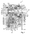
- FIG. 1 shows a partial section of a torque transmission device 1 as a double clutch in the drive train of a motor vehicle, consisting of a - not shown in detail - drive unit with a rotatably mounted in a wall 4a of the motor housing crankshaft 4 and a dual-clutch transmission with a rotating about a rotation axis 2a first transmission input shaft 2 and a second Transmission input shaft 3, which is formed in the embodiment shown as a hollow shaft.
- the torque transmission device 1 is housed in a so-called clutch bell 4b, which forms a closed space with the wall 4a.
- the torque transmission device 1 is divided into two friction clutches 10, 11 with radially superposed friction units 10a and 11a.
- Each friction clutch 10, 11 is in each case rotationally connected by means of an input part 10b, 11b to the crankshaft 4 and by means of an output part 10c, 11c, each having a transmission input shaft 2, 3.
- the two clutches 10, 11 respectively Reibpartner 12a, 12b and 13a, 13b associated with each of these the respective clutch 10, 11 associated disk set consisting of rotationally fixed to the Input part 10b, 11b connected friction partners 12a, 12b and rotationally fixed to the output part 10c, 11c connected friction partners 13a and 13b form.
- the number of friction partners and the arrangement of metallic and non-metallic friction surfaces can meet the requirements be interpreted below, it may be particularly advantageous if the total available friction surfaces of both friction clutches 10, 11 are designed so that a practically the same transferable torque results over both clutches. This can be done for example by a different number of friction partners 12a, 12b and 13a, 13b and / or by correspondingly different radial ring widths of the friction surfaces. However, it may also be advantageous in particular embodiments, for example in a dual-clutch transmission with a preferred starting gear on a transmission input shaft 2, 3, to provide the transmission input shaft associated clutch with a correspondingly larger transmission capacity. It is understood that the friction surfaces are formed from the sum of the surfaces of all friction partners.
- the coupling of the drive shaft 4 and transmission input shafts 2, 3 takes place by axial pressing of the friction partners 12a, 12b, 13a, 13b by means of one respective clutch 10, 11 associated actuating part 14a, 14b against one on the opposite side of the actuating members 14a, 14b provided Stop 15a, 15b.
- the stops 15a, 15b may be made of a circlip axially fixedly connected to the input or output part or of correspondingly impressed in the input or output part lugs, which may be distributed annularly or over the circumference.
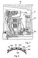
- the actuating parts 14a, 14b are preferably formed on the input parts 10b, 11b of the friction clutches 10, 11 as one-armed levers and technically preferably as components with a force edge and adjoining circumferentially distributed tongues or similar disc parts, wherein the in FIG. 2 solid lines the rest position with the clutch 10, 11 and the dashed lines, the operating parts 14a, 14b in the engaged position of the clutch 10, 11 show.
- the actuating parts 14a, 14b act on the friction units 10a, 11a by means of an urging element 14c, 14d, which is respectively arranged between the actuating part 14a, 14b and a friction partner 12a, 12b, so that with increasing actuation, that is, axial displacement of the radial inside of Actuating 14a, 14b at the same time axially fixed tension at the outer end corresponding to an axial lever axial relative displacement is transmitted to the friction units 10a, 11a, so that with increasing distance, the friction clutches 10, 11 a increasing torque transmitted from the crankshaft 4 to the respective associated transmission input shaft 2, 3.
- the transmission of the torque takes place for example by means of a toothing 2a, 3a between the respective transmission input shaft 2, 3 and the output parts 10c, 11c of the friction clutches 10, 11.
- the output parts can be massively forged, sintered or cast parts, as sheet metal parts or from a Combination of these may be formed, wherein the compounds of these parts may be welded or riveted.
- the actuating members 14a, 14b are preferably disc-shaped and / or stamped disc parts which may be formed to provide an elastic feature of spring steel and / or appropriately positioned at their ends. To increase the wear resistance they can be hardened.
- the operating parts 14a, 14b rotate at the same speed as the input parts of the clutch, so that the actuators 50a, 50b for actuating the operating parts 14a, 14b thereof must therefore be rotationally coupled by means of the actuating bearings 16a, 16b.
- the actuating bearings 16a, 16b would be so-called release bearings, while in the embodiment shown they are to be designated as engagement bearings.
- the actuating devices 50a, 50b are formed in the illustrated embodiment as hydraulic Nehmerritten 51a, 51b, which are displaced axially from the outside, for example by means of a pump unit or by means of a master cylinder, which in turn can be acted upon by an electric motor, by building a pressure and the actuating bearing 16a, 16b and the actuating members 14a, 14b act on the friction clutches.
- a plurality of circumferentially distributed receiver units 51a, 51b provided in such a way that they radially overlying actuation bearings 16a, 16b can act, although they are arranged to approximately a diameter over the circumference.
- a seal of the chamber 30 to the hydraulic Nehmerikien 51, 51b takes place with respect to the gear 56 on the side of the axial projection 50d of the housing 50c by means of seals, as shown here with reference to FIG. 50f.
- the torque transmission device 1 is provided in such a way that it can be mounted as a structural unit to the two-mass flywheel 80 connected in a rotationally fixed manner to the crankshaft 4.
- the actuators 50a, 50b are rotatably received fixedly on a disc-shaped component, so that the housing 50c of the actuators 50a, 50b can be rotatably received on a wall 56a of the dual-clutch transmission.
- the common housing 50c of the slave units 51a, 51b is connected by means of at least one projection 50d in a corresponding AufEnglishung of the transmission or a connected to the housing 56 of the transmission component 56b so that the resulting by the load moments of the actuating bearing 16a, 16b moment can be supported on the housing.
- a bearing 50e for example, a rolling or sliding bearing is provided between the housing 50c and attached to the component 19 receptacle 20a for receiving the gear housing 56, which supports the actuating force within the clutch, so that virtually no axial forces are introduced into the transmission housing ,
- the friction clutches 10, 11 are preferably wet-running friction clutches, that is, they are intended for operation in the oil bath.
- both clutches have a common input part 17, which is preferably designed pot-shaped open on one side, so that a housing 18 open on one side for the friction units 10a, 11a formed.
- the common input part 17 may be formed as a sheet metal part and in the region of the axis of rotation 2a, have a recess in which an axial projection 17a made of another, for example hardened material is introduced, the centering of the clutch on one of the two transmission input shafts 2, 3 (Fig. shown here: transmission input shaft 2) takes over.
- a pilot bearing 17b may be provided between the transmission input shaft 2 and the axial projection 17a. Furthermore, on the outer circumference of the projection 17 a rotationally contact with the output part 80a of the dual mass flywheel 80 may be provided, for example, as a connector 80b for mounting the torque transmitting device 1 on the dual mass flywheel. Furthermore, the axial projection 17a, with the interposition of a bearing such as slide bearing 4c, forms the abutment of the torque transmission device 1 on the crankshaft.
- the axial clearance between the torque transmitting device 1 and the crankshaft 4 is adjusted by firstly actuating the actuators 50a, 50b, the torque transmitting device 1 is spaced from the transmission housing 56 along the lugs 50d by pressure build-up of the slave units 51a, 51b and / or pressure in the is constructed with coolant at least partially filled chamber 30.
- a disk part 20 for example, a membrane is provided, which is sealed relative to the clutch bell 4b and opposite the input part 17, for example, here at the axial extension 17a, by means of a seal 17c.
- a pump 270 is contained within the clutch bell 4b, which is driven as a gear pump by the input part 17 of the friction clutches 10, 11.
- the input member 17 member 19 which is associated with this receptacle 20a with an axial projection 20b, which rotatably supported on its inner circumference on the bearing 20c and drives on its outer periphery the ring gear 272, wherein the pump housing fixed to the Transmission housing 56 is connected.
- the detailed explanation of the function of the pump 270 takes place in FIG.
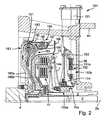
- FIG. 2 shows a torque transmission device 101 with per se similar friction clutches 10, 11 which can transmit a torque from the crankshaft 4 to the transmission input shafts 2, 3.
- the actuators 150a, 150b are angularly displaced from the axis of rotation 2a, so that only the actuator 150b is shown in detail. However, the actuator 150a is substantially provided with the same function.
- the actuating device 150a consists of a rotary drive 151, which can be arranged outside the clutch bell 4b and drives a spindle 151a.
- the spindle 151a forms with a cam 153, a gear 152, wherein the cam fixed to the housing is supported on the gear housing 56 and due to the rotational movement of the spindle 151a by means of the rotary drive 151 is radially displaced.
- the cam 153 acts on the one hand rotatably clamped and provided in the radial direction with an axial profile lever 154, so that upon rotation of the spindle 151a through the rotary drive 151, an axial displacement of the profiled lever 154 takes place, which acts on the engagement bearing 114a and thus the operating part 116a actuated, so that a clutch operation as under FIG. 1 he follows.
- the actuators 150a and 150b are detailed in FIG DE 103 40 528 A1 described and explained in more detail.
- FIG. 2 Another thought is in FIG. 2 provided on the dual mass flywheel 180.
- the dual-mass flywheel 180 is designed in such a way that a first mass 183 is connected directly to the crankshaft 4 on the primary side and a second mass 182 is rotatable relative to the first mass against the action of the energy store 181.
- a friction device 184 is provided between the two masses, which connects the two masses 182, 183 by the self-adjusting friction force.
- a substantially annular, axially projecting lug 185 is provided at the input part 180a of the dual mass flywheel 180 with the mass 183, at the inner circumference thereof against a radially inward direction acting energy storage 186 distributed over the circumference radially displaceable friction elements 187 provided with a form on the output part 180b of the dual mass flywheel 180 in cross-section U-shaped ring member 188 preferably with the interposition of friction linings 189 a frictional connection and thus connect the two masses 182 and 183 together.
- the function of the dual mass flywheel 180 is reduced to a predetermined speed of the crankshaft 4, the function of a simple flywheel.
- the mass of the friction elements 187 and the spring force of the energy storage 186 can be adjusted so that the release of the friction elements 187 takes place at a desired speed of the crankshaft 4.
- the two masses 182, 183 uncoupled at speeds higher idle speed.
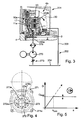
- FIG. 3 shows one of the torque transmission device 1 of FIG. 1 Similarly, torque transfer device 201 with a schematically illustrated circuit of a hydraulic device 202 for cooling the friction partners of the friction clutches 10, 11.
- a pump 270 as in, for example FIG. 1 pump integrated in the clutch bell 4b, which has an internal gear pump 271 (FIG. FIG. 4 ) and which can be driven by the torque transmission device 201, for example by means of the input part 17 of the two friction clutches 10, 11, the oil or coolant is applied to the two clutches via an oil cooler 276.
- the coolant flow in such a way that it preferably impinges first on the coupling 10, 11 with which the vehicle is predominantly approached.
- the oil is conveyed radially through the friction clutches 10a, 11a, preferably along the arrows 202a, 202b, by the friction clutches and compensates for the frictional heat generated by a differential rotational speed of the crankshaft 4 and the transmission input shafts 2 during a slip phase.
- the coolant flows through the line 203 shown schematically in a non-pressurized Swamp 204 from where it is brought by means of the pump 270 back into the hydraulic circuit for cooling the clutches 10, 11.
- FIG. 5 shows a corresponding diagram in which the volume flow Q is plotted against the rotational speed N of the crankshaft 4.
- the per se proportional course between the volume flow Q and the rotational speed N at coupled to the input part 17 of the torque transmitting device 201 pump 270 can be limited by the volume flow limiting valve or suction throttle at a predetermined speed limit N limit to a predetermined volume flow Q limit .
- the flow control valve consists of a suction throttle.
- an alternative control of the volume flow limiting valve can take place in such a way that the so-called slip speed is used as the controlled variable, the slip being determined from the rotational speed of each of a transmission input shaft 2, 3 and the crankshaft 4. From this, a volume flow of the pressure medium directly related to the cooling demand of the couplings 10, 11.
- FIG. 4 shows an advantageous embodiment of an internal gear pump 271, which is in the interior of the chamber 30 directly, so to speak locally, can be used.
- the internal gear pump 271 has a housing 271a that is stationary, for example on a wall 56a of the gear housing 56 (FIG. FIG. 1 ) is mounted.
- a ring gear 272 is provided, which, for example, from the hub 20b of a rotating component FIG. 1 is driven.
- the ring gear 272 meshes with the outer toothing 273a of the sun gear 273 to produce the pumping action.
- the Saugsichel 274 separates the suction from the pressure side and forms by means of a circular segment 274a a storage or centering for the sun gear 273 on the outer peripheries of the outer teeth 273a, so that it is not stored separately.
- Such an arrangement and configuration of a gear pump and its drive is not limited to the use of a coolant flow for cooling a clutch, but such an arrangement can also be provided for pressure supply device for the actuation of clutches and transmissions, for example of automated manual transmissions, automatic step transmissions, for Adjustment of adjusting cylinders of continuously variable belt drives and for the actuation of dry or wet friction clutches such as double clutches and torque converter lockup clutches.
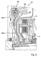
- FIG. 6 shows a torque transfer device 301 with a modified dual-mass flywheel 380 and two friction clutches 10, 11 as a partial section.
- the first and second masses 382, 383 are formed as shaped sheet metal parts and substantially aligned axially on the input part 380a or on the output part 380b such that the molded masses 382, 383 are substantially radially above the couplings 10 , 11 are arranged.
- FIG. 7 shows a partial section of a torque transmitting device 401, which in the manner of the torque transmission device 101 of the FIG. 2 modified is that instead of the actuators 150a, 150b in the form of lever release a hydraulic release system in the form of the actuators 50a, 50b - as in FIG. 1 described in more detail - are used. Only the actuating unit 50b is shown in this section. Furthermore, the torque transmission device 401 has a pump 270 arranged in the chamber 30 filled with cooling medium, as already described in US Pat FIG. 1 as well as in the Figures 3-5 was explained in more detail.
- FIG. 8 shows a detail of one of the devices 184 of the FIG. 2 and 584 of the FIG. 9 modified embodiment of a friction device 184a for coupling the two masses of a dual mass flywheel.
- receptacles for the energy store 186 are provided in the annular projection 185, for example stamped.
- the energy storage 186 apply radially limited, displaceable friction segments 189 a, which in the case of prestressing by means of the energy storage 186 a frictional engagement with a merely indicated, located in the cone of the friction segments 189a friction surface 189b (see FIG. 7 ) form.
- On the friction segments 189a or on the counter friction surface friction linings may be arranged.
- a further embodiment example can be provided, in particular for smaller coefficients of friction in wet clutches in lamellar construction, in which a frictionally engaged with a first mass member friction plate in both sides frictional contact with components of the other, to be connected via the frictional engagement with the first mass member component (see FIG. 9 ).
- a frictionally engaged with a first mass member friction plate in both sides frictional contact with components of the other to be connected via the frictional engagement with the first mass member component (see FIG. 9 ).
- a radially outwardly extended stop 189c is provided in the radially outward direction extended indentation 185b is extended and, when the friction segments 189a are displaced radially outward as a result of centrifugal force, the path of the friction segments 189a is radially limited.
- friction devices 184a can also be provided with friction devices radially outside and can connect any flywheel masses together. The coupling of electric machines with one or both masses of a dual-mass flywheel may also be preferred.
- FIG. 9 shows a partial section of a torque transmitting device 501 with an integrated into the chamber 530 filled with coolant dual mass flywheel 580 against the action of the energy storage 581 limited rotatable masses 582, 583.
- a friction device 584 is provided which differs from the previously described friction device 184 of FIG. 1 differs in that the friction element 589 is formed as a so-called friction plate with two friction surfaces, each forming a frictional contact with the input-side components 589a and the ring member 588.
- the friction element 589 is rotationally connected to the output-side part of the flywheel 580.
- the energy storage 581 are provided radially outside of the friction clutches 10, 11.
- the input part 580c of the dual-mass flywheel 580 which is connected to the crankshaft 4 by means of an axially elastic element 580d, acts on the energy store 851 from radially outside, while the output part 580a of the dual-mass flywheel feeds into the dual-mass flywheel 580 registered torque on the two clutches 10, 11 common input part 17 transmits.
- the output part 580a connected directly to the input part for example, be welded.
- a cup-shaped member 580e is provided on the outer circumference of the input part 580c, which is radially inwardly connected to a receiving part 580f, which is received and centered by a receptacle 586 which is fixedly connected to the transmission housing 56.
- a scoop tube 503 is further provided, which draws out due to centrifugal force forced outward coolant and the sump 204 ( FIG. 3 ) is supplied to the hydraulic circuit 202 (FIG. FIG. 3 ) for cooling the clutches 10, 11 to be available again.
- the drive of the pump by means of the receptacle 580f and the cup-shaped member 580e.
- FIG. 10 shows a relation to the torque transmission device 501 of FIG. 9 slightly modified embodiment of a torque transmission device 601 in partial section.
- the two-mass flywheel 680 which is likewise arranged in the coolant-filled chamber 630, is configured without a friction device for connecting the two masses 682, 683, wherein the mass 682 is configured in such a way that it is fixedly connected to the input part 17 of the couplings 10, 11 and is directly acted upon by an axially molded projection 682a of the energy storage and transmits via the crankshaft 4 and the input part 680c on the energy storage 681 transmitted torque to the input part 17.
- a further output part 680a engage in the energy storage 681, which is also connected directly to the input part 17 of the couplings 10, 11.
- this output part 680a can be formed from the input part 17 by issuing corresponding tabs.
- Approach 682a and output part 680a can act on different groups of the energy storage 681 and / or the parts 680a, 682a can be effective at different angles of rotation of the relative movement relative to the input part 680c against the energy storage 681, so that a two-stage characteristic of the dual mass flywheel 680 can be provided ,
- FIG. 11 shows an advantageous actuator 750 for the two friction clutches 10, 11 of the previously described torque transmitting devices with a Receiver unit 751, which are associated with two annular pistons 752, 753, which are arranged directly one above the other and radially above each other.
- the pistons 752, 753 are in each case axially displaced by a pressure applied from the outside to a chamber 752a, 753a, as a result of which the pistons 752, 753 actuate the actuating parts 14a, 14b by means of the actuating bearings 16a, 16b. FIG. 1 ) and thus engage the coupling.
- the engagement of the clutches 10, 11 takes place counter to an elasticity of the actuating parts 14a, 14b adjusting self-adjusting force, so that when reducing the pressure in the chambers 752a, 753a, the clutches are automatically reopened.
- the restoring force for closing the clutches can also be provided elsewhere, for example in encoder cylinders provided for pressure build-up, by corresponding energy storage materials such as helical springs.
- the in the FIGS. 12 and 13 shown torque transmission device 800 includes a torsional vibration damper 801, which has a connectable to the output shaft 802 of an engine primary part 803 and a rotatable relative to this secondary part 804.
- the primary part 803 and the secondary part 804 form flywheels having a corresponding moment of inertia.
- a friction clutch 806 is added with the interposition of a clutch disc 805.
- a torsionally elastic damper 807 is provided, which has two series-connected spring groups 808 and 809, which are accommodated here in a chamber 811 formed by sheet metal parts 810.
- the chamber 811 may preferably be at least partially filled with a lubricant.
- the two spring groups 808 and 809 are arranged axially one behind the other and practically at the same diameter.
- the primary part 803 has an axial extension 812, on which the secondary part 804 is rotatably mounted, in this case via a slide bearing.
- the series connection of the spring groups 808, 809 takes place in the illustrated embodiment of disk-shaped components which have corresponding receptacles for the springs 808 and 809 and here with the chamber 811 limiting sheet metal parts 810 are rotatably connected.
- the input part of the torsionally elastic damper is formed by a flange-like component 813, which is rotatably connected to the primary part 803.
- the output part of the torsionally elastic damper 801 is also formed by a flange-like component 814, which is non-rotatable with the secondary part 804.
- the chamber parts 811 forming sheet metal parts 810 and the associated with these Beauftschungsscalen for the springs 808 and 809 against the primary or input part 803 and secondary or output part 804 are arranged, that is, so arranged opposite these two parts rotatable ,
- a friction clutch or friction device 815 is furthermore provided, which also serves as a bridging clutch at low rotational speeds, for example below the idling rotational speed of the engine.
- the friction clutch 815 has flyweights 816 supported by an axial extension 817 of the primary 803.
- radial guide pins 818 are provided on the axial extension 817 for this purpose.
- the flyweights 816 which are formed in a segment-like manner over the circumference, are urged inward in the radial direction via springs 819, which are prestressed, and are supported by friction linings 820 on an axial projection 821, which is carried by the secondary part 804. from (at least below a certain speed).
- the axial projection 821 is formed in the illustrated embodiment by a cup-shaped sheet metal part 822 which is rotationally fixed to the secondary part 804.
- the friction clutch or lock-up clutch 815 is effective in parallel with the torsionally elastic damper 801, so that it can be bridged according to the design or bias of the springs 819 at least from a certain minimum speed.
- segment-like centrifugal weights 816 Due to the relatively large angular dimensioning of the segment-like centrifugal weights 816, these have a brake band-like reinforcing effect.
- three such centrifugal weights 816 are provided over the circumference, which practically each extend by 120 degrees.
- the secondary part 804 carries only a simple coupling.
- a double clutch could be provided, as described for example in connection with the other figures.
Claims (37)
- Dispositif de transmission de couple (1, 101, 201, 301, 401, 501, 601) pour la chaîne cinématique d'un véhicule automobile pour la transmission d'un couple entre un moteur à combustion interne avec un vilebrequin (4) et une boîte de vitesses à double embrayage, comprenant au moins deux arbres d'entrée de boîte de vitesses (2, 3) avec deux embrayages à friction (10, 11),- un arbre d'entrée de boîte de vitesses (2, 3) pouvant à chaque fois être accouplé au vilebrequin (4) au moyen, d'un embrayage à friction (10, 11) ;- chaque embrayage à friction (10, 11) disposant d'unités de friction côté entraînement et côté prise de force (10a, 11a), qui peuvent être sollicitées au moyen d'une pression axiale le long d'un axe de rotation (2a) d'au moins l'un des arbres d'entrée de boîte de vitesses (2, 3) l'un avec l'autre afin de former un engagement par friction ;- les unités de friction (10a, 11a) d'un embrayage à friction respectif (10, 11) étant sollicitées à l'encontre d'une butée (15a, 15b) au moyen d'une partie d'actionnement (14a, 14b) associée à l'unité de friction respective ;- un dispositif d'actionnement respectif (50a, 50b, 150a) agissant axialement sur la partie d'actionnement respective (14a, 14b) et connecté de manière solidaire en rotation à une partie de boîtier fixe (56) étant disposé avec la partie d'actionnement (14a, 14b) de chaque embrayage à friction (10, 11) en interposant un palier d'actionnement (16a, 16b) ;caractérisé en ce que :- les unités de friction (10a, 11a) sont formées d'une pluralité de partenaires de friction (12a, 12b, 13a, 13b) alternant par couches dans la direction axiale côté entraînement et côté prise de force ; et- les deux embrayages à friction (10, 11) sont utilisés en mode de fonctionnement humide.
- Dispositif de transmission de couple (1, 101, 201, 301, 401, 501, 601) selon la revendication 1, caractérisé en ce que les embrayages à friction (10, 11) sont disposés concentriquement et radialement l'un au-dessus de l'autre et la partie d'entrée (10b) de l'embrayage à friction extérieur (10) et la partie d'entrée (11b) de l'embrayage à friction intérieur (11) étant connectées l'une à l'autre de manière solidaire en rotation et axialement.
- Dispositif de transmission de couple (1, 101, 201, 301, 401, 501, 601) selon l'une quelconque des revendications 1 ou 2, caractérisé en ce qu'une partie d'entrée (17) montée en amont dans le flux de forces allant du moteur à combustion interne à la partie d'entrée (10b) est réalisée d'une seule pièce avec la partie d'entrée (10b) de l'embrayage à friction extérieur (10).
- Dispositif de transmission de couple (1, 101, 201, 301, 401, 501, 601) selon l'une quelconque des revendications 1 à 3, caractérisé en ce que les parties d'actionnement (14a, 14b) sont réalisées sous forme de ressorts Belleville ou d'agencements de leviers.
- Dispositif de transmission de couple (1, 101, 201, 301, 401, 501, 601) selon l'une quelconque des revendications 1 à 3, caractérisé en ce qu'au moins un dispositif d'actionnement est un dispositif d'actionnement électro-hydraulique (50a, 50b, 750).
- Dispositif de transmission de couple (1, 101, 201, 301, 401, 501, 601) selon la revendication 5, caractérisé en ce que l'au moins un dispositif d'actionnement (50a, 50b, 750) est formé d'une unité hydraulique émettrice pouvant être actionnée au moyen d'un moteur électrique, constituée d'une unité cylindre/piston, d'au moins une unité hydraulique réceptrice (51a, 51b, 251a) sollicitant axialement le palier d'actionnement correspondant (16a, 16b), constituée d'une unité cylindre/piston, et d'une conduite de fluide sous pression reliant l'unité émettrice et l'unité réceptrice.
- Dispositif de transmission de couple (1, 101, 201, 301, 401, 501, 601) selon la revendication 6, caractérisé en ce que l'au moins un dispositif d'actionnement (50a, 50b) présente plusieurs unités réceptrices (51a, 51b) réparties sur la périphérie, disposées autour d'un arbre d'entrée de boîte de vitesses (2, 3), pour solliciter un palier d'actionnement (16a, 16b).
- Dispositif de transmission de couple (1, 101, 201, 301, 401, 501, 601) selon la revendication 7, caractérisé en ce que les deux dispositifs d'actionnement (50a, 50b) présentent des unités réceptrices (51a, 51b) réparties sur la périphérie et celles-ci sont réparties en alternance sur la périphérie en fonction de leur affectation au dispositif d'actionnement et sont disposées sur la même périphérie.
- Dispositif de transmission de couple selon la revendication 6, caractérisé en ce que l'au moins un dispositif d'actionnement (750) présente une unité réceptrice (751) disposée autour d'un arbre d'entrée de boîte de vitesses, avec un piston annulaire (752, 753) pour solliciter un palier d'actionnement (16a, 16b).
- Dispositif de transmission de couple selon la revendication 1, caractérisé en ce qu'au moins un dispositif d'actionnement présente au moins une unité réceptrice qui est alimentée et commandée par une partie de commande pour la commande hydraulique des rapports de transmission.
- Dispositif de transmission de couple selon la revendication 10, caractérisé en ce que l'au moins une unité réceptrice est montée dans une paroi de boîtier de la boîte de vitesses à double embrayage.
- Dispositif de transmission de couple selon la revendication 11, caractérisé en ce qu'au moins un cylindre pour l'au moins une unité réceptrice est formé par la paroi de boîtier et un piston déplaçable axialement, sollicitant le palier d'actionnement correspondant, est monté dans le cylindre.
- Dispositif de transmission de couple (201) selon la revendication 1, caractérisé en ce qu'au moins un dispositif d'actionnement est un dispositif d'actionnement électromécanique (150b).
- Dispositif de transmission de couple (101) selon la revendication 13, caractérisé en ce que la sollicitation d'au moins un embrayage à friction (10, 11) a lieu au moyen d'un entraînement en rotation (151) par moteur électrique disposé essentiellement perpendiculairement à l'un des arbres d'entrée de boîte de vitesses (2, 3), le mouvement de rotation étant converti au moyen d'une transmission (152) en un mouvement de translation le long de l'un des arbres d'entrée de boîte de vitesses (2, 3) pour la sollicitation du palier d'actionnement correspondant.
- Dispositif de transmission de couple selon la revendication 13, caractérisé en ce que la sollicitation d'au moins un embrayage à friction (10, 11) a lieu au moyen d'un entraînement en rotation par moteur électrique disposé essentiellement parallèlement à l'un des arbres d'entrée de boîte de vitesses (2, 3), le mouvement de rotation étant converti au moyen d'une transmission en un mouvement de translation le long de cet arbre d'entrée de boîte de vitesses pour solliciter le palier d'actionnement correspondant.
- Dispositif de transmission de couple (1, 201, 401) selon l'une quelconque des revendications précédentes, caractérisé en ce qu'un flux de réfrigérant pour le refroidissement d'au moins un embrayage à friction (10, 11) est fourni au moyen d'une pompe (270) qui est disposée dans la région d'une paroi (56a) de la boîte de vitesses à double embrayage tournée vers la cloche d'embrayage.
- Dispositif de transmission de couple (1, 201, 401) selon la revendication 16, caractérisé en ce que la pompe (270) est utilisée exclusivement pour fournir le flux de réfrigérant.
- Dispositif de transmission de couple (1, 201, 401) selon la revendication 16 ou 17, caractérisé en ce que la pompe (270) est entraînée par le vilebrequin (4) ou par un composant (19) relié à celui-ci.
- Dispositif de transmission de couple (1, 201, 401) selon l'une quelconque des revendications 17 à 18, caractérisé en ce que la pompe (270) est une pompe à engrenages internes (271) avec une couronne dentée (272) avec une denture interne (272a), avec laquelle s'engrène une roue solaire (273) avec une denture extérieure (273a), un croissant d'aspiration (274) pour l'aspiration du réfrigérant étant prévu et la roue solaire (273) étant supportée radialement au moyen de sa denture extérieure (273a) sur un segment (274a) complémentaire à celle-ci du croissant d'aspiration (274).
- Dispositif de transmission de couple (1, 201, 401) selon la revendication 19, caractérisé en ce que la couronne dentée (272) est entraînée par un composant d'entraînement (20b).
- Dispositif de transmission de couple (201) selon l'une quelconque des revendications 16 à 18, caractérisé en ce que la pompe (270) est une pompe Gerotor.
- Dispositif de transmission de couple (201) selon l'une quelconque des revendications 15 à 21, caractérisé en ce qu'un débit volumique produit par la pompe (270) est régulé au moyen d'un étranglement d'aspiration (275).
- Dispositif de transmission de couple (201) selon la revendication 22, caractérisé en ce que la commande a lieu au moyen d'une électrovanne.
- Dispositif de transmission de couple (201) selon l'une quelconque des revendications 15 à 23, caractérisé en ce qu'entre la pompe (270) et les unités de friction (10a, 11a) est monté un refroidisseur d'huile (276).
- Dispositif de transmission de couple (201) selon l'une quelconque des revendications précédentes, caractérisé en ce que dans une cloche d'embrayage (4b) entre une paroi (4a) du moteur à combustion interne et une paroi (56a) de la boîte de vitesses à double embrayage est formée une chambre séparée (30, 530) scellée de manière étanche aux fluides vis-à-vis de la cloche d'embrayage, dans laquelle chambre sont reçus au moins les deux embrayages à friction (10, 11).
- Dispositif de transmission de couple (501) selon l'une quelconque des revendications 1 à 25, caractérisé en ce que les deux embrayages à friction (10, 11) sont saisis radialement sur leur pourtour par un composant côté entraînement (580c, 580e), lequel est prévu en tant que partie d'entrée pour les deux embrayages à friction (10, 11).
- Dispositif de transmission de couple selon la revendication 26, caractérisé en ce que la partie d'entrée est réalisée sous forme de pot et est prévue en tant que partie d'un boîtier pour réaliser l'étanchéité de la chambre (530) par rapport à la cloche d'embrayage.
- Dispositif de transmission de couple (1, 101, 201, 301, 401, 501, 601) selon l'une quelconque des revendications précédentes, caractérisé en ce qu'entre le vilebrequin (4) et la partie d'entrée (17) des deux embrayages à friction (10, 11) est prévu un volant d'inertie à deux masses (80, 180, 380, 580, 680).
- Dispositif de transmission de couple (501, 601) selon la revendication 28, caractérisé en ce que le volant d'inertie à deux masses (580, 680) est intégré dans la chambre (530, 630).
- Dispositif de transmission de couple (1, 101, 201, 301, 401) selon la revendication 28, caractérisé en ce que le volant d'inertie à deux masses (80, 180, 380) est disposé en dehors de la chambre (30).
- Dispositif de transmission de couple (101, 401, 501) selon l'une quelconque des revendications 29 ou 26, caractérisé en ce que deux masses (182, 183 ; 482, 483, 582, 583), pouvant tourner relativement à l'encontre d'au moins un accumulateur d'énergie (181, 481, 581) agissant dans la direction périphérique, peuvent être accouplées au moins temporairement l'une avec l'autre.
- Dispositif de transmission de couple (101, 401, 501) selon la revendication 31, caractérisé en ce que l'accouplement a lieu au moyen d'un dispositif de friction dépendant de la force centrifuge (184, 584).
- Dispositif de transmission de couple (101, 401, 501) selon la revendication 31 ou 32, caractérisé en ce qu'une première masse pouvant être accouplée côté entraînement présente un couple d'inertie de 0,1 ± 0,04 kgm2 et une deuxième masse côté entraînement présente un couple d'inertie de 0,04 ± 0,04 kgm2.
- Dispositif de transmission de couple (101, 401, 501) selon la revendication 33, caractérisé en ce que l'accouplement des deux masses est efficace jusqu'à une plage de 1200 à 1800 rotations.
- Boîte de vitesses à double embrayage comprenant un dispositif de transmission de couple (1, 101, 201, 301, 401, 501, 601) selon les revendications 1 à 34.
- Chaîne cinématique comprenant un moteur à combustion interne et une boîte de vitesses à double embrayage avec un dispositif de transmission de couple (1, 101, 201, 301, 401, 501, 601) selon les revendications 1 à 34 disposé entre ceux-ci.
- Utilisation d'un dispositif de transmission de couple (1, 101, 201, 301, 401, 501, 601) selon les revendications 1 à 34 pour une chaîne cinématique dans un véhicule automobile.
Applications Claiming Priority (2)
| Application Number | Priority Date | Filing Date | Title |
|---|---|---|---|
| DE10361491 | 2003-12-23 | ||
| DE10361491 | 2003-12-23 |
Publications (4)
| Publication Number | Publication Date |
|---|---|
| EP1548313A2 EP1548313A2 (fr) | 2005-06-29 |
| EP1548313A3 EP1548313A3 (fr) | 2006-06-07 |
| EP1548313B1 true EP1548313B1 (fr) | 2013-07-03 |
| EP1548313B2 EP1548313B2 (fr) | 2016-09-28 |
Family
ID=34530412
Family Applications (1)
| Application Number | Title | Priority Date | Filing Date |
|---|---|---|---|
| EP04029777.2A Active EP1548313B2 (fr) | 2003-12-23 | 2004-12-16 | Dispositif de transmission de couple et train d'entraînement le comprenant |
Country Status (8)
| Country | Link |
|---|---|
| US (1) | US7287634B2 (fr) |
| EP (1) | EP1548313B2 (fr) |
| JP (1) | JP2005180702A (fr) |
| KR (1) | KR20050065354A (fr) |
| CN (1) | CN100557260C (fr) |
| BR (1) | BRPI0405845A (fr) |
| DE (1) | DE102004061020B4 (fr) |
| RU (1) | RU2004137560A (fr) |
Cited By (1)
| Publication number | Priority date | Publication date | Assignee | Title |
|---|---|---|---|---|
| DE102018125574A1 (de) | 2018-06-12 | 2019-12-12 | Schaeffler Technologies AG & Co. KG | Kraftfahrzeug-Kupplungsnehmerzylinder mit einem Stahlflansch und einem kunststoffumfassenden Druckraumbegrenzungsteil sowie eine Kraftfahrzeugkupplung |
Families Citing this family (105)
| Publication number | Priority date | Publication date | Assignee | Title |
|---|---|---|---|---|
| EP1561961B1 (fr) | 2004-02-05 | 2007-09-12 | LuK Lamellen und Kupplungsbau Beteiligungs KG | Dispositif d'embrayage multiple |
| DE102005063529B4 (de) | 2004-06-21 | 2020-01-16 | Schaeffler Technologies AG & Co. KG | Nasslaufende Doppelkupplung in Lamellenbauweise |
| DE502005005856D1 (de) * | 2004-06-21 | 2008-12-18 | Luk Lamellen & Kupplungsbau | Drehmomentübertragungseinrichtung |
| DE102005009187A1 (de) * | 2005-03-01 | 2006-09-14 | Zf Friedrichshafen Ag | Torsionsschwingungsdämpfer |
| ATE542039T1 (de) * | 2005-03-26 | 2012-02-15 | Schaeffler Technologies Gmbh | Verbundgetriebe |
| JP2006322554A (ja) * | 2005-05-19 | 2006-11-30 | Nsk Warner Kk | 多板摩擦クラッチ装置 |
| JP4590307B2 (ja) * | 2005-05-19 | 2010-12-01 | Nskワーナー株式会社 | 多板摩擦クラッチ装置 |
| US7497312B2 (en) * | 2005-08-10 | 2009-03-03 | Borgwarner Inc. | Clutch assembly |
| WO2007051627A1 (fr) * | 2005-11-04 | 2007-05-10 | Borgwarner Inc. | Amortisseur de vibrations de torsion avec un accouplement a un vilebrequin et combinaison d'un amortisseur de vibrations de torsion et d'un accouplement |
| JP4405464B2 (ja) * | 2005-12-28 | 2010-01-27 | 本田技研工業株式会社 | ツインクラッチ装置 |
| EP1906042B1 (fr) | 2005-12-28 | 2009-04-15 | Honda Motor Co., Ltd. | Dispositif d'embrayage double |
| JP2009527700A (ja) | 2006-02-22 | 2009-07-30 | ルーク ラメレン ウント クツプルングスバウ ベタイリグングス コマンディートゲゼルシャフト | クラッチディスクを取り付けるための開口を備えたクラッチハウジング |
| US7823711B2 (en) | 2006-02-22 | 2010-11-02 | Luk Lamellen Und Kupplungsbau Beteiligungs Kg | Dual clutch pack dual operating clutch and method for adjusting same |
| US8944229B2 (en) * | 2006-02-22 | 2015-02-03 | Schaeffler Technologies AG & Co. KG | Clutch housing with wide lever spring retention slots and clutch housing with axially off-set tabs |
| US9188167B2 (en) * | 2006-02-22 | 2015-11-17 | Schaeffler Technologies AG & Co. KG | Clutch housing with lever spring retention slots and method of installing a lever spring |
| US20070193850A1 (en) * | 2006-02-22 | 2007-08-23 | Luk Lamellen Und Kupplungsbau Beteiligungs Kg | Clutch housing with openings to engage a clutch plate |
| US7854306B2 (en) * | 2006-02-22 | 2010-12-21 | Schaeffler Technologies Gmbh & Co. Kg | Clutch assembly with an oil pump clutch housing and a carrier engaged with a clutch pack outer circumference |
| WO2007095882A1 (fr) | 2006-02-22 | 2007-08-30 | Luk Lamellen Und Kupplungsbau Beteiligungs Kg | Carter d'embrayage doté de larges fentes d'arrêt pour un ressort levier et carter d'embrayage doté de languettes à décalage axial |
| DE102007004990A1 (de) * | 2006-02-28 | 2007-08-30 | Luk Lamellen Und Kupplungsbau Beteiligungs Kg | Kupplungsvorrichtung |
| DE102006010113C5 (de) | 2006-02-28 | 2010-05-20 | Getrag Getriebe- Und Zahnradfabrik Hermann Hagenmeyer Gmbh & Cie Kg | Doppelkupplungsanordnung für ein Doppelkupplungsgetriebe |
| DE112007000304B4 (de) | 2006-03-07 | 2017-02-23 | Schaeffler Technologies AG & Co. KG | Kupplungsaggregat mit Nasslaufkupplung |
| DE112007000452A5 (de) | 2006-04-04 | 2008-11-27 | Luk Lamellen Und Kupplungsbau Beteiligungs Kg | Radiale Stromungskammer für Kupplungen in einer Kupplungsbaugruppe |
| EP1870610B1 (fr) * | 2006-06-20 | 2013-01-16 | Schaeffler Technologies AG & Co. KG | Système de levier et son procédé de montage |
| WO2008034431A2 (fr) * | 2006-09-20 | 2008-03-27 | GIF Gesellschaft für Industrieforschung mbH | Chaîne cinématique avec un arbre d'entraînement principal, et chaîne cinématique pour un véhicule automobile avec un arbre d'entraînement sortant notamment d'un bloc-moteur |
| DE102006045163A1 (de) * | 2006-09-25 | 2008-04-03 | Robert Bosch Gmbh | Doppelkupplung für ein Doppelkupplungsgetriebe |
| DE112007003802B3 (de) | 2006-10-13 | 2018-09-13 | Ricardo Uk Ltd. | Kupplungsanordnung mit einem Wärmeübertragungsmedium zum Kühlen einer Antriebsplatte |
| EP1916421B1 (fr) * | 2006-10-16 | 2016-11-09 | Schaeffler Technologies AG & Co. KG | Agencement d'entraînement de pompe |
| US8074534B2 (en) * | 2007-07-30 | 2011-12-13 | Caterpillar Inc. | Flywheel having lubrication-flow passageway |
| DE102008039029A1 (de) | 2007-09-04 | 2009-03-05 | Luk Lamellen Und Kupplungsbau Beteiligungs Kg | Reibbelag |
| DE102008008062B4 (de) | 2008-02-01 | 2014-05-22 | Getrag Getriebe- Und Zahnradfabrik Hermann Hagenmeyer Gmbh & Cie Kg | Doppelkupplungsanordnung |
| DE102009012283A1 (de) * | 2008-04-19 | 2009-10-22 | Borgwarner Inc., Auburn Hills | Mehrfachkupplungseinrichtung mit einem Drehmomentübertragungselement und Getriebe-Kupplungs-Anordnung mit einer solchen Mehrfachkupplungseinrichtung |
| DE102008060580B4 (de) * | 2008-06-03 | 2021-01-21 | Borgwarner Inc. | Mehrfach-Kupplungseinrichtung mit zwei Druckausgleichsräumen |
| JP5210762B2 (ja) * | 2008-08-25 | 2013-06-12 | 株式会社小松製作所 | モータグレーダ |
| CN102066814B (zh) * | 2008-08-07 | 2013-10-02 | 株式会社小松制作所 | 机动平地机 |
| US20100075794A1 (en) * | 2008-09-24 | 2010-03-25 | Luk Lamellen Und Kupplungsbau Beteiligungs Kg | Transmission actuation system |
| DE102008055681B4 (de) | 2008-10-28 | 2020-10-15 | Magna Pt B.V. & Co. Kg | Doppelkupplungsanordnung für ein Doppelkupplungsgetriebe |
| DE102008055682C5 (de) | 2008-10-28 | 2017-11-02 | Getrag Getriebe- Und Zahnradfabrik Hermann Hagenmeyer Gmbh & Cie Kg | Doppelkupplung mit stehendem Kolben und verbesserten Einrücklagern |
| US20100140036A1 (en) * | 2008-12-08 | 2010-06-10 | Gm Global Technology Operations, Inc. | Compact dry dual clutch module |
| DE102009059929A1 (de) * | 2009-01-19 | 2010-07-22 | Luk Lamellen Und Kupplungsbau Beteiligungs Kg | Kupplungsaggregat mit Drehschwingungsdämpfer |
| WO2010081454A1 (fr) * | 2009-01-19 | 2010-07-22 | Luk Lamellen Und Kupplungsbau Beteiligungs Kg | Système à embrayages multiples |
| DE102010018989A1 (de) * | 2009-05-20 | 2010-11-25 | Luk Lamellen Und Kupplungsbau Beteiligungs Kg | Doppelnasskupplung |
| DE102010018941B4 (de) | 2009-05-28 | 2018-11-29 | Schaeffler Technologies AG & Co. KG | Geteiltes Schwungrad |
| DE102009028387A1 (de) * | 2009-08-10 | 2011-02-17 | Zf Friedrichshafen Ag | Getriebeanordnung für ein Fahrzeug |
| CN102483104B (zh) * | 2009-08-20 | 2015-06-17 | 舍弗勒技术股份两合公司 | 隔板和汽车变速器 |
| DE102009038344B4 (de) * | 2009-08-21 | 2019-02-21 | Volkswagen Ag | Antriebsstrangmodul für ein Kraftfahrzeug |
| US8485333B2 (en) * | 2009-08-26 | 2013-07-16 | GM Global Technology Operations LLC | Actuation device for a dual clutch transmission |
| US8636125B2 (en) * | 2009-08-26 | 2014-01-28 | GM Global Technology Operations LLC | Actuation device having wiper seals for a dual clutch transmission |
| JP2011089632A (ja) * | 2009-09-28 | 2011-05-06 | Ntn Corp | 車両用電動モータ駆動装置 |
| US8365893B2 (en) * | 2009-10-02 | 2013-02-05 | GM Global Technology Operations LLC | Dual clutch |
| DE112010004776A5 (de) * | 2009-10-19 | 2012-11-22 | Schaeffler Technologies AG & Co. KG | Drehmomentübertragungseinrichtung |
| GB2474517A (en) * | 2009-10-19 | 2011-04-20 | Gm Global Tech Operations Inc | A clutch actuation device for a dual clutch including concentric slave cylinders |
| DE102010051447A1 (de) * | 2009-11-20 | 2011-05-26 | Schaeffler Technologies Gmbh & Co. Kg | Kupplungseinrichtung |
| CN102695891B (zh) * | 2009-11-24 | 2015-06-03 | 舍弗勒技术股份两合公司 | 转矩传递装置 |
| DE102010051911A1 (de) * | 2009-11-25 | 2011-06-01 | Schaeffler Technologies Gmbh & Co. Kg | Mehrfachkupplungsvorrichtung, Bauteil, Baugruppen und Verfahren zur Montage |
| DE102011014097A1 (de) * | 2010-03-25 | 2011-09-29 | Schaeffler Technologies Gmbh & Co. Kg | Doppelkupplung |
| DE102010023840B4 (de) | 2010-06-09 | 2022-12-01 | Magna Pt B.V. & Co. Kg | Reibkupplungsanordnung für einen Kraftfahrzeugantriebsstrang |
| US8474589B2 (en) * | 2010-07-27 | 2013-07-02 | Ebo Group, Inc. | Compact universal fluid-actuated clutch |
| WO2012013173A1 (fr) * | 2010-07-29 | 2012-02-02 | Schaeffler Technologies Gmbh & Co. Kg | Dispositif d'embrayage |
| JP4932934B2 (ja) | 2010-10-19 | 2012-05-16 | 株式会社エクセディ | 流体式動力伝達装置のロックアップ装置 |
| DE112012000840B4 (de) * | 2011-02-16 | 2024-01-25 | Schaeffler Technologies AG & Co. KG | Drehmomentübertragungseinrichtung |
| DE112012000827A5 (de) * | 2011-02-16 | 2013-11-07 | Schaeffler Technologies AG & Co. KG | Drehmomentübertragungseinrichtung |
| US8790212B2 (en) * | 2011-02-22 | 2014-07-29 | Schaeffler Technologies Gmbh & Co. Kg | Planetary clutch assembly, for a transmission, with a common actuator for two clutches |
| FR2972036B1 (fr) * | 2011-02-25 | 2013-04-12 | Valeo Embrayages | Amortisseur de torsion pour un embrayage |
| JP5544044B2 (ja) * | 2011-06-16 | 2014-07-09 | 本田技研工業株式会社 | 変速機用クラッチ |
| WO2012175060A1 (fr) * | 2011-06-21 | 2012-12-27 | Schaeffler Technologies AG & Co. KG | Dispositif de transmission de couple de rotation |
| US20130323015A1 (en) | 2012-05-31 | 2013-12-05 | Dana Heavy Vehicle Systems Group, Llc | Power Distribution Unit With A Forced Lubrication Flow Assembly |
| JP5890263B2 (ja) * | 2012-06-27 | 2016-03-22 | アイシン精機株式会社 | 動力伝達装置 |
| DE102012212461A1 (de) * | 2012-07-17 | 2014-05-22 | Bayerische Motoren Werke Aktiengesellschaft | Zweimassenschwungrad |
| DE102013211688B4 (de) | 2012-07-18 | 2021-12-23 | Schaeffler Technologies AG & Co. KG | Doppelkupplungseinrichtung |
| DE102012021074B4 (de) | 2012-10-19 | 2016-05-04 | Getrag Getriebe- Und Zahnradfabrik Hermann Hagenmeyer Gmbh & Cie Kg | Verfahren zum Betreiben eines Hybrid-Antriebsstranges |
| EP2762752B1 (fr) * | 2013-01-30 | 2017-06-21 | C.R.F. Società Consortile per Azioni | boîte de vitesses pour véhicule |
| DE112014001648A5 (de) * | 2013-03-26 | 2015-12-03 | Schaeffler Technologies AG & Co. KG | Doppelkupplung mit Vorspannung von Verbindungssteg zu Außenträger |
| CN104074877B (zh) * | 2013-03-26 | 2018-08-14 | 舍弗勒技术股份两合公司 | 钢制片避免间隙地接合的干式片式离合器 |
| DE102014211633A1 (de) * | 2013-07-03 | 2015-01-08 | Schaeffler Technologies Gmbh & Co. Kg | Lamellenträger für eine Doppelkupplung |
| DE102014215139A1 (de) * | 2013-08-14 | 2015-02-19 | Schaeffler Technologies Gmbh & Co. Kg | Rotorintegrierte Trennkupplung mit zweistufiger Kupplungsübersetzung |
| CN105683615B (zh) | 2013-10-31 | 2017-12-15 | Valeo离合器公司 | 次级构件的扭矩波动过滤机构 |
| EP3084248B1 (fr) * | 2013-12-16 | 2017-09-13 | Schaeffler Technologies AG & Co. KG | Dispositif d'embrayage à hydraulique entièrement intégrée |
| DE102014014236A1 (de) * | 2014-02-22 | 2015-08-27 | Borgwarner Inc. | Antriebsstrang für ein Kraftfahrzeug und Verfahren zum Betrieb eines solchen Antriebsstrangs |
| DE102014212421A1 (de) * | 2014-06-27 | 2015-12-31 | Schaeffler Technologies AG & Co. KG | Nasse Lamellendoppelkupplung mit Hebeln außerhalb des Nassraums |
| CN104315010B (zh) * | 2014-09-29 | 2016-08-31 | 沈琴仙 | 双板式离合器机构和包括双板式离合器机构的机械变速器 |
| DE102015206060A1 (de) | 2015-04-02 | 2016-10-06 | Zf Friedrichshafen Ag | Doppelkupplungsanordnung, Doppelkupplungsgetriebeanordnung sowie Kraftfahrzeug |
| US9500259B1 (en) | 2015-08-11 | 2016-11-22 | Gm Global Technology Operations, Llc | High performance torsional vibration isolator |
| CN105020296B (zh) * | 2015-08-18 | 2018-01-16 | 崔博琳 | 机械压紧摩擦片的湿式双离合器机构 |
| CN106499742B (zh) * | 2015-09-03 | 2019-11-19 | 舍弗勒技术股份两合公司 | 离合器装置 |
| WO2017110191A1 (fr) | 2015-12-25 | 2017-06-29 | 日本精工株式会社 | Appareil de transfert de rotation comprenant un dispositif de mesure de couple |
| DE102016201219A1 (de) * | 2016-01-28 | 2017-08-03 | Schaeffler Technologies AG & Co. KG | Kupplungseinrichtung für Hybridantrieb |
| US10006517B2 (en) | 2016-03-03 | 2018-06-26 | GM Global Technology Operations LLC | Torsional vibration damper with planetary gear enhanced by inertial mass |
| KR101803952B1 (ko) * | 2016-05-25 | 2017-12-01 | 한국파워트레인 주식회사 | 차량용 토크 컨버터 |
| FR3051861B1 (fr) * | 2016-05-31 | 2019-07-26 | Valeo Embrayages | Systeme de refroidissement pour mecanisme d’embrayage |
| US10337562B2 (en) | 2016-06-17 | 2019-07-02 | GM Global Technology Operations LLC | Clutch for a transmission |
| DE102016217218A1 (de) * | 2016-09-09 | 2018-03-15 | Schaeffler Technologies AG & Co. KG | Kupplungseinrichtung |
| FR3058098B1 (fr) * | 2016-10-27 | 2024-01-19 | Valeo Embrayages | Dispositif de transmission pour vehicule hybride |
| US10323698B2 (en) | 2016-11-01 | 2019-06-18 | GM Global Technology Operations LLC | Torque transferring clutch separation |
| CN110199135A (zh) * | 2016-11-23 | 2019-09-03 | 莱纳玛公司 | 用于串联车轴组件的分离式离合器 |
| DE102018108396A1 (de) * | 2018-01-23 | 2019-07-25 | Schaeffler Technologies AG & Co. KG | Mehrfachkupplung mit Geberteil zur Drehzahlerfassung; und Kupplungsanordnung mit Mehrfachkupplung sowie Zweimassenschwungrad |
| DE102018104367A1 (de) * | 2018-02-27 | 2019-08-29 | Schaeffler Technologies AG & Co. KG | Kupplungsanordnung mit modularer Struktur, sowie Antriebseinheit |
| JP2019178736A (ja) * | 2018-03-30 | 2019-10-17 | 本田技研工業株式会社 | 車両の制御装置 |
| DE102018111909B4 (de) * | 2018-05-17 | 2019-12-12 | Schaeffler Technologies AG & Co. KG | Kupplungseinrichtung |
| DE102018113717B4 (de) * | 2018-06-08 | 2020-06-18 | Schaeffler Technologies AG & Co. KG | Kupplungseinrichtung |
| KR102107375B1 (ko) * | 2018-07-06 | 2020-05-07 | 주식회사 서진오토모티브 | 듀얼 클러치 |
| RU2690118C1 (ru) * | 2018-08-01 | 2019-05-30 | Федеральное государственное унитарное предприятие "Центральный ордена Трудового Красного Знамени научно-исследовательский автомобильный и автомоторный институт "НАМИ" (ФГУП "НАМИ") | Двойное сцепление с гасителем крутильных колебаний |
| RU2689670C1 (ru) * | 2018-08-01 | 2019-05-28 | Федеральное государственное унитарное предприятие "Центральный ордена Трудового Красного Знамени научно-исследовательский автомобильный и автомоторный институт "НАМИ" (ФГУП "НАМИ") | Двойное сцепление |
| RU2702474C1 (ru) * | 2019-01-30 | 2019-10-08 | Федеральное государственное унитарное предприятие "Центральный ордена Трудового Красного Знамени научно-исследовательский автомобильный и автомоторный институт "НАМИ" (ФГУП "НАМИ") | Способ монтажа двойного сцепления в картер коробки передач |
| DE102019133282B3 (de) * | 2019-12-06 | 2021-05-20 | Schaeffler Technologies AG & Co. KG | Kupplungseinrichtung |
| DE102021105911A1 (de) | 2021-03-11 | 2022-09-15 | Schaeffler Technologies AG & Co. KG | Druckring mit werkzeugfallend ausgeformter axialer Anschlagskontur für einen Sicherungsring; Druckringanordnung sowie Reibkupplung |
Citations (3)
| Publication number | Priority date | Publication date | Assignee | Title |
|---|---|---|---|---|
| EP1134447A2 (fr) * | 2000-03-16 | 2001-09-19 | Mannesmann Sachs Aktiengesellschaft | Configuration de double embrayage |
| EP1174631A2 (fr) * | 2000-07-17 | 2002-01-23 | Mannesmann Sachs Aktiengesellschaft | Dispositif d'accouplement multiple |
| DE10155458A1 (de) * | 2000-11-22 | 2002-05-23 | Luk Lamellen & Kupplungsbau | Kupplungsaggregat |
Family Cites Families (34)
| Publication number | Priority date | Publication date | Assignee | Title |
|---|---|---|---|---|
| US173429A (en) * | 1876-02-15 | Improvement in refrigerators | ||
| US2485688A (en) † | 1944-12-26 | 1949-10-25 | New Prod Corp | Axially engaging multiple fluid clutch |
| US2636585A (en) * | 1946-08-30 | 1953-04-28 | William T Livermore | Automatic fluid pressure transmission |
| US2775330A (en) † | 1952-11-21 | 1956-12-25 | Gen Motors Corp | Transmission and control system |
| US3734259A (en) * | 1970-07-10 | 1973-05-22 | Brown Tractors Ltd | Liquid cooled clutches |
| DE2904666A1 (de) † | 1978-02-16 | 1979-08-30 | Thermo King Corp | Zahnradpumpe |
| DE3005657A1 (de) † | 1980-02-15 | 1981-08-20 | Zahnradfabrik Friedrichshafen Ag, 7990 Friedrichshafen | Zahnradpumpe |
| DE3202179A1 (de) † | 1982-01-25 | 1983-08-04 | Schwäbische Hüttenwerke GmbH, 7080 Aalen | Schalt- und/oder fuellpumpe fuer ein automatisches getriebe |
| JPS59131035A (ja) † | 1983-01-14 | 1984-07-27 | Nissan Motor Co Ltd | 湿式クラツチ |
| DE4134369B4 (de) † | 1990-10-20 | 2004-08-26 | Zf Friedrichshafen Ag | Getriebegehäuse für ein Automatgetriebe eines Kraftfahrzeugs |
| DE4139611A1 (de) † | 1991-11-30 | 1993-06-03 | Zahnradfabrik Friedrichshafen | Getriebe mit einer verdraengerpumpe |
| DE29621361U1 (de) † | 1996-12-11 | 1997-03-27 | Bavaria Pumpen Gmbh | Flüssigkeitspumpe nach dem Rotorprinzip |
| DE19710379C1 (de) † | 1997-03-13 | 1998-08-20 | Luk Fahrzeug Hydraulik | Sauggedrosselte Pumpe |
| DE19750675C1 (de) † | 1997-11-15 | 1998-08-13 | Zahnradfabrik Friedrichshafen | Ölpumpe |
| US6179595B1 (en) † | 1998-05-27 | 2001-01-30 | Luk Getriebe-Systeme Gmbh | Hydraulic gear machine having a transmission shaft in a bearing tube |
| DE19921687C5 (de) * | 1999-05-12 | 2016-06-09 | Borgwarner Inc. | Mehrfach-Kupplungssystem für ein Getriebe |
| FR2796435B1 (fr) | 1999-07-12 | 2008-08-01 | Luk Getriebe Systeme Gmbh | Entrainement de generation d'un deplacement relatif de deux composants |
| DE10034730B4 (de) † | 1999-09-30 | 2010-10-14 | Zf Sachs Ag | Mehrfach-Kupplungseinrichtung, ggf. in Kombination mit einer Torsionsschwingungsdämpferanordnung oder/und einer Elektromaschine |
| JP3814126B2 (ja) * | 2000-06-30 | 2006-08-23 | ジヤトコ株式会社 | 自動変速機の入力クラッチ潤滑制御装置 |
| FR2814517B1 (fr) † | 2000-09-22 | 2003-01-03 | Valeo | Dispositif de transmission a engrenages, en particulier pour vehicule automobile |
| JP4800472B2 (ja) † | 2000-11-06 | 2011-10-26 | Nskワーナー株式会社 | 発進クラッチ及び発進クラッチの制御方法 |
| BR0200348A (pt) † | 2001-02-12 | 2002-10-08 | Luk Lamellen & Kupplungsbau | Sistema hidráulico |
| DE10143834A1 (de) * | 2001-09-07 | 2003-03-27 | Zf Sachs Ag | Kupplungssystem mit einer nasslaufenden oder/und hydraulisch betätigbaren Mehrfach-Kupplungseinrichtung |
| DE10238118A1 (de) † | 2001-10-09 | 2003-04-17 | Zf Sachs Ag | Betätigungseinrichtung für eine Reibungskupplungseinrichtung, ggf. Doppel- oder Mehrfach-Reibungskupplungseinrichtung |
| DE10155050A1 (de) † | 2001-11-09 | 2003-05-22 | Porsche Ag | Kraftfahrzeug-Antriebsstrang mit wenigstens einer unter Vermittlung von Druckmedium betätigbaren und unter Einwirkung eines Betriebsmediums laufenden Kupplungsanordnung und einem unter Vermittlung von Druckmedium betätigbaren Getriebe sowie entsprechendes Kupplungssystem |
| EP1499811B1 (fr) * | 2002-04-10 | 2007-10-24 | LuK Lamellen und Kupplungsbau Beteiligungs KG | Groupe d'embrayage |
| DE10391573D2 (de) * | 2002-04-10 | 2005-02-24 | Luk Lamellen & Kupplungsbau | Verfahren zur Erkennung einer Leckage eines hydraulischen Ausrücksystems einer Doppelkupplung eines Parallelschaltgetriebes |
| US6675943B2 (en) * | 2002-05-09 | 2004-01-13 | Eaton Corporation | Lubrication system for ball ramp clutch systems |
| DE10223780C1 (de) † | 2002-05-29 | 2003-10-16 | Porsche Ag | Gangschaltgetriebe für ein Kraftfahrzeug mit hydraulisch betätigbarer Mehrfachkupplung |
| DE10227313A1 (de) † | 2002-06-19 | 2004-01-08 | Zf Friedrichshafen Ag | Pumpe |
| DE10301405B4 (de) * | 2003-01-16 | 2021-06-24 | Zf Friedrichshafen Ag | Mehrfach-Kupplungseinrichtung, insbesondere Doppel-Kupplungseinrichtung, mit einer mechanischen, über eine Drehlageranordnung wirkenden Betätigungsanordnung |
| DE102004009832A1 (de) | 2003-03-03 | 2004-09-16 | Luk Lamellen Und Kupplungsbau Beteiligungs Kg | Ausrücksysteme |
| DE502004007256D1 (de) * | 2003-04-04 | 2008-07-10 | Luk Lamellen & Kupplungsbau | Mehrfachkupplungsaggregat |
| DE102005063529B4 (de) * | 2004-06-21 | 2020-01-16 | Schaeffler Technologies AG & Co. KG | Nasslaufende Doppelkupplung in Lamellenbauweise |
-
2004
- 2004-12-16 EP EP04029777.2A patent/EP1548313B2/fr active Active
- 2004-12-18 DE DE102004061020.7A patent/DE102004061020B4/de not_active Expired - Fee Related
- 2004-12-21 JP JP2004370016A patent/JP2005180702A/ja active Pending
- 2004-12-22 KR KR1020040110086A patent/KR20050065354A/ko not_active Application Discontinuation
- 2004-12-22 RU RU2004137560/11A patent/RU2004137560A/ru not_active Application Discontinuation
- 2004-12-23 US US10/905,286 patent/US7287634B2/en active Active
- 2004-12-23 BR BR0405845-3A patent/BRPI0405845A/pt not_active IP Right Cessation
- 2004-12-23 CN CNB2004101048235A patent/CN100557260C/zh active Active
Patent Citations (3)
| Publication number | Priority date | Publication date | Assignee | Title |
|---|---|---|---|---|
| EP1134447A2 (fr) * | 2000-03-16 | 2001-09-19 | Mannesmann Sachs Aktiengesellschaft | Configuration de double embrayage |
| EP1174631A2 (fr) * | 2000-07-17 | 2002-01-23 | Mannesmann Sachs Aktiengesellschaft | Dispositif d'accouplement multiple |
| DE10155458A1 (de) * | 2000-11-22 | 2002-05-23 | Luk Lamellen & Kupplungsbau | Kupplungsaggregat |
Cited By (1)
| Publication number | Priority date | Publication date | Assignee | Title |
|---|---|---|---|---|
| DE102018125574A1 (de) | 2018-06-12 | 2019-12-12 | Schaeffler Technologies AG & Co. KG | Kraftfahrzeug-Kupplungsnehmerzylinder mit einem Stahlflansch und einem kunststoffumfassenden Druckraumbegrenzungsteil sowie eine Kraftfahrzeugkupplung |
Also Published As
| Publication number | Publication date |
|---|---|
| RU2004137560A (ru) | 2006-06-10 |
| DE102004061020B4 (de) | 2021-06-17 |
| KR20050065354A (ko) | 2005-06-29 |
| US7287634B2 (en) | 2007-10-30 |
| CN100557260C (zh) | 2009-11-04 |
| JP2005180702A (ja) | 2005-07-07 |
| EP1548313A3 (fr) | 2006-06-07 |
| EP1548313B2 (fr) | 2016-09-28 |
| EP1548313A2 (fr) | 2005-06-29 |
| US20050139442A1 (en) | 2005-06-30 |
| BRPI0405845A (pt) | 2005-09-06 |
| DE102004061020A1 (de) | 2005-07-28 |
| CN1637310A (zh) | 2005-07-13 |
Similar Documents
| Publication | Publication Date | Title |
|---|---|---|
| EP1548313B1 (fr) | Dispositif de transmission de couple | |
| EP1275867B1 (fr) | Embrayage double | |
| DE19964646B3 (de) | Kraftübertragungseinrichtung | |
| EP2310702B1 (fr) | Embrayage double | |
| EP2655113B1 (fr) | Module hybride pour un groupe motopropulseur d'un véhicule | |
| EP3430281A1 (fr) | Embrayage à friction | |
| EP1610017A1 (fr) | Dispositif de transmission de couple et son agencement | |
| DE102005027610A1 (de) | Drehmomentübertragungseinrichtung und Antriebsstrang mit dieser | |
| EP3558738A1 (fr) | Module hybride et système de propulsion pour un véhicule automobile | |
| EP3559494A1 (fr) | Module hybride et système de propulsion pour un véhicule automobile | |
| DE102009047766A1 (de) | Durchschaltkupplung und Verfahren zu deren Ansteuerung | |
| DE102014221573A1 (de) | Mehrfachkupplung, insbesondere Doppelkupplung, Kupplungsdruckraum sowie Pendelmassenträger-Turbine-Kopplung | |
| WO2018113839A1 (fr) | Dispositif d'embrayage, module hybride et système de propulsion pour un véhicule automobile | |
| WO2008000212A2 (fr) | Convertisseur de couple et procédé pour convertir un couple dans un véhicule à moteur | |
| DE10005996A1 (de) | Drehmomentübertragungseinheit | |
| DE10226860A1 (de) | Föttinger-Anfahrelement | |
| EP1882865B1 (fr) | DIspositif d'embrayage pour la boîte de vitesses d'un véhicule | |
| DE19812686C1 (de) | Drehmomentwandler | |
| DE102006022334B4 (de) | Antriebsstrang für ein Fahrzeug mit Trockenreibungskupplung als Anfahrhilfe | |
| DE19836775A1 (de) | Drehmomentwandler und Verfahren zu dessen Herstellung | |
| DE102012206680A1 (de) | Hybridmodul für einen Triebstrang eines Fahrzeuges | |
| EP1801446B1 (fr) | Transmission avec un embrayage multiple en association avec un dispositif d'amortissement de vibrations de torsion et, peut-être un moteur électrique | |
| DE112011102089B4 (de) | Pumpenanordnung | |
| EP1174632B1 (fr) | Installation d'embrayage multiple en combinaison avec un dispositif amortisseur d'oscillations de torsion ou/et une machine électrique | |
| DE102014204336A1 (de) | Kupplungsbetätigungssystem zum Öffnen und/oder Schließen einer Reibungskupplung sowie Verfahren zum Kuppeln einer Antriebswelle eines Kraftfahrzeugmotors mit einer Getriebeeingangswelle eines Kraftfahrzeuggetriebes |
Legal Events
| Date | Code | Title | Description |
|---|---|---|---|
| PUAI | Public reference made under article 153(3) epc to a published international application that has entered the european phase |
Free format text: ORIGINAL CODE: 0009012 |
|
| AK | Designated contracting states |
Kind code of ref document: A2 Designated state(s): AT BE BG CH CY CZ DE DK EE ES FI FR GB GR HU IE IS IT LI LT LU MC NL PL PT RO SE SI SK TR |
|
| AX | Request for extension of the european patent |
Extension state: AL BA HR LV MK YU |
|
| PUAL | Search report despatched |
Free format text: ORIGINAL CODE: 0009013 |
|
| AK | Designated contracting states |
Kind code of ref document: A3 Designated state(s): AT BE BG CH CY CZ DE DK EE ES FI FR GB GR HU IE IS IT LI LT LU MC NL PL PT RO SE SI SK TR |
|
| AX | Request for extension of the european patent |
Extension state: AL BA HR LV MK YU |
|
| 17P | Request for examination filed |
Effective date: 20061207 |
|
| AKX | Designation fees paid |
Designated state(s): AT BE BG CH CY CZ DE DK EE ES FI FR GB GR HU IE IS IT LI LT LU MC NL PL PT RO SE SI SK TR |
|
| 17Q | First examination report despatched |
Effective date: 20080709 |
|
| RAP1 | Party data changed (applicant data changed or rights of an application transferred) |
Owner name: SCHAEFFLER TECHNOLOGIES GMBH & CO. KG |
|
| RAP1 | Party data changed (applicant data changed or rights of an application transferred) |
Owner name: SCHAEFFLER TECHNOLOGIES AG & CO. KG |
|
| GRAP | Despatch of communication of intention to grant a patent |
Free format text: ORIGINAL CODE: EPIDOSNIGR1 |
|
| GRAS | Grant fee paid |
Free format text: ORIGINAL CODE: EPIDOSNIGR3 |
|
| GRAA | (expected) grant |
Free format text: ORIGINAL CODE: 0009210 |
|
| AK | Designated contracting states |
Kind code of ref document: B1 Designated state(s): AT BE BG CH CY CZ DE DK EE ES FI FR GB GR HU IE IS IT LI LT LU MC NL PL PT RO SE SI SK TR |
|
| REG | Reference to a national code |
Ref country code: GB Ref legal event code: FG4D Free format text: NOT ENGLISH |
|
| REG | Reference to a national code |
Ref country code: AT Ref legal event code: REF Ref document number: 619965 Country of ref document: AT Kind code of ref document: T Effective date: 20130715 Ref country code: CH Ref legal event code: EP |
|
| REG | Reference to a national code |
Ref country code: IE Ref legal event code: FG4D Free format text: LANGUAGE OF EP DOCUMENT: GERMAN |
|
| REG | Reference to a national code |
Ref country code: DE Ref legal event code: R096 Ref document number: 502004014250 Country of ref document: DE Effective date: 20130829 |
|
| PG25 | Lapsed in a contracting state [announced via postgrant information from national office to epo] |
Ref country code: SI Free format text: LAPSE BECAUSE OF FAILURE TO SUBMIT A TRANSLATION OF THE DESCRIPTION OR TO PAY THE FEE WITHIN THE PRESCRIBED TIME-LIMIT Effective date: 20130703 |
|
| REG | Reference to a national code |
Ref country code: NL Ref legal event code: VDEP Effective date: 20130703 |
|
| REG | Reference to a national code |
Ref country code: LT Ref legal event code: MG4D |
|
| PG25 | Lapsed in a contracting state [announced via postgrant information from national office to epo] |
Ref country code: SE Free format text: LAPSE BECAUSE OF FAILURE TO SUBMIT A TRANSLATION OF THE DESCRIPTION OR TO PAY THE FEE WITHIN THE PRESCRIBED TIME-LIMIT Effective date: 20130703 Ref country code: PT Free format text: LAPSE BECAUSE OF FAILURE TO SUBMIT A TRANSLATION OF THE DESCRIPTION OR TO PAY THE FEE WITHIN THE PRESCRIBED TIME-LIMIT Effective date: 20131104 Ref country code: LT Free format text: LAPSE BECAUSE OF FAILURE TO SUBMIT A TRANSLATION OF THE DESCRIPTION OR TO PAY THE FEE WITHIN THE PRESCRIBED TIME-LIMIT Effective date: 20130703 Ref country code: CY Free format text: LAPSE BECAUSE OF FAILURE TO SUBMIT A TRANSLATION OF THE DESCRIPTION OR TO PAY THE FEE WITHIN THE PRESCRIBED TIME-LIMIT Effective date: 20130703 Ref country code: IS Free format text: LAPSE BECAUSE OF FAILURE TO SUBMIT A TRANSLATION OF THE DESCRIPTION OR TO PAY THE FEE WITHIN THE PRESCRIBED TIME-LIMIT Effective date: 20131103 |
|
| PG25 | Lapsed in a contracting state [announced via postgrant information from national office to epo] |
Ref country code: NL Free format text: LAPSE BECAUSE OF FAILURE TO SUBMIT A TRANSLATION OF THE DESCRIPTION OR TO PAY THE FEE WITHIN THE PRESCRIBED TIME-LIMIT Effective date: 20130703 Ref country code: PL Free format text: LAPSE BECAUSE OF FAILURE TO SUBMIT A TRANSLATION OF THE DESCRIPTION OR TO PAY THE FEE WITHIN THE PRESCRIBED TIME-LIMIT Effective date: 20130703 Ref country code: FI Free format text: LAPSE BECAUSE OF FAILURE TO SUBMIT A TRANSLATION OF THE DESCRIPTION OR TO PAY THE FEE WITHIN THE PRESCRIBED TIME-LIMIT Effective date: 20130703 Ref country code: GR Free format text: LAPSE BECAUSE OF FAILURE TO SUBMIT A TRANSLATION OF THE DESCRIPTION OR TO PAY THE FEE WITHIN THE PRESCRIBED TIME-LIMIT Effective date: 20131004 Ref country code: ES Free format text: LAPSE BECAUSE OF FAILURE TO SUBMIT A TRANSLATION OF THE DESCRIPTION OR TO PAY THE FEE WITHIN THE PRESCRIBED TIME-LIMIT Effective date: 20131014 |
|
| RAP2 | Party data changed (patent owner data changed or rights of a patent transferred) |
Owner name: SCHAEFFLER TECHNOLOGIES GMBH & CO. KG |
|
| REG | Reference to a national code |
Ref country code: DE Ref legal event code: R081 Ref document number: 502004014250 Country of ref document: DE Owner name: SCHAEFFLER TECHNOLOGIES AG & CO. KG, DE Free format text: FORMER OWNER: SCHAEFFLER TECHNOLOGIES AG & CO. KG, 91074 HERZOGENAURACH, DE Effective date: 20140218 Ref country code: DE Ref legal event code: R081 Ref document number: 502004014250 Country of ref document: DE Owner name: SCHAEFFLER TECHNOLOGIES AG & CO. KG, DE Free format text: FORMER OWNER: LUK LAMELLEN UND KUPPLUNGSBAU BETEILIGUNGS KG, 77815 BUEHL, DE Effective date: 20130704 Ref country code: DE Ref legal event code: R081 Ref document number: 502004014250 Country of ref document: DE Owner name: SCHAEFFLER TECHNOLOGIES GMBH & CO. KG, DE Free format text: FORMER OWNER: SCHAEFFLER TECHNOLOGIES AG & CO. KG, 91074 HERZOGENAURACH, DE Effective date: 20140218 Ref country code: DE Ref legal event code: R081 Ref document number: 502004014250 Country of ref document: DE Owner name: SCHAEFFLER TECHNOLOGIES GMBH & CO. KG, DE Free format text: FORMER OWNER: LUK LAMELLEN UND KUPPLUNGSBAU BETEILIGUNGS KG, 77815 BUEHL, DE Effective date: 20130704 |
|
| PLBI | Opposition filed |
Free format text: ORIGINAL CODE: 0009260 |
|
| PG25 | Lapsed in a contracting state [announced via postgrant information from national office to epo] |
Ref country code: EE Free format text: LAPSE BECAUSE OF FAILURE TO SUBMIT A TRANSLATION OF THE DESCRIPTION OR TO PAY THE FEE WITHIN THE PRESCRIBED TIME-LIMIT Effective date: 20130703 Ref country code: RO Free format text: LAPSE BECAUSE OF FAILURE TO SUBMIT A TRANSLATION OF THE DESCRIPTION OR TO PAY THE FEE WITHIN THE PRESCRIBED TIME-LIMIT Effective date: 20130703 Ref country code: CZ Free format text: LAPSE BECAUSE OF FAILURE TO SUBMIT A TRANSLATION OF THE DESCRIPTION OR TO PAY THE FEE WITHIN THE PRESCRIBED TIME-LIMIT Effective date: 20130703 Ref country code: DK Free format text: LAPSE BECAUSE OF FAILURE TO SUBMIT A TRANSLATION OF THE DESCRIPTION OR TO PAY THE FEE WITHIN THE PRESCRIBED TIME-LIMIT Effective date: 20130703 Ref country code: SK Free format text: LAPSE BECAUSE OF FAILURE TO SUBMIT A TRANSLATION OF THE DESCRIPTION OR TO PAY THE FEE WITHIN THE PRESCRIBED TIME-LIMIT Effective date: 20130703 |
|
| PLAX | Notice of opposition and request to file observation + time limit sent |
Free format text: ORIGINAL CODE: EPIDOSNOBS2 |
|
| 26 | Opposition filed |
Opponent name: ZF FRIEDRICHSHAFEN AG Effective date: 20140403 Opponent name: BORGWARNER, INC. Effective date: 20140403 |
|
| PG25 | Lapsed in a contracting state [announced via postgrant information from national office to epo] |
Ref country code: IT Free format text: LAPSE BECAUSE OF FAILURE TO SUBMIT A TRANSLATION OF THE DESCRIPTION OR TO PAY THE FEE WITHIN THE PRESCRIBED TIME-LIMIT Effective date: 20130703 |
|
| REG | Reference to a national code |
Ref country code: DE Ref legal event code: R026 Ref document number: 502004014250 Country of ref document: DE Effective date: 20140403 |
|
| BERE | Be: lapsed |
Owner name: SCHAEFFLER TECHNOLOGIES A.G. & CO. KG Effective date: 20131231 |
|
| REG | Reference to a national code |
Ref country code: CH Ref legal event code: PL |
|
| PLAF | Information modified related to communication of a notice of opposition and request to file observations + time limit |
Free format text: ORIGINAL CODE: EPIDOSCOBS2 |
|
| GBPC | Gb: european patent ceased through non-payment of renewal fee |
Effective date: 20131216 |
|
| PG25 | Lapsed in a contracting state [announced via postgrant information from national office to epo] |
Ref country code: LU Free format text: LAPSE BECAUSE OF FAILURE TO SUBMIT A TRANSLATION OF THE DESCRIPTION OR TO PAY THE FEE WITHIN THE PRESCRIBED TIME-LIMIT Effective date: 20131216 Ref country code: MC Free format text: LAPSE BECAUSE OF FAILURE TO SUBMIT A TRANSLATION OF THE DESCRIPTION OR TO PAY THE FEE WITHIN THE PRESCRIBED TIME-LIMIT Effective date: 20130703 |
|
| REG | Reference to a national code |
Ref country code: IE Ref legal event code: MM4A |
|
| PG25 | Lapsed in a contracting state [announced via postgrant information from national office to epo] |
Ref country code: LI Free format text: LAPSE BECAUSE OF NON-PAYMENT OF DUE FEES Effective date: 20131231 Ref country code: BE Free format text: LAPSE BECAUSE OF NON-PAYMENT OF DUE FEES Effective date: 20131231 Ref country code: CH Free format text: LAPSE BECAUSE OF NON-PAYMENT OF DUE FEES Effective date: 20131231 Ref country code: IE Free format text: LAPSE BECAUSE OF NON-PAYMENT OF DUE FEES Effective date: 20131216 |
|
| PG25 | Lapsed in a contracting state [announced via postgrant information from national office to epo] |
Ref country code: GB Free format text: LAPSE BECAUSE OF NON-PAYMENT OF DUE FEES Effective date: 20131216 |
|
| PLBB | Reply of patent proprietor to notice(s) of opposition received |
Free format text: ORIGINAL CODE: EPIDOSNOBS3 |
|
| REG | Reference to a national code |
Ref country code: AT Ref legal event code: MM01 Ref document number: 619965 Country of ref document: AT Kind code of ref document: T Effective date: 20131216 |
|
| RAP2 | Party data changed (patent owner data changed or rights of a patent transferred) |
Owner name: SCHAEFFLER TECHNOLOGIES AG & CO. KG |
|
| REG | Reference to a national code |
Ref country code: DE Ref legal event code: R081 Ref document number: 502004014250 Country of ref document: DE Owner name: SCHAEFFLER TECHNOLOGIES AG & CO. KG, DE Free format text: FORMER OWNER: SCHAEFFLER TECHNOLOGIES GMBH & CO. KG, 91074 HERZOGENAURACH, DE Effective date: 20150211 |
|
| PG25 | Lapsed in a contracting state [announced via postgrant information from national office to epo] |
Ref country code: AT Free format text: LAPSE BECAUSE OF NON-PAYMENT OF DUE FEES Effective date: 20131216 |
|
| PG25 | Lapsed in a contracting state [announced via postgrant information from national office to epo] |
Ref country code: TR Free format text: LAPSE BECAUSE OF FAILURE TO SUBMIT A TRANSLATION OF THE DESCRIPTION OR TO PAY THE FEE WITHIN THE PRESCRIBED TIME-LIMIT Effective date: 20130703 |
|
| PG25 | Lapsed in a contracting state [announced via postgrant information from national office to epo] |
Ref country code: BG Free format text: LAPSE BECAUSE OF FAILURE TO SUBMIT A TRANSLATION OF THE DESCRIPTION OR TO PAY THE FEE WITHIN THE PRESCRIBED TIME-LIMIT Effective date: 20130703 Ref country code: HU Free format text: LAPSE BECAUSE OF FAILURE TO SUBMIT A TRANSLATION OF THE DESCRIPTION OR TO PAY THE FEE WITHIN THE PRESCRIBED TIME-LIMIT; INVALID AB INITIO Effective date: 20041216 |
|
| REG | Reference to a national code |
Ref country code: FR Ref legal event code: PLFP Year of fee payment: 12 |
|
| APBM | Appeal reference recorded |
Free format text: ORIGINAL CODE: EPIDOSNREFNO |
|
| APBP | Date of receipt of notice of appeal recorded |
Free format text: ORIGINAL CODE: EPIDOSNNOA2O |
|
| APAH | Appeal reference modified |
Free format text: ORIGINAL CODE: EPIDOSCREFNO |
|
| APBU | Appeal procedure closed |
Free format text: ORIGINAL CODE: EPIDOSNNOA9O |
|
| PUAH | Patent maintained in amended form |
Free format text: ORIGINAL CODE: 0009272 |
|
| STAA | Information on the status of an ep patent application or granted ep patent |
Free format text: STATUS: PATENT MAINTAINED AS AMENDED |
|
| 27A | Patent maintained in amended form |
Effective date: 20160928 |
|
| AK | Designated contracting states |
Kind code of ref document: B2 Designated state(s): AT BE BG CH CY CZ DE DK EE ES FI FR GB GR HU IE IS IT LI LT LU MC NL PL PT RO SE SI SK TR |
|
| REG | Reference to a national code |
Ref country code: DE Ref legal event code: R102 Ref document number: 502004014250 Country of ref document: DE |
|
| REG | Reference to a national code |
Ref country code: FR Ref legal event code: PLFP Year of fee payment: 13 |
|
| REG | Reference to a national code |
Ref country code: FR Ref legal event code: PLFP Year of fee payment: 14 |
|
| P01 | Opt-out of the competence of the unified patent court (upc) registered |
Effective date: 20230522 |
|
| PGFP | Annual fee paid to national office [announced via postgrant information from national office to epo] |
Ref country code: FR Payment date: 20231221 Year of fee payment: 20 |
|
| PGFP | Annual fee paid to national office [announced via postgrant information from national office to epo] |
Ref country code: DE Payment date: 20240219 Year of fee payment: 20 |