EP1548262B1 - Fuel pressure detection device for common rail type fuel injection device, and common rail type fuel injection device having such fuel pressure detection device - Google Patents
Fuel pressure detection device for common rail type fuel injection device, and common rail type fuel injection device having such fuel pressure detection device Download PDFInfo
- Publication number
- EP1548262B1 EP1548262B1 EP03799137A EP03799137A EP1548262B1 EP 1548262 B1 EP1548262 B1 EP 1548262B1 EP 03799137 A EP03799137 A EP 03799137A EP 03799137 A EP03799137 A EP 03799137A EP 1548262 B1 EP1548262 B1 EP 1548262B1
- Authority
- EP
- European Patent Office
- Prior art keywords
- pressure
- common rail
- fuel
- fuel pressure
- fuel injection
- Prior art date
- Legal status (The legal status is an assumption and is not a legal conclusion. Google has not performed a legal analysis and makes no representation as to the accuracy of the status listed.)
- Expired - Lifetime
Links
Images


Classifications
-
- F—MECHANICAL ENGINEERING; LIGHTING; HEATING; WEAPONS; BLASTING
- F02—COMBUSTION ENGINES; HOT-GAS OR COMBUSTION-PRODUCT ENGINE PLANTS
- F02D—CONTROLLING COMBUSTION ENGINES
- F02D45/00—Electrical control not provided for in groups F02D41/00 - F02D43/00
-
- F—MECHANICAL ENGINEERING; LIGHTING; HEATING; WEAPONS; BLASTING
- F02—COMBUSTION ENGINES; HOT-GAS OR COMBUSTION-PRODUCT ENGINE PLANTS
- F02D—CONTROLLING COMBUSTION ENGINES
- F02D41/00—Electrical control of supply of combustible mixture or its constituents
- F02D41/30—Controlling fuel injection
- F02D41/38—Controlling fuel injection of the high pressure type
- F02D41/3809—Common rail control systems
- F02D41/3836—Controlling the fuel pressure
-
- F—MECHANICAL ENGINEERING; LIGHTING; HEATING; WEAPONS; BLASTING
- F02—COMBUSTION ENGINES; HOT-GAS OR COMBUSTION-PRODUCT ENGINE PLANTS
- F02M—SUPPLYING COMBUSTION ENGINES IN GENERAL WITH COMBUSTIBLE MIXTURES OR CONSTITUENTS THEREOF
- F02M47/00—Fuel-injection apparatus operated cyclically with fuel-injection valves actuated by fluid pressure
-
- F—MECHANICAL ENGINEERING; LIGHTING; HEATING; WEAPONS; BLASTING
- F02—COMBUSTION ENGINES; HOT-GAS OR COMBUSTION-PRODUCT ENGINE PLANTS
- F02M—SUPPLYING COMBUSTION ENGINES IN GENERAL WITH COMBUSTIBLE MIXTURES OR CONSTITUENTS THEREOF
- F02M59/00—Pumps specially adapted for fuel-injection and not provided for in groups F02M39/00 -F02M57/00, e.g. rotary cylinder-block type of pumps
- F02M59/02—Pumps specially adapted for fuel-injection and not provided for in groups F02M39/00 -F02M57/00, e.g. rotary cylinder-block type of pumps of reciprocating-piston or reciprocating-cylinder type
- F02M59/08—Pumps specially adapted for fuel-injection and not provided for in groups F02M39/00 -F02M57/00, e.g. rotary cylinder-block type of pumps of reciprocating-piston or reciprocating-cylinder type characterised by two or more pumping elements with conjoint outlet or several pumping elements feeding one engine cylinder
-
- F—MECHANICAL ENGINEERING; LIGHTING; HEATING; WEAPONS; BLASTING
- F02—COMBUSTION ENGINES; HOT-GAS OR COMBUSTION-PRODUCT ENGINE PLANTS
- F02M—SUPPLYING COMBUSTION ENGINES IN GENERAL WITH COMBUSTIBLE MIXTURES OR CONSTITUENTS THEREOF
- F02M59/00—Pumps specially adapted for fuel-injection and not provided for in groups F02M39/00 -F02M57/00, e.g. rotary cylinder-block type of pumps
- F02M59/02—Pumps specially adapted for fuel-injection and not provided for in groups F02M39/00 -F02M57/00, e.g. rotary cylinder-block type of pumps of reciprocating-piston or reciprocating-cylinder type
- F02M59/10—Pumps specially adapted for fuel-injection and not provided for in groups F02M39/00 -F02M57/00, e.g. rotary cylinder-block type of pumps of reciprocating-piston or reciprocating-cylinder type characterised by the piston-drive
- F02M59/102—Mechanical drive, e.g. tappets or cams
-
- F—MECHANICAL ENGINEERING; LIGHTING; HEATING; WEAPONS; BLASTING
- F02—COMBUSTION ENGINES; HOT-GAS OR COMBUSTION-PRODUCT ENGINE PLANTS
- F02M—SUPPLYING COMBUSTION ENGINES IN GENERAL WITH COMBUSTIBLE MIXTURES OR CONSTITUENTS THEREOF
- F02M63/00—Other fuel-injection apparatus having pertinent characteristics not provided for in groups F02M39/00 - F02M57/00 or F02M67/00; Details, component parts, or accessories of fuel-injection apparatus, not provided for in, or of interest apart from, the apparatus of groups F02M39/00 - F02M61/00 or F02M67/00; Combination of fuel pump with other devices, e.g. lubricating oil pump
- F02M63/02—Fuel-injection apparatus having several injectors fed by a common pumping element, or having several pumping elements feeding a common injector; Fuel-injection apparatus having provisions for cutting-out pumps, pumping elements, or injectors; Fuel-injection apparatus having provisions for variably interconnecting pumping elements and injectors alternatively
- F02M63/0225—Fuel-injection apparatus having a common rail feeding several injectors ; Means for varying pressure in common rails; Pumps feeding common rails
- F02M63/0275—Arrangement of common rails
- F02M63/028—Returnless common rail system
-
- F—MECHANICAL ENGINEERING; LIGHTING; HEATING; WEAPONS; BLASTING
- F02—COMBUSTION ENGINES; HOT-GAS OR COMBUSTION-PRODUCT ENGINE PLANTS
- F02D—CONTROLLING COMBUSTION ENGINES
- F02D2200/00—Input parameters for engine control
- F02D2200/02—Input parameters for engine control the parameters being related to the engine
- F02D2200/06—Fuel or fuel supply system parameters
- F02D2200/0602—Fuel pressure
-
- F—MECHANICAL ENGINEERING; LIGHTING; HEATING; WEAPONS; BLASTING
- F02—COMBUSTION ENGINES; HOT-GAS OR COMBUSTION-PRODUCT ENGINE PLANTS
- F02D—CONTROLLING COMBUSTION ENGINES
- F02D2250/00—Engine control related to specific problems or objectives
- F02D2250/14—Timing of measurement, e.g. synchronisation of measurements to the engine cycle
-
- F—MECHANICAL ENGINEERING; LIGHTING; HEATING; WEAPONS; BLASTING
- F02—COMBUSTION ENGINES; HOT-GAS OR COMBUSTION-PRODUCT ENGINE PLANTS
- F02D—CONTROLLING COMBUSTION ENGINES
- F02D41/00—Electrical control of supply of combustible mixture or its constituents
- F02D41/009—Electrical control of supply of combustible mixture or its constituents using means for generating position or synchronisation signals
Definitions
- the present invention relates to a fuel pressure detector for a common rail type fuel injection apparatus having a fuel pump for pressure feeding fuel, a common rail for storing fuel pressure fed from the fuel pump and fuel injection valves for infecting fuel supplied from the common rail, the fuel pressure detector being disposed in the common rail type fuel injection apparatus for detecting a common rail fuel pressure.
- the common rail type fuel injection apparatus superior in controllability to the mechanical fuel injection pump-nozzle system, has been previously proposed as a fuel supply system for multi-cylinder diesel engines and the like (e.g., see Japanese Patent Application Laid-Open Publication No. 2000-18052 ).
- This type of fuel injection apparatus stores fuel, pressurized to a given pressure by a high-pressure pump, in a common rail and injects fuel stored in the common rail from a given injector in synchronization with fuel injection timings.
- a controller is provided to control the common rail fuel pressure and the operations of the individual injectors such that fuel is injected in optimal fuel injection conditions for the engine operation status.
- the common rail type fuel injection apparatus has hitherto been developed as a fuel injection apparatus with excellent controllability because the apparatus is capable of controlling, in addition to the fuel injection amount and time, the fuel injection pressure - the pressure determined by the common rail fuel pressure - according to the engine operation status.
- Fig. 17 is a schematic view of the overall configuration of a fuel supply system in a multi-cylinder diesel engine equipped with a common rail type fuel injection apparatus.
- the present common rail type fuel injection apparatus comprises a plurality of fuel injection valves (hereinafter referred to as "injectors") b, b,...
- engine attached correspondingly to individual cylinders of the diesel engine (hereinafter simply referred to as "engine") a, a common rail c for accumulating high-pressure fuel under a relatively high pressure (common rail pressure: 20MPa, etc.), a high-pressure pump f for pressurizing fuel, sucked from a fuel tank d via a low-pressure pump e, to a high pressure and injecting the fuel into the common rail c and a controller (ECU) g for electronically controlling the injectors b, b,... and the high-pressure pump f.
- engine diesel engine
- Each of the injectors b, b,... is attached to the downstream end of each of fuel pipes that individually communicate with the common rail c.
- Fuel injection from the injectors b is controlled, for example, by energizing and de-energizing (ON/OFF) injection control solenoid valves h provided midway along the fuel pipes. That is, the injectors b inject high-pressure fuel supplied from the common rail c to the combustion chamber of the engine a during the time period when the injection control solenoid valves h are open. For this reason, a given high common rail pressure (20MPa), equivalent to the fuel injection pressure, must be accumulated in the common rail, as a result of which the high-pressure pump f is connected via a fuel supply pipe i and a discharge valve j.
- the ECUg receives engine information inputs such as engine rpm and load and outputs a control signal to the injection control solenoid valves h so as to obtain the fuel injection time and amount judged optimal based on these signals. At the same time, the ECUg outputs a control signal to the high-pressure pump f so as to provide the optimal fuel injection pressure in accordance with the engine rpm and load.
- the common rail c is provided with a pressure sensor k for detecting the common rail inner pressure, and the fuel injection amount discharged from the high-pressure pump f to the common rail c is controlled such that the signal from the pressure sensor k becomes the preset optimal value in accordance with the engine rpm and load.
- Japanese Patent Application Publication No. 7-122422 discloses constant monitoring of the common rail fuel pressure
- Japanese Patent Publication No. 3235201 discloses computation of the common rail fuel pressure without directly detecting the pressure.
- the fuel pressure detector of the invention is characterised in that it comprises:
- the detector of the invention allows for acquisition with high accuracy and storage of fuel pressure detection data in the common rail - basic data for obtaining optimal fuel injection conditions (fuel injection time and amount) appropriate for the engine rpm, load, etc. For example, it is possible to readily recognize a variation pattern of the common rail fuel pressure correspondingly to the cylinder number and the crank angle, for example, by tabulating the stored detection data. This in tum makes it possible to build with precision a control program for properly controlling the common rail fuel pressure, and the fuel injection time and amount associated therewith, thus allowing highly efficient control over the engine operation.
- the fuel pressure detector of the invention ensures that data discriminated and extracted by data discrimination means is that which is detected when the common rail fuel pressure has not reached the fuel injection pressure and at the same time when fuel is not being pressure-fed into the common rail (non-pressure feed timing between adjacent pressure feed steps). That is, since the data is that which is detected at a timing when the common rail fuel pressure has not reached the fuel injection pressure, the pressure data is detected at a timing falling outside those timings when the common rail fuel pressure is likely to change suddenly as a result of execution of fuel injection and also when fuel is not being pressure-fed. As a result, the data is extracted as pressure data detected at a timing when the common rail fuel pressure undergoes relatively small changes. This allows extraction of common rail fuel pressure data detected with high accuracy.
- the fuel pressure data may be that during or after fuel injection depending on the setting of fuel injection timing and therefore is not desired data.
- the present solution means extract pressure data detected at a timing falling outside those timings when the common rail fuel pressure is likely to vary suddenly as a result of execution of fuel injection, thus allowing highly reliable pressure data to be obtained.
- crank angle detection means it may be possible to issue an output signal every given crank angle and have the common rail fuel pressure detected by pressure detection means in synchronization with the output signal transmission timing.
- the apparatus may be equipped with a fuel pump for pressure-feeding fuel in a plurality of steps and raising the common rail fuel pressure to a given fuel injection pressure at the end of the final pressure feed step, a common rail for storing fuel pressure-fed from the fuel pump, and fuel injection valves for injecting fuel supplied from the common rail.
- the data discrimination means may be configured so as to discriminate data related to the common rail fuel pressure during a time period from after fuel pressure feed one step prior to the final pressure feed step until before start of the final pressure feed step. That is, it is possible to extract pressure data detected when the common rail fuel pressure is relatively high (dose to the fuel injection pressure) immediately before the final pressure feed step. That is, it is possible to obtain common rail fuel pressure data detected at the most reliable timing (timing when the pressure condition is closest to the fuel injection pressure) if the fuel injection pressure is estimated by common rail fuel pressure data detected at a timing when the pressure change is relatively small.
- a common rail type fuel injection apparatus provided with the fuel pressure detector described in any one of the aforementioned embodiments and configured to inject fuel supplied from the common rail to the combustion chamber by the fuel injection valves, is also included in the technical concept of the present invention.
- Fig. 1 illustrates a common rail type fuel injection apparatus in a six-cylinder diesel engine. Detailed description of individual pieces of equipment constituting the common rail type fuel injection apparatus shown in the present figure will be omitted since they are approximately identical to those of the common rail type fuel injection apparatus described with reference to Fig. 17 .
- fuel supply to individual injectors 1 is carried out via branch pipes 3 constituting part of a fuel flow path from a common rail 2.
- Fuel extracted from a fuel tank 4 via a filter 5 by a feed pump (the low-pressure pump) 6 and pressurized to a given inlet pressure, is sent to a high-pressure pump (fuel pump) 8 via a fuel pipe 7.
- the high-pressure pump 8 is a so-called plunger type fuel supply pump that is driven, for example, by the engine to raise the fuel pressure to a high pressure determined based on the driving condition and supplies fuel to the common rail 2 via a fuel pipe 9. It is to be noted that the detailed configuration of the high-pressure pump 8 will be described later.
- the injectors 1 are provided in plurality according to the engine type (number of cylinders; six cylinders in the present embodiment) and inject, under the control of a controller 12, fuel supplied from the common rail 2 to the corresponding combustion chamber at the optimal injection time and in the optimal injection amounts. Since the injection pressure at which fuel is injected from the injectors 1 is approximately equal to the pressure of fuel stored in the common rail 2, the common rail 2 pressure is controlled to control the fuel injection pressure.
- the controller 12 an electronic control unit, contains cylinder number and crank angle information that has been input to it.
- the controller 12 has target fuel injection conditions (e.g., target fuel injection time, target fuel injection amount, target common rail pressure) - the conditions determined in advance based on the engine operating conditions so as to ensure that the engine puts out the optimal output adapted to its operating conditions stored in it as a map or function and calculates target fuel injection conditions (namely, fuel injection timing and amount by the injectors 1) correspondingly to signals detected by various sensors and representing the current engine operating conditions, thus controlling the activation of the injectors 1 and the common rail fuel pressure such that fuel injection is carried out under those conditions.
- the common rail 2 is provided with a pressure sensor 13, sending the pressure detection signal in the common rail 2 detected by the pressure sensor 13 to the controller 12. A description will be given later of the timing at which the detection signal is transmitted from the pressure sensor 13 to the controller 12.
- the controller 12 controls the discharge of the high-pressure pump 8 so as to maintain the fuel pressure in the common rail 2 constant.
- the common rail fuel injection apparatus is thus configured to accumulate discharged fuel, pressure-fed from the high-pressure pump 8, in the common rail 2 and drive the injectors 1 so as to inject fuel at a proper fuel injection timing (fuel injection time) and in proper fuel injection amounts (common rail fuel pressure and fuel injection time).
- the apparatus controls the high-pressure pump 8 in accordance with fuel injection from the injectors to pressure-feed fuel and at the same time controls the amount of fuel pressure-fed, thus keeping the common rail pressure constant with no pressure drops.
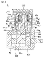
- Fig. 2 is a sectional view of the high-pressure pump 8 as seen from its side
- Fig. 3 is a sectional view of the high-pressure pump 8 as seen from its front.
- the high-pressure pump 8 has a cam chamber 81a formed at the lower end portion of a pump housing 81.
- a cam shaft 82 that is powered by a crank shaft not shown and rotates at the same rpm as that of the crank shaft, is inserted in the cam chamber 81a, and a pair of cams 82a, 82a is formed on the cam shaft 82 axially with a given space between them.
- the cams 82a are formed by three-crest cams so as to perform three upstrokes (discharge strokes of high-pressure fuel associated with rise of plungers 84 described later) per rotation of the cam shaft 82, with the cam lift phases of the individual cams 82a, 82a being 120 degrees apart.
- each of the cams 82a, 82a causes each of the cams 82a, 82a to perform three upstrokes per rotation of the cam shaft 82, resulting in a total of six upstrokes being carried out. Since the crank shaft makes two rotations per engine cycle, the cam shaft 82 also makes two rotations per cycle in synchronization therewith, resulting in 12 upstrokes being carried out per cycle. That is, fuel is pressure-fed 12 times to the common rail 2. As described above, since the engine according to the present embodiment is a six-cylinder engine, fuel pressure feed is performed in two steps to the common rail 2 during the time period from fuel injection to one cylinder to fuel injection to another cylinder. Two-step fuel pressure feed is intended to minimize the peak drive torque value needed to rotate the cam shaft 82.
- the peak drive torque value for rotating the cam shaft 82 becomes considerably high, resulting in a tendency toward larger loss of power for driving the high-pressure pump 8.
- fuel is pressure-fed in two separate steps in the present embodiment. It is to be noted that the peak drive torque value can be further suppressed if fuel is pressure-fed in three or more separate steps.
- a pair of plunger barrels 83, 83 is provided inside the upper portion of the pump housing 81, with the plungers 84, 84 inserted in the lower halves of the plunger barrels 83, 83.
- discharge valves 85a accommodated in valve housings 85, 85 and check valves 85b inserted in the discharge valves 85a.
- the plungers 84 are cylindrical in shape and fitted into the plunger barrels 83 so as to be free to make reciprocating motion in the vertical direction in the figure.
- a plunger chamber 86 is formed between the upper end surface of each of the plungers 84 and each of the valve housings 85.
- the plunger chamber 86 communicates with the upper space of the check valve 85b (space between the check valve 85b and the discharge valve 85a) accommodated inside the valve housing 85.
- the plunger chamber 86 is under low pressure when the plunger 84 is at the bottom dead center (the state of the plunger 84 on the right in Fig. 2 ), whereas the plunger chamber 86 is under high pressure when the plunger 84 is at the top dead center (the state of the plunger 84 on the left in Fig. 2 ).
- a slider 84b biased downward by a return spring 84a.
- the slider 84b has a cam roller 84c.
- the cam roller 84c slidingly contacts the outer surface of the cam 82a. Therefore, as the cam 82a rotates as a result of rotation of the cam shaft 82, the plunger 84 makes vertical reciprocating motion via the cam roller 84c and the slider 84b.
- the reciprocating stroke of the plunger 84 is determined by the difference of height of the cam 82a.
- the fuel pipe 7 extending from the fuel tank 4 communicates with a fuel introducing path 87 that is formed spanning from the pump housing 81 and the plunger barrel 83 to the valve housing 85.
- the inner pressure of the fuel introducing path 87 acts on the lower end of the check valve 85b within the valve housing 85. It is to be noted that downward biasing force acts on the check valve 85b and the discharge valve 85a by return springs 85c and 85d.
- crank angle identification device combines two capabilities: crank angle detection capability (capability referred to as “crank angle detection means” in the present invention) and cylinder number discrimination capability (capability referred to as “cylinder number judgment (discrimination) means” in the present invention).
- Fig. 4 is a functional block diagram showing a schematic configuration of a crank angle identification device 100
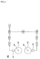
- Fig. 5 is a configuration diagram schematically showing first and second detection means in Fig. 4 .
- 101 and 102 are respectively an engine crank shaft and a cam shaft for inlet and outlet valves, and the cam shaft 102 is designed to be rotated by a mechanism not shown synchronously with the crank shaft 101 at a 1:2 speed reducing ratio.
- the crank shaft 101 is provided with first signal detection means 111 for obtaining first and second detection signals for every predetermined angle related to the rotation of the crank shaft 101.
- the first signal detection means 111 are provided with a crank shaft synchronous rotating body 112 that is connected, for integral rotation, to and rotates synchronously with the crank shaft 101, a plurality of protrusions 112a,... each provided at every given angle along the outer perimeter of the crank shaft synchronous rotating body 112 and an electromagnetic pickup type first detector 113.
- the protrusions 112a of the crank shaft synchronous rotating body 112 are protruded radially outward every 6° crank angle, with an extremely small space between each of the protrusions 112a, 112a and its adjacent protrusion 112a - the space that roughly matches the circumferential width of the protrusion 112a, and two of the protrusions 112a, 112a are continually missing (these missing protrusions are referred to as missing protrusions 112b) before a crank angle reference position A (refer to Fig. 6 ). In this case, although the protrusions 112a,...
- the first detection signal for every predetermined angle is a short-interval detection signal every 6° crank angle that is output each time the protrusion 112a is detected along the circumference of the crank shaft synchronous rotating body 112.
- the signal is detected 58 times when the crank shaft synchronous rotating body 112 makes one rotation.
- the second detection signal for every predetermined angle is a long-interval detection signal that detects the two missing protrusions 112b that are continually missing along the circumference of the crank shaft synchronous rotating body 112. The signal is detected only once when the crank shaft synchronous rotating body 112 makes one rotation.
- the cam shaft 102 is provided with a second signal detection means 121 for obtaining third and fourth detection signals for every predetermined angle related to the rotation of the cam shaft 102.
- the second signal detection means 121 are provided with a cam shaft synchronous rotating body 122 that is connected, for integral rotation, to the end of and rotates synchronously with the cam shaft 102, a plurality of protrusions 122a,... each provided at every given angle along the outer perimeter of the cam shaft synchronous rotating body 122 and an electromagnetic pickup type second detector 123.
- the protrusions 122a of the cam shaft synchronous rotating body 122 are protruded radially outward at positions roughly corresponding to intervals of 60° cam angle along the circumference of the cam shaft synchronous rotating body 122.
- a single protrusion 122b is protruded before a cam angle reference position B and more specifically 6° cam angle away from and before the protrusion 122a of the cam angle reference position B.
- the six protrusions 122a,..., the number corresponding to the number of engine cylinders, are protruded along the circumference of the cam shaft synchronous rotating body 112.
- the third detection signal for every predetermined angle is a constant-interval detection signal corresponding to each cylinder that is output each time the protrusion 122a is detected along the circumference of the cam shaft synchronous rotating body 122.
- the signal is detected six times when the cam shaft synchronous rotating body 122 makes one rotation.
- the fourth detection signal for every predetermined angle is a short-interval double-pulse specified detection signal that is continually detected twice because of the protrusion 122a of the cam angle reference position B and the protrusion 122b that is protruded therebefore.
- the signal is detected only once (double pulse) when the cam shaft synchronous rotating body 122 makes one rotation. In this case, as shown in Fig. 6(a), and Fig.
- the detection signals (electromagnetic pickup output signals) detected by the first detector 113 or second detector 123 are amplified by amplification means first and then converted to rectangular pulse signals by waveform signal forming means, both means in the signal detection means 111 or 121.
- Figs. 6(c) and 7(c) and Figs. 6(d) and 7(d) show the outputs of the amplification means and the waveform signal forming means, respectively. These pulse signals correspond respectively to the protrusions 112a, 122a and 122b.
- 131 is first timer means as first measurement means, and the first timer means 131 measure, in response to output from the first detector 113, the time interval between occurrences of the first and second detection signals obtained based on the crank shaft synchronous rotating body 112.
- 132 is second timer means as second measurement means, and the second timer means 132 measure, in response to output from the second detector 123, the time interval between occurrences of the third and fourth detection signals obtained based on the cam shaft synchronous rotating body 122.
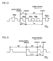
- the first determining means 133 compare, in response to output from the first timer means 131, a time interval between occurrences of the present and previous detection signals detected by the first timer means 131 - a time interval Tm between occurrences of the two detection signals spanning from the protrusion 112a, 112a to its adjacent one - with an immediately previous time interval between occurrences of the previous detection signal and the previous before previous detection signal - a time interval Tm-1 between occurrences of the two detection signals spanning from the protrusion 112a, 112a to its adjacent one, determining whether the detection signal detected by the first timer means 131 is the first detection signal for every predetermined angle (detection signal every 6° crank angle) or the second detection signal for every predetermined angle (specified detection signal for detecting the missing protrusions 112b once per rotation).
- the first determining means 133 compare the time interval Tm and the immediately previous time interval Tm-1 between occurrences of the detection signals detected by the first timer means 131, determining that the present detection signal is the second detection signal for every predetermined angle (specified detection signal by the missing protrusions 112b) when the relationship of 2 ⁇ Tm/Tm-1 ⁇ 4 is satisfied.
- "2" and "4" that prescribe the range of Tm/Tm-1 are variables that can be varied depending on the engine operating conditions such as engine load, whether or not the engine has just started or acceleration/deceleration.
- 134 is second determining means, and as shown in Fig. 9 , the second determining means 134 compare, in response to output from the second timer means 132, a time interval between occurrences of the present and previous detection signals detected by the second timer means 132 - a time interval Tn between occurrences of the two detection signals spanning from the protrusion 122a, 122a to its adjacent one - with an immediately previous time interval between occurrences of the previous detection signal and the previous before previous detection signal - a time interval Tn-1 between occurrences of the two detection signals spanning from the protrusion 122a, 122a to its adjacent one, determining whether the detection signal detected by the second timer means 132 is the third detection signal for every predetermined angle (cylinder detection signal corresponding to each cylinder) or the fourth detection signal for every predetermined angle (double-pulse specified detection signal once per rotation).
- the second determining means 134 compare the time interval Tn and the immediately previous time interval Tn-1 between occurrences of the detection signals detected by the second timer means 132, determining that the present detection signal is the fourth detection signal for every predetermined angle (double-pulse specified detection signal) when the relationship of 0.1 ⁇ Tn/Tn-1 ⁇ 0.5 is satisfied.
- "0.1" and "0.5" that prescribe the range of Tn/Tn-1 are variables that can be varied depending on the engine operating conditions such as engine load, whether or not the engine has just started or acceleration/deceleration.
- 135 is count reference determining means, and the count reference determining means 135 determine, in response to outputs from the first and second determining means 133 and 134, that the occurrence timing of the first detection signal measured first by the first timer means 131 is a crank angle count reference A (crank angle reference position A) as shown in Fig. 10 , when the detection signal is judged by the first determining means 133 as the second detection signal for every predetermined angle (specified detection signal once per rotation) and by the second determining means 134 as the fourth detection signal for every predetermined angle (double-pulse specified detection signal) within a given angle (e.g., within 30°) of the crank shaft synchronous rotating body 112.
- crank angle count reference A (crank angle reference position A) is, as shown in Fig. 6A , stipulated to be the leading edge position of the pulse signal (the protrusion 112a) in the rotation direction of the crank shaft synchronous rotating body 112.
- the cam angle reference position B is, as shown in Fig. 7A , stipulated to be the leading edge position of the pulse signal (the protrusion 122a) in the rotation direction of the cam shaft synchronous rotating body 122.
- 141 is count means, and the count means 141 count, in response to output from the first determining means 133, occurrences of the first detection signal based on the crank shaft synchronous rotating body 112 each time the signal occurs.
- the count means 141 are designed to be reset when the number of occurrences of the first signal based on the crank shaft synchronous rotating body 112 reaches a given value.
- the given value for resetting the count means 141 is determined to be when the number of occurrences of the first signal based on the crank shaft synchronous rotating body 112 reaches a value equivalent to the rotation of a cylinder, namely, "20.”
- the count means 141 are reset when "18" -- value derived by subtracting two pulses - is reached.
- the cylinder number is successively updated (1->2->3->4->5->6->1->---) each time the count means 141 are reset. That is, the cylinder number to be recognized is successively updated when the number of occurrences of the detection signal based on the crank shaft synchronous rotating body 112 reaches "20" or "18.”
- crank angle and cylinder number information allows for crank angle and cylinder number information to be obtained, thus transmitting these pieces of information to the controller 12.
- the fuel pressure detector comprises the crank angle identification device 100 having the cylinder number discrimination capability and the crank angle detection capability described earlier, the pressure sensor 13 as pressure detection means and storage means 14 provided in the controller 12.
- the storage means 14, provided in the controller 12, store a cylinder number, a crank angle and a common rail fuel pressure, in response to output signals from the crank angle identification device 100 having the cylinder number discrimination capability and the crank angle detection capability and the pressure sensor 13, by associating these pieces of information together. More specifically, the pressure sensor 13 detects the common rail fuel pressure every 6° crank angle and sends the pressure detection result to the storage means 14.
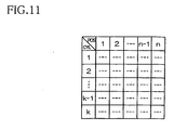
- the storage means 14 create a table as shown in Fig. 11 by associating the pressure detection data (common rail fuel pressure data) with the cylinder number and the crank angle and store the table.
- This provides unified control over common rail fuel pressure data according to the conditions of the individual cylinders (stroke position such as piston top or bottom dead center) and the crank shaft's crank angle.
- Each time pressure detection data is detected the data is written successively to the corresponding block in the table (data write area in the table corresponding to the recognized cylinder number and crank angle (pulse count) at the timing of pressure detection), thus updating the table.
- a new table may be successively created each time the crank shaft makes two rotations. That is, tables are created one after another.
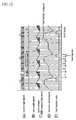
- Fig. 12 is a timing chart showing various waveforms detected as a result of engine operation.
- (A) in the figure is a crank angle signal waveform transmitted by the crank angle sensor (constituted by the crank angle identification device 100)
- (B) is a cam angle signal waveform transmitted by the cam angle sensor (constituted by the crank angle identification device 100) (the waveforms are approximately identical to those in Fig. 10 ).
- (C) illustrates the phase shift status of the high-pressure pump 8, with the shaded areas representing the pressure feed steps. That is, one cycle (one crest) of the waveform (C) represents the discharge operation of high-pressure fuel by one reciprocating motion of the plunger 84 of the high-pressure pump 8.
- (D) is a waveform showing the changes in the common rail fuel pressure obtained by plotting the common rail fuel pressure detected every given crank angle (6°). That is, the pressure sensor 13 detects the common rail fuel pressure at the trailing edges of the waveform (A) pulse (detection conducted similarly when the missing protrusions 112b pass), and the waveform (D) is created based on the pressure detection results.
- (E) is a waveform illustrating the fuel injection ratio that represents the injection timings of the injectors 1.
- the common rail fuel pressure repeatedly undergoes changes, reaching a given fuel injection pressure after two pressure feed steps and then slipping suddenly as a result of fuel injection by one of the injectors 1 (configuration already described for performing the two pressure feed steps).
- a first pressure feed step (step indicated by I in Fig. 12 ) after fuel injection by the injector 1 is called the first pressure feed step
- a second pressure feed step (step indicated by III in Fig. 12 ) is called the second pressure feed step
- a non-pressure feed step between the first and second pressure feed steps is referred to as an intermediate pressure step (step indicated by II in Fig. 12 )
- a non-pressure feed step between the end of the second pressure feed step and the start of fuel injection (step indicated by IV in Fig. 12 ) is referred to as an injection pressure step.
- the common rail fuel pressure gradually rises in the first and second pressure feed steps I and III, but abruptly declines at the fuel injection timing as a result of fuel injection by the injector 1.
- the common rail fuel pressure remains relatively stable in the intermediate pressure step II and the injection pressure step IV.
- the pressure sensor 13 detects the common rail fuel pressure every 6° crank angle as described above, namely, synchronously with the trailing edges of the crank angle signal (A) pulse in Fig. 12 and sends the pressure detection results to the storage means 14, that creates the table shown in Fig. 11 by associating the cylinder number, the crank angle and the common rail fuel pressure with one another and stores the table.
- FIG. 13 A flowchart of Fig. 13 illustrates this operation. That is, when the engine operation starts, the pressure sensor 13 detects the common rail fuel pressure each time the crank angle rotates 6° from the initial angle (Step ST1), whereas the storage means 14 store the pressure detection result (sampling results) in buffer by associating the result with the cylinder number and the crank angle (Step ST2). This operation is repeated each time the crank angle rotates 6°, thus creating the aforementioned table based on the stored data.
- Fig. 14 is a flowchart illustrating the count operation for deciding conditions for controlling the common rail fuel pressure using the above table.
- Step ST11 it is judged in Step ST11 whether the present crank angle POS is the correct timing for referencing the common rail fuel pressure during the detection operation of the common rail fuel pressure.
- the process proceeds to Step ST12.
- the timing for referencing the pressure is, for example, set at a timing preceding from the timing at which to execute the control conditions obtained from the count - the timing that takes into account the amount of time it takes for pressure data extraction and count.
- Step ST21 the aforementioned table is referenced, extracting the common rail fuel pressure corresponding to the cylinder number CYL and the given crank angle POS and sending the data to a count buffer.
- count buffer count is performed, for example, to find conditions to obtain the optimal common rail fuel pressure.
- the fuel pressure detector According to the present embodiment, it is possible according to the fuel pressure detector according to the present embodiment to acquire, with high accuracy, and store detection data on the common rail fuel pressure - data that constitutes basic data for obtaining the optimal fuel injection conditions (fuel injection time and amount) according to the engine rpm, engine load, etc. - through detection of the common rail fuel pressure every given crank angle and tabulation of the data.
- This makes it possible to readily recognize a variation pattern of the common rail fuel pressure according to the cylinder number and the crank angle as a result of the tabulation.
- a control program can be built with precision for properly controlling the common rail fuel pressure and the fuel injection time and amount associated therewith, thus allowing highly efficient control over engine operation.
- the detection timing for the common rail fuel pressure is stipulated to be every given crank angle, ensuring excellent data reproducibility and thereby allowing acquisition of data preferred for controlling the common rail fuel pressure and the engine.
- the first modification is intended to provide data discrimination means 15 for discriminating, from among data stored in the storage means 14, data related to the common rail fuel pressure in the step preceding the final pressure feed step (the second pressure feed step III), that is, during the time period from after fuel pressure feed in the first pressure feed step I until before fuel pressure feed in the next step (namely, the second pressure feed step III).
- the data discrimination means 15 can discriminate, in the present embodiment, data detected in the intermediate pressure step II - a non-pressure feed step between the first and second pressure feed steps I and III - and extract the data as necessary. More specifically, data may be discriminated as the data detected in the intermediate pressure step II by recognizing variations in the common rail fuel pressure. Alternatively, data may be discriminated as the data detected in the intermediate pressure step II by comparing the data with waveforms such as the crank angle signal (A), the cam angle signal (B) and the high-pressure pump 8 phase (C).
- data discriminated and extracted by the data discrimination means 15 is that which is detected when the common rail fuel pressure is under the fuel injection pressure and when fuel is not pressure-fed into the common rail 2 (the intermediate pressure step II). That is, since the data is detected when the common rail fuel pressure is under the fuel injection pressure, it is the data detected at a timing falling outside those timings when the common rail fuel pressure is likely to change suddenly as a result of execution of fuel injection. Besides, since fuel is not being pressure-fed, this data is extracted as the data detected at a timing when variations in the common rail fuel pressure are relatively small. This allows extraction of common rail fuel pressure data detected with high accuracy
- the pressure data detected at this timing may be the data in the process of or after fuel injection and therefore cannot be claimed to be desired data. This is the reason why the present modification extracts the pressure data at a timing falling outside those timings when the common rail fuel pressure is likely to change suddenly as a result of execution of fuel injection, thus allowing acquisition of highly reliable pressure data.
- fuel is pressure-fed to the common rail 2 in two steps, namely, the first and second pressure feed steps I and III, and data detected in the intermediate pressure step II, the non-pressure feed step between the first and second pressure feed steps I and III, is subject to discrimination and extraction by the data discrimination means 15. That is, this makes it possible to extract the pressure data that is detected immediately before the final pressure feed step when the common rail fuel pressure is relatively high (close to the fuel injection pressure). For this reason, in estimating the fuel injection pressure based on common rail fuel pressure data detected at a timing when variations are relatively small, it is possible to acquire common rail fuel pressure data detected at the most reliable timing (timing when the common rail fuel pressure is closest to the fuel injection pressure).
- the aforementioned embodiment and the first modification are designed to detect the common rail fuel pressure every given crank angle.
- the present modification is instead designed to detect the common rail fuel pressure at each elapse of a given time.
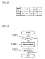
- the common rail fuel pressure is detected by the pressure sensor 13 every 5msec during the engine operation, with the detection data sent to the storage means for creation of the table shown in Fig. 15 .
- the time intervals for pressure detection timing are not limited to 5msec and may be set arbitrarily, it is preferred, to properly recognize the variation pattern of the common rail fuel pressure, that the time intervals be about several tens of ⁇ sec to several msec.
- n-time sampling data namely, common rail fuel pressure data detected over the time period of 5xn (msec).
- the present modification also allows for acquisition with high accuracy and storage of detection data on the common rail fuel pressure - data that constitutes basic data for obtaining optimal fuel injection conditions (fuel injection time and amount) according to the engine rpm, engine load, etc.
- the detection start timing for the common rail fuel pressure at each elapse of a given time is set to begin based on the crank angle, it is possible to acquire data based on temporal changes in the fuel pressure in the common rail 2 only over a necessary period of time. This ensures reduced detection load for the control device and provides improved compatibility between acquired and desired data.
- the detection timing of the common rail fuel pressure is stipulated to be each elapse of a given time, thus allowing acquisition of data preferred for analysing physical phenomena during the engine operation. For example, it is possible to obtain the common rail fuel pressure as the data appropriate for analyzing the status of occurrence of pulsation arising in the common rail.
- the detected common rail fuel pressure data is tabulated.
- the common rail fuel pressure detected every given crank angle e.g., every 6°
- the data for controlling the common rail fuel pressure without tabulating the data.
- the common rail fuel pressure is detected in the step preceding the final pressure feed step (the second pressure feed step III), namely, during the time period from after fuel pressure feed in the first pressure feed step I until before fuel pressure feed in the next step (namely, the second pressure feed step III), and the pressure detection data is used as the data for controlling the common rail fuel pressure.
- Fig. 16 is a flowchart illustrating the pressure detection operation in the present modification.
- a determining is made in Step ST21 as to whether the crank angle has reached a given crank angle, and when that crank angle is reached, the pressure sensor 13 detects the common rail fuel pressure in Step ST22 (execution of pressure sampling).
- the common rail fuel pressure is controlled (e.g., controlling the high-pressure pump 8) using the detected common rail fuel pressure data as the data for controlling the common rail fuel pressure.
- the common rail fuel pressure is detected when the common rail fuel pressure is under the fuel injection pressure and also when fuel is not being pressure-fed into the common rail 2 (the intermediate pressure step II). That is, the common rail fuel pressure is detected at a timing when pressure variations are relatively stable, thus providing improved detection accuracy for the common rail fuel pressure.
- the pulse signal detection may be conducted at the pulse leading or trailing edges. Further, the pulse signal detection may be carried out at any position in the pulse.
- the fuel pressure detector according to the present invention for the common rail type fuel injection apparatus and the common rail type fuel injection apparatus equipped with the fuel pressure detector are designed, in collecting common rail fuel pressure data during the engine operation, to prescribe sampling timings for fuel pressure data by detecting the common rail fuel pressure every given crank angle or at each elapse of a given time, making them effective for ensuring improved detection data accuracy and providing improved use value of the detection data. It is therefore possible according to the present invention to readily recognize a variation pattern of the common rail fuel pressure according to a cylinder number and a crank angle and provide improved detection data accuracy for the common rail fuel pressure. This makes it possible to build with precision a control program for properly controlling the common rail fuel pressure and the fuel injection time and amount associated therewith, thus allowing highly efficient control over the engine operation.
Landscapes
- Engineering & Computer Science (AREA)
- Chemical & Material Sciences (AREA)
- Combustion & Propulsion (AREA)
- Mechanical Engineering (AREA)
- General Engineering & Computer Science (AREA)
- Physics & Mathematics (AREA)
- Fluid Mechanics (AREA)
- Combined Controls Of Internal Combustion Engines (AREA)
- Electrical Control Of Air Or Fuel Supplied To Internal-Combustion Engine (AREA)
- Fuel-Injection Apparatus (AREA)
Applications Claiming Priority (3)
| Application Number | Priority Date | Filing Date | Title |
|---|---|---|---|
| JP2002285873A JP3965098B2 (ja) | 2002-09-30 | 2002-09-30 | コモンレール式燃料噴射装置の燃料圧力検出装置及びその燃料圧力検出装置を備えたコモンレール式燃料噴射装置 |
| JP2002285873 | 2002-09-30 | ||
| PCT/JP2003/012292 WO2004031561A1 (ja) | 2002-09-30 | 2003-09-25 | コモンレール式燃料噴射装置の燃料圧力検出装置及びその燃料圧力検出装置を備えたコモンレール式燃料噴射装置 |
Publications (3)
| Publication Number | Publication Date |
|---|---|
| EP1548262A1 EP1548262A1 (en) | 2005-06-29 |
| EP1548262A4 EP1548262A4 (en) | 2005-12-07 |
| EP1548262B1 true EP1548262B1 (en) | 2009-09-09 |
Family
ID=32063565
Family Applications (1)
| Application Number | Title | Priority Date | Filing Date |
|---|---|---|---|
| EP03799137A Expired - Lifetime EP1548262B1 (en) | 2002-09-30 | 2003-09-25 | Fuel pressure detection device for common rail type fuel injection device, and common rail type fuel injection device having such fuel pressure detection device |
Country Status (9)
| Country | Link |
|---|---|
| US (1) | US7267106B2 (ja) |
| EP (1) | EP1548262B1 (ja) |
| JP (1) | JP3965098B2 (ja) |
| KR (1) | KR20050051582A (ja) |
| CN (1) | CN100357584C (ja) |
| AT (1) | ATE442521T1 (ja) |
| AU (1) | AU2003266634A1 (ja) |
| DE (1) | DE60329203D1 (ja) |
| WO (1) | WO2004031561A1 (ja) |
Families Citing this family (37)
| Publication number | Priority date | Publication date | Assignee | Title |
|---|---|---|---|---|
| US20030012985A1 (en) | 1998-08-03 | 2003-01-16 | Mcalister Roy E. | Pressure energy conversion systems |
| JP2006029088A (ja) * | 2004-07-12 | 2006-02-02 | Yanmar Co Ltd | 蓄圧式燃料噴射装置及びその蓄圧式燃料噴射装置を備えた内燃機関 |
| JP4489648B2 (ja) * | 2005-07-20 | 2010-06-23 | 本田技研工業株式会社 | 内燃機関の燃料供給装置 |
| JP4840288B2 (ja) * | 2006-11-14 | 2011-12-21 | 株式会社デンソー | 燃料噴射装置及びその調整方法 |
| JP4817383B2 (ja) * | 2006-11-24 | 2011-11-16 | Udトラックス株式会社 | 自動車用燃料噴射装置の検査装置 |
| JP4894492B2 (ja) * | 2006-12-08 | 2012-03-14 | トヨタ自動車株式会社 | 燃料噴射制御装置 |
| EP2133540A4 (en) * | 2007-03-05 | 2013-08-07 | Yanmar Co Ltd | FUEL INJECTION DEVICE FOR DIESEL ENGINE |
| DE102007011654A1 (de) * | 2007-03-09 | 2008-09-11 | Continental Automotive Gmbh | Verfahren und Vorrichtung zur Volumenstromregelung eines Einspritzsystems |
| US8899203B2 (en) * | 2007-06-22 | 2014-12-02 | Ford Global Technologies, Llc | Engine position identification |
| JP4424395B2 (ja) * | 2007-08-31 | 2010-03-03 | 株式会社デンソー | 内燃機関の燃料噴射制御装置 |
| DE602007009109D1 (de) * | 2007-09-21 | 2010-10-21 | Magneti Marelli Spa | Steuerverfahren für ein Common-Rail Einspritzsystem mit einem Absperrventil zur Steuerung des Flusses einer Hochdruckbrennstoffpumpe |
| DE602007005260D1 (de) * | 2007-09-26 | 2010-04-22 | Magneti Marelli Spa | Verfahren zur Steuerung eines Common-Rail-Direkteinspritzungsystems mit einer Hochdruckkraftstoffpumpe |
| JP4492664B2 (ja) * | 2007-09-28 | 2010-06-30 | 株式会社デンソー | 燃料供給量推定装置及び燃料圧送噴射システム |
| JP5055103B2 (ja) * | 2007-12-14 | 2012-10-24 | 三菱重工業株式会社 | 高圧ポンプ用カムのトップ位置検出装置 |
| US7980120B2 (en) * | 2008-12-12 | 2011-07-19 | GM Global Technology Operations LLC | Fuel injector diagnostic system and method for direct injection engine |
| US7938101B2 (en) * | 2009-02-11 | 2011-05-10 | GM Global Technology Operations LLC | Adaptive control of fuel delivery in direct injection engines |
| US8265853B2 (en) * | 2009-10-09 | 2012-09-11 | GM Global Technology Operations LLC | Cylinder pressure measurement system and method |
| JP5556209B2 (ja) * | 2010-02-05 | 2014-07-23 | 株式会社デンソー | 高圧燃料ポンプの基準時期算出装置 |
| CN102182602B (zh) * | 2011-02-01 | 2013-05-15 | 潍柴动力股份有限公司 | 在高压共轨系统中基于曲轴转角来测量轨压的方法和装置 |
| DE102011103988A1 (de) * | 2011-06-10 | 2012-12-13 | Mtu Friedrichshafen Gmbh | Verfahren zur Raildruckregelung |
| JP2014025359A (ja) * | 2012-07-24 | 2014-02-06 | Ihi Shibaura Machinery Corp | ディーゼルエンジン |
| US8838367B1 (en) * | 2013-03-12 | 2014-09-16 | Mcalister Technologies, Llc | Rotational sensor and controller |
| WO2014144581A1 (en) | 2013-03-15 | 2014-09-18 | Mcalister Technologies, Llc | Internal combustion engine and associated systems and methods |
| US9255560B2 (en) | 2013-03-15 | 2016-02-09 | Mcalister Technologies, Llc | Regenerative intensifier and associated systems and methods |
| DE102014201789B4 (de) * | 2014-01-31 | 2022-01-05 | Bayerische Motoren Werke Aktiengesellschaft | Antriebssystem einer Kraftstoff-Hochdruckpumpe, Kraftstoff- Hochdruckpumpen-Baugruppe sowie Verbrennungsmotor |
| DE102014208558A1 (de) * | 2014-05-07 | 2015-11-12 | Robert Bosch Gmbh | Einsspritzsystem sowie Verfahren zum Betreiben eines Einsspritzsystems |
| DE102014217560B3 (de) * | 2014-09-03 | 2015-11-12 | Continental Automotive Gmbh | Verfahren und Vorrichtung zur Verbesserung der in den Zylindern einer Brennkraftmaschine erfolgenden Verbrennungsvorgänge |
| DE102015220859A1 (de) * | 2015-10-26 | 2017-04-27 | Robert Bosch Gmbh | Verfahren zum Bestimmen der Anbaulage einer Pumpe |
| SE540744C2 (en) * | 2015-11-27 | 2018-10-30 | Scania Cv Ab | Method and system for determining pressure in a fuel accumulator tank of an engine |
| GB2554917B (en) * | 2016-10-14 | 2020-04-08 | Delphi Tech Ip Ltd | Method to determine fuel pump phasing |
| US10190525B2 (en) * | 2017-02-16 | 2019-01-29 | GM Global Technology Operations LLC | Method of calculating an angular position of a crankshaft during a fuel injection event |
| CN108930622B (zh) * | 2017-05-23 | 2021-02-19 | 宝山钢铁股份有限公司 | 移动式柴油机高压分路压力综合诊断装置和诊断方法 |
| DE102017217113A1 (de) * | 2017-09-26 | 2019-03-28 | Robert Bosch Gmbh | Verfahren zum Betreiben eines Verbrennungsmotors und elektronisches Steuergerät für einen Verbrennungsmotor |
| FR3072124B1 (fr) * | 2017-10-09 | 2019-10-04 | Continental Automotive France | Procede et systeme de detection du sens de rotation d'un moteur de vehicule |
| JP7120081B2 (ja) * | 2019-03-01 | 2022-08-17 | 株式会社デンソー | 燃料噴射ポンプ |
| JP7331776B2 (ja) * | 2020-05-21 | 2023-08-23 | トヨタ自動車株式会社 | 燃圧推定システム、データ解析装置、燃料供給装置の制御装置 |
| JP7294235B2 (ja) * | 2020-05-21 | 2023-06-20 | トヨタ自動車株式会社 | 燃圧推定システム、データ解析装置、燃料供給装置の制御装置 |
Family Cites Families (17)
| Publication number | Priority date | Publication date | Assignee | Title |
|---|---|---|---|---|
| JP3235201B2 (ja) | 1992-08-26 | 2001-12-04 | 株式会社デンソー | コモンレール圧検出装置 |
| US5313924A (en) * | 1993-03-08 | 1994-05-24 | Chrysler Corporation | Fuel injection system and method for a diesel or stratified charge engine |
| US5678521A (en) * | 1993-05-06 | 1997-10-21 | Cummins Engine Company, Inc. | System and methods for electronic control of an accumulator fuel system |
| US5564391A (en) * | 1993-06-16 | 1996-10-15 | Caterpillar Inc. | Electronic control for a hydraulic-actuator unit injector fuel system and method for operating same |
| JPH07122422A (ja) | 1993-10-27 | 1995-05-12 | Toshiba Corp | 超電導マグネットの冷却システム |
| JP3834918B2 (ja) * | 1997-03-04 | 2006-10-18 | いすゞ自動車株式会社 | エンジンの燃料噴射方法及びその装置 |
| JP3713918B2 (ja) * | 1997-08-29 | 2005-11-09 | いすゞ自動車株式会社 | エンジンの燃料噴射方法及びその装置 |
| JPH11101149A (ja) * | 1997-09-26 | 1999-04-13 | Isuzu Motors Ltd | エンジンの燃料噴射方法及びその装置 |
| JP2000018078A (ja) * | 1998-06-30 | 2000-01-18 | Isuzu Motors Ltd | コモンレール圧力の圧力降下開始時期特定方法,並びにエンジンの燃料噴射方法及びその装置 |
| JP3903600B2 (ja) | 1998-07-03 | 2007-04-11 | 株式会社デンソー | 蓄圧式燃料噴射装置 |
| JP2000265896A (ja) * | 1999-03-17 | 2000-09-26 | Toyota Motor Corp | 高圧燃料噴射装置の異常判定方法 |
| JP4158272B2 (ja) * | 1999-03-26 | 2008-10-01 | トヨタ自動車株式会社 | 高圧燃料噴射系の異常判定方法 |
| US6516782B1 (en) * | 1999-05-27 | 2003-02-11 | Detroit Diesel Corporation | System and method for controlling fuel injections |
| GB0104215D0 (en) * | 2001-02-21 | 2001-04-11 | Delphi Tech Inc | Control method |
| JP4627603B2 (ja) * | 2001-03-15 | 2011-02-09 | 日立オートモティブシステムズ株式会社 | 燃料供給装置 |
| JP4464575B2 (ja) | 2001-03-27 | 2010-05-19 | スズキ株式会社 | 2サイクルエンジンの排気時期制御装置 |
| US6694953B2 (en) * | 2002-01-02 | 2004-02-24 | Caterpillar Inc | Utilization of a rail pressure predictor model in controlling a common rail fuel injection system |
-
2002
- 2002-09-30 JP JP2002285873A patent/JP3965098B2/ja not_active Expired - Fee Related
-
2003
- 2003-09-25 US US10/506,793 patent/US7267106B2/en not_active Expired - Fee Related
- 2003-09-25 EP EP03799137A patent/EP1548262B1/en not_active Expired - Lifetime
- 2003-09-25 WO PCT/JP2003/012292 patent/WO2004031561A1/ja active Application Filing
- 2003-09-25 KR KR1020047014261A patent/KR20050051582A/ko not_active Application Discontinuation
- 2003-09-25 CN CNB038057832A patent/CN100357584C/zh not_active Expired - Fee Related
- 2003-09-25 AU AU2003266634A patent/AU2003266634A1/en not_active Abandoned
- 2003-09-25 AT AT03799137T patent/ATE442521T1/de not_active IP Right Cessation
- 2003-09-25 DE DE60329203T patent/DE60329203D1/de not_active Expired - Fee Related
Also Published As
| Publication number | Publication date |
|---|---|
| WO2004031561A1 (ja) | 2004-04-15 |
| CN1643243A (zh) | 2005-07-20 |
| EP1548262A1 (en) | 2005-06-29 |
| AU2003266634A1 (en) | 2004-04-23 |
| DE60329203D1 (de) | 2009-10-22 |
| ATE442521T1 (de) | 2009-09-15 |
| EP1548262A4 (en) | 2005-12-07 |
| JP3965098B2 (ja) | 2007-08-22 |
| US20050103311A1 (en) | 2005-05-19 |
| CN100357584C (zh) | 2007-12-26 |
| JP2004124716A (ja) | 2004-04-22 |
| US7267106B2 (en) | 2007-09-11 |
| KR20050051582A (ko) | 2005-06-01 |
Similar Documents
| Publication | Publication Date | Title |
|---|---|---|
| EP1548262B1 (en) | Fuel pressure detection device for common rail type fuel injection device, and common rail type fuel injection device having such fuel pressure detection device | |
| CN101377180B (zh) | 用于内燃机的燃料喷射控制器 | |
| EP2378101B1 (en) | Fuel injection device and adjustment method thereof | |
| JP4026368B2 (ja) | 蓄圧式燃料噴射装置 | |
| US7500471B2 (en) | Pressure accumulation-type fuel injection device and internal combustion engine provided with this pressure accumulation-type fuel injection device | |
| CN107013353B (zh) | 内燃机的控制系统 | |
| JP4479764B2 (ja) | 燃料噴射制御装置およびそれを用いた燃料噴射システム | |
| WO1998035150A1 (fr) | Procede et dispositif d'injection de carburant d'un moteur | |
| US7032582B2 (en) | Injection control system of internal combustion engine | |
| CN107013352B (zh) | 内燃机的控制装置 | |
| CN101440765A (zh) | 配备有高压燃料泵的共轨型直喷系统的控制方法 | |
| EP1429015A2 (en) | Signal processing filter and control device for common rail pressure | |
| EP1925803B1 (en) | Fuel injection device and adjustment method thereof | |
| CN102644519B (zh) | 用于内燃引擎的燃料喷射系统 | |
| CN101328841B (zh) | 起动内燃发动机的方法和系统 | |
| JP3798615B2 (ja) | 高圧燃料供給系の異常検出装置 | |
| CN110062843B (zh) | 用于估计机动车辆发动机中的燃料喷射系统的高压泵的上止点的方法 | |
| EP1811161A1 (en) | Method of diagnosing the operation of a cam profile shifting system. | |
| JP2000282929A (ja) | 燃料噴射装置 | |
| JP4269484B2 (ja) | 蓄圧式燃料噴射装置 | |
| JP2586566B2 (ja) | 燃料噴射装置 | |
| JPH09264181A (ja) | 燃料噴射制御装置 | |
| JP7054363B2 (ja) | 燃料ポンプの制御装置 | |
| JP4788700B2 (ja) | 燃料噴射制御装置およびそれを用いた燃料噴射システム | |
| EP0790396A2 (en) | Apparatus for detecting misfires in an electronic controlled diesel engine |
Legal Events
| Date | Code | Title | Description |
|---|---|---|---|
| PUAI | Public reference made under article 153(3) epc to a published international application that has entered the european phase |
Free format text: ORIGINAL CODE: 0009012 |
|
| 17P | Request for examination filed |
Effective date: 20040908 |
|
| AK | Designated contracting states |
Kind code of ref document: A1 Designated state(s): AT BE BG CH CY CZ DE DK EE ES FI FR GB GR HU IE IT LI LU MC NL PT RO SE SI SK TR |
|
| AX | Request for extension of the european patent |
Extension state: AL LT LV MK |
|
| A4 | Supplementary search report drawn up and despatched |
Effective date: 20051021 |
|
| RIC1 | Information provided on ipc code assigned before grant |
Ipc: 7F 02D 45/00 A Ipc: 7F 02D 41/00 B Ipc: 7F 02M 47/00 B |
|
| DAX | Request for extension of the european patent (deleted) | ||
| GRAP | Despatch of communication of intention to grant a patent |
Free format text: ORIGINAL CODE: EPIDOSNIGR1 |
|
| GRAS | Grant fee paid |
Free format text: ORIGINAL CODE: EPIDOSNIGR3 |
|
| GRAA | (expected) grant |
Free format text: ORIGINAL CODE: 0009210 |
|
| AK | Designated contracting states |
Kind code of ref document: B1 Designated state(s): AT BE BG CH CY CZ DE DK EE ES FI FR GB GR HU IE IT LI LU MC NL PT RO SE SI SK TR |
|
| REG | Reference to a national code |
Ref country code: GB Ref legal event code: FG4D |
|
| REG | Reference to a national code |
Ref country code: CH Ref legal event code: EP |
|
| REG | Reference to a national code |
Ref country code: IE Ref legal event code: FG4D |
|
| REF | Corresponds to: |
Ref document number: 60329203 Country of ref document: DE Date of ref document: 20091022 Kind code of ref document: P |
|
| PG25 | Lapsed in a contracting state [announced via postgrant information from national office to epo] |
Ref country code: SE Free format text: LAPSE BECAUSE OF FAILURE TO SUBMIT A TRANSLATION OF THE DESCRIPTION OR TO PAY THE FEE WITHIN THE PRESCRIBED TIME-LIMIT Effective date: 20090909 Ref country code: FI Free format text: LAPSE BECAUSE OF FAILURE TO SUBMIT A TRANSLATION OF THE DESCRIPTION OR TO PAY THE FEE WITHIN THE PRESCRIBED TIME-LIMIT Effective date: 20090909 |
|
| NLV1 | Nl: lapsed or annulled due to failure to fulfill the requirements of art. 29p and 29m of the patents act | ||
| PG25 | Lapsed in a contracting state [announced via postgrant information from national office to epo] |
Ref country code: NL Free format text: LAPSE BECAUSE OF FAILURE TO SUBMIT A TRANSLATION OF THE DESCRIPTION OR TO PAY THE FEE WITHIN THE PRESCRIBED TIME-LIMIT Effective date: 20090909 Ref country code: SI Free format text: LAPSE BECAUSE OF FAILURE TO SUBMIT A TRANSLATION OF THE DESCRIPTION OR TO PAY THE FEE WITHIN THE PRESCRIBED TIME-LIMIT Effective date: 20090909 |
|
| PG25 | Lapsed in a contracting state [announced via postgrant information from national office to epo] |
Ref country code: CY Free format text: LAPSE BECAUSE OF FAILURE TO SUBMIT A TRANSLATION OF THE DESCRIPTION OR TO PAY THE FEE WITHIN THE PRESCRIBED TIME-LIMIT Effective date: 20090909 |
|
| PG25 | Lapsed in a contracting state [announced via postgrant information from national office to epo] |
Ref country code: ES Free format text: LAPSE BECAUSE OF FAILURE TO SUBMIT A TRANSLATION OF THE DESCRIPTION OR TO PAY THE FEE WITHIN THE PRESCRIBED TIME-LIMIT Effective date: 20091220 Ref country code: EE Free format text: LAPSE BECAUSE OF FAILURE TO SUBMIT A TRANSLATION OF THE DESCRIPTION OR TO PAY THE FEE WITHIN THE PRESCRIBED TIME-LIMIT Effective date: 20090909 Ref country code: RO Free format text: LAPSE BECAUSE OF FAILURE TO SUBMIT A TRANSLATION OF THE DESCRIPTION OR TO PAY THE FEE WITHIN THE PRESCRIBED TIME-LIMIT Effective date: 20090909 Ref country code: PT Free format text: LAPSE BECAUSE OF FAILURE TO SUBMIT A TRANSLATION OF THE DESCRIPTION OR TO PAY THE FEE WITHIN THE PRESCRIBED TIME-LIMIT Effective date: 20100111 Ref country code: MC Free format text: LAPSE BECAUSE OF NON-PAYMENT OF DUE FEES Effective date: 20090930 Ref country code: CZ Free format text: LAPSE BECAUSE OF FAILURE TO SUBMIT A TRANSLATION OF THE DESCRIPTION OR TO PAY THE FEE WITHIN THE PRESCRIBED TIME-LIMIT Effective date: 20090909 |
|
| REG | Reference to a national code |
Ref country code: CH Ref legal event code: PL |
|
| PG25 | Lapsed in a contracting state [announced via postgrant information from national office to epo] |
Ref country code: SK Free format text: LAPSE BECAUSE OF FAILURE TO SUBMIT A TRANSLATION OF THE DESCRIPTION OR TO PAY THE FEE WITHIN THE PRESCRIBED TIME-LIMIT Effective date: 20090909 |
|
| PG25 | Lapsed in a contracting state [announced via postgrant information from national office to epo] |
Ref country code: BE Free format text: LAPSE BECAUSE OF FAILURE TO SUBMIT A TRANSLATION OF THE DESCRIPTION OR TO PAY THE FEE WITHIN THE PRESCRIBED TIME-LIMIT Effective date: 20090909 Ref country code: AT Free format text: LAPSE BECAUSE OF FAILURE TO SUBMIT A TRANSLATION OF THE DESCRIPTION OR TO PAY THE FEE WITHIN THE PRESCRIBED TIME-LIMIT Effective date: 20090909 |
|
| PLBE | No opposition filed within time limit |
Free format text: ORIGINAL CODE: 0009261 |
|
| STAA | Information on the status of an ep patent application or granted ep patent |
Free format text: STATUS: NO OPPOSITION FILED WITHIN TIME LIMIT |
|
| PG25 | Lapsed in a contracting state [announced via postgrant information from national office to epo] |
Ref country code: DE Free format text: LAPSE BECAUSE OF NON-PAYMENT OF DUE FEES Effective date: 20100401 Ref country code: IE Free format text: LAPSE BECAUSE OF NON-PAYMENT OF DUE FEES Effective date: 20090925 Ref country code: DK Free format text: LAPSE BECAUSE OF FAILURE TO SUBMIT A TRANSLATION OF THE DESCRIPTION OR TO PAY THE FEE WITHIN THE PRESCRIBED TIME-LIMIT Effective date: 20090909 |
|
| 26N | No opposition filed |
Effective date: 20100610 |
|
| GBPC | Gb: european patent ceased through non-payment of renewal fee |
Effective date: 20091209 |
|
| PG25 | Lapsed in a contracting state [announced via postgrant information from national office to epo] |
Ref country code: CH Free format text: LAPSE BECAUSE OF NON-PAYMENT OF DUE FEES Effective date: 20090930 Ref country code: LI Free format text: LAPSE BECAUSE OF NON-PAYMENT OF DUE FEES Effective date: 20090930 Ref country code: GR Free format text: LAPSE BECAUSE OF FAILURE TO SUBMIT A TRANSLATION OF THE DESCRIPTION OR TO PAY THE FEE WITHIN THE PRESCRIBED TIME-LIMIT Effective date: 20091210 |
|
| PG25 | Lapsed in a contracting state [announced via postgrant information from national office to epo] |
Ref country code: GB Free format text: LAPSE BECAUSE OF NON-PAYMENT OF DUE FEES Effective date: 20091209 |
|
| PG25 | Lapsed in a contracting state [announced via postgrant information from national office to epo] |
Ref country code: IT Free format text: LAPSE BECAUSE OF FAILURE TO SUBMIT A TRANSLATION OF THE DESCRIPTION OR TO PAY THE FEE WITHIN THE PRESCRIBED TIME-LIMIT Effective date: 20090909 Ref country code: BG Free format text: LAPSE BECAUSE OF FAILURE TO SUBMIT A TRANSLATION OF THE DESCRIPTION OR TO PAY THE FEE WITHIN THE PRESCRIBED TIME-LIMIT Effective date: 20090930 |
|
| PG25 | Lapsed in a contracting state [announced via postgrant information from national office to epo] |
Ref country code: LU Free format text: LAPSE BECAUSE OF NON-PAYMENT OF DUE FEES Effective date: 20090925 |
|
| REG | Reference to a national code |
Ref country code: FR Ref legal event code: ST Effective date: 20110502 |
|
| PG25 | Lapsed in a contracting state [announced via postgrant information from national office to epo] |
Ref country code: HU Free format text: LAPSE BECAUSE OF FAILURE TO SUBMIT A TRANSLATION OF THE DESCRIPTION OR TO PAY THE FEE WITHIN THE PRESCRIBED TIME-LIMIT Effective date: 20100310 |
|
| PG25 | Lapsed in a contracting state [announced via postgrant information from national office to epo] |
Ref country code: FR Free format text: LAPSE BECAUSE OF NON-PAYMENT OF DUE FEES Effective date: 20091109 |
|
| PG25 | Lapsed in a contracting state [announced via postgrant information from national office to epo] |
Ref country code: TR Free format text: LAPSE BECAUSE OF FAILURE TO SUBMIT A TRANSLATION OF THE DESCRIPTION OR TO PAY THE FEE WITHIN THE PRESCRIBED TIME-LIMIT Effective date: 20090909 |