EP1547896A2 - Verriegelungseinrichtung für Türen an Fahrzeugen des öffentlichen Personen-Nah- und Fernverkehrs - Google Patents
Verriegelungseinrichtung für Türen an Fahrzeugen des öffentlichen Personen-Nah- und Fernverkehrs Download PDFInfo
- Publication number
- EP1547896A2 EP1547896A2 EP04029411A EP04029411A EP1547896A2 EP 1547896 A2 EP1547896 A2 EP 1547896A2 EP 04029411 A EP04029411 A EP 04029411A EP 04029411 A EP04029411 A EP 04029411A EP 1547896 A2 EP1547896 A2 EP 1547896A2
- Authority
- EP
- European Patent Office
- Prior art keywords
- door
- locking device
- valve
- control
- locking
- Prior art date
- Legal status (The legal status is an assumption and is not a legal conclusion. Google has not performed a legal analysis and makes no representation as to the accuracy of the status listed.)
- Withdrawn
Links
Images


Classifications
-
- E—FIXED CONSTRUCTIONS
- E05—LOCKS; KEYS; WINDOW OR DOOR FITTINGS; SAFES
- E05B—LOCKS; ACCESSORIES THEREFOR; HANDCUFFS
- E05B51/00—Operating or controlling locks or other fastening devices by other non-mechanical means
- E05B51/02—Operating or controlling locks or other fastening devices by other non-mechanical means by pneumatic or hydraulic means
-
- B—PERFORMING OPERATIONS; TRANSPORTING
- B61—RAILWAYS
- B61D—BODY DETAILS OR KINDS OF RAILWAY VEHICLES
- B61D19/00—Door arrangements specially adapted for rail vehicles
- B61D19/02—Door arrangements specially adapted for rail vehicles for carriages
Definitions
- the invention relates to a locking device for doors Public transport vehicles, the by means of a door control device actuated by a door control device be opened and closed.
- Such doors are as swing doors and sliding doors well known.
- the door operating device can thereby pneumatically or electrically operated and receives their control in general as electrical Drive signals issued by a door control device become.
- the invention is based on the object, a locking device for doors the above and in the preamble of claim 1 specified type, in particular as additional locking can be used, which is automatically and centrally controlled and by which the doors can be locked securely while driving, so that a violent or independent opening is prevented.
- each door leaf during the drive through preferably a plurality of locking devices the in different places of the door leaf can be effective to lock.
- the locking and unlocking of the locking devices may be from the door operator or one of these downstream Door control valve to be controlled. Furthermore, it is easier Way to achieve that upon actuation of a emergency valve unlocking the locking devices is effected.
- the locking device according to the invention is both pneumatic as well as electrically operated doors can be used, and
- the locking devices can be pneumatic, hydraulic or electrically operated.
- these pneumatic cylinders opposite to, for example, the door operator representing working cylinder can be made small, can be achieved that to control the opening movement of the door and for controlling the unlocking of the locking devices the same, for example, electrical, control signal can serve as the Smaller pneumatic cylinder respond faster, and thus in In this case, the unlocking of the locking devices completed is before the opening movement of the door begins.
- Fig. 1 shows a highly schematic representation of a hinged door an otherwise not shown vehicle of the public People-Nah- and -fern Strukturs from inside the vehicle seen. It has a door leaf 1, the pivotable in a only in Fig. 3 indicated door frame 1.2 is suspended, and a usual Door closing device 1.1. The pneumatically operated door operator and the elsewhere arranged electrical Door control device are not shown.
- the door is with a locking device provided, which in the illustrated embodiment has four locking devices 2.1 to 2.4, the are each arranged in the corner regions of the door panel 1.
- Each of the Locking devices 2.1 to 2.4 consists of a pneumatic cylinder and a locking element, in the direction of arrows S1 to S4 can be moved into a locking position in which it continues in described in more detail below the door leaf with the door frame 1.2 locked.
- the pneumatic cylinders are connected via a supply line 3 and Branching lines 3.1 to 3.4 supplied with compressed air.
- Fig. 3 shows the arrangement and effect of the locking device 2.1.
- the connected to the branched supply line 3.1 pneumatic cylinder 11.1 includes a retractable against spring force piston which carries the locking element 11 at its outer end.
- the pneumatic cylinder 11.1 is arranged directly adjacent to the outer edge of the door leaf 1, so that when the piston is extended, the locking element 11 is located in the dot-dash line position.
- the pneumatic cylinder 11.1 is, as indicated in Fig.
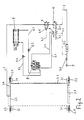
- the locking devices 2.1 supplied to 2.4 from a compressed air source 5 compressed air.
- a check valve 5.2 is initially turned on and on then a solenoid valve 4, through which the compressed air supply line 3 can be vented and vented.
- the control input 4.1 of Solenoid valve 4 is connected via a control line 4.2 with the not shown Door control device connected, fed from which control signals become.
- a second, mechanically actuated valve 6 is turned on, the actuating element 6.1 is mechanically coupled to a valve 7, which means an emergency valve 7.1 is actuated.
- the valve 7 is connected via a pressure air supply line 5.3, which via a branch 5.1 to the compressed air source. 5 is connected, compressed air supplied, which in the in Fig. 2 shown Valve position via a line 7.2 the door control valve. 8 is fed via lines 8.2 and 8.3, in each of which Throttle check valves 8.3 and 8.4 are turned on, with the two Ends of a working cylinder 9 is connected, which part of the door operating device is.
- the door control valve 8 is not specifically shown Way electrically connected to the door control device, from the it receives the control signals for opening and closing the door.
- a also connected to the door control valve 8 compensation pressure line 7.3 is vented in the position shown in Fig. 2 of the valve 7.
- the solenoid valve 4 When closing the door will after closing the closing of the door control device, the solenoid valve 4 is controlled such that the Compressed air supply line 3 is supplied with compressed air and the locking devices 2.1 to 2.4 are brought into the locked position.
- the compressed air supply line 3 at the solenoid valve 4 vented, and due to the rapid response of the pneumatic cylinder the locking devices 2.1 to 2.4 are these unlocked before the actual opening movement of the door from the working cylinder 9 is started from.
- Fig. 4 shows a variant of the drive circuit, wherein the solenoid valve 4 'not from the door control device but from the door control valve 8 'is driven forth.
- the Components of Fig. 2 correspond, with the same reference numerals and marked with an apostrophe line. Not shown in Fig. 4 Components have the same arrangement as in FIG. 2.
Landscapes
- Engineering & Computer Science (AREA)
- Mechanical Engineering (AREA)
- Lock And Its Accessories (AREA)
- Power-Operated Mechanisms For Wings (AREA)
Abstract
Description
dass bei seiner Beaufschlagung mit dem Arbeitsdruck über die Zuleitung 3 bzw. 3.1 das Riegelelement 11 in die Verriegelungsstellung bewegt wird und bei einer Entlüftung der Zuleitung 3 der Pneumatikzylinder unter Federkraft zurückfährt und dadurch das Verriegelungselement 11 in die Entriegelungsstellung zurückbewegt wird. Wie aus Fig. 3 zu entnehmen, greift das Riegelelement 11 in der strichpunktiert eingezeichneten Verriegelungsstellung durch eine Öffnung 10.1 einer Schließkulisse 10, hinter ein Schließblech 10.2 ein, so dass in dieser Stellung das Türblatt 1 mit dem Türrahmen 1.2 verriegelt ist. Zur Abdichtung des Spaltes zwischen Türblatt 1 und Türrahmen 1.2 in diesem Bereich dienen mit der Schließkulisse 10 verbundene Dichtungslippen 10.3 und 10.4 sowie eine mit dem Türblatt 1 verbundene Dichtungslippe 10.5.
Claims (10)
- Verriegelungseinrichtung für Türen an Fahrzeugen des öffentlichen Personen-Nah- und -Fernverkehrs, die mittels einer von einer Türsteuereinrichtung angesteuerten Türbetätigungsvorrichtung geöffnet und geschlossen werden, dadurch gekennzeichnet, dass jedes Türblatt (1) mindestens eine Verriegelungsvorrichtung (2.1 bis 2.4) aufweist mit einem pneumatisch, hydraulisch oder elektrisch betätigbaren Riegelelement (11), das im Türblatt (1) oder im Türrahmen angeordnet ist und mit einem im Türrahmen (1.2) oder im Türblatt angeordneten Gegenelement (10-10.2) zusammenwirkt, wobei die Ansteuerung des Riegelelements (11) über ein Steuerelement (4) erfolgt, dessen Ansteuereingang (4.1) ein Steuersignal zugeführt wird, welches die Verriegelung und Entriegelung der Verriegelungsvorrichtung auslöst.
- Verriegelungseinrichtung nach Anspruch 1, dadurch gekennzeichnet, dass die Verriegelungsvorrichtung (2.1 bis 2.4) pneumatisch oder hydraulisch betätigbar ist und das Steuerelement (4) als ansteuerbares Ventil ausgebildet ist, über welches einem Pneumatik- bzw. Hydraulikzylinder das Druckmittel von einer Druckquelle (5) aus zugeführt wird.
- Verriegelungseinrichtung nach Anspruch 1, dadurch gekennzeichnet, dass die Verriegelungsvorrichtung elektrisch betätigbar ist und das Steuerelement als Steuerschalter ausgebildet ist, über welchen einem elektrischen Stellglied elektrische Energie von einer Stromquelle her zugeführt wird.
- Verriegelungseinrichtung nach Anspruch 2, dadurch gekennzeichnet, dass die Verriegelungsvorrichtung (2.1 bis 2.4) pneumatisch betätigbar ist und das ansteuerbare Ventil (4) eine Belüftungs- und eine Entlüftungsstellung aufweist und der Pneumatikzylinder bei Beaufschlagung mit dem Arbeitsdruck in der Belüftungsstellung des Ventils (4) das Riegelelement (11) in die Verriegelungsstellung bewegt und bei Entlüftung unter Einwirkung eines Federelements das Riegelelement (11) in die Entriegelungsstellung zurückbewegt wird.
- Verriegelungseinrichtung nach einem der Ansprüche 1 bis 4, dadurch gekennzeichnet, dass pro Türblatt (1) mehrere Verriegelungsvorrichtungen (2.1 bis 2.4) vorgesehen sind, die an verschiedenen Stellen des Türblatts (1) wirksam sind und die über ein gemeinsames Steuerelement (4) betätigbar sind.
- Verriegelungseinrichtung nach einem der Ansprüche 1 bis 5, dadurch gekennzeichnet, dass jeweils das Riegelelement (11) der Verriegelungsvorrichtung (2.1 bis 2.4) im Türblatt (1) und das Gegenelement (10-10.2) im oder am Türrahmen (1.2) angeordnet sind.
- Verriegelungseinrichtung nach Anspruch 4 und ggf. einem der Ansprüche 5 oder 6, dadurch gekennzeichnet, dass in der Zuleitung (3) von der Druckluftquelle (5) zum Pneumatikzylinder bzw. zu den Pneumatikzylindern in Serie zum ansteuerbaren Ventil (4) ein zweites, von einem Nothahn (7.1) her betätigbares Ventil (6) zur Entlüftung der Zuleitung (3) angeordnet ist.
- Verriegelungseinrichtung nach Anspruch 4 und ggf. einem der Ansprüche 5 bis 7, dadurch gekennzeichnet, dass das ansteuerbare Ventil (4) ein Elektromagnetventil ist und das elektrische Steuersignal von der Türsteuereinrichtung aus zugeführt wird.
- Verriegelungseinrichtung nach Anspruch 4 und 7 und ggf. einem der Ansprüche 5, 6 oder 8 bei einer pneumatisch betätigbaren Türbetätigungsvorrichtung mit einem an eine Druckluftquelle (5) angeschlossenen Türsteuerventil (8), an welches ein in beiden Bewegungsrichtungen beaufschlagbarer Arbeitszylinder (9) zum Öffnen und Schließen der Tür angeschlossen ist, dadurch gekennzeichnet, dass der Nothahn (7.1) ein manuell betätigbares, in der Zuleitung von der Druckluftquelle (5) zum Türsteuerventil (8) angeordnetes Be-/Entlüftungsventil (7) steuert, das mechanisch mit dem zweiten Ventil (6) zur Entlüftung der Zuleitung (3) zum Pneumatikzylinder gekoppelt ist.
- Verriegelungseinrichtung nach Anspruch 4 und ggf. einem der Ansprüche 5 bis 9 bei einer pneumatisch betätigbaren Türbetätigungsvorrichtung mit einem an eine Druckluftquelle (5) angeschlossenen Türsteuerventil (8'), an welches ein in beiden Bewegungsrichtungen beaufschlagbarer Arbeitszylinder (9') zum Öffnen und Schließen der Tür angeschlossen ist, dadurch gekennzeichnet, dass das ansteuerbare Ventil (4') ein Magnetventil ist, dessen Ansteuereingang (4.1') an einen mit dem Türsteuerventil (8') verbundenen Druckluftschalter (8.5') angeschlossen ist, der bei der Stellung "Tür auf" des Türsteuerventils (8') ein elektrisches Signal gibt, durch welches das ansteuerbare Ventil (4') in die Entlüftungsstellung gesteuert wird.
Applications Claiming Priority (2)
| Application Number | Priority Date | Filing Date | Title |
|---|---|---|---|
| DE20320028U DE20320028U1 (de) | 2003-12-24 | 2003-12-24 | Verriegelungseinrichtung für Türen an Fahrzeugen des öffentlichen Personen-Nah- und Fernverkehrs |
| DE20320028U | 2003-12-24 |
Publications (2)
| Publication Number | Publication Date |
|---|---|
| EP1547896A2 true EP1547896A2 (de) | 2005-06-29 |
| EP1547896A3 EP1547896A3 (de) | 2007-11-14 |
Family
ID=34530448
Family Applications (1)
| Application Number | Title | Priority Date | Filing Date |
|---|---|---|---|
| EP04029411A Withdrawn EP1547896A3 (de) | 2003-12-24 | 2004-12-11 | Verriegelungseinrichtung für Türen an Fahrzeugen des öffentlichen Personen-Nah- und Fernverkehrs |
Country Status (2)
| Country | Link |
|---|---|
| EP (1) | EP1547896A3 (de) |
| DE (1) | DE20320028U1 (de) |
Cited By (2)
| Publication number | Priority date | Publication date | Assignee | Title |
|---|---|---|---|---|
| DE102009005591A1 (de) | 2009-01-21 | 2009-09-17 | Daimler Ag | Schaltungsanordnung für eine Betätigung einer Tür |
| EP1860262A3 (de) * | 2006-05-22 | 2009-12-09 | Ultimate Transportation Equipment GmbH | Verriegelungsvorrichtung für eine Fahrzeugtür |
Family Cites Families (9)
| Publication number | Priority date | Publication date | Assignee | Title |
|---|---|---|---|---|
| AT377322B (de) * | 1982-01-22 | 1985-03-11 | Vmw Ranshofen Berndorf Ag | Automatischer oeffnungsmechanismus fuer drehoder falttueren, insbesondere von fahrzeugen |
| DE3502752A1 (de) * | 1985-01-28 | 1986-07-31 | Knorr-Bremse AG, 8000 München | Steuereinrichtung fuer pneumatisch betaetigbare tueren |
| DE3742058C2 (de) * | 1987-12-11 | 1996-10-31 | Bosch Gmbh Robert | Pneumatische Türbetätigungseinrichtung |
| DE3912778C2 (de) * | 1989-04-19 | 1997-08-28 | Bosch Gmbh Robert | Türbetätigungseinrichtung |
| FR2669074B1 (fr) * | 1990-11-09 | 1995-06-30 | Renault Vehicules Ind | Dispositif d'actionnement et de verrouillage des portes pour vehicules industriels destines au transport de personnes. |
| US5341598A (en) * | 1992-05-08 | 1994-08-30 | Mark Iv Transportation Products Corporation | Power door drive and door support having motor operated locks |
| DE4230888A1 (de) * | 1992-09-16 | 1994-03-17 | Horst Dipl Ing Goldbach | Schwenkschiebetür für Fahrzeuge |
| DE4315617A1 (de) * | 1993-05-11 | 1994-11-17 | Bode & Co Geb | Ausschwenkbare Schiebetür für Fahrzeuge, insbesondere Fahrzeuge des öffentlichen Personenverkehrs |
| DE10014346C1 (de) * | 2000-03-24 | 2001-03-22 | Daimler Chrysler Ag | Türbetätigungsanlage |
-
2003
- 2003-12-24 DE DE20320028U patent/DE20320028U1/de not_active Expired - Lifetime
-
2004
- 2004-12-11 EP EP04029411A patent/EP1547896A3/de not_active Withdrawn
Cited By (2)
| Publication number | Priority date | Publication date | Assignee | Title |
|---|---|---|---|---|
| EP1860262A3 (de) * | 2006-05-22 | 2009-12-09 | Ultimate Transportation Equipment GmbH | Verriegelungsvorrichtung für eine Fahrzeugtür |
| DE102009005591A1 (de) | 2009-01-21 | 2009-09-17 | Daimler Ag | Schaltungsanordnung für eine Betätigung einer Tür |
Also Published As
| Publication number | Publication date |
|---|---|
| EP1547896A3 (de) | 2007-11-14 |
| DE20320028U1 (de) | 2005-05-12 |
Similar Documents
| Publication | Publication Date | Title |
|---|---|---|
| DE3519203A1 (de) | Stellvorrichtung fuer eine tuer eines kraftfahrzeugs | |
| DE102010002625A1 (de) | Hydraulische Stelleinrichtung für einen Türflügel eines Omnibusses | |
| DE3400753A1 (de) | Aussenschwingtuer fuer fahrzeuge und ihre betaetigungsvorrichtung | |
| DE102021006214A1 (de) | Kraftfahrzeug-Türanordnung | |
| AT410010B (de) | Hydraulische betätigungsanordnung und hydraulisch sperrbares rückschlagventil | |
| AT408208B (de) | Anordnung zur hydraulischen betätigung eines bewegten teils an fahrzeugen, insbesondere eines verdecks, eines heckdeckels, einer abdeckklappe oder dgl. | |
| DE202010013611U1 (de) | Kraftfahrzeugschloss | |
| DE19725677A1 (de) | Fenster, Tür od. dgl. an Wohnwagen, Wohnmobilen oder sonstigen Fahrzeugen | |
| DE3130699C2 (de) | Omnibus mit einer kraftbetätigten Tür | |
| DE102009001227A1 (de) | Heckklappenanordnung für ein Kraftfahrzeug | |
| AT400695B (de) | Anordnung zur hydraulischen betätigung eines fahrzeugverdeckes | |
| DE10014346C1 (de) | Türbetätigungsanlage | |
| EP1547896A2 (de) | Verriegelungseinrichtung für Türen an Fahrzeugen des öffentlichen Personen-Nah- und Fernverkehrs | |
| EP1812671B1 (de) | Kombinierte schliesseinrichtung | |
| EP1072749A2 (de) | Elektromechanischer Antrieb für eine Drehsäule zur Bewegung eines Türflügels einer Innenschwenk- oder Aussenschwingtür an einem Fahrzeug, insbesondere einem öffentlichen Verkehrsmittel | |
| DE3105867C2 (de) | Schaltungsanordnung für druckmittelbetätigte, insbesondere pneumatisch betätigte, Türen in Fahrzeugen, wie Omnibussen, Straßenbahnen o.dgl. | |
| DE19914629A1 (de) | Schließ- und Verriegelungssystem | |
| DE102005061127A1 (de) | Luftfahrzeugtür-Anordnung sowie Luftfahrzeugrumpf mit einer derartigen Luftfahrzeugtür-Anordnung | |
| DE1128323B (de) | Einrichtung zum Betaetigen und Verriegeln mehrerer Schliessvorrichtungen an Kraftfahrzeugen | |
| EP0744516B1 (de) | Veriegelungssystem für eine Tür | |
| AT409399B (de) | Hydraulische betätigungsanordnung | |
| EP1589168A1 (de) | Betätigungsvorrichtung für eine Notentriegelungseinrichtung an Türen für Fahrzeuge des öffentlichen Personen-Nah- und-Fernverkehrs | |
| EP4446535B1 (de) | Integrierte seitliche abdicht- und verriegelungsvorrichtung | |
| DE20307840U1 (de) | Notentriegelungsvorrichtung an einer Schwenkschiebetür für Fahrzeuge, insbesondere Fahrzeuge des öffentlichen Personennahverkehrs | |
| DE102013202801A1 (de) | Einrichtung zur motorischen Betätigung einer Kraftfahrzeug-Türe mit Feststellfunktion |
Legal Events
| Date | Code | Title | Description |
|---|---|---|---|
| PUAI | Public reference made under article 153(3) epc to a published international application that has entered the european phase |
Free format text: ORIGINAL CODE: 0009012 |
|
| AK | Designated contracting states |
Kind code of ref document: A2 Designated state(s): AT BE BG CH CY CZ DE DK EE ES FI FR GB GR HU IE IS IT LI LT LU MC NL PL PT RO SE SI SK TR |
|
| AX | Request for extension of the european patent |
Extension state: AL BA HR LV MK YU |
|
| PUAL | Search report despatched |
Free format text: ORIGINAL CODE: 0009013 |
|
| AK | Designated contracting states |
Kind code of ref document: A3 Designated state(s): AT BE BG CH CY CZ DE DK EE ES FI FR GB GR HU IE IS IT LI LT LU MC NL PL PT RO SE SI SK TR |
|
| AX | Request for extension of the european patent |
Extension state: AL BA HR LV MK YU |
|
| RIC1 | Information provided on ipc code assigned before grant |
Ipc: E05F 15/06 20060101ALI20071010BHEP Ipc: B61D 19/02 20060101AFI20050406BHEP |
|
| AKX | Designation fees paid | ||
| STAA | Information on the status of an ep patent application or granted ep patent |
Free format text: STATUS: THE APPLICATION IS DEEMED TO BE WITHDRAWN |
|
| 18D | Application deemed to be withdrawn |
Effective date: 20080515 |
|
| REG | Reference to a national code |
Ref country code: DE Ref legal event code: 8566 |