EP1545890B1 - Handstempel mit auswechselbaren stempelplatten und stempelplatte für einen handstempel - Google Patents
Handstempel mit auswechselbaren stempelplatten und stempelplatte für einen handstempel Download PDFInfo
- Publication number
- EP1545890B1 EP1545890B1 EP03798818A EP03798818A EP1545890B1 EP 1545890 B1 EP1545890 B1 EP 1545890B1 EP 03798818 A EP03798818 A EP 03798818A EP 03798818 A EP03798818 A EP 03798818A EP 1545890 B1 EP1545890 B1 EP 1545890B1
- Authority
- EP
- European Patent Office
- Prior art keywords
- stamp
- hand
- stamp plate
- grooves
- webs
- Prior art date
- Legal status (The legal status is an assumption and is not a legal conclusion. Google has not performed a legal analysis and makes no representation as to the accuracy of the status listed.)
- Expired - Lifetime
Links
- 229920001971 elastomer Polymers 0.000 claims description 7
- 239000000463 material Substances 0.000 claims description 7
- 239000013013 elastic material Substances 0.000 claims description 6
- 229920003023 plastic Polymers 0.000 claims description 5
- 239000004033 plastic Substances 0.000 claims description 5
- 230000007306 turnover Effects 0.000 claims 2
- 230000000295 complement effect Effects 0.000 description 4
- 238000003780 insertion Methods 0.000 description 2
- 230000037431 insertion Effects 0.000 description 2
- 238000004519 manufacturing process Methods 0.000 description 2
- 244000043261 Hevea brasiliensis Species 0.000 description 1
- 229920000459 Nitrile rubber Polymers 0.000 description 1
- 229920000122 acrylonitrile butadiene styrene Polymers 0.000 description 1
- 238000004026 adhesive bonding Methods 0.000 description 1
- NTXGQCSETZTARF-UHFFFAOYSA-N buta-1,3-diene;prop-2-enenitrile Chemical compound C=CC=C.C=CC#N NTXGQCSETZTARF-UHFFFAOYSA-N 0.000 description 1
- 238000006073 displacement reaction Methods 0.000 description 1
- -1 for example Substances 0.000 description 1
- 238000010409 ironing Methods 0.000 description 1
- 229920003049 isoprene rubber Polymers 0.000 description 1
- 239000002184 metal Substances 0.000 description 1
- 229920003052 natural elastomer Polymers 0.000 description 1
- 229920001194 natural rubber Polymers 0.000 description 1
Images

Classifications
-
- B—PERFORMING OPERATIONS; TRANSPORTING
- B41—PRINTING; LINING MACHINES; TYPEWRITERS; STAMPS
- B41K—STAMPS; STAMPING OR NUMBERING APPARATUS OR DEVICES
- B41K1/00—Portable hand-operated devices without means for supporting or locating the articles to be stamped, i.e. hand stamps; Inking devices or other accessories therefor
- B41K1/02—Portable hand-operated devices without means for supporting or locating the articles to be stamped, i.e. hand stamps; Inking devices or other accessories therefor with one or more flat stamping surfaces having fixed images
- B41K1/04—Portable hand-operated devices without means for supporting or locating the articles to be stamped, i.e. hand stamps; Inking devices or other accessories therefor with one or more flat stamping surfaces having fixed images with multiple stamping surfaces; with stamping surfaces replaceable as a whole
-
- B—PERFORMING OPERATIONS; TRANSPORTING
- B41—PRINTING; LINING MACHINES; TYPEWRITERS; STAMPS
- B41K—STAMPS; STAMPING OR NUMBERING APPARATUS OR DEVICES
- B41K1/00—Portable hand-operated devices without means for supporting or locating the articles to be stamped, i.e. hand stamps; Inking devices or other accessories therefor
- B41K1/36—Details
- B41K1/38—Inking devices; Stamping surfaces
- B41K1/40—Inking devices operated by stamping movement
Definitions
- the invention relates to a self-inking hand stamp with a turning mechanism according to the introductory part of claim 1.
- the invention relates to a stamp plate for such a self-inking hand stamp according to the introductory part of claim 18.
- a generic hand stamp is known in which a plug connection between a stamp plate and stamp plate carrier is provided by means of a recess engaging in a male projection.
- this connector has the disadvantage that the stamp plate is mounted relatively loosely on the punch plate carrier; Therefore, there is a risk that the stamp plate unintentionally releases from the carrier or at least inadvertently twisted relative to the carrier, so that the stamp imprint is not generated in the desired orientation.
- a hand stamp is known in which a polygonal support is provided with undercut grooves are inserted into the shells lengthwise, which in turn contain printing plates, so stamp plates. At the bottom of the groove surveys are provided to secure the shell against displacement.
- the WO 02/058937 A1 describes a self-inking handstamp with a swivel type aggregate which carries both fixed and replaceable stamp types.
- the replaceable stamp types can be used via insertion projections in recesses in the type unit, whereas the fixed stamp types are arranged on a stamp plate on the type unit.
- the stamp plate of this hand stamp is fixedly attached to the stamp plate carrier so that the stamp imprint produced therewith is not variable.
- Another disadvantage is that the replaceable stamp types sit in an opening in the manner of a window, whereby an insertion tool is required to replace the exchangeable stamp types.
- the DE 198 26 762 A1 discloses a stamp for printing a motif on a surface, in particular on the human skin, wherein a motif body is held with a negative of the motif bearing pressure surface via a magnetic connection to the base body of the punch.
- a permanent magnet must be arranged on the base body, which is also provided for positioning with recesses, in the projections of the magnetic Motive body intervene.
- a stamp is known in which a stamp plate is attached to a one-piece with a handle punch plate carrier via a dovetail connection by gluing;
- the stamp plate is inserted with a strip-shaped projection in a dovetail-shaped recess of the punch plate carrier.
- the object of the invention is to provide a self-inking hand stamp or a stamp plate as stated above, wherein the detachable connection between the stamp plate and stamp plate carrier is easy to implement and yet reliable, so that the stamp plate with the stamp plate carrier nonetheless stable, durable and secure against rotation can be connected ,
- the present embodiment with the specified multiple-groove or web structure ensures a secure hold of the stamp plate on Stempelplattenyes (hereinafter briefly carrier), in a simple manner, the total contact surfaces (for a press or snap fit) between the two parts are increased.
- a placement of the stamp plate on the carrier is just as easy to accomplish as a deliberate release of the stamp plate from the carrier, which takes place in the manner of a "peeling".
- a basic idea of the invention is thus to design the mutually complementary engaging parts of the stamp plate or of the carrier in such a way that they give a relatively large overall contact area. This is realized by the mentioned multiple groove or web structures.
- the stamp plate can be connected to the carrier in a snap fit, that is to say in a form-fitting manner, or in a tight fit, that is to say in a force-fitting manner.
- a particularly good, firm hold of the stamp plate on the carrier is achieved in that the groove or web structures are provided substantially over the entire surface of the carrier or the stamp plate. It is therefore convenient, e.g. on the stamp plate to provide an edge-side recess which comprises the entire edge or can be provided only in places. Such a recess is useful in terms of receiving a corresponding circumferential projection of the stamp carrier.
- the grooves and the webs have a rectangular, in particular square cross-section.
- the grooves and the webs may have a cross-section engaging behind each other. This can be realized for example by a trapezoidal or rhomboid cross section.
- other undercuts e.g. with a dovetailed cross section or with curved side surfaces.
- the groove or web structures mutually parallel grooves and mutually parallel webs have.
- grooves or webs are the same width.
- the grooves or webs are each the same height or deep.
- a preferred feature according to the invention is also to provide transverse grooves which intersect the grooves and corresponding transverse webs. As a result, an additional fixation and a facilitated alignment of the stamp plate can be provided.
- the carrier made of dimensionally stable Material is made. This ensures easy attachment of the stamp plate on the carrier, since the carrier is not bendable.
- the carrier may be made of metal per se, but preferably it consists of plastic, advantageously of hard plastic, such as ABS plastic.
- the attachment and removal or replacement of the stamp plate is particularly easy to do, because the stamp plate made of elastic material, preferably made of rubber.
- the stamp plate made of elastic material, preferably made of rubber.
- This is advantageously a soft elastic rubber material, such as, for example, rubber based on NR (natural rubber or isoprene rubber) and / or butadiene-acrylonitrile rubber.
- the stamp plate is made of a material that is soft or bendable in relation to the material of the carrier, it is particularly advantageous to provide a friction or snug fit.
- Another preferred feature of the invention is to provide recordings for letters or stamp types on the side facing away from the groove or web structures side of the stamp plate.
- These receptacles are advantageously again provided in groove form, wherein in particular a parallel arrangement of the grooves can be realized.
- the recordings have rounded or bevelled undercuts.
- the shots for simplicity, but also have a rectangular or square cross-section, provided that a sufficient interference fit is secured.
- the letters are made of elastic material, preferably of plastic or rubber. Even if the stamp plate is made of elastic material, the letters may consist of a similar or similar material.
- stamp plate For the frequent use of the stamp plate, it is particularly advantageous if several letters or stamp types are connected to each other. Prefabricated words or word combinations, characters, special characters, whole syllables or also multi-digit numbers in one piece.
- the subject matter of the invention is both a self-inking hand stamp as indicated as well as a stamp plate per se, as indicated, which is then combined with a self-inking hand stamp - yet without a stamp plate but with a matching carrier.
- Fig. 1 is a partially schematic, illustrates a cross-sectionally generally circular self-inking hand stamp 1 in approximately true size in a longitudinal section, which in a conventional per se and therefore not further explained with a self-inking device, with a turning mechanism, (such as in US 4 432 281 A or AT 384 999 B described) is equipped.
- the hand stamp 1 is shown in the rest position in which a stamp plate 3 applied to a stamp plate carrier 2 bears against an ink pad 10, ie the stamp plate 3 is located at the top.
- the stamp 1 further includes a housing 13 and an operating handle with handle 14.
- the carrier 2 has downwardly projecting guide legs 15, on each of which a laterally projecting axis 17 is mounted; the axes 17 engage in guide slots 18, which are provided in the housing 13 of the hand stamp 1, and further protrude in not further illustrated recesses of ironing extensions of the bracket 14.
- the turning axis of the turning mechanism is also in a conventional manner by a pin 16 at the Inside the housing 13 realized in the guide slots or grooves 16 'of Leg 15 of the carrier 2 engage.
- the stamp plate 3 is connected to the carrier 2 via engaging parts in the form of multiple-groove or web structures 4, 5. Furthermore, releasable letters or stamp types 9 used in the stamp plate 3 are shown, wherein type recordings 8 are provided on the side of the stamp plate 3 facing away from the carrier 2. These types 9 are directly on the ink pad 10.
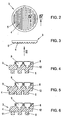
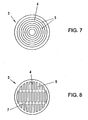
- FIGS. 2, 3 . 7 and 8 show exemplary embodiments of the stamp plate 3, wherein the carrier 2 (not shown) facing side is illustrated in a plan view.
- the grooves 4 and webs 5 are all parallel to each other, wherein the grooves 4 and the webs 5 are all the same width. It is still out Fig. 2 , as well as out Fig. 3 , recognizable that the grooves 4 and the webs 5 are arranged on the entire surface of the stamp plate 3, wherein only a marginal recess is provided to make room for a corresponding circumferential projection of the carrier 2 (see Fig. 1 ) to accomplish.
- the carrier 2 has otherwise complementary grooves or webs.
- FIGS. 7 and 8 Further embodiments of the stamp plate are in FIGS. 7 and 8 shown, wherein the stamp plate 3 according to Fig. 7 Grooves 4 and webs 5 in a concentric arrangement.
- Fig. 8 is a stamp plate 3 similar Fig. 2 shown, with additional transverse grooves or transverse webs 7 are present and produce a kind of grid pattern.
- the stamp plate 3 does not necessarily have to be circular, but may have other shapes such as rectangular or square shapes.
- Fig. 4 shows a schematic cross section of the stamp plate 3 according to Fig. 2 , (Section IV) on a larger scale, the in Fig. 3 shown underside (see arrow II in Fig. 3 ) of the stamp plate 3 is the side with which the stamp plate 3 is mounted on the carrier 2 in a positive fit or snug fit.
- Fig. 4 have the grooves 4 and webs 5 - as in Fig. 3 - a rectangular cross section.
- the grooves 4 and webs 5 are the same width, with one with respect to an axial Symmetrical arrangement is taken center plane, so that the stamp plate 3 can be fixed in two possible orientations on the support 2.
- stamp types 9 on the grooves 4 and webs 5 opposite side of the stamp plate 3 recognizable.
- These stamp types 9 are mounted in receptacles 8 in a fixed but detachable seat, wherein the receptacles 8 for a secure hold of the stamp types 9 in cross-section, for example, dovetailed undercuts 12 have.
- Fig. 5 are provided on the underside of the stamp plate 3 (and corresponding to the top of the carrier, not shown) grooves 4 and 5 webs with different widths and different heights.
Landscapes
- Manufacture Or Reproduction Of Printing Formes (AREA)
- Discharge By Other Means (AREA)
Description
- Die Erfindung betrifft einen Selbstfärbe-Handstempel mit Wendemechanismus gemäß dem einleitenden Teil von Anspruch 1.
- Weiters betrifft die Erfindung eine Stempelplatte für einen solchen Selbstfärbe-Handstempel gemäß dem einleitenden Teil von Anspruch 18.
- Aus der
AT 1240 U1 US 5 809 886 A ist ein gattungsgemäßer Handstempel bekannt, bei welchem eine Steckverbindung zwischen einer Stempelplatte und Stempelplattenträger mit Hilfe eines in eine Ausnehmung eingreifenden Steckvorsprungs vorgesehen ist. Diese Steckverbindung hat jedoch den Nachteil, dass die Stempelplatte auf dem Stempelplattenträger relativ lose angebracht ist; es besteht daher die Gefahr, dass sich die Stempelplatte vom Träger ungewollt löst oder aber zumindest relativ zum Träger unabsichtlich verdreht, so dass der Stempelabdruck nicht in der gewünschten Ausrichtung erzeugt wird. Aus derAT 386 805 B - Die
WO 02/058937 A1 - Die
DE 198 26 762 A1 offenbart einen Stempel zum Aufdrucken eines Motivs auf eine Oberfläche, insbesondere auf die menschliche Haut, wobei ein Motivkörper mit einer das Negativ des Motivs tragenden Druckfläche über eine Magnetverbindung am Grundkörper des Stempels gehalten wird. Hiezu muss ein Permanentmagnet am Grundkörper angeordnet werden, welcher überdies zur Positionierung mit Ausnehmungen versehen ist, in die Vorsprünge des magnetischen Motivkörpers eingreifen. - Aus der
US 2 143 833 A ist ein Stempel bekannt, bei welchem eine Stempelplatte an einem mit einem Griff einteiligen Stempelplattenträger über eine Schwalbenschwanz-Verbindung durch Kleben befestigt wird; im Einzelnen wird die Stempelplatte mit einem leistenförmigen Vorsprung in eine schwalbenschwanzförmige Ausnehmung des Stempelplattenträgers eingeschoben. Eine solche Verbindungsart ist aber bei komplexen Stempelausbildungen, wie jenen mit Wendemechanismus, praktisch nicht möglich. - Aufgabe der Erfindung ist es, einen Selbstfärbe-Handstempel bzw. eine Stempelplatte wie eingangs angegeben zu schaffen, wobei die lösbare Verbindung zwischen Stempelplatte und Stempelplattenträger einfach realisierbar und dennoch zuverlässig ist, sodass die Stempelplatte mit dem Stempelplattenträger nichtsdestoweniger stabil, dauerhaft und verdrehsicher verbunden werden kann.
- Diese Aufgabe wird bei einem Selbstfärbe-Handstempel bzw. bei einer Stempelplatte gemäß der Erfindung wie in den Ansprüchen 1 bzw. 19 definiert gelöst.
- Die vorliegende Ausbildung mit der angegebenen Mehrfach-Rillen- bzw. Stegstruktur gewährleistet einen sicheren Halt der Stempelplatte am Stempelplattenträger (nachstehend kurz Träger), wobei in einfacher Weise die Gesamt-Kontaktflächen (für einen Press- oder Schnappsitz) zwischen den beiden Teilen vergrößert sind. Ein Aufsetzen der Stempelplatte auf den Träger ist dabei ebenso einfach zu bewerkstelligen wie ein gewolltes Lösen der Stempelplatte vom Träger, das in der Art eines "Abschälens" erfolgt.
- Ein Grundgedanke der Erfindung ist somit, die zueinander komplementären Eingriffsteile der Stempelplatte bzw. des Trägers derart zu gestalten, dass sie eine relativ große Gesamt-Kontakt- bzw. Berührungsfläche ergeben. Dies wird durch die angeführten mehrfachen Rillen- bzw. Stegstrukturen realisiert. Die Stempelplatte kann mit dem Träger in einem Schnappsitz, also formschlüssig, oder in einem engen Passsitz, also kraftschlüssig, verbunden werden.
- Durch die relativ große Gesamt-Kontaktfläche ergibt sich auch als weiterer Vorteil der lösbaren Stempelplatte, dass diese leicht gegen eine andere Stempelplatte ausgetauscht werden kann. Beim Anbringen einer (anderen) Stempelplatte auf dem Träger können überraschend die Stege und Rillen problemlos ineinander gesteckt werden, wenn einfach darauf geachtet wird, dass die Rillen bzw. Stege der Stempelplatte bzw. des Trägers parallel zueinander stehen bzw. dass die Ränder der Stempelplatte und des Trägers zueinander ausgerichtet sind.
- Ein besonders guter, fester Halt der Stempelplatte am Träger wird dadurch erzielt, dass die Rillen- bzw. Stegstrukturen im Wesentlichen auf der gesamten Fläche des Trägers bzw. der Stempelplatte vorgesehen sind. Es ist daher aber zweckdienlich, z.B. an der Stempelplatte, eine randseitige Aussparung vorzusehen, die den gesamten Rand umfasst oder aber auch nur stellenweise vorgesehen sein kann. Eine solche Aussparung ist hinsichtlich der Aufnahme eines entsprechenden Umfangs-Vorsprunges des Stempelträgers zweckmäßig.
- Hinsichtlich einer einfachen, kostengünstigen Herstellung und problemlosen Anbringung der Stempelplatte ist es vorteilhaft, wenn die Rillen und die Stege einen rechteckigen, insbesondere quadratischen Querschnitt aufweisen. Alternativ dazu können die Rillen und die Stege einen einander hintergreifenden Querschnitt aufweisen. Dies kann beispielsweise durch einen trapezförmigen oder rhomboiden Querschnitt realisiert sein. Selbstverständlich ist es auch denkbar, andere Hinterschneidungen vorzusehen, z.B. mit einem schwalbenschwanzförmigen Querschnitt oder mit gekrümmten Seitenflächen.
- Aus Gründen einer einfachen und kostengünstigen Fertigung der Stempelplatte bzw. des Trägers ist es von Vorteil, wenn die Rillen- bzw. Stegstrukturen zueinander parallele Rillen und zueinander entsprechend parallele Stege aufweisen.
- In diesem Zusammenhang ist es auch günstig, wenn die Rillen bzw. Stege gleich breit sind.
- Weiters ist es zweckmäßig, wenn die Rillen bzw. Stege jeweils gleich hoch bzw. tief sind. Selbstverständlich ist es aber auch möglich, voneinander unterschiedliche Tiefen der Rillen bzw. Höhen der Stege vorzusehen, um so den Halt der Stempelplatte am Träger - gegebenenfalls bereichsweise - zu steuern.
- Ein bevorzugtes Merkmal gemäß der Erfindung besteht auch darin, Querrillen, welche die Rillen kreuzen, und entsprechende Querstege vorzusehen. Dadurch kann eine zusätzliche Fixierung sowie eine erleichterte Ausrichtung der Stempelplatte vorgesehen werden.
- Für die lösbare Verbindung von Stempelplatte und Träger über Rillen bzw. Stege, unter Ausnutzung eines Pass- bzw. Reibungssitzes, ist es von besonderem Vorteil, wenn der Träger aus formfestem Material hergestellt ist. Dies gewährleistet ein einfaches Anbringen der Stempelplatte auf dem Träger, da der Träger nicht verbiegbar ist. Der Träger kann an sich aus Metall hergestellt sein, vorzugsweise besteht er jedoch aus Kunststoff, vorteilhafterweise aus Hartkunststoff, wie beispielsweise aus ABS-Kunststoff.
- Das Anbringen und Abnehmen bzw. Auswechseln der Stempelplatte ist besonders leicht zu bewerkstelligen, weil die Stempelplatte aus elastischem Material, vorzugsweise aus Kautschuk, hergestellt ist. Dabei handelt es sich vorteilhafterweise um ein weichelastisches Gummimaterial, wie beispielsweise Kautschuk auf Basis NR (Natur-Kautschuk bzw. Isopren-Kautschuk) und/oder Butadien-Acrylnitril-Kautschuk. Da die Stempelplatte aus einem im Verhältnis zum Material des Trägers weichen bzw. biegbaren Material besteht, kann besonders vorteilhaft ein Reibungs- bzw. Passsitz vorgesehen werden.
- Ein weiteres bevorzugtes Merkmal der Erfindung besteht darin, Aufnahmen für Lettern bzw. Stempeltypen an der von den Rillen- bzw. Stegstrukturen abgewandten Seite der Stempelplatte vorzusehen. Diese Aufnahmen sind vorteilhafterweise wieder in Rillenform vorgesehen, wobei insbesondere eine parallele Anordnung der Rillen realisiert sein kann.
- Zur besseren Verbindung, so dass ein ungewolltes Loslösen der Lettern bzw. der Stempeltypen sowie ein guter Sitz derselben an der Stempelplatte sichergestellt ist, ist es zweckdienlich, wenn die Aufnahmen abgerundete oder abgeschrägte Hinterschneidungen aufweisen. Selbstverständlich können die Aufnahmen der Einfachheit halber aber auch einen rechteckigen oder quadratischen Querschnitt aufweisen, sofern ein ausreichender Presssitz gesichert ist.
- Für ein Auswechseln der Lettern, um eigene, flexibel gestaltete Stempelabdrücke zu erhalten, ist es von besonderem Vorteil, wenn die Lettern aus elastischem Material, vorzugsweise aus Kunststoff oder Kautschuk, hergestellt sind. Auch wenn die Stempelplatte aus elastischem Material gefertigt ist, können die Lettern aus einem ähnlichen oder demgleichen Material bestehen.
- Für den oftmaligen Gebrauch der Stempelplatte ist es besonders vorteilhaft, wenn mehrere Lettern bzw. Stempeltypen miteinander verbunden sind. Dabei können vorgefertigte Wörter oder Wortkombinationen, Zeichen, Sonderzeichen, ganze Silben oder auch mehrstellige Zahlen einstückig vorliegen.
- Aus Vorstehendem ergibt sich, dass Gegenstand der Erfindung sowohl ein Selbstfärbe-Handstempel wie angegeben als auch eine Stempelplatte für sich, wie angegeben, ist, die dann mit einem Selbstfärbe-Handstempel - noch ohne Stempelplatte, aber mit passendem Träger - kombiniert wird.
- Die Erfindung wird nachstehend anhand von in der Zeichnung veranschaulichten bevorzugten Ausführungsbeispielen, auf die sie jedoch nicht beschränkt sein soll, noch weiter erläutert. In der Zeichnung zeigen im Einzelnen:
-
Fig. 1 eine schematische, geschnittene Ansicht eines Handstempels mit Selbstfärbeeinrichtung und Wendemechanismus; -
Fig. 2 eine Stempelplatte gemäß der Erfindung in Draufsicht; -
Fig. 3 eine Stempelplatte gemäßFig. 2 in Ansicht; - die
Figuren 4, 5 und 6 Detailschnittansichten verschiedener Ausführungsformen der Stempelplatte gemäß der Linie IV-IV inFig. 2 , zusätzlich mit auswechselbaren Lettern bzw. Stempeltypen; und - die
Figuren 7 und 8 weitere Ausführungsbeispiele der Stempelplatte in Draufsicht. - In
Fig. 1 ist, teilweise schematisch, ein im Querschnitt allgemein kreisförmiger Selbstfärbe-Handstempel 1 in ungefähr wahrer Größe in einem Längsschnitt veranschaulicht, welcher in an sich herkömmlicher und daher hier nicht weiter zu erläuternder Weise mit einer Selbstfärbeeinrichtung, mit einem Wendemechanismus, (etwa in der Art wie inUS 4 432 281 A oderAT 384 999 B - Die Stempelplatte 3 ist mit dem Träger 2 über Eingriffsteile in Form von Mehrfach-Rillen- bzw. Stegstrukturen 4, 5 verbunden. Weiters sind in der Stempelplatte 3 eingesetzte lösbare Lettern bzw. Stempeltypen 9 gezeigt, wobei Typen-Aufnahmen 8 an der vom Träger 2 abgewandten Seite der Stempelplatte 3 vorgesehen sind. Diese Typen 9 liegen direkt am Stempelkissen 10 an.
- Die
Figuren 2, 3 ,7 und 8 zeigen Ausführungsbeispiele der Stempelplatte 3, wobei die dem Träger 2 (nicht gezeigt) zugewandte Seite in einer Draufsicht veranschaulicht ist. InFig. 2 sind die Rillen 4 und Stege 5 alle parallel zueinander, wobei die Rillen 4 und die Stege 5 alle gleich breit sind. Es ist weiters ausFig. 2 , wie auch ausFig. 3 , erkennbar, dass die Rillen 4 und die Stege 5 auf der gesamten Fläche der Stempelplatte 3 angeordnet sind, wobei nur randseitig eine Aussparung vorgesehen ist, um Platz für einen entsprechenden Umfangs-Vorsprung des Trägers 2 (sieheFig. 1 ) zu schaffen. Der Träger 2 hat im Übrigen komplementäre Rillen bzw. Stege. - Weitere Ausführungsbeispiele der Stempelplatte sind in
Fig. 7 und 8 gezeigt, wobei die Stempelplatte 3 gemäßFig. 7 Rillen 4 und Stege 5 in konzentrischer Anordnung aufweist. InFig. 8 ist eine Stempelplatte 3 ähnlichFig. 2 gezeigt, wobei zusätzlich Querrillen oder Querstege 7 vorhanden sind und eine Art Gittermuster erzeugen. - Die Stempelplatte 3 muss nicht notwendigerweise kreisförmig ausgebildet sein, sondern kann auch andere Formen, wie rechteckige oder quadratische Formen aufweisen.
- Zur Verbindung von Stempelplatte 3 und Träger 2 werden diese aneinander gedrückt, wobei die jeweiligen Stege 5 am einen Teil 3 oder 2 in die Nuten des anderen Teils 2 oder 3 gedrückt werden. Die Rillen- und Stegstrukturen auf dem Träger 2 bzw. auf der Stempelplatte 3 sind somit zueinander komplementär.
-
Fig. 4 zeigt einen schematischen Querschnitt der Stempelplatte 3 gemäßFig. 2 , (Schnitt IV) in größerem Maßstab, wobei die inFig. 3 dargestellte Unterseite (siehe Pfeil II inFig. 3 ) der Stempelplatte 3 jene Seite ist, mit welcher die Stempelplatte 3 auf dem Träger 2 in einem Formschluss oder Passsitz angebracht wird. GemäßFig. 4 weisen die Rillen 4 und Stege 5 - wie inFig. 3 - einen rechteckigen Querschnitt auf. Die Rillen 4 und Stege 5 sind gleich breit, wobei auch eine bezüglich einer axialen Mittenebene symmetrische Anordnung getroffen ist, so dass die Stempelplatte 3 in zwei möglichen Ausrichtungen auf dem Träger 2 fixiert werden kann. - In dem in
Fig. 4 veranschaulichten Ausführungsbeispiel sind darüber hinaus - ähnlich wie inFig. 5 und 6 - lösbare Lettern bzw. Stempeltypen 9 an der den Rillen 4 und Stegen 5 gegenüberliegenden Seite der Stempelplatte 3 erkennbar. Diese Stempeltypen 9 sind in Aufnahmen 8 in einem festen, aber lösbaren Sitz angebracht, wobei die Aufnahmen 8 für einen sicheren Halt der Stempeltypen 9 im Querschnitt z.B. schwalbenschwanzförmige Hinterschneidungen 12 aufweisen. - Gemäß
Fig. 5 sind an der Unterseite der Stempelplatte 3 (und entsprechend an der Oberseite des nicht gezeigten Trägers 2) Rillen 4 bzw. Stege 5 mit unterschiedlichen Breiten und unterschiedlichen Höhen vorgesehen. - In
Fig. 6 sind schließlich sich verbreiternde Stege 5 bzw. hinterschnittene Rillen 4 - z.B. mit schwalbenschwanzförmigem Querschnitt - veranschaulicht, wobei die Oberseite des Trägers 2 (inFig. 6 nicht gezeigt) selbstverständlich wiederum komplementär ausgebildet ist.
Claims (18)
- Selbstfärbe-Handstempel (1) mit Wendemechanismus, mit einem Stempelplattenträger (2) und einer Stempelplatte (3) sowie mit Eingriffsteilen am Stempelplattenträger (2) und an der Stempelplatte (3) zu deren direkten lösbaren Verbindung miteinander, dadurch gekennzeichnet, dass die Eingriffsteile durch Mehrfach-Rillen- bzw. -Stegstrukturen (4, 5) gebildet sind, die mit über die gesamten Flächen der einander zugewandten Seiten des Stempelplattenträgers (2) und der Stempelplatte (3) nebeneinander angeordneten Rillen bzw. Stegen gebildet sind, und dass die Stempelplatte (3) aus elastischem Material besteht derart, dass sie in der Art eines Abschälens vom Stempelplattenträger (2) ablösbar ist.
- Handstempel nach Anspruch 1, dadurch gekennzeichnet, dass die Rillen- bzw. Stegstrukturen (4, 5) einen rechteckigen Querschnitt aufweisen.
- Handstempel nach Anspruch 2, dadurch gekennzeichnet, dass die Rillen- bzw. Stegstrukturen (4, 5) einen quadratischen Querschnitt aufweisen.
- Handstempel nach Anspruch 1, dadurch gekennzeichnet, dass die Rillen (4) und die Stege (5) einen einander hintergreifenden Querschnitt aufweisen.
- Handstempel nach Anspruch 4, dadurch gekennzeichnet, dass die Rillen (4) und die Stege (5) einen trapezförmigen Querschnitt aufweisen.
- Handstempel nach einem der Ansprüche 1 bis 5, dadurch gekennzeichnet, dass Rillen- bzw. Stegstrukturen (4, 5) zueinander parallele Rillen (4) und zueinander entsprechend parallele Stege (5) aufweisen.
- Handstempel nach Anspruch 6, dadurch gekennzeichnet, dass die Rillen (4) bzw. Stege (5) gleich breit sind.
- Handstempel nach Anspruch 6 oder 7, dadurch gekennzeichnet, dass die Rillen (4) bzw. Stege (5) gleich hoch sind.
- Handstempel nach einem der Ansprüche 1 bis 8, dadurch gekennzeichnet, dass Querrillen, welche die Rillen (4) kreuzen, und entsprechende Querstege (7) vorgesehen sind.
- Handstempel nach einem der Ansprüche 1 bis 9, dadurch gekennzeichnet, dass der Stempelplattenträger (2) aus formfestem Material hergestellt ist.
- Handstempel nach Anspruch 10, dadurch gekennzeichnet, dass der Stempelplattenträger (2) aus Kunststoff besteht.
- Handstempel nach Anspruch 11, dadurch gekennzeichnet, dass die Stempelplatte (3) aus Kautschuk besteht.
- Handstempel nach einem der Ansprüche 1 bis 12, dadurch gekennzeichnet, dass Aufnahmen (8) für Lettern bzw. Stempeltypen (9) an der von den Rillen- bzw. Stegstrukturen (4, 5) abgewandten Seite der Stempelplatte (3) ausgebildet sind.
- Handstempel nach Anspruch 13, dadurch gekennzeichnet, dass die Lettern bzw. Stempeltypen (9) aus elastischem Material hergestellt sind.
- Handstempel nach Anspruch 14, dadurch gekennzeichnet, dass die Lettern bzw. Stempeltypen (9) aus einem Material, ausgewählt aus der Gruppe bestehend aus Kunststoff oder Kautschuk, bestehen.
- Handstempel nach Anspruch 13 oder 14, dadurch gekennzeichnet, dass mehrere Lettern bzw. Stempeltypen (9) miteinander verbunden sind.
- Handstempel nach Anspruch 13, dadurch gekennzeichnet, dass die Aufnahmen (8) abgerundete Hinterschneidungen (12) aufweisen.
- Stempelplatte (3) für einen Selbstfärbe-Handstempel (1) mit Wendemechanismus, mit Eingriffsteilen an einer mit einem Stempelplattenträger (2) des Handstempels vorgesehenen Fläche, zur lösbaren Verbindung mit dem Stempelplattenträger des Handstempels, dadurch gekennzeichnet, dass die Eingriffsteile durch eine Mehrfach-Rillen- bzw. -Stegstruktur (4, 5) gebildet sind, die mit über die gesamte Fläche der Stempelplatte nebeneinander angeordneten Rillen bzw. Stegen gebildet sind, und dass die Stempelplatte (3) aus elastischem Material besteht derart, dass sie in der Art eines Abschälens von Stempelplattenträger (2) ablösbar ist.
Applications Claiming Priority (3)
| Application Number | Priority Date | Filing Date | Title |
|---|---|---|---|
| AT66202U | 2002-10-04 | ||
| AT0066202U AT6265U1 (de) | 2002-10-04 | 2002-10-04 | Handstempel |
| PCT/AT2003/000269 WO2004030915A1 (de) | 2002-10-04 | 2003-09-10 | Handstempel mit auswechselbaren stempelplatten und stempelplatte für einen handstempel |
Publications (2)
| Publication Number | Publication Date |
|---|---|
| EP1545890A1 EP1545890A1 (de) | 2005-06-29 |
| EP1545890B1 true EP1545890B1 (de) | 2012-10-24 |
Family
ID=3496498
Family Applications (1)
| Application Number | Title | Priority Date | Filing Date |
|---|---|---|---|
| EP03798818A Expired - Lifetime EP1545890B1 (de) | 2002-10-04 | 2003-09-10 | Handstempel mit auswechselbaren stempelplatten und stempelplatte für einen handstempel |
Country Status (6)
| Country | Link |
|---|---|
| US (1) | US20060000374A1 (de) |
| EP (1) | EP1545890B1 (de) |
| AT (1) | AT6265U1 (de) |
| AU (1) | AU2003258350A1 (de) |
| UA (1) | UA81923C2 (de) |
| WO (1) | WO2004030915A1 (de) |
Families Citing this family (20)
| Publication number | Priority date | Publication date | Assignee | Title |
|---|---|---|---|---|
| USD587746S1 (en) | 2008-06-10 | 2009-03-03 | Fiskars Brands, Inc. | Stamping tool |
| US20090301327A1 (en) * | 2008-06-10 | 2009-12-10 | Fiskars Brands, Inc. | Stamping Tool |
| USD629838S1 (en) | 2010-04-14 | 2010-12-28 | Fiskars Brands, Inc. | Stamp roller |
| CA2717256C (en) * | 2010-05-14 | 2018-05-01 | Sterling Marking Products Inc. | Removable print element assembly for a hand printer |
| AT513901B1 (de) | 2013-01-24 | 2018-08-15 | Colop Stempelerzeugung Skopek Gmbh & Co Kg | Montagevorrichtung |
| CN104936790B (zh) | 2013-01-24 | 2017-05-10 | 克罗普压印器制造斯科皮克两合公司 | 回墨印章 |
| AT513898B1 (de) | 2013-01-24 | 2019-01-15 | Colop Stempelerzeugung Skopek Gmbh & Co Kg | Einrichtung zum Führen eines Farbkissenbehälters sowie Selbstfärbestempel |
| AT513897B1 (de) | 2013-01-24 | 2018-05-15 | Colop Stempelerzeugung Skopek Gmbh & Co Kg | Selbstfärbestempel mit einem Stempelgehäuse |
| EP3388247B1 (de) | 2014-01-10 | 2019-08-07 | Trotec Laser GmbH | Bearbeitungssystem für mehrere unterschiedliche werkstücke |
| AT517318B1 (de) * | 2015-06-10 | 2024-07-15 | Trodat Gmbh | Stempel und Abdruckeinheit |
| AT517321A1 (de) | 2015-06-10 | 2016-12-15 | Trodat Gmbh | Stempel |
| USD823378S1 (en) | 2015-06-10 | 2018-07-17 | Trodat Gmbh | Hand stamp |
| AT517328B1 (de) | 2015-06-10 | 2024-06-15 | Trodat Gmbh | Stempel, ein Stempelkissen und eine Verschlusskappe |
| AT517322A1 (de) * | 2015-06-10 | 2016-12-15 | Trodat Gmbh | Stempel und Abdruckeinheit, insbesondere als Ersatzteil für einen Stempel |
| USD803307S1 (en) | 2015-12-10 | 2017-11-21 | Trodat Gmbh | Hand stamp |
| AT518735B1 (de) | 2016-06-09 | 2024-09-15 | Trodat Gmbh | Antriebseinheit, Bandeinheit, Brücke, Mitnehmer und Stempel hierfür |
| AT519177B1 (de) | 2016-10-06 | 2019-04-15 | Trotec Laser Gmbh | Verfahren zum Gravieren, Markieren und/oder Beschriften eines Werkstückes mit |
| CN112208234A (zh) * | 2020-10-19 | 2021-01-12 | 吴万乔 | 一种提高印章效果的物流自动印章装置 |
| CN113370681B (zh) * | 2021-06-10 | 2023-02-10 | 岳晓 | 一种趣味性汉字信息符号密码式印制方法 |
| CN115195313A (zh) * | 2022-05-26 | 2022-10-18 | 郑杰武 | 一种使用方便的财务金融会计用盖章装置 |
Citations (1)
| Publication number | Priority date | Publication date | Assignee | Title |
|---|---|---|---|---|
| AT386805B (de) * | 1986-05-30 | 1988-10-25 | Skopek Karl | Handstempel |
Family Cites Families (18)
| Publication number | Priority date | Publication date | Assignee | Title |
|---|---|---|---|---|
| US2899895A (en) * | 1959-08-18 | Rubber stamp | ||
| US752771A (en) * | 1904-02-23 | Island | ||
| AT3868B (de) | 1900-01-31 | 1901-04-25 | Robert Godward | |
| AT3849B (de) | 1900-05-07 | 1901-04-10 | Ludwig Bartmann | |
| US1512085A (en) * | 1921-10-04 | 1924-10-21 | Clary Hubert Le Ron | Two-color stamp |
| US2143833A (en) | 1937-02-26 | 1939-01-10 | Samuel H Moss | Rubber stamp |
| US2222333A (en) * | 1939-01-20 | 1940-11-19 | Walter E Wenzel | Rubber bed and type holder therefor |
| US2646748A (en) * | 1950-07-28 | 1953-07-28 | Ncr Co | Hand stamp type-setting device |
| US2800333A (en) * | 1953-10-26 | 1957-07-23 | Andresen Hans | Stamp producing device |
| US3442209A (en) * | 1966-10-04 | 1969-05-06 | Takaji Funahashi | Rubber stamp |
| US4172419A (en) * | 1977-12-05 | 1979-10-30 | Munyon Gary D | Pre-linked stamp construction |
| US4432281A (en) | 1982-03-10 | 1984-02-21 | M & R Seal Press Co., Inc. | Self-inking stamping device |
| GB2244455B (en) * | 1990-05-31 | 1993-11-24 | Shiny Shih | A stamp combination |
| AT1240U1 (de) | 1996-01-24 | 1997-01-27 | Colop Stempelerzeugung Skopek | Handstempel, stempelplatte hiefür und stempelplattengarnitur |
| TW320117U (en) * | 1997-01-13 | 1997-11-11 | Sun Same Entpr Co Ltd | Improved stamp with replaceable printing plate |
| DE19826762A1 (de) | 1997-08-12 | 1998-12-17 | Kahlert Volker Dipl Kaufm | Vorrichtung und Verfahren zum Aufdrucken eines Motivs auf eine Oberfläche, insbesondere die menschliche Haut |
| US6360658B1 (en) * | 1999-08-02 | 2002-03-26 | Mattel, Inc. | Roller stamp having interchangeable symbols |
| AT4935U1 (de) | 2001-01-26 | 2002-01-25 | Colop Stempelerzeugung Skopek | Selbstfärbe-handstempel mit einem schwenkbaren typenaggregat und garnitur mit einem solchen selbstfärbestempel |
-
2002
- 2002-10-04 AT AT0066202U patent/AT6265U1/de not_active IP Right Cessation
-
2003
- 2003-09-10 US US10/530,148 patent/US20060000374A1/en not_active Abandoned
- 2003-09-10 WO PCT/AT2003/000269 patent/WO2004030915A1/de not_active Ceased
- 2003-09-10 EP EP03798818A patent/EP1545890B1/de not_active Expired - Lifetime
- 2003-09-10 AU AU2003258350A patent/AU2003258350A1/en not_active Abandoned
- 2003-10-09 UA UAA200504109A patent/UA81923C2/uk unknown
Patent Citations (1)
| Publication number | Priority date | Publication date | Assignee | Title |
|---|---|---|---|---|
| AT386805B (de) * | 1986-05-30 | 1988-10-25 | Skopek Karl | Handstempel |
Also Published As
| Publication number | Publication date |
|---|---|
| UA81923C2 (uk) | 2008-02-25 |
| US20060000374A1 (en) | 2006-01-05 |
| AU2003258350A1 (en) | 2004-04-23 |
| WO2004030915A1 (de) | 2004-04-15 |
| AT6265U1 (de) | 2003-07-25 |
| EP1545890A1 (de) | 2005-06-29 |
Similar Documents
| Publication | Publication Date | Title |
|---|---|---|
| EP1545890B1 (de) | Handstempel mit auswechselbaren stempelplatten und stempelplatte für einen handstempel | |
| DE29919846U1 (de) | Verbesserter nachtränkbarer Stempel | |
| EP1353806B1 (de) | Selbstfärbe-handstempel mit einem schwenkbaren typenaggregat und garnitur mit einem solchen selbstfärbestempel | |
| EP0723874B1 (de) | Selbstfärbestempel | |
| AT1240U1 (de) | Handstempel, stempelplatte hiefür und stempelplattengarnitur | |
| DE2848362A1 (de) | Stempel | |
| DE3400897C2 (de) | Teigpresse | |
| EP0873062A1 (de) | Individuell anpassbare reflexmassagesohle | |
| EP1150846B1 (de) | Selbstfärbe-handstempel | |
| AT502018B1 (de) | Selbstfärbestempel | |
| AT503424A4 (de) | Farbkissen für einen selbstfärbestempel | |
| EP0312112A1 (de) | Aus Tastenschaltern zusammengesetztes Tastenfeld | |
| DE396027C (de) | Druckknopf | |
| AT527957B1 (de) | Stempel zum Ausstechen und/oder Prägen einer teigartigen oder modellierbaren Masse, insbesondere eines Kekses, sowie Verfahren zur Montage | |
| DE1909003A1 (de) | Locher fuer Schriftgut | |
| DE1577687C (de) | Gerat zum Prägen von Zeichen auf Streifen | |
| EP0582956A1 (de) | Rollbandmass | |
| DE69905359T2 (de) | Greifvorrichtung | |
| DE3512357C2 (de) | ||
| DE1436200C (de) | Papierlocher mit Anschlagschiene | |
| DE3700059A1 (de) | Handstempel | |
| EP0794870B1 (de) | Stempelgerät | |
| DE8600115U1 (de) | Gerät zum Zeichnen von Spiralen | |
| DE1922830C3 (de) | Hinweisschild, insbesondere Türschild | |
| DE9302817U1 (de) | Rollstempel |
Legal Events
| Date | Code | Title | Description |
|---|---|---|---|
| PUAI | Public reference made under article 153(3) epc to a published international application that has entered the european phase |
Free format text: ORIGINAL CODE: 0009012 |
|
| 17P | Request for examination filed |
Effective date: 20050329 |
|
| AK | Designated contracting states |
Kind code of ref document: A1 Designated state(s): AT BE BG CH CY CZ DE DK EE ES FI FR GB GR HU IE IT LI LU MC NL PT RO SE SI SK TR |
|
| AX | Request for extension of the european patent |
Extension state: AL LT LV MK |
|
| DAX | Request for extension of the european patent (deleted) | ||
| 17Q | First examination report despatched |
Effective date: 20101230 |
|
| GRAP | Despatch of communication of intention to grant a patent |
Free format text: ORIGINAL CODE: EPIDOSNIGR1 |
|
| GRAC | Information related to communication of intention to grant a patent modified |
Free format text: ORIGINAL CODE: EPIDOSCIGR1 |
|
| GRAS | Grant fee paid |
Free format text: ORIGINAL CODE: EPIDOSNIGR3 |
|
| GRAA | (expected) grant |
Free format text: ORIGINAL CODE: 0009210 |
|
| AK | Designated contracting states |
Kind code of ref document: B1 Designated state(s): AT BE BG CH CY CZ DE DK EE ES FI FR GB GR HU IE IT LI LU MC NL PT RO SE SI SK TR |
|
| REG | Reference to a national code |
Ref country code: GB Ref legal event code: FG4D Free format text: NOT ENGLISH |
|
| REG | Reference to a national code |
Ref country code: CH Ref legal event code: EP |
|
| REG | Reference to a national code |
Ref country code: AT Ref legal event code: REF Ref document number: 580693 Country of ref document: AT Kind code of ref document: T Effective date: 20121115 |
|
| REG | Reference to a national code |
Ref country code: IE Ref legal event code: FG4D Free format text: LANGUAGE OF EP DOCUMENT: GERMAN |
|
| REG | Reference to a national code |
Ref country code: DE Ref legal event code: R096 Ref document number: 50314557 Country of ref document: DE Effective date: 20121220 |
|
| REG | Reference to a national code |
Ref country code: NL Ref legal event code: VDEP Effective date: 20121024 |
|
| PG25 | Lapsed in a contracting state [announced via postgrant information from national office to epo] |
Ref country code: NL Free format text: LAPSE BECAUSE OF FAILURE TO SUBMIT A TRANSLATION OF THE DESCRIPTION OR TO PAY THE FEE WITHIN THE PRESCRIBED TIME-LIMIT Effective date: 20121024 Ref country code: SE Free format text: LAPSE BECAUSE OF FAILURE TO SUBMIT A TRANSLATION OF THE DESCRIPTION OR TO PAY THE FEE WITHIN THE PRESCRIBED TIME-LIMIT Effective date: 20121024 Ref country code: FI Free format text: LAPSE BECAUSE OF FAILURE TO SUBMIT A TRANSLATION OF THE DESCRIPTION OR TO PAY THE FEE WITHIN THE PRESCRIBED TIME-LIMIT Effective date: 20121024 |
|
| PG25 | Lapsed in a contracting state [announced via postgrant information from national office to epo] |
Ref country code: CY Free format text: LAPSE BECAUSE OF FAILURE TO SUBMIT A TRANSLATION OF THE DESCRIPTION OR TO PAY THE FEE WITHIN THE PRESCRIBED TIME-LIMIT Effective date: 20121024 Ref country code: GR Free format text: LAPSE BECAUSE OF FAILURE TO SUBMIT A TRANSLATION OF THE DESCRIPTION OR TO PAY THE FEE WITHIN THE PRESCRIBED TIME-LIMIT Effective date: 20130125 Ref country code: SI Free format text: LAPSE BECAUSE OF FAILURE TO SUBMIT A TRANSLATION OF THE DESCRIPTION OR TO PAY THE FEE WITHIN THE PRESCRIBED TIME-LIMIT Effective date: 20121024 Ref country code: PT Free format text: LAPSE BECAUSE OF FAILURE TO SUBMIT A TRANSLATION OF THE DESCRIPTION OR TO PAY THE FEE WITHIN THE PRESCRIBED TIME-LIMIT Effective date: 20130225 |
|
| PG25 | Lapsed in a contracting state [announced via postgrant information from national office to epo] |
Ref country code: SK Free format text: LAPSE BECAUSE OF FAILURE TO SUBMIT A TRANSLATION OF THE DESCRIPTION OR TO PAY THE FEE WITHIN THE PRESCRIBED TIME-LIMIT Effective date: 20121024 Ref country code: EE Free format text: LAPSE BECAUSE OF FAILURE TO SUBMIT A TRANSLATION OF THE DESCRIPTION OR TO PAY THE FEE WITHIN THE PRESCRIBED TIME-LIMIT Effective date: 20121024 Ref country code: CZ Free format text: LAPSE BECAUSE OF FAILURE TO SUBMIT A TRANSLATION OF THE DESCRIPTION OR TO PAY THE FEE WITHIN THE PRESCRIBED TIME-LIMIT Effective date: 20121024 Ref country code: DK Free format text: LAPSE BECAUSE OF FAILURE TO SUBMIT A TRANSLATION OF THE DESCRIPTION OR TO PAY THE FEE WITHIN THE PRESCRIBED TIME-LIMIT Effective date: 20121024 Ref country code: BG Free format text: LAPSE BECAUSE OF FAILURE TO SUBMIT A TRANSLATION OF THE DESCRIPTION OR TO PAY THE FEE WITHIN THE PRESCRIBED TIME-LIMIT Effective date: 20130124 |
|
| PG25 | Lapsed in a contracting state [announced via postgrant information from national office to epo] |
Ref country code: IT Free format text: LAPSE BECAUSE OF FAILURE TO SUBMIT A TRANSLATION OF THE DESCRIPTION OR TO PAY THE FEE WITHIN THE PRESCRIBED TIME-LIMIT Effective date: 20121024 Ref country code: RO Free format text: LAPSE BECAUSE OF FAILURE TO SUBMIT A TRANSLATION OF THE DESCRIPTION OR TO PAY THE FEE WITHIN THE PRESCRIBED TIME-LIMIT Effective date: 20121024 |
|
| PLBE | No opposition filed within time limit |
Free format text: ORIGINAL CODE: 0009261 |
|
| STAA | Information on the status of an ep patent application or granted ep patent |
Free format text: STATUS: NO OPPOSITION FILED WITHIN TIME LIMIT |
|
| 26N | No opposition filed |
Effective date: 20130725 |
|
| PG25 | Lapsed in a contracting state [announced via postgrant information from national office to epo] |
Ref country code: ES Free format text: LAPSE BECAUSE OF FAILURE TO SUBMIT A TRANSLATION OF THE DESCRIPTION OR TO PAY THE FEE WITHIN THE PRESCRIBED TIME-LIMIT Effective date: 20130204 |
|
| REG | Reference to a national code |
Ref country code: DE Ref legal event code: R097 Ref document number: 50314557 Country of ref document: DE Effective date: 20130725 |
|
| BERE | Be: lapsed |
Owner name: COLOP STEMPELERZEUGUNG SKOPEK GMBH. & CO. KG Effective date: 20130930 |
|
| PG25 | Lapsed in a contracting state [announced via postgrant information from national office to epo] |
Ref country code: MC Free format text: LAPSE BECAUSE OF FAILURE TO SUBMIT A TRANSLATION OF THE DESCRIPTION OR TO PAY THE FEE WITHIN THE PRESCRIBED TIME-LIMIT Effective date: 20121024 |
|
| REG | Reference to a national code |
Ref country code: CH Ref legal event code: PL |
|
| GBPC | Gb: european patent ceased through non-payment of renewal fee |
Effective date: 20130910 |
|
| REG | Reference to a national code |
Ref country code: FR Ref legal event code: ST Effective date: 20140530 |
|
| REG | Reference to a national code |
Ref country code: IE Ref legal event code: MM4A |
|
| REG | Reference to a national code |
Ref country code: DE Ref legal event code: R119 Ref document number: 50314557 Country of ref document: DE Effective date: 20140401 |
|
| PG25 | Lapsed in a contracting state [announced via postgrant information from national office to epo] |
Ref country code: LI Free format text: LAPSE BECAUSE OF NON-PAYMENT OF DUE FEES Effective date: 20130930 Ref country code: BE Free format text: LAPSE BECAUSE OF NON-PAYMENT OF DUE FEES Effective date: 20130930 Ref country code: CH Free format text: LAPSE BECAUSE OF NON-PAYMENT OF DUE FEES Effective date: 20130930 Ref country code: IE Free format text: LAPSE BECAUSE OF NON-PAYMENT OF DUE FEES Effective date: 20130910 Ref country code: GB Free format text: LAPSE BECAUSE OF NON-PAYMENT OF DUE FEES Effective date: 20130910 |
|
| PG25 | Lapsed in a contracting state [announced via postgrant information from national office to epo] |
Ref country code: FR Free format text: LAPSE BECAUSE OF NON-PAYMENT OF DUE FEES Effective date: 20130930 Ref country code: DE Free format text: LAPSE BECAUSE OF NON-PAYMENT OF DUE FEES Effective date: 20140401 |
|
| PG25 | Lapsed in a contracting state [announced via postgrant information from national office to epo] |
Ref country code: TR Free format text: LAPSE BECAUSE OF FAILURE TO SUBMIT A TRANSLATION OF THE DESCRIPTION OR TO PAY THE FEE WITHIN THE PRESCRIBED TIME-LIMIT Effective date: 20121024 |
|
| PG25 | Lapsed in a contracting state [announced via postgrant information from national office to epo] |
Ref country code: HU Free format text: LAPSE BECAUSE OF FAILURE TO SUBMIT A TRANSLATION OF THE DESCRIPTION OR TO PAY THE FEE WITHIN THE PRESCRIBED TIME-LIMIT; INVALID AB INITIO Effective date: 20030910 Ref country code: LU Free format text: LAPSE BECAUSE OF NON-PAYMENT OF DUE FEES Effective date: 20130910 |
|
| PGFP | Annual fee paid to national office [announced via postgrant information from national office to epo] |
Ref country code: AT Payment date: 20190911 Year of fee payment: 17 |
|
| REG | Reference to a national code |
Ref country code: AT Ref legal event code: MM01 Ref document number: 580693 Country of ref document: AT Kind code of ref document: T Effective date: 20200910 |
|
| PG25 | Lapsed in a contracting state [announced via postgrant information from national office to epo] |
Ref country code: AT Free format text: LAPSE BECAUSE OF NON-PAYMENT OF DUE FEES Effective date: 20200910 |