EP1545123B1 - Abbildungseinrichtung, abbildungseinrichtungs-bildausgabeverfahren und computerprogramm - Google Patents
Abbildungseinrichtung, abbildungseinrichtungs-bildausgabeverfahren und computerprogramm Download PDFInfo
- Publication number
- EP1545123B1 EP1545123B1 EP03798416.8A EP03798416A EP1545123B1 EP 1545123 B1 EP1545123 B1 EP 1545123B1 EP 03798416 A EP03798416 A EP 03798416A EP 1545123 B1 EP1545123 B1 EP 1545123B1
- Authority
- EP
- European Patent Office
- Prior art keywords
- image
- dynamic range
- luminance
- time exposure
- signal level
- Prior art date
- Legal status (The legal status is an assumption and is not a legal conclusion. Google has not performed a legal analysis and makes no representation as to the accuracy of the status listed.)
- Expired - Lifetime
Links
Images


Classifications
-
- H—ELECTRICITY
- H04—ELECTRIC COMMUNICATION TECHNIQUE
- H04N—PICTORIAL COMMUNICATION, e.g. TELEVISION
- H04N23/00—Cameras or camera modules comprising electronic image sensors; Control thereof
- H04N23/70—Circuitry for compensating brightness variation in the scene
- H04N23/741—Circuitry for compensating brightness variation in the scene by increasing the dynamic range of the image compared to the dynamic range of the electronic image sensors
-
- H—ELECTRICITY
- H04—ELECTRIC COMMUNICATION TECHNIQUE
- H04N—PICTORIAL COMMUNICATION, e.g. TELEVISION
- H04N23/00—Cameras or camera modules comprising electronic image sensors; Control thereof
- H04N23/70—Circuitry for compensating brightness variation in the scene
-
- H—ELECTRICITY
- H04—ELECTRIC COMMUNICATION TECHNIQUE
- H04N—PICTORIAL COMMUNICATION, e.g. TELEVISION
- H04N25/00—Circuitry of solid-state image sensors [SSIS]; Control thereof
- H04N25/50—Control of the SSIS exposure
- H04N25/57—Control of the dynamic range
Definitions
- the present invention relates to an image pickup apparatus and, more particularly, to an image pickup apparatus having an expandable dynamic range.
- Image pickup apparatuses such as video cameras, digital video cameras or still video cameras having image pickup devices such as CCDs (Charge Couple Devices) are widely and generally used.
- CCDs Charge Couple Devices
- Image pickup devices such as CCDs are narrow in dynamic range compared to silver halide cameras. For this reason, when an image is taken against backlight with such an image pickup device, lost highlight detail which causes a bright section to lose grayscale or lost shadow detail which causes a dark section to lose grayscale occur in a reproduced image.
- the amount of exposure is adjusted to become correct for a subject, by an automatic exposure function, but there still remain many cases where although a main section of a subject has correct exposure, lost highlight detail and the like occurs in a background and the like.
- an image pickup apparatus capable of taking an image of wide dynamic range by synthesizing an image whose main subject is a comparatively bright section captured by a high speed shutter or the like and an image whose main subject is a comparatively dark section captured by a low speed shutter or the like.
- the proportion in which the dynamic range of an output image reproducible as a video signal is assigned to a high luminance section in which the luminance signal levels correspond to high luminance and to a low-middle luminance section in which the luminance signal levels correspond to low luminance/middle luminance is constantly fixed irrespective of the kind of subject.
- an image signal assigned to the high luminance section in the dynamic range of the output image is absent, while the remaining low-middle luminance section only is assigned to the dynamic range. This hinders effective use of the dynamic range and provides a generally dark image.
- the present invention has been conceived in view of the above-mentioned problems, and an object of the present invention is to provide a novel and improved image pickup apparatus capable of performing dynamic assignment in the dynamic range of an output image according to the kind of subject.
- JP2000-341582 (corresponding to US 7092019 ) discloses an image capturing apparatus which takes a long exposure image and a short exposure image and subj ects the latter to correction for gain and for any image misregistration before forming a composite image by taking pixel values that are below a predetermined threshold from the long exposure image and by taking pixel values that are above the predetermined threshold from the (corrected) short exposure image and then compressing the dynamic range of the composite image.
- JP2002-084449 discloses an image pick up device that generates synthetic luminance signal based on calculated luminance signal coefficient.
- the present invention provides an image pickup apparatus and method as defined in the claims.
- a wide dynamic range camera (wide D camera) according to the present embodiment will be described with reference to Figs. 1 and 2.
- Fig. 1 is a perspective view showing a schematic construction of the wide dynamic range camera according to the present embodiment.
- Fig. 2 is an explanatory view showing a schematic subject in a house which has a window and whose indoor state is being captured according to the present embodiment.
- An image pickup apparatus 102 according to the present embodiment is capable of picking up a still image and/or a moving image.
- the image pickup apparatus which is generally used as a digital video camera, a still video camera and the like is to pick up an indoor image of a house having a window 122 in, for example, a daytime period in fine weather
- the image pickup apparatus sets an exposure reference for a subject to the person 120 who is present indoors, the window 122 which is brighter than the person 120 loses grayscales and suffers loss of highlight detail.
- the image pickup apparatus may not handle a dynamic range which extends over a wide range from the luminance of the person 120 which is relatively smaller than that of the window 122 to the luminance of the window 122 which is relatively brighter than that of the person 120.
- the image pickup apparatus has, for example, the function of performing processing such as varying the shutter speed of an electronic shutter and synthesizing a plurality of images each having a different exposure time, so that even if an exposure reference for a subject is set to the person 120 as shown in Fig. 2 , the window 122 may be prevented from suffering loss of highlight detail and reproduced as a good grayscale image.
- the wide D camera 102 shown in Fig. 1 has a dynamic range far wider than those of generally used video cameras, and is capable of picking up an image of a subject having a wide dynamic range to be reproduced as an output image containing various sections from a bright section to a dark section. Accordingly, the wide D camera 102 is suitable for picking up an image at an indoor location which is shone with strong external light, a location exposed to greatly different light intensities, and the like.
- the wide D camera 102 is particularly used as a surveillance camera or the like which often picks up images in the case where the dynamic range greatly varies between time periods when image pickup is to be performed, such as the daytime and the nighttime.
- the wide D camera 102 used in the present embodiment is not limited to the surveillance camera.
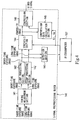
- Fig. 3 is a block diagram showing a schematic construction of the wide dynamic range camera according to the present embodiment.
- a microcomputer 137 corresponds to a control section of the present invention, but is not limited to this example.
- the wide D camera 102 may include an optical component 130, an image pickup device 131, a preprocessing section 132, a signal processing section 133, an output section 134, a TG 135, an EVR 136, the microcomputer 137 (hereinafter referred to as the microcomputer 137), an optical-component control circuit 138, and a recording medium 139.
- the optical component 130 is an optical filter which reduces unnecessary wavelengths, such as an ND filter. Light incident from a subject onto the optical component 130 and transmitted therethrough is picked up by the image pickup device 131, and is converted into an electrical signal.
- the optical component 130 has, for example, a lens iris and the like to be controlled by the microcomputer 137 via the optical-component control circuit 138.
- the microcomputer 137 will be descried later in detail.
- the image pickup device (image pickup device) 131 is capable of photoelectrically converting an optical image received from the subject and outputting an electrical image signal, by means of a plurality of pixels respectively made of photoelectric conversion devices disposed two-dimensionally on a light receiving surface.
- the image pickup device 131 is a solid-state image pickup device such as a CCD made of a multiplicity of kinds.
- the preprocessing section 132 if the image pickup device 131 is a CCD, receives the above-mentioned image signal outputted from the image pickup device 131, and then takes out a video signal while reducing noise (noise) by the processing of CDS (a correlated double sampling circuit; correlated double sampling).
- CDS a correlated double sampling circuit; correlated double sampling
- the preprocessing section 132 gives a gain to the video signal to amplify the video signal to a suitable signal level as occasion demands, and transmits the video signal to the signal processing section 133.
- the main noise of the CCD which constitutes the image pickup device 131 may include, for example, transfer noise, noise of an output amplifier, reset noise, noise caused by dark current, and light shot noise.
- the transfer noise is noise produced when charges are being transferred, but rarely becomes a problem since buried channel CCDs are generally used.
- the noise of the output amplifier is noise of a source follower, and if this noise is reduced, the noise of the CCD is ameliorated.
- the reset noise is noise produced when the FD (floating diffusion) of the CCD is reset, and CDS makes it possible to reduce this reset noise.
- the signal processing section 133 is made of two major blocks.
- One is a signal preprocessing block 140 which performs extraction of an inputted long-time exposure image and an inputted short-time exposure image each having a different exposure time, correction of the color balance between the long-time exposure image and the short-time exposure image, and synthesis and compression of the long-time exposure image and the short-time exposure image.
- the exposure times of the long-time exposure image and the short-time exposure image may be individually set according to subjects whose images are to be picked up.
- the signal preprocessing block 140 will be described later in detail.
- the other block following the signal preprocessing block is a signal postprocesing block (not shown) which performs color processing such as aperture (aperture) processing for performing y(gamma) correction and contour correction, and white balance for adjusting color temperature on the basis of "white" contained in the subject.
- color processing such as aperture (aperture) processing for performing y(gamma) correction and contour correction, and white balance for adjusting color temperature on the basis of "white" contained in the subject.
- the signal processing section 133 has at least a detection section 143 and is capable of detecting level information such as a luminance signal level, color information or the like of an image signal inputted at the present point in time.
- the signal processing section 133 is capable of calculating gains such as compression gains and adjusting white balance on the basis of the detected information.
- the detection section 143 will be described later in detail.
- the output section 134 receives the video signal from the signal processing section 133 after the processing of the signal processing section 133, and outputs a video image to a monitor such as a display device through a driver of the output section 134 in order to reproduce the video image.
- the TG (timing generator) 135 generates pulses necessary for the image pickup device 131 made of a CCD or the like. For example, pulses such as 4-phase pulses for vertical transfer, field shift pulses, and 2-phase pulses for horizontal transfer are generated.
- the image pickup device 131 may be driven (electronic shutter function) by the TG 135.
- image pickup processing is performed by the above-mentioned processing, but image pickup processing according to the present embodiment is not limited to this example.
- the EVR (electronic volume) 136 is a variable resistor whose resistance value may be adjusted by digital signals or the like, and controls the optical-component control circuit 138 and the like by varying the resistance value. Accordingly, iris adjustment of a lens which constitutes the optical component 130 may be performed by the EVR 136 and the like.
- the EVR 136 has storage means such as a memory, and may hold a varied resistance value when a power source is turned off.
- the optical-component control circuit 138 has control means (not shown) for performing control such as iris adjustment of the optical component 130 or switching from one optical filter to another such as an ND filter among a plurality of optical components 130.
- the microcomputer 137 controls the processing of each of the preprocessing section 132, the signal processing section 133, the TG 135, the EVR 136 and the optical-component control circuit 138 on the basis of, for example, a detection result from the above-mentioned detection section 143.
- the microcomputer 137 determines compression gains (compression gains) and the like for synthesizing and compressing a long-time exposure image (long) and a short-time exposure image (short) of the image pickup apparatus 102 which is the wide dynamic range camera.
- the microcomputer 137 will be described later in detail.
- the microcomputer 137 may control the image pickup apparatus 102 by mutually communicating, for example, control data for controlling the apparatus with an apparatus outside of the image pickup apparatus 102 via an "external I/F (external interface)".
- the "external I/F” is, for example, Ethernet (registered trademark) such as lOBase-T or 10Base-2, EIA-232, EIA-485 or the like.
- the storage medium 139 is capable of storing, for example, control data necessary for control of individual sections provided in the image pickup apparatus 102, adjustment data for adjustment of exposure of subjects, user setting data such as color correction and AE which may be variously set by individual users who use the image pickup apparatus 102.
- the storage medium 139 may use, for example, a ROM which may store data written thereto, and an EEPROM (Electrically Erasble and Programmable ROM) which may store or erase data by electrical erasure.
- a ROM which may store data written thereto
- EEPROM Electrical Erasble and Programmable ROM
- Fig. 4 is a block diagram showing a schematic construction of the signal preprocessing block according to the present embodiment.
- the microcomputer 137 corresponds to the control section of the present invention
- a compression gain calculation section 145 corresponds to a compression gain calculation section of the present invention
- this example is not restrictive.
- the compression gain calculation section 145 is provided in the signal preprocessing block 140, the present invention is not limited to this example, and may also be carried out even in various other cases such as the case where the compression gain calculation section 145 is provided in the microcomputer 137 as the control section, and the case where the compression gain calculation section 145 is provided in a section other than the signal preprocessing block 140.
- the signal preprocessing block 140 may include a timing adjustment section 141, clamp processings 142, a detection section 143, a synthesis section 144, the compression gain calculation section 145, and a compression section 146.
- the timing adjustment section 141 adjusts (synchronizes) the timings of image signals having different exposure times, which are respectively outputted from the preprocessing section 132 at different timings, to a synchronized timing. Synchronization processing in the timing adjustment section 141 will be described below.
- a long-time exposure image signal (long signal) containing a long-time exposure image (long) picked up by the image pickup device 131, and a short-time exposure image signal (short signal) containing a short-time exposure image (short) picked up by the same are transmitted from the preprocessing section 132 to the timing adjustment section 141 via one bus (path) shown in Fig. 4 in such a manner that the long signal and the short signal are alternately arranged by time sharing.
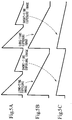
- Figs. 5A to 5C are explanatory views schematically showing the synchronization processing of the timing adjustment section 141 according to the present embodiment.
- the timing adjustment section 141 When the long-time exposure image signal and the short-time exposure image signal are alternately inputted to the timing adjustment section 141 in a time-shared manner, the timing adjustment section 141 performs synchronization on the long-time exposure image and the signal short-time exposure image signal.
- the above-mentioned synchronization extracts the long-time exposure image and the signal short-time exposure image signal contained in one signal, as shown in Fig. 5A , and adjusts (performs synchronization on) the temporal timing of the long-time exposure image contained in the long-time exposure image signal and the temporal timing of the short-time exposure image contained in the short-time exposure image signal, as shown in Fig. 5B (long-time exposure image signal) and 5C (short-time exposure image signal).
- the timing adjustment section 141 separately outputs the short-time exposure image and the long-time exposure image to the respective clamp processing sections 142.
- the synchronization is performed in the timing adjustment section 141, switching of pixels may be smoothly performed when the long-time exposure image and the short-time exposure image are to be synthesized in the synthesis section 144, whereby the synthesis section 144 may efficiently carry out synthesis processing.
- the clamp processing sections 142 determine a "0 level (black level)" reference from the luminance signal levels of the long-time exposure image and the short-time exposure image (clamp processing). After the determination of the 0 level, each of the clamp processing sections 142 outputs the corresponding one of the long-time exposure image and the short-time exposure image to both the synthesis section 144 and the detection section 143.
- the respective clamp processing sections 142 perform reproduction of direct current components, reduce low frequency noises, and determine where the 0 level is, by making use of the fact that the long-time exposure image signal and the short-time exposure image signal have periodicity.
- black levels are used as references, and direct current values represent information. Accordingly, in signal processing, the black levels are fixed, and the processing is performed on the basis of these levels.
- the detection section 143 detects what signal amount is inputted and what the luminance signal level is, as to each of the long-time exposure image signal and the short-time exposure image signal outputted from the clamp processing sections 142.
- the luminance signal level indicates the degree of brightness.
- the detection section 143 detects the signal amount or the distribution of the luminance signal level (a histogram of the luminance signal level) of each of the inputted long-time and short-time exposure images so that the microcomputer 137 in particular may determine a switch point for synthesis of the long-time exposure image and the short-time exposure image.
- the synthesis section 144 performs level adjustment on the exposure levels of the inputted long-time exposure image and short-time exposure image, and synthesizes both exposure images into one image by performing switch processing in units of pixels.
- the generated composite image is outputted to the compression section 146 and the compression gain calculation section 145 as a composite image signal.
- the synthesis processing of the synthesis section 144 to synthesize the long-time exposure image and the short-time exposure image will be described later in detail.
- the microcomputer 137 may receive the signal amounts or the histograms of the luminance signal levels detected from the respective long-time and short-time exposure image signals. In addition, an average luminance signal level and the like of a high luminance region or a low-middle luminance region may be found from the signal amount of each of the luminance signal levels.
- the microcomputer 137 on the basis of information such as the detection result acquired from the detection section 143, performs processing such as adjustment of the exposures of the short-time exposure image and the long-time exposure image, correction of the proportion of a high luminance dynamic range and a low-middle luminance dynamic range in the dynamic range of an output image to be outputted as a video signal, determination of the switch point for synthesis of the short-time exposure image and the short-time exposure image, or determination of the compression gains (compression gains) of the generated composite image.
- the above-mentioned switch point or compression gains and the like are transmitted to each of the processing sections of the signal preprocessing block 140 by the microcomputer 137.
- the respective compression gains are constructed for different luminance regions.
- the compression gains in the present embodiment include a high luminance compression gain (Gs) and a low-middle luminance compression gain (Gl), but this example is not restrictive.
- the compression gains may be made of a high luminance compression gain, a low-middle luminance compression gain and a low luminance compression gain.
- the operation processing of the microcomputer 137 such as determination of the switch point, correction of the proportion of the dynamic ranges and determination of the compression gains will be described later in detail.
- the compression gain calculation section (Compression Gain Calculator) 145 calculates final compression gains for the respective luminance signal levels to be compressed, on the basis of the above-mentioned compression gains (the high luminance compression gain (Gs) and the low-middle luminance compression gain (Gl)) transmitted from the microcomputer 137, and transmits the final compression gains to the compression section 146.
- the final compression gains in the present embodiment include a final high luminance compression gain and a final low-middle luminance compression gain, but this example is not restrictive.
- the compression section 146 compresses the dynamic range of the composite image synthesized by the synthesis section 144 to the dynamic range of an output image to be outputted as a video signal, on the basis of the inputted final compression gains.
- the compressed output image is transmitted to the next signal postprocessing block (not shown).
- the output image outputted from the compression section 146 is inputted to the signal postprocessing block, in which color processing such as gamma correction, aperture or white balance is executed.
- the image pickup apparatus 102 since the gamma characteristic of, for example, a CRT (Cathode Ray Tube, a picture tube) is determined, the image pickup apparatus 102 must perform correction in advance so that a reproduced picture may obtain correct grayscale characteristics. Accordingly, the correction needs to be performed by gamma correction. In general, diode characteristics are used.
- Fig. 6 is a flowchart schematically showing the image output processing of the image pickup apparatus according to the present embodiment.
- the image pickup apparatus 102 which is a wide dynamic camera performs image pickup processing (S160) of a subject by means of the image pickup device 131.
- image pickup processing is image pickup processing based on a double exposure method
- the present invention is not limited to this example, and may also be carried out in the case of, for example, a 2-CCD type which uses two image pickup devices 131 such as CCDs and has a standard-speed shutter and a high-speed shutter.
- the double exposure method is a method of picking up a long-time exposure image of a subject which needs a relatively long exposure time and whose correct exposure is in a low-middle luminance region and a short-time exposure image of a subject whose correct exposure is in a high luminance region, and synthesizing both images to expand an apparent dynamic range.
- luminance region means a region formed by an aggregation of pixels or signals constructed in an image having approximately the same luminance level.
- a high luminance region denotes a region formed by pixels or signals of high luminance levels, among pixels or signals constructed in an image.
- the long-time exposure image (long) and the short-time exposure image (short) which have been outputted from the image pickup device 131 and subjected to, for example, CDS processing by the preprocessing section 132 are transmitted to the timing adjustment section 141 of the signal preprocessing block 140 of the signal processing section 133 shown in Fig. 4 .
- both image signals are alternately inputted to the timing adjustment section 141 via one bus at different timings in such a manner that the long-time exposure image (long) and the short-time exposure image (short) are time-shared, so that both image signals need to be synchronized as described above.
- both exposure images are separately outputted from the timing adjustment section 141 and inputted to the clamp processing sections 142.
- the long-time exposure image and the short-time exposure image are transmitted to each of the detection section 143 and the synthesis section 144.
- the synthesis section 144 When the long-time exposure image and the short-time exposure image are transmitted to the synthesis section 144, the synthesis section 144 performs detection processing (S162) on the long-time exposure image and the short-time exposure image.
- the synthesis section 144 detects through the detection processing (S162) of the long-time exposure image and the short-time exposure image, for example, signal amounts at the respective signal levels of the long-time exposure image, signal amounts at the respective signal levels of the short-time exposure image, a distribution (histogram) of the signal amounts at the respective signal levels of the long-time exposure image, or a distribution of the signal amounts at the respective signal levels of the short-time exposure image.
- the microcomputer 137 determines La (switch luminance signal level) indicative of the highest luminance signal level in the low-middle luminance region in the long-time exposure image, and Lb indicative of the highest luminance signal level in the high luminance region in the short-time exposure image. La and Lb will be described later in detail.
- the synthesis processing (S164) is performed on the long-time exposure image and the short-time exposure image in the synthesis section 144, whereby a composite image is generated.
- the synthesis section 144 performs the synthesis processing (S164) on the basis of information transmitted from the microcomputer 137, for example, La. The synthesis processing will be described below in detail.
- the synthesis processing according to the present embodiment performs switching on the basis of the switch point (Switch point) so as to adopt pixels corresponding to the luminance signal levels of the long-time exposure image as to luminance signal levels lower than the switch point and, when the switch point is exceeded, adopt pixels corresponding to the luminance signal levels of the short-time exposure image.
- switch point switch point
- Fig. 7 is an explanatory view schematically showing the input/output characteristics of images during the synthesis processing according to the present embodiment.
- the input/output characteristic of the short-time exposure image (short) is a short-time input/output characteristic 170
- the input/output characteristic of the long-time exposure image (long) is a long-time input/output characteristic 171
- the input/output characteristic of the output image outputted from the signal processing section 133 as the video signal is an output image input/output characteristic 172.
- the horizontal axis shown in Fig. 7 represents the luminance signal levels of image signals inputted to the synthesis section 144
- the vertical axis represents the luminance signal levels of image signals outputted from the synthesis section 144.
- the exposure ratio of the long-time exposure image to the short-time exposure image is multiplied by the short-time exposure image, whereby the levels of both images are adjusted. For example, if the exposure ratio of the long-time exposure image to the short-time exposure image is 10:1, the exposure of the short-time exposure image is one-tenth of the long-time exposure image. However, the amount of existing light is ten times the luminance signal levels of the short-time exposure image. Accordingly, the levels are adjusted by multiplying the short-time exposure image by 10.
- the inclination of the short-time input/output characteristic 170 moves in the direction of the arrow shown in Fig. 7 , and the level of the short-time input/output characteristic 170 coincides with that of the long-time input/output characteristic 171. Furthermore, on the basis of an appropriate switch point (switch point), the short-time input/output characteristic 170 is inclined by the amount of predetermined inclination, whereby the output image input/output characteristic 172 is obtained.
- the predetermined inclination is stored in, for example, the storage medium 139, and further, the microcomputer 137 performs the processing of inclining the short-time input/output characteristic 171 level-adjusted by the above-mentioned multiplication, by the amount of the predetermined inclination.
- the reason for the short-time input/output characteristic 171 is inclined by the above-mentioned amount of inclination is that the dynamic range is very wide and noise such as image distortion needs to be avoided.
- pixels to be adopted for a composite image are switched from the long-time exposure image to the short-time exposure image on the basis of the switch point (switch point) shown in Fig. 7 , whereby one composite image is synthesized. Accordingly, a composite image is generated which has the characteristics of the long-time exposure image in which a dark section corresponding to the low-middle luminance signal levels is reproduced with good grayscale, and the characteristics of the short-time exposure image in which a bright section corresponding to the high luminance signal levels is reproduced with good grayscale, whereby the bright section and the dark section are reproduced with good grayscale.
- the pixels for the composite image are not equally adopted from the luminance signal levels of both the long-time exposure image and the short-time exposure image, and if there is not a signal amount corresponding to a luminance signal level, the exclusion processing of excluding the luminance signal level from the target to be synthesized is performed.
- the luminance signal level is not assigned to (is excluded from) the dynamic range of the composite image. Accordingly, it is possible to make effective use of the dynamic range to be assigned to the composite image.
- Fig. 8 is a cumulative histogram schematically showing a distribution of the luminance signal levels of the long-time exposure image according to the present embodiment
- Fig. 9 is a cumulative histogram schematically showing a distribution of the luminance signal levels of the short-time exposure image according to the present embodiment.
- the signal amount is accumulated.
- the luminance signal level exceeds La, the signal amount is not accumulated in the range of luminance signal levels shown as a range 180. Accordingly, in the range 180, a signal or a pixel is absent.
- the horizontal axis represents the luminance signal levels of image signals inputted to the synthesis section 144, while the vertical axis represents a cumulative signal amount.
- the luminance signal level corresponding to the range 180 is excluded from the target for the synthesis processing (S164). Accordingly, the excluded luminance signal level is not assigned to the dynamic range of the composite image, whereby it is possible to make effective use of the dynamic range.
- the luminance signal levels overlap the luminance signal levels of the short-time exposure image shown in Fig. 9 which will be mentioned later. Since the luminance signal levels of the high luminance region in the long-time exposure image in particular overlap the luminance signal levels of the short-time exposure image, the luminance signal levels are excluded from the target for the synthesis processing (S164).
- the present invention is not limited to this example, and may also be carried out in the case where, for example, a luminance signal level is set in advance and excluded.
- the pixels corresponding to the luminance signal levels in the long-time exposure image for the synthesis processing (S164) from which the range 180 and the range 182 are excluded become a target to be adopted for the composite image.
- the range of luminance signal levels to be adopted for the synthesis processing (S164) is a range lower than La.
- La in the present embodiment is determined by the microcomputer 137, the present invention is not limited to this example, and may also be carried out in the case of, for example, the detection section 143.
- the luminance regions according to the present embodiment are regions each having a predetermined luminance signal level range in an image, and the region in which luminances relatively correspond to low-middle luminances is made the low-middle luminance region, while the region in which luminances relatively correspond to high luminances is made the high luminance region.
- the present invention is not limited to this example, and may also be carried out in the case where, for example, the low-middle luminance region is further divided into a low luminance region and a middle luminance region.
- the highest luminance signal level of the high luminance region in the short-time exposure image is set to Lb, and pixels corresponding to lower luminance signal levels than Lb are made a target to be applied to the composite image.
- the luminance signal level is excluded from the target for the synthesis processing (S164). Accordingly, the excluded luminance signal level is not assigned to the dynamic range of the composite image, whereby it is possible to make effective use of the dynamic range with high use efficiency by assigning a section in which grayscales are absent to other luminance signal levels.
- switch point is La (switch luminance signal level)
- present invention is not limited to this example and may also be carried out in the case where a luminance signal level which is set in advance is used as a switch point.
- the dynamic range of the composite image synthesized in the synthesis processing (S164) is far wider than that of an image of, for example, a generally used type of video camera.
- none of the processing sections (devices) provided in the image pickup apparatus 102 which is the wide dynamic range camera is able to process the composite image signal, so that the dynamic range of the composite image needs to be compressed to a processable dynamic range (the dynamic range of the output image).
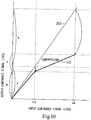
- Fig. 10 is an explanatory view schematically showing the input/output characteristic of the output image according to the present embodiment.
- the horizontal axis represents the luminance signal level of an image signal inputted to the compression section 146
- the vertical axis represents the luminance signal level of an image signal outputted from the compression section 146.
- the input/output characteristic of the composite image is a composite input/output characteristic 202
- the input/output characteristic of the output image in which the dynamic range of the composite image is compressed is the output image input/output characteristic 172.
- the output image is outputted from the signal preprocessing block 140 as a video signal, and is transmitted to the next signal postprocessing block (not shown).
- the dynamic range (dynamic range) according to the present embodiment may include the high luminance dynamic range which is the dynamic range of the high luminance region and the low-middle luminance dynamic range which is the dynamic range of the low-middle luminance region.
- the dynamic range is the range of brightness of a subject which may be handled by an image pickup device such as an image pickup device, i.e., the range of reproducible grayscales.
- the brightness or grayscale of an image dramatically varies according to what proportion of the grayscale of a subject should be assigned to which of the high luminance dynamic range and the low-middle luminance dynamic range in the above-mentioned dynamic range.
- the proportion of n in the reproduction ratio of m:n is increased to increase the proportion of the high luminance dynamic range, whereby the detail of the grayscale of the high luminance region is reproduced.
- the compression gains for compressing the dynamic range of the composite image are found by the microcomputer 137.
- the compression gains found by the microcomputer 137 are the low-middle luminance compression gain (Gl) found on the basis of La in the low-middle luminance region and the high luminance compression gain (Gs) found on the basis of Lb in the high luminance region.
- La or Lb is found by the microcomputer 137 on the basis of the detection result by the detection section 143, such as the signal amounts or the histogram of the luminance signal levels.
- the high luminance dynamic range and the low-middle luminance dynamic range of the composite image which are found by the equations (1) and (2) are respectively compressed by the compression section 146 in the directions indicated by the arrows shown in Fig. 10 , and the dynamic range of the composite image is assigned to the dynamic range of the output image.
- the assignment proportion of the high luminance dynamic range to the low-middle luminance dynamic range in the dynamic range of the composite image is assigned to the assignment proportion of the high luminance dynamic range to the low-middle luminance dynamic range in the dynamic range of the output image.
- the low-middle luminance compression gain (Gl) and the high luminance compression gain (Gs) which are respectively found by the equations (1) and (2) are compression gains at the input luminance signal levels La and Lb, respectively. Accordingly, to be exact, the compression gains at the individual luminance signal levels between La and Lb differ from Gl or Gs.
- the final compression gains are found by the compression gain calculation section 145.
- the compression gain calculation section 145 finds, on the basis of Gl and Gs transmitted from the microcomputer 137, a final low-middle luminance compression gain at each luminance signal level in the low-middle luminance region and a final high luminance compression gain at each luminance signal level in the high luminance region. Then, the compression gain calculation section 145 transmits the final high luminance compression gain and the final low-middle luminance compression gain to the compression section 146.
- Fig. 11 is an explanatory view schematically showing the input/output characteristic of the output image according to the present embodiment.
- the input/output characteristic of the output image shown in Fig. 11 is the output image input/output characteristic 172
- the input/output characteristic of a corrected output image is a corrected output image input/output characteristic 173
- the input/output characteristic of the composite image is the composite input/output characteristic 202.
- the proportion (reproduction ratio) of the low-middle luminance dynamic range to the high luminance dynamic range in the dynamic range of the output image is m:n, where n ⁇ 1 - m.
- the horizontal axis represents the luminance signal level of an image signal inputted to the compression section 146
- the vertical axis represents the luminance signal level of an image signal outputted from the compression section 146.
- the microcomputer 137 determines whether the proportion of a high luminance dynamic range to a low-middle luminance dynamic range in the dynamic range of an output image outputted previously is appropriate for a composite image to be newly inputted, and if the proportion is inappropriate, the microcomputer 137 performs correction by changing the proportion of the high luminance dynamic range to the low-middle luminance dynamic range to an appropriate proportion. Accordingly, it is possible to achieve efficient and appropriate assignment of the dynamic range.
- the assignment proportion of the high luminance dynamic range to the low-middle luminance dynamic range in the dynamic range of the output image is dynamically varied for each input composite image.
- the dynamic change of the proportion according to the present embodiment is executed each time a composite image is inputted, but the present invention is not limited to this example and may also be carried out in the case where the assignment proportion of the dynamic ranges is changed each time, for example, five composite images are inputted.
- the proportion of the high luminance dynamic range to the low-middle luminance dynamic range i.e., m:n, is corrected according to the signal amount of the high luminance region which occupies the composite image.
- the correction of the proportion of the high luminance dynamic range to the low-middle luminance dynamic range according to the present embodiment is performed on the basis of the proportion of the high luminance region found from the signal amount of the high luminance region (the area of the high luminance region) or the average luminance signal level of the high luminance region.
- the area of the high luminance region and the case of the average luminance signal level of the high luminance region will be separately described below.
- the correction of the dynamic range according to the present embodiment will be described with illustrative reference to the case where the correction is performed according to the high luminance region occupying the composite image, but the present invention is not limited to this example and may also be carried out in the case where the dynamic range is corrected on the basis of an area or an average luminance signal level found from the signal amount of the low luminance region or low-middle luminance region.
- f(x) is a correction function based on the area of the high luminance region.
- the input/output characteristic of the correction function f(x) will be described below with reference to Fig. 12.
- Fig. 12 is an explanatory view schematically showing the correction function based on the area of the high luminance region.
- the input/output characteristic of the correction function is an area input/output characteristic 220.
- the horizontal axis represents the proportion of the area of the high luminance region in the composite image, while the vertical axis represents correction values of the correction function f(x).
- the correction value of the correction function f(x) takes any value from "1.0" to "0". Furthermore, m' and n' of the corrected proportion are found from the equations (3) and (4), whereby the assignment processing (S166) is performed. If the proportion of the area is not less than Ra, the entire high luminance dynamic range is assigned to the low-middle luminance dynamic range in the assignment processing (S166), while if the proportion of the area exceeds Rb, the assignment processing (S166) is not performed and the proportion of the high luminance dynamic range to the low-middle luminance dynamic range remains unchanged.
- the corrected output image input/output characteristic 173 moves on the La axis in the vertically upward direction.
- the proportion in which the high luminance dynamic range is assigned to the low-middle luminance dynamic range increases.
- the proportion of the area of the high luminance region approaches Rb m' of the corrected proportion decreases, and the corrected output image input/output characteristic shown in Fig. 11 moves on the La axis in the vertically downward direction, and approaches m.
- the proportion of the dynamic range to be assigned to the low-middle luminance dynamic range increases, whereby the grayscale reproducibility of the low-middle luminance region is improved.
- the proportion of the high luminance dynamic range to the low-middle luminance dynamic range is dynamically varied for each inputted output image according to the signal amount of the high luminance region thereof, whereby the dynamic range is corrected into a dynamic range appropriate for the output image.
- the present invention is not limited to this example and may also be carried out in the case where the correction function f(x) draws, for example, a quadratic curve.
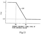
- the assignment processing (S166) based on the average luminance signal level of the high luminance region has approximately the same configuration as the assignment processing (S166) based on the area of the high luminance region, and as shown in Fig. 13 , the input/output characteristic based on the average luminance signal level of the high luminance region assumes an average luminance signal level 230, and the horizontal axis represents the average luminance signal level of the high luminance region.
- the corrected output image input/output characteristic 173 moves on the La axis in the vertically upward direction. This fact means that since the high luminance region decreases, the proportion in which the high luminance dynamic range is assigned to the low-middle luminance dynamic range increases.
- the proportion of the dynamic range to be assigned to the low-middle luminance dynamic range increases, whereby the grayscale reproducibility of the low-middle luminance region is improved.
- the proportion of the high luminance dynamic range to the low-middle luminance dynamic range is dynamically varied for each inputted output image according to the signal amount of the high luminance region thereof, whereby the dynamic range is corrected into a dynamic range appropriate for the output image.
- m' and n' of the corrected proportion are found by the microcomputer 137.
- Ra and Rb according to the present embodiment may be appropriately varied according to the characteristics of the image pickup apparatus 102, the kind of subject whose image is to be picked up, and the like.
- the present invention may also be carried out in the case where both the area of the high luminance region and the average luminance signal level thereof are used in combination.
- the correction function is expressed as F(x, x').
- the compression section 146 transmits the output image to the signal postprocessing block as a video signal, and one sequence of image output operations is completed.
- the dynamic range according to the present embodiment may include the low-middle luminance dynamic range which is the dynamic range of a region having luminances relatively corresponding to low-middle luminances, and the high luminance dynamic range which is the dynamic range of a region having luminances relatively corresponding to high luminances.
- the present invention is not limited to this example and may also be carried out in the case where, for example, the low-middle luminance dynamic range is further divided into a low luminance dynamic range and a middle luminance dynamic range.
- the present invention is not limited to this example, and may also be carried out in the case where the image pickup apparatus 102 picks up, for example, a color image or both a color image and a black-and-white image.
- dynamic ranges respectively assigned to a long-time exposure image and a short-time exposure image are dynamically varied according to the area of a high luminance region or the average luminance signal level of a high luminance section, whereby images may be reproduced with, for example, grayscale and exposure constantly maintained under optimum conditions. Furthermore, during synthesis, an unnecessary section such as the range of luminance signal levels in which signals are absent or the range of luminance signal levels overlapping the short-time exposure image is excluded from the long-time exposure image, whereby it is possible to make far more efficient use of the dynamic ranges.
Landscapes
- Engineering & Computer Science (AREA)
- Multimedia (AREA)
- Signal Processing (AREA)
- Studio Devices (AREA)
- Transforming Light Signals Into Electric Signals (AREA)
- Exposure Control For Cameras (AREA)
Claims (10)
- Bildaufnahmevorrichtung (102), umfassend:eine Bildaufnahmeeinrichtung (131) zum Aufnehmen eines Bildes eines Gegenstandes;einen Signalverarbeitungsabschnitt (133) zum Erzeugen eines zusammengesetzten Bildes mit einem relativ breiteren Dynamikbereich als mindestens entweder die Dynamikbereiche eines Langzeitbelichtungsbildes, das von der Bildaufnahmeeinrichtung mit einer relativ langen Belichtungszeit aufgenommen wurde, oder eines Kurzzeitbelichtungsbildes, das von der Bildaufnahmeeinrichtung mit einer relativ kurzen Belichtungszeit aufgenommen wurde, wobei der Signalverarbeitungsabschnitt umfasst:einen Syntheseabschnitt (144) zum Erzeugen des zusammengesetzten Bildes aus dem Langzeitbelichtungsbild und dem Kurzzeitbelichtungsbild basierend auf einem aus den Bildsignalen bestimmten Luminanz-Wechsel-Signalpegel,wobei der Syntheseabschnitt betreibbar ist, um aus dem Kurzzeitbelichtungsbild die Pixel zu erfassen, die mindestens einem Luminanzsignalpegel entsprechen, der höher als der Luminanz-Wechsel-Signalpegel ist, unter den in dem zusammengesetzten Bild aufgebauten Pixeln; undwobei der Syntheseabschnitt aus dem Langzeitbelichtungsbild die Pixel erfasst, die mindestens einem Luminanzsignalpegel entsprechen, der niedriger als der Luminanz-Wechsel-Signalpegel ist, unter den in dem zusammengesetzten Bild aufgebauten Pixeln, undeinen Steuerabschnitt (137) zum dynamischen Variieren des Zuordnungsanteils eines Dynamikbereichs mit hoher Luminanz zu einem Dynamikbereich mit niedriger mittlerer Luminanz in einem Dynamikbereich eines Ausgabebildes, das als Videosignal auszugeben ist, wenn das zusammengesetzte Bild erzeugt wird, dadurch gekennzeichnet, dasseine Korrekturfunktion, die von der Fläche der Region mit hoher Luminanz, die das zusammengesetzte Bild belegt, abhängig ist, von dem Steuerabschnitt verwendet wird, um Variationen der relativen Anteile der Dynamikbereiche zu bestimmen, um die Graustufen-Reproduzierbarkeit der Region mit niedriger mittlerer Luminanz zu verbessern, undes ferner einen Kompressionsabschnitt umfasst zum Komprimieren des Dynamikbereichs der Pixel, die mindestens einem höheren Luminanzsignalpegel entsprechen, innerhalb des Anteils des Dynamikbereichs des Ausgangsbildes, das einem Dynamikbereich mit hoher Luminanz zugeordnet ist, und Komprimieren der Pixel, die mindestens einem niedrigeren Luminanzsignalpegel entsprechen, innerhalb des Anteils des Dynamikbereichs des Ausgabebildes, das einem Dynamikbereich mit niedriger Luminanz zugeordnet ist, in dem erzeugten zusammengesetzten Bild.
- Bildaufnahmevorrichtung nach Anspruch 1, dadurch gekennzeichnet, dass der Steuerabschnitt den Zuordnungsanteil des Dynamikbereichs mit hoher Luminanz zu dem Dynamikbereich mit niedriger mittlerer Luminanz entsprechend mindestens einer Luminanzregion, die das zusammengesetzte Bild belegt, dynamisch variiert.
- Bildaufnahmevorrichtung nach Anspruch 1, dadurch gekennzeichnet, dass der Steuerabschnitt den Zuordnungsanteil des Dynamikbereichs mit hoher Luminanz zu dem Dynamikbereich mit niedriger mittlerer Luminanz jedes Mal korrigiert, wenn das zusammengesetzte Bild erzeugt wird.
- Bildaufnahmevorrichtung nach Anspruch 1, dadurch gekennzeichnet, dass der Steuerabschnitt den Zuordnungsanteil des Dynamikbereichs mit hoher Luminanz zu dem Dynamikbereich mit niedriger mittlerer Luminanz gemäß mindestens einem durchschnittlichen Luminanzsignalpegel der Region mit hoher Luminanz, die das zusammengesetzte Bild belegt, dynamisch variiert.
- Bildaufnahmevorrichtung nach Anspruch 1, dadurch gekennzeichnet, dass der Steuerabschnitt den Zuordnungsanteil des Dynamikbereichs mit hoher Luminanz zu dem Dynamikbereich mit niedriger mittlerer Luminanz entsprechend mindestens der Region mit hoher Luminanz, die das zusammengesetzte Bild belegt, dynamisch variiert.
- Bildaufnahmevorrichtung nach einem der vorhergehenden Ansprüche, wobei der Signalverarbeitungsabschnitt aufweist:einen Erkennungsabschnitt (143) zum Erkennen eines Bildsignals des Langzeitbelichtungsbildes, das von der Bildaufnahmeeinrichtung mit einer relativ langen Belichtungszeit aufgenommen wurde, und eines Bildsignals des Kurzzeitbelichtungsbildes, das von der Bildaufnahmeeinrichtung mit einer relativ kurzen Belichtungszeit aufgenommen wurde.
- Bildaufnahmevorrichtung nach Anspruch 6, wobei der Syntheseabschnitt einen Luminanzsignalpegel von einem Ziel für das zusammengesetzte Bild ausschließt, wenn mindestens das Bildsignal, das dem Luminanzsignalpegel entweder des Langzeitbelichtungsbildes oder des Kurzzeitbelichtungsbildes entspricht, fehlt.
- Bildaufnahmevorrichtung nach Anspruch 7, dadurch gekennzeichnet, dass der Syntheseabschnitt den Luminanzsignalpegel, der niedriger als der Luminanz-Wechsel-Signalpegel in dem Langzeitbelichtungsbild ist, als ein Ziel für das zusammengesetzte Bild auswählt.
- Bildaufnahmevorrichtung nach Anspruch 7, dadurch gekennzeichnet, dass der Syntheseabschnitt den Luminanzsignalpegel, der höher als der Luminanz-Wechsel-Signalpegel in dem Kurzzeitbelichtungsbild ist, als ein Ziel für das zusammengesetzte Bild auswählt.
- Bildaufnahmeverfahren, umfassend:Aufnehmen eines Bildes eines Gegenstandes mit einer Bildaufnahmeeinrichtung;Erzeugen eines zusammengesetzten Bildes mit einem relativ breiteren Dynamikbereich als mindestens entweder die Dynamikbereiche eines Langzeitbelichtungsbildes, das von der Bildaufnahmeeinrichtung mit einer relativ langen Belichtungszeit aufgenommen wurde, oder eines Kurzzeitbelichtungsbildes, das von der Bildaufnahmeeinrichtung mit einer relativ kurzen Belichtungszeit aufgenommen wurde, wobei der Erzeugungsschritt umfasst:Erzeugen des zusammengesetzten Bildes aus dem Langzeitbelichtungsbild und dem Kurzzeitbelichtungsbild basierend auf einem aus den Bildsignalen bestimmten Luminanz-Wechsel-Signalpegel,Erfassen der Pixel aus dem Kurzzeitbelichtungsbild, die mindestens einem Luminanzsignalpegel entsprechen, der höher als der Luminanz-Wechsel-Signalpegel ist, unter den in dem zusammengesetzten Bild aufgebauten Pixeln;Erfassen der Pixel aus dem Langzeitbelichtungsbild, die mindestens einem Luminanzsignalpegel entsprechen, der niedriger als der Luminanz-Wechsel-Signalpegel ist, unter den in dem zusammengesetzten Bild aufgebauten Pixeln, unddynamisches Variieren des Zuordnungsanteils eines Dynamikbereichs mit hoher Luminanz zu einem Dynamikbereich mit niedriger mittlerer Luminanz in einem Dynamikbereich eines Ausgangsbildes, das als ein Videosignal auszugeben ist, wenn das zusammengesetzte Bild erzeugt wird;dadurch gekennzeichnet, dass:eine Korrekturfunktion, die von der Fläche der Region mit hoher Luminanz, die das zusammengesetzte Bild belegt, abhängig ist, verwendet wird, um Variationen der relativen Anteile der Dynamikbereiche zu bestimmen, um die Graustufen-Reproduzierbarkeit der Region mit niedriger mittlerer Luminanz zu verbessern, unddas Verfahren umfasst:zum Komprimieren des Dynamikbereichs der Pixel, die mindestens einem höheren Luminanzsignalpegel entsprechen, innerhalb des Anteils des Dynamikbereichs des Ausgangsbildes, das einem Dynamikbereich mit hoher Luminanz zugeordnet ist, Komprimieren der Pixel, die mindestens einem niedrigeren Luminanzsignalpegel entsprechen, innerhalb des Anteils des Dynamikbereichs des Ausgangsbildes, das einem Dynamikbereich mit niedriger Luminanz zugeordnet ist, in dem erzeugten zusammengesetzten Bild.
Applications Claiming Priority (3)
| Application Number | Priority Date | Filing Date | Title |
|---|---|---|---|
| JP2002279256 | 2002-09-25 | ||
| JP2002279256A JP3801126B2 (ja) | 2002-09-25 | 2002-09-25 | 撮像装置,撮像装置の画像出力方法,およびコンピュータプログラム |
| PCT/JP2003/011923 WO2004030348A1 (ja) | 2002-09-25 | 2003-09-18 | 撮像装置、撮像装置の画像出力方法、およびコンピュータプログラム |
Publications (3)
| Publication Number | Publication Date |
|---|---|
| EP1545123A1 EP1545123A1 (de) | 2005-06-22 |
| EP1545123A4 EP1545123A4 (de) | 2008-11-19 |
| EP1545123B1 true EP1545123B1 (de) | 2018-04-25 |
Family
ID=32040452
Family Applications (1)
| Application Number | Title | Priority Date | Filing Date |
|---|---|---|---|
| EP03798416.8A Expired - Lifetime EP1545123B1 (de) | 2002-09-25 | 2003-09-18 | Abbildungseinrichtung, abbildungseinrichtungs-bildausgabeverfahren und computerprogramm |
Country Status (7)
| Country | Link |
|---|---|
| US (1) | US7609320B2 (de) |
| EP (1) | EP1545123B1 (de) |
| JP (1) | JP3801126B2 (de) |
| KR (1) | KR100968983B1 (de) |
| CN (1) | CN1685710B (de) |
| AU (1) | AU2003264496A1 (de) |
| WO (1) | WO2004030348A1 (de) |
Families Citing this family (100)
| Publication number | Priority date | Publication date | Assignee | Title |
|---|---|---|---|---|
| JP2006014117A (ja) * | 2004-06-29 | 2006-01-12 | Sony Corp | 物理情報取得方法および物理情報取得装置並びに物理量分布検知の半導体装置 |
| CN101015199B (zh) * | 2004-07-07 | 2011-10-19 | 日本电气株式会社 | 宽视野图像输入方法和装置 |
| JP4040613B2 (ja) * | 2004-08-31 | 2008-01-30 | キヤノン株式会社 | 撮像装置 |
| KR101029071B1 (ko) * | 2004-09-09 | 2011-04-18 | 삼성전자주식회사 | 감지 휘도 범위를 넓히기 위한 디지털 촬영 장치의 제어방법, 및 이 방법을 채용한 디지털 촬영 장치 |
| EP1669855A1 (de) * | 2004-12-02 | 2006-06-14 | Deutsche Thomson-Brandt Gmbh | Verfahren für das Erzeugen von Menüs in multiplen Sprachen |
| DE102004062382A1 (de) * | 2004-12-23 | 2006-07-13 | Siemens Ag | Bildcodierverfahren sowie Bildcodiervorrichtung |
| US7612804B1 (en) | 2005-02-15 | 2009-11-03 | Apple Inc. | Methods and apparatuses for image processing |
| US20070127909A1 (en) * | 2005-08-25 | 2007-06-07 | Craig Mowry | System and apparatus for increasing quality and efficiency of film capture and methods of use thereof |
| JP2007036714A (ja) * | 2005-07-27 | 2007-02-08 | Hitachi Ltd | 撮像装置 |
| WO2007038977A1 (en) * | 2005-09-19 | 2007-04-12 | Robert Bosch Gmbh | Image pickup apparatus |
| JP4649313B2 (ja) * | 2005-10-28 | 2011-03-09 | 株式会社東芝 | 固体撮像装置 |
| JP4567593B2 (ja) * | 2005-12-27 | 2010-10-20 | 三星デジタルイメージング株式会社 | 撮像装置および撮影方法 |
| JP2007274220A (ja) * | 2006-03-30 | 2007-10-18 | Samsung Techwin Co Ltd | 撮像装置および撮像方法 |
| JP4823743B2 (ja) * | 2006-04-03 | 2011-11-24 | 三星電子株式会社 | 撮像装置,及び撮像方法 |
| KR20070105028A (ko) * | 2006-04-25 | 2007-10-30 | 한국전기연구원 | 영상신호 처리장치 |
| JP2007300463A (ja) * | 2006-05-01 | 2007-11-15 | Opt Kk | カメラ装置および画像処理方法 |
| US20100231748A1 (en) * | 2006-05-09 | 2010-09-16 | Mitsuhiko Takeda | Imaging device |
| KR100843087B1 (ko) * | 2006-09-06 | 2008-07-02 | 삼성전자주식회사 | 영상 생성 장치 및 방법 |
| JP4483841B2 (ja) * | 2006-09-06 | 2010-06-16 | カシオ計算機株式会社 | 撮像装置 |
| JP4843461B2 (ja) * | 2006-11-13 | 2011-12-21 | 株式会社東芝 | 固体撮像装置 |
| US7825969B2 (en) * | 2006-12-15 | 2010-11-02 | Nokia Corporation | Image stabilization using multi-exposure pattern |
| US20090262074A1 (en) * | 2007-01-05 | 2009-10-22 | Invensense Inc. | Controlling and accessing content using motion processing on mobile devices |
| US8047075B2 (en) | 2007-06-21 | 2011-11-01 | Invensense, Inc. | Vertically integrated 3-axis MEMS accelerometer with electronics |
| US8141424B2 (en) | 2008-09-12 | 2012-03-27 | Invensense, Inc. | Low inertia frame for detecting coriolis acceleration |
| US8020441B2 (en) | 2008-02-05 | 2011-09-20 | Invensense, Inc. | Dual mode sensing for vibratory gyroscope |
| US7796872B2 (en) * | 2007-01-05 | 2010-09-14 | Invensense, Inc. | Method and apparatus for producing a sharp image from a handheld device containing a gyroscope |
| US8508039B1 (en) | 2008-05-08 | 2013-08-13 | Invensense, Inc. | Wafer scale chip scale packaging of vertically integrated MEMS sensors with electronics |
| US8462109B2 (en) * | 2007-01-05 | 2013-06-11 | Invensense, Inc. | Controlling and accessing content using motion processing on mobile devices |
| US8952832B2 (en) | 2008-01-18 | 2015-02-10 | Invensense, Inc. | Interfacing application programs and motion sensors of a device |
| US7934423B2 (en) | 2007-12-10 | 2011-05-03 | Invensense, Inc. | Vertically integrated 3-axis MEMS angular accelerometer with integrated electronics |
| US8250921B2 (en) | 2007-07-06 | 2012-08-28 | Invensense, Inc. | Integrated motion processing unit (MPU) with MEMS inertial sensing and embedded digital electronics |
| JP4905187B2 (ja) * | 2007-03-09 | 2012-03-28 | ソニー株式会社 | 画像処理装置、撮像装置、および画像処理方法、並びにコンピュータ・プログラム |
| JP4306750B2 (ja) | 2007-03-14 | 2009-08-05 | ソニー株式会社 | 撮像装置、撮像方法、露光制御方法、プログラム |
| JP4306752B2 (ja) * | 2007-03-19 | 2009-08-05 | ソニー株式会社 | 撮像装置、測光方法、輝度算出方法、プログラム |
| JP2008263262A (ja) * | 2007-04-10 | 2008-10-30 | Olympus Corp | 撮像装置 |
| JP4127411B1 (ja) * | 2007-04-13 | 2008-07-30 | キヤノン株式会社 | 画像処理装置及び方法 |
| JP4341691B2 (ja) | 2007-04-24 | 2009-10-07 | ソニー株式会社 | 撮像装置、撮像方法、露光制御方法、プログラム |
| KR100835894B1 (ko) * | 2007-06-18 | 2008-06-09 | (주)실리콘화일 | 다이내믹 레인지가 넓고, 색재현성과 해상능력이 우수한픽셀어레이 및 이미지센서 |
| JP4986747B2 (ja) * | 2007-07-09 | 2012-07-25 | キヤノン株式会社 | 撮像装置及び撮像方法 |
| ES2396318B1 (es) * | 2007-07-25 | 2013-12-16 | Tay HIOK NAM | Control de exposicion para un sistema de formacion de imagenes |
| US20090086074A1 (en) * | 2007-09-27 | 2009-04-02 | Omnivision Technologies, Inc. | Dual mode camera solution apparatus, system, and method |
| JP4424402B2 (ja) | 2007-09-28 | 2010-03-03 | ソニー株式会社 | 撮像装置、撮像制御方法、撮像制御プログラム |
| JP4893569B2 (ja) * | 2007-09-28 | 2012-03-07 | ソニー株式会社 | 撮像装置、撮像制御方法及び撮像制御プログラム |
| JP4438847B2 (ja) | 2007-09-28 | 2010-03-24 | ソニー株式会社 | 撮像装置、撮像制御方法及び撮像制御プログラム |
| JP4424403B2 (ja) | 2007-09-28 | 2010-03-03 | ソニー株式会社 | 撮像装置、撮像方法及び撮像プログラム |
| JP2009124638A (ja) * | 2007-11-19 | 2009-06-04 | Fujitsu Microelectronics Ltd | 画像信号処理回路 |
| JP2009152669A (ja) | 2007-12-18 | 2009-07-09 | Sony Corp | 撮像装置、撮像処理方法及び撮像制御プログラム |
| KR101415874B1 (ko) * | 2008-01-16 | 2014-07-09 | 삼성전기주식회사 | 동영상 획득 시스템 및 방법 |
| US8115858B2 (en) * | 2008-01-16 | 2012-02-14 | Samsung Electronics Co., Ltd. | System and method for acquiring moving images |
| JP4656168B2 (ja) | 2008-03-05 | 2011-03-23 | カシオ計算機株式会社 | 画像合成装置 |
| JP5286927B2 (ja) * | 2008-05-19 | 2013-09-11 | ソニー株式会社 | 画像合成装置、撮像装置、画像合成方法、およびプログラム |
| JP5083046B2 (ja) * | 2008-06-03 | 2012-11-28 | ソニー株式会社 | 撮像装置及び撮像方法 |
| KR101495895B1 (ko) | 2008-07-08 | 2015-02-25 | 삼성전자주식회사 | 넓은 동적 범위를 갖는 광전 변환장치 및 광전 변환방법 |
| JP4661922B2 (ja) * | 2008-09-03 | 2011-03-30 | ソニー株式会社 | 画像処理装置、撮像装置、固体撮像素子、画像処理方法およびプログラム |
| JP4561912B2 (ja) | 2008-09-12 | 2010-10-13 | ソニー株式会社 | 撮像装置、撮像方法及びプログラム |
| US8587681B2 (en) * | 2008-11-21 | 2013-11-19 | Omnivision Technologies, Inc. | Extended depth of field for image sensor |
| JP2010166558A (ja) * | 2008-12-19 | 2010-07-29 | Sanyo Electric Co Ltd | 撮像装置 |
| JP2010219624A (ja) * | 2009-03-13 | 2010-09-30 | Toshiba Corp | 画像信号処理装置及び画像信号処理方法 |
| DE102009003698A1 (de) * | 2009-03-30 | 2010-10-07 | Conti Temic Microelectronic Gmbh | Verfahren und Vorrichtung zur Fahrspurerkennung |
| JP5315125B2 (ja) * | 2009-05-20 | 2013-10-16 | 株式会社メガチップス | 画像処理装置、撮像装置、および合成画像の生成方法 |
| JP5005731B2 (ja) * | 2009-05-25 | 2012-08-22 | パナソニック株式会社 | カメラ装置および露光制御方法 |
| JP4973719B2 (ja) | 2009-11-11 | 2012-07-11 | カシオ計算機株式会社 | 撮像装置、撮像方法、及び撮像プログラム |
| US8390701B2 (en) * | 2010-04-29 | 2013-03-05 | Robert Bosch Gmbh | Method for processing an image signal for double or multiple exposure cameras |
| US9204113B1 (en) * | 2010-06-28 | 2015-12-01 | Ambarella, Inc. | Method and/or apparatus for implementing high dynamic range image processing in a video processing system |
| JP2012019392A (ja) * | 2010-07-08 | 2012-01-26 | Nikon Corp | 画像処理装置、電子カメラおよび画像処理プログラム |
| CN103125112B (zh) * | 2010-09-27 | 2015-07-08 | 富士胶片株式会社 | 成像设备以及成像方法 |
| US8610794B2 (en) * | 2010-10-12 | 2013-12-17 | Ability Enterprise Co., Ltd. | Method of producing an image with a light track |
| US8866929B2 (en) * | 2010-10-12 | 2014-10-21 | Ability Enterprise Co., Ltd. | Method of producing a still image |
| US8687914B2 (en) * | 2010-10-13 | 2014-04-01 | Ability Enterprise Co., Ltd. | Method of producing an image |
| CN102075688B (zh) * | 2010-12-28 | 2012-07-25 | 青岛海信网络科技股份有限公司 | 单帧双曝光图像宽动态处理方法 |
| US8947555B2 (en) | 2011-04-18 | 2015-02-03 | Qualcomm Incorporated | White balance optimization with high dynamic range images |
| JP5780885B2 (ja) * | 2011-08-26 | 2015-09-16 | キヤノン株式会社 | 撮像装置、その制御方法、および制御プログラム |
| JP5612001B2 (ja) | 2012-02-24 | 2014-10-22 | 株式会社東芝 | 画像処理装置及び固体撮像装置 |
| JP6046966B2 (ja) | 2012-04-19 | 2016-12-21 | キヤノン株式会社 | 画像処理装置及び画像処理方法、プログラム、並びに記憶媒体 |
| JP2014050042A (ja) * | 2012-09-03 | 2014-03-17 | Toshiba Corp | 画像処理装置及び固体撮像装置 |
| US9437171B2 (en) * | 2012-12-05 | 2016-09-06 | Texas Instruments Incorporated | Local tone mapping for high dynamic range images |
| CN103873780B (zh) * | 2012-12-17 | 2017-11-28 | 联想(北京)有限公司 | 一种采集视频的方法及电子设备 |
| US9019401B2 (en) * | 2013-02-26 | 2015-04-28 | GM Global Technology Operations LLC | System and method for creating an image with a wide dynamic range |
| KR101535006B1 (ko) * | 2014-01-27 | 2015-07-08 | (주) 넥스트칩 | 역광을 보정하기 위한 영상 처리 장치 및 방법 |
| CN103873781B (zh) * | 2014-03-27 | 2017-03-29 | 成都动力视讯科技股份有限公司 | 一种宽动态摄像机实现方法及装置 |
| US9544505B2 (en) | 2014-04-11 | 2017-01-10 | Hanwha Techwin Co., Ltd. | Image processing apparatus for synthesizing images based on a plurality of exposure time periods and image processing method thereof |
| US9307162B2 (en) * | 2014-05-21 | 2016-04-05 | Himax Imaging Limited | Local enhancement apparatus and method to generate high dynamic range images by blending brightness-preserved and brightness-adjusted blocks |
| JP6563646B2 (ja) * | 2014-12-10 | 2019-08-21 | ハンファテクウィン株式会社 | 画像処理装置および画像処理方法 |
| JP6463190B2 (ja) * | 2015-03-27 | 2019-01-30 | キヤノン株式会社 | 撮像装置及びその制御方法並びにプログラム |
| JP2017188760A (ja) * | 2016-04-05 | 2017-10-12 | ソニー株式会社 | 画像処理装置、画像処理方法、コンピュータプログラム及び電子機器 |
| JP6786273B2 (ja) | 2016-06-24 | 2020-11-18 | キヤノン株式会社 | 画像処理装置、画像処理方法、及びプログラム |
| JP6665754B2 (ja) * | 2016-10-26 | 2020-03-13 | 株式会社デンソー | 撮像装置 |
| JP6740866B2 (ja) * | 2016-11-07 | 2020-08-19 | 株式会社デンソー | 画像出力装置 |
| KR101880652B1 (ko) * | 2016-12-28 | 2018-07-20 | 한화시스템 주식회사 | 가시광 영상의 햇빛 반사 보정 장치 및 방법 |
| JP6852411B2 (ja) * | 2017-01-19 | 2021-03-31 | ソニー株式会社 | 映像信号処理装置、映像信号処理方法およびプログラム |
| CN109120859B (zh) * | 2017-06-26 | 2022-03-25 | 深圳光峰科技股份有限公司 | 一种影像数据处理装置及拍摄设备、显示系统 |
| CN110830727B (zh) * | 2018-08-07 | 2021-06-22 | 浙江宇视科技有限公司 | 曝光比自动调整方法及装置 |
| CN109167931B (zh) * | 2018-10-23 | 2021-04-13 | Oppo广东移动通信有限公司 | 图像处理方法、装置、存储介质及移动终端 |
| CN113170158B (zh) * | 2018-11-19 | 2023-07-11 | 杜比实验室特许公司 | 视频编码器和编码方法 |
| JP7204480B2 (ja) * | 2018-12-27 | 2023-01-16 | キヤノン株式会社 | 撮像装置、撮像システム、移動体及び撮像装置の制御方法 |
| KR102733063B1 (ko) * | 2019-03-19 | 2024-11-21 | 삼성전자주식회사 | 합성 이미지를 생성하는 전자 장치 및 방법 |
| GB2597174B (en) * | 2019-04-05 | 2023-06-28 | Project Giants Llc | Real-time video dynamic range analysis |
| CN110166706B (zh) * | 2019-06-13 | 2020-09-04 | Oppo广东移动通信有限公司 | 图像处理方法、装置、电子设备以及存储介质 |
| JP7217211B2 (ja) * | 2019-08-23 | 2023-02-02 | 日立Astemo株式会社 | 撮像装置及び撮像方法 |
| US12407939B2 (en) | 2022-09-15 | 2025-09-02 | Samsung Electronics Co., Ltd. | Method of operating image sensor and image device performing the same |
Citations (2)
| Publication number | Priority date | Publication date | Assignee | Title |
|---|---|---|---|---|
| JP2002084449A (ja) * | 2000-09-08 | 2002-03-22 | Sanyo Electric Co Ltd | 固体撮像素子を用いた撮像装置 |
| US7092019B1 (en) * | 1999-05-31 | 2006-08-15 | Sony Corporation | Image capturing apparatus and method therefor |
Family Cites Families (8)
| Publication number | Priority date | Publication date | Assignee | Title |
|---|---|---|---|---|
| JPS55130499A (en) | 1979-03-26 | 1980-10-09 | Mitsuhiro Kishi | Lifting gear |
| JP3528184B2 (ja) | 1991-10-31 | 2004-05-17 | ソニー株式会社 | 画像信号の輝度補正装置及び輝度補正方法 |
| JPH07212645A (ja) * | 1994-01-25 | 1995-08-11 | Hitachi Denshi Ltd | テレビジョンカメラ |
| JP3134784B2 (ja) * | 1996-08-05 | 2001-02-13 | 松下電器産業株式会社 | 画像合成回路 |
| JP2951910B2 (ja) * | 1997-03-18 | 1999-09-20 | 松下電器産業株式会社 | 撮像装置の階調補正装置及び階調補正方法 |
| NZ332626A (en) * | 1997-11-21 | 2000-04-28 | Matsushita Electric Industrial Co Ltd | Expansion of dynamic range for video camera |
| KR100363826B1 (ko) * | 1999-06-07 | 2002-12-06 | 히다치덴시 가부시키가이샤 | 넓은 다이내믹레인지의 영상신호를 생성하는텔레비젼신호처리장치와 그 신호처리장치를 가지는텔레비젼카메라 및 텔레비젼신호처리방법 |
| WO2001039490A1 (en) * | 1999-11-22 | 2001-05-31 | Matsushita Electric Industrial Co., Ltd. | Solid-state imaging device |
-
2002
- 2002-09-25 JP JP2002279256A patent/JP3801126B2/ja not_active Expired - Fee Related
-
2003
- 2003-09-18 WO PCT/JP2003/011923 patent/WO2004030348A1/ja not_active Ceased
- 2003-09-18 KR KR1020057005063A patent/KR100968983B1/ko not_active Expired - Fee Related
- 2003-09-18 US US10/528,968 patent/US7609320B2/en active Active
- 2003-09-18 CN CN038230143A patent/CN1685710B/zh not_active Expired - Fee Related
- 2003-09-18 EP EP03798416.8A patent/EP1545123B1/de not_active Expired - Lifetime
- 2003-09-18 AU AU2003264496A patent/AU2003264496A1/en not_active Abandoned
Patent Citations (2)
| Publication number | Priority date | Publication date | Assignee | Title |
|---|---|---|---|---|
| US7092019B1 (en) * | 1999-05-31 | 2006-08-15 | Sony Corporation | Image capturing apparatus and method therefor |
| JP2002084449A (ja) * | 2000-09-08 | 2002-03-22 | Sanyo Electric Co Ltd | 固体撮像素子を用いた撮像装置 |
Also Published As
| Publication number | Publication date |
|---|---|
| EP1545123A1 (de) | 2005-06-22 |
| EP1545123A4 (de) | 2008-11-19 |
| CN1685710A (zh) | 2005-10-19 |
| AU2003264496A1 (en) | 2004-04-19 |
| KR20050084580A (ko) | 2005-08-26 |
| WO2004030348A1 (ja) | 2004-04-08 |
| US7609320B2 (en) | 2009-10-27 |
| JP2004120205A (ja) | 2004-04-15 |
| KR100968983B1 (ko) | 2010-07-09 |
| JP3801126B2 (ja) | 2006-07-26 |
| US20060033823A1 (en) | 2006-02-16 |
| CN1685710B (zh) | 2010-09-29 |
Similar Documents
| Publication | Publication Date | Title |
|---|---|---|
| EP1545123B1 (de) | Abbildungseinrichtung, abbildungseinrichtungs-bildausgabeverfahren und computerprogramm | |
| US8711255B2 (en) | Visual processing apparatus and visual processing method | |
| US8077224B2 (en) | Imaging apparatus and imaging mode control method | |
| US5606630A (en) | Photographed image reproducing apparatus | |
| US7379094B2 (en) | Electronic still imaging apparatus and method having function for acquiring synthesis image having wide-dynamic range | |
| US6882754B2 (en) | Image signal processor with adaptive noise reduction and an image signal processing method therefor | |
| JP3074967B2 (ja) | 高ダイナミックレンジ撮像・合成方法及び高ダイナミックレンジ撮像装置 | |
| US20060044459A1 (en) | Image pickup apparatus, exposure control method, and computer program installed in the image pickup apparatus | |
| US7453496B2 (en) | Wide dynamic range digital image composition | |
| JP3999321B2 (ja) | 電子カメラ | |
| US8213063B2 (en) | Image sensing apparatus, image sensing system, and operating program product for image sensing system | |
| JP3551568B2 (ja) | 撮像装置 | |
| JP3297485B2 (ja) | 撮像装置 | |
| JP2003219205A (ja) | 撮像装置、表示装置、画像記録装置および画質補正方法 | |
| EP2515543B1 (de) | Vorrichtung und Verfahren zur Bilderfassung | |
| US7466352B2 (en) | Gamma correction device in image capturing apparatus | |
| EP0290264A2 (de) | Videokamera | |
| JP2002223386A (ja) | 撮影装置 | |
| JP2010271507A (ja) | 撮像装置、露出調整方法及びプログラム | |
| KR101408359B1 (ko) | 촬상장치 및 촬상방법 | |
| JPH1023324A (ja) | 撮像装置 | |
| JPH0955949A (ja) | 撮像装置 | |
| JP2000004445A (ja) | カメラ | |
| JP2008005083A (ja) | 撮像装置 | |
| JP2008306326A (ja) | 画像処理装置および画像処理方法 |
Legal Events
| Date | Code | Title | Description |
|---|---|---|---|
| PUAI | Public reference made under article 153(3) epc to a published international application that has entered the european phase |
Free format text: ORIGINAL CODE: 0009012 |
|
| 17P | Request for examination filed |
Effective date: 20050324 |
|
| AK | Designated contracting states |
Kind code of ref document: A1 Designated state(s): AT BE BG CH CY CZ DE DK EE ES FI FR GB GR HU IE IT LI LU MC NL PT RO SE SI SK TR |
|
| AX | Request for extension of the european patent |
Extension state: AL LT LV MK |
|
| DAX | Request for extension of the european patent (deleted) | ||
| RBV | Designated contracting states (corrected) |
Designated state(s): DE FR GB |
|
| A4 | Supplementary search report drawn up and despatched |
Effective date: 20081021 |
|
| 17Q | First examination report despatched |
Effective date: 20090128 |
|
| STAA | Information on the status of an ep patent application or granted ep patent |
Free format text: STATUS: EXAMINATION IS IN PROGRESS |
|
| GRAP | Despatch of communication of intention to grant a patent |
Free format text: ORIGINAL CODE: EPIDOSNIGR1 |
|
| STAA | Information on the status of an ep patent application or granted ep patent |
Free format text: STATUS: GRANT OF PATENT IS INTENDED |
|
| INTG | Intention to grant announced |
Effective date: 20170612 |
|
| GRAJ | Information related to disapproval of communication of intention to grant by the applicant or resumption of examination proceedings by the epo deleted |
Free format text: ORIGINAL CODE: EPIDOSDIGR1 |
|
| STAA | Information on the status of an ep patent application or granted ep patent |
Free format text: STATUS: EXAMINATION IS IN PROGRESS |
|
| INTC | Intention to grant announced (deleted) | ||
| GRAP | Despatch of communication of intention to grant a patent |
Free format text: ORIGINAL CODE: EPIDOSNIGR1 |
|
| STAA | Information on the status of an ep patent application or granted ep patent |
Free format text: STATUS: GRANT OF PATENT IS INTENDED |
|
| INTG | Intention to grant announced |
Effective date: 20171117 |
|
| GRAA | (expected) grant |
Free format text: ORIGINAL CODE: 0009210 |
|
| GRAS | Grant fee paid |
Free format text: ORIGINAL CODE: EPIDOSNIGR3 |
|
| STAA | Information on the status of an ep patent application or granted ep patent |
Free format text: STATUS: THE PATENT HAS BEEN GRANTED |
|
| AK | Designated contracting states |
Kind code of ref document: B1 Designated state(s): DE FR GB |
|
| REG | Reference to a national code |
Ref country code: GB Ref legal event code: FG4D |
|
| REG | Reference to a national code |
Ref country code: DE Ref legal event code: R096 Ref document number: 60351153 Country of ref document: DE |
|
| REG | Reference to a national code |
Ref country code: FR Ref legal event code: PLFP Year of fee payment: 16 |
|
| REG | Reference to a national code |
Ref country code: DE Ref legal event code: R097 Ref document number: 60351153 Country of ref document: DE |
|
| PLBE | No opposition filed within time limit |
Free format text: ORIGINAL CODE: 0009261 |
|
| STAA | Information on the status of an ep patent application or granted ep patent |
Free format text: STATUS: NO OPPOSITION FILED WITHIN TIME LIMIT |
|
| 26N | No opposition filed |
Effective date: 20190128 |
|
| PGFP | Annual fee paid to national office [announced via postgrant information from national office to epo] |
Ref country code: DE Payment date: 20200925 Year of fee payment: 18 Ref country code: GB Payment date: 20200922 Year of fee payment: 18 Ref country code: FR Payment date: 20200914 Year of fee payment: 18 |
|
| REG | Reference to a national code |
Ref country code: DE Ref legal event code: R119 Ref document number: 60351153 Country of ref document: DE |
|
| GBPC | Gb: european patent ceased through non-payment of renewal fee |
Effective date: 20210918 |
|
| PG25 | Lapsed in a contracting state [announced via postgrant information from national office to epo] |
Ref country code: GB Free format text: LAPSE BECAUSE OF NON-PAYMENT OF DUE FEES Effective date: 20210918 Ref country code: FR Free format text: LAPSE BECAUSE OF NON-PAYMENT OF DUE FEES Effective date: 20210930 Ref country code: DE Free format text: LAPSE BECAUSE OF NON-PAYMENT OF DUE FEES Effective date: 20220401 |