EP1542303A2 - Système de pile à combustible - Google Patents
Système de pile à combustible Download PDFInfo
- Publication number
- EP1542303A2 EP1542303A2 EP04029352A EP04029352A EP1542303A2 EP 1542303 A2 EP1542303 A2 EP 1542303A2 EP 04029352 A EP04029352 A EP 04029352A EP 04029352 A EP04029352 A EP 04029352A EP 1542303 A2 EP1542303 A2 EP 1542303A2
- Authority
- EP
- European Patent Office
- Prior art keywords
- cathode
- gas
- fuel cell
- oxidizing gas
- passage
- Prior art date
- Legal status (The legal status is an assumption and is not a legal conclusion. Google has not performed a legal analysis and makes no representation as to the accuracy of the status listed.)
- Granted
Links
- 239000000446 fuel Substances 0.000 title claims abstract description 384
- 238000010248 power generation Methods 0.000 claims abstract description 81
- 239000007789 gas Substances 0.000 claims description 550
- 230000001590 oxidative effect Effects 0.000 claims description 161
- 239000001257 hydrogen Substances 0.000 claims description 119
- 229910052739 hydrogen Inorganic materials 0.000 claims description 119
- 239000002737 fuel gas Substances 0.000 claims description 117
- UFHFLCQGNIYNRP-UHFFFAOYSA-N Hydrogen Chemical compound [H][H] UFHFLCQGNIYNRP-UHFFFAOYSA-N 0.000 claims description 116
- 238000002485 combustion reaction Methods 0.000 claims description 104
- 238000010926 purge Methods 0.000 claims description 36
- 239000000203 mixture Substances 0.000 claims description 32
- 238000011144 upstream manufacturing Methods 0.000 claims description 23
- 238000007865 diluting Methods 0.000 claims description 22
- 150000002431 hydrogen Chemical class 0.000 claims description 3
- 238000010276 construction Methods 0.000 description 25
- XLYOFNOQVPJJNP-UHFFFAOYSA-N water Substances O XLYOFNOQVPJJNP-UHFFFAOYSA-N 0.000 description 21
- 238000007254 oxidation reaction Methods 0.000 description 16
- 238000010586 diagram Methods 0.000 description 14
- 239000000463 material Substances 0.000 description 13
- IJGRMHOSHXDMSA-UHFFFAOYSA-N Atomic nitrogen Chemical compound N#N IJGRMHOSHXDMSA-UHFFFAOYSA-N 0.000 description 12
- 230000015556 catabolic process Effects 0.000 description 12
- 239000003054 catalyst Substances 0.000 description 12
- 238000006731 degradation reaction Methods 0.000 description 12
- 238000002156 mixing Methods 0.000 description 7
- VNWKTOKETHGBQD-UHFFFAOYSA-N methane Chemical compound C VNWKTOKETHGBQD-UHFFFAOYSA-N 0.000 description 6
- 229910052757 nitrogen Inorganic materials 0.000 description 6
- 239000005518 polymer electrolyte Substances 0.000 description 6
- 238000000034 method Methods 0.000 description 5
- 230000003247 decreasing effect Effects 0.000 description 4
- 230000002401 inhibitory effect Effects 0.000 description 4
- BASFCYQUMIYNBI-UHFFFAOYSA-N platinum Chemical compound [Pt] BASFCYQUMIYNBI-UHFFFAOYSA-N 0.000 description 4
- KJTLSVCANCCWHF-UHFFFAOYSA-N Ruthenium Chemical compound [Ru] KJTLSVCANCCWHF-UHFFFAOYSA-N 0.000 description 3
- 239000003345 natural gas Substances 0.000 description 3
- 229910052707 ruthenium Inorganic materials 0.000 description 3
- 230000002950 deficient Effects 0.000 description 2
- 238000001514 detection method Methods 0.000 description 2
- 229910052697 platinum Inorganic materials 0.000 description 2
- 239000008400 supply water Substances 0.000 description 2
- UGFAIRIUMAVXCW-UHFFFAOYSA-N Carbon monoxide Chemical compound [O+]#[C-] UGFAIRIUMAVXCW-UHFFFAOYSA-N 0.000 description 1
- PXHVJJICTQNCMI-UHFFFAOYSA-N Nickel Chemical compound [Ni] PXHVJJICTQNCMI-UHFFFAOYSA-N 0.000 description 1
- 238000010795 Steam Flooding Methods 0.000 description 1
- 239000000956 alloy Substances 0.000 description 1
- 229910045601 alloy Inorganic materials 0.000 description 1
- QVGXLLKOCUKJST-UHFFFAOYSA-N atomic oxygen Chemical compound [O] QVGXLLKOCUKJST-UHFFFAOYSA-N 0.000 description 1
- 229910002091 carbon monoxide Inorganic materials 0.000 description 1
- 230000003197 catalytic effect Effects 0.000 description 1
- 238000006243 chemical reaction Methods 0.000 description 1
- 238000004891 communication Methods 0.000 description 1
- 238000009833 condensation Methods 0.000 description 1
- 230000005494 condensation Effects 0.000 description 1
- 238000005260 corrosion Methods 0.000 description 1
- 230000007797 corrosion Effects 0.000 description 1
- 230000007423 decrease Effects 0.000 description 1
- 238000010790 dilution Methods 0.000 description 1
- 239000012895 dilution Substances 0.000 description 1
- 238000007599 discharging Methods 0.000 description 1
- 238000010438 heat treatment Methods 0.000 description 1
- 150000002500 ions Chemical class 0.000 description 1
- 239000012528 membrane Substances 0.000 description 1
- 238000012986 modification Methods 0.000 description 1
- 230000004048 modification Effects 0.000 description 1
- 239000001301 oxygen Substances 0.000 description 1
- 229910052760 oxygen Inorganic materials 0.000 description 1
Images


Classifications
-
- H—ELECTRICITY
- H01—ELECTRIC ELEMENTS
- H01M—PROCESSES OR MEANS, e.g. BATTERIES, FOR THE DIRECT CONVERSION OF CHEMICAL ENERGY INTO ELECTRICAL ENERGY
- H01M8/00—Fuel cells; Manufacture thereof
- H01M8/06—Combination of fuel cells with means for production of reactants or for treatment of residues
- H01M8/0606—Combination of fuel cells with means for production of reactants or for treatment of residues with means for production of gaseous reactants
- H01M8/0612—Combination of fuel cells with means for production of reactants or for treatment of residues with means for production of gaseous reactants from carbon-containing material
-
- H—ELECTRICITY
- H01—ELECTRIC ELEMENTS
- H01M—PROCESSES OR MEANS, e.g. BATTERIES, FOR THE DIRECT CONVERSION OF CHEMICAL ENERGY INTO ELECTRICAL ENERGY
- H01M8/00—Fuel cells; Manufacture thereof
- H01M8/04—Auxiliary arrangements, e.g. for control of pressure or for circulation of fluids
- H01M8/04223—Auxiliary arrangements, e.g. for control of pressure or for circulation of fluids during start-up or shut-down; Depolarisation or activation, e.g. purging; Means for short-circuiting defective fuel cells
- H01M8/04231—Purging of the reactants
-
- H—ELECTRICITY
- H01—ELECTRIC ELEMENTS
- H01M—PROCESSES OR MEANS, e.g. BATTERIES, FOR THE DIRECT CONVERSION OF CHEMICAL ENERGY INTO ELECTRICAL ENERGY
- H01M8/00—Fuel cells; Manufacture thereof
- H01M8/04—Auxiliary arrangements, e.g. for control of pressure or for circulation of fluids
- H01M8/04298—Processes for controlling fuel cells or fuel cell systems
- H01M8/04694—Processes for controlling fuel cells or fuel cell systems characterised by variables to be controlled
- H01M8/04955—Shut-off or shut-down of fuel cells
-
- H—ELECTRICITY
- H01—ELECTRIC ELEMENTS
- H01M—PROCESSES OR MEANS, e.g. BATTERIES, FOR THE DIRECT CONVERSION OF CHEMICAL ENERGY INTO ELECTRICAL ENERGY
- H01M8/00—Fuel cells; Manufacture thereof
- H01M8/06—Combination of fuel cells with means for production of reactants or for treatment of residues
- H01M8/0662—Treatment of gaseous reactants or gaseous residues, e.g. cleaning
-
- H—ELECTRICITY
- H01—ELECTRIC ELEMENTS
- H01M—PROCESSES OR MEANS, e.g. BATTERIES, FOR THE DIRECT CONVERSION OF CHEMICAL ENERGY INTO ELECTRICAL ENERGY
- H01M8/00—Fuel cells; Manufacture thereof
- H01M8/04—Auxiliary arrangements, e.g. for control of pressure or for circulation of fluids
- H01M8/04007—Auxiliary arrangements, e.g. for control of pressure or for circulation of fluids related to heat exchange
- H01M8/04014—Heat exchange using gaseous fluids; Heat exchange by combustion of reactants
- H01M8/04022—Heating by combustion
-
- H—ELECTRICITY
- H01—ELECTRIC ELEMENTS
- H01M—PROCESSES OR MEANS, e.g. BATTERIES, FOR THE DIRECT CONVERSION OF CHEMICAL ENERGY INTO ELECTRICAL ENERGY
- H01M8/00—Fuel cells; Manufacture thereof
- H01M8/04—Auxiliary arrangements, e.g. for control of pressure or for circulation of fluids
- H01M8/04082—Arrangements for control of reactant parameters, e.g. pressure or concentration
- H01M8/04089—Arrangements for control of reactant parameters, e.g. pressure or concentration of gaseous reactants
- H01M8/04104—Regulation of differential pressures
-
- H—ELECTRICITY
- H01—ELECTRIC ELEMENTS
- H01M—PROCESSES OR MEANS, e.g. BATTERIES, FOR THE DIRECT CONVERSION OF CHEMICAL ENERGY INTO ELECTRICAL ENERGY
- H01M8/00—Fuel cells; Manufacture thereof
- H01M8/04—Auxiliary arrangements, e.g. for control of pressure or for circulation of fluids
- H01M8/04298—Processes for controlling fuel cells or fuel cell systems
- H01M8/04694—Processes for controlling fuel cells or fuel cell systems characterised by variables to be controlled
- H01M8/04746—Pressure; Flow
-
- H—ELECTRICITY
- H01—ELECTRIC ELEMENTS
- H01M—PROCESSES OR MEANS, e.g. BATTERIES, FOR THE DIRECT CONVERSION OF CHEMICAL ENERGY INTO ELECTRICAL ENERGY
- H01M8/00—Fuel cells; Manufacture thereof
- H01M8/04—Auxiliary arrangements, e.g. for control of pressure or for circulation of fluids
- H01M8/04298—Processes for controlling fuel cells or fuel cell systems
- H01M8/04694—Processes for controlling fuel cells or fuel cell systems characterised by variables to be controlled
- H01M8/04791—Concentration; Density
-
- H—ELECTRICITY
- H01—ELECTRIC ELEMENTS
- H01M—PROCESSES OR MEANS, e.g. BATTERIES, FOR THE DIRECT CONVERSION OF CHEMICAL ENERGY INTO ELECTRICAL ENERGY
- H01M8/00—Fuel cells; Manufacture thereof
- H01M8/06—Combination of fuel cells with means for production of reactants or for treatment of residues
- H01M8/0606—Combination of fuel cells with means for production of reactants or for treatment of residues with means for production of gaseous reactants
-
- Y—GENERAL TAGGING OF NEW TECHNOLOGICAL DEVELOPMENTS; GENERAL TAGGING OF CROSS-SECTIONAL TECHNOLOGIES SPANNING OVER SEVERAL SECTIONS OF THE IPC; TECHNICAL SUBJECTS COVERED BY FORMER USPC CROSS-REFERENCE ART COLLECTIONS [XRACs] AND DIGESTS
- Y02—TECHNOLOGIES OR APPLICATIONS FOR MITIGATION OR ADAPTATION AGAINST CLIMATE CHANGE
- Y02E—REDUCTION OF GREENHOUSE GAS [GHG] EMISSIONS, RELATED TO ENERGY GENERATION, TRANSMISSION OR DISTRIBUTION
- Y02E60/00—Enabling technologies; Technologies with a potential or indirect contribution to GHG emissions mitigation
- Y02E60/30—Hydrogen technology
- Y02E60/50—Fuel cells
Definitions
- the present invention relates to a fuel cell system and, more particularly to treatment of a combustible gas filled in a cathode of a fuel cell in the fuel cell system after stop of power generation.
- a fuel cell system 39 comprises, as main components, a polymer electrolyte fuel cell (PEFC) 1 provided with an anode 1a and a cathode 1c, a fuel generator 2 configured to reform a feed gas for power generation such as a city gas or a natural gas by addition of water to generate a hydrogen-rich fuel gas, a water supply device 3 configured to supply water to the fuel generator 2, a feed gas supply device 36 configured to supply the feed gas to the fuel generator 2, a combustor 4 configured to combust a fuel gas unconsumed in the anode 1a of the fuel cell 1 and exhausted therefrom, a blower 5 which is an oxidizing gas supply device configured to supply an oxidizing gas (air) to the fuel cell 1 and to discharge the oxidizing gas outside the fuel cell 1, and a purge air supply device 6 configured to supply purge air to the fuel generator 2 to perform purging from the interior from the fuel generator 2 when the fuel cell system 39 stops power generation.
- PEFC polymer electrolyte fuel cell
- the fuel cell system 39 is configured to generate electric power by reacting the hydrogen-rich fuel gas supplied to the anode 1a and the air supplied to the cathode 1c as the oxidizing gas within the fuel cell 1. In a stop operation of the fuel cell system 39, finally, purging of fuel gas passages is conducted by using the purge air.
- the fuel cell system 39 is configured to carry out the power generation operation and the stop operation under the condition in which a controller 21 properly controls the blower 5, the feed gas supply device 36, the water supply device 3, the air supply device 6, etc.
- a cost can be reduced because of the absence of a nitrogen storage device, as compared to the conventional purging process in which, when the fuel cell system stops the power generation, nitrogen, instead of the feed gas, is flowed from a feed gas supply passage to the fuel generator and to the fuel cell to purge the gases (e.g., fuel gas) remaining within these components to the combustor, which treats the purged gases.
- nitrogen instead of the feed gas
- a fuel cell system which employs such air purging technique is disclosed in WO01/97.312 (see pamphlet).
- water is supplied from a water supply device to a fuel generator to generate steam, which is used to purge a fuel gas containing hydrogen remaining within fuel gas passages, and thereafter, the air is flowed from a purge air supply device to finally perform purging from the interior of the fuel gas passages.
- hydrogen of the fuel cell is driven out by the steam and then the air is supplied to the interior of the fuel cell. This makes it possible to inhibit corrosion of the passages which may be caused by water droplets resulting from steam condensation.
- An anode of a polymer electrolyte fuel cell is typically comprised of alloy catalyst containing platinum and ruthenium. If the anode is exposed to air as in the conventional fuel cell system, catalyst may be oxidized by oxygen and possibly degrade catalytic performance (i.e., oxidization and degradation of the anode may take place). Considering maintaining durability of the fuel cell system, it is undesirable to fill and keep the air in the anode when the fuel cell system stops power generation.
- the fuel gas e.g., hydrogen-rich fuel gas
- the feed gas city gas or natural gas
- the cathode of the fuel cell is filled with the fuel gas or the feed gas after the stop of the power generation, the combustible feed gas or fuel gas is discharged to atmosphere when the air is supplied from an air supply system to the cathode of the fuel cell at the start of a next operation of the fuel cell.
- the present invention has been developed under the circumstances, and an object of the present invention is to provide a fuel cell system capable of appropriately treating and discharging a combustible gas filled in a cathode of a fuel cell.
- a fuel cell system comprising: a fuel cell configured to generate electric power using an oxidizing gas supplied to a cathode of the fuel cell, wherein a combustible gas is filled and kept in the cathode after stop of power generation, and is thereafter diluted by an incombustible gas when the combustible gas is discharged to atmosphere.
- the combustible gas in a gas mixture containing the combustible gas and the incombustible gas is appropriately diluted to have a concentration lower than a combustion lower limit, and the gas mixture in this diluted state is discharged to atmosphere.
- the fuel cell system may further comprise an oxidizing gas supply device configured to supply the oxidizing gas; an oxidizing gas passage through which the oxidizing gas supplied from the oxidizing gas supply device is guided to the cathode, and the oxidizing gas unconsumed in the cathode is discharged to atmosphere; first and second oxidizing gas passage valves respectively provided at an upstream position and a downstream position of the cathode in a flow of the oxidizing gas and configured to open and close the oxidizing gas passage; a combustible gas supply device configured to supply the combustible gas to a portion of the oxidizing gas passage which is located between the first oxidizing gas passage valve and the cathode; a diluting device configured to dilute the combustible gas purged from the cathode to a portion of the oxidizing gas passage which is located downstream of the cathode by the incombustible gas and to discharge the diluted combustible gas to atmosphere; and a controller, wherein
- the diluting device may include a cathode bypass passage configured to connect a portion of the oxidizing gas passage which is located upstream of the first oxidizing gas passage valve to a portion of the oxidizing gas passage which is located downstream of the second oxidizing gas passage valve, and a cathode bypass valve configured to open and close the cathode bypass passage, and when the combustible gas filled and kept in the cathode is discharged, the first and second oxidizing gas passage valves are opened, and the cathode bypass valve is opened to allow the combustible gas exhausted to the portion of the oxidizing gas passage which is located downstream of the cathode to be mixed with and diluted by the oxidizing gas flowing through the cathode bypass passage, the diluted combustible gas being discharged to atmosphere.
- a cathode bypass passage configured to connect a portion of the oxidizing gas passage which is located upstream of the first oxidizing gas passage valve to a portion of the oxidizing gas passage which is located
- the flow rate of the oxidizing gas flowing through the cathode bypass passage can be controlled.
- the flow rate of the oxidizing gas flowing through the cathode bypass passage may be controlled by adjusting an aperture diameter of a cathode bypass valve which is the cathode bypass valve disposed in the cathode bypass passage.
- the diluting device may include a cathode bypass passage configured to connect a portion of the oxidizing gas passage which is located upstream of the cathode to a portion of the oxidizing gas passage which is located downstream of the second oxidizing gas passage valve, and a dividing device disposed at a connecting portion between the portion of the oxidizing gas passage which is located upstream of the cathode and the cathode bypass passage, the dividing device being configured to open and close the oxidizing gas passage and to vary a ratio of a flow rate of the oxidizing gas flowing through the cathode bypass passage to a flow rate of the oxidizing gas flowing through the oxidizing gas passage as the diluting device and the first oxidizing gas passage valve, wherein when the combustible gas filled and kept in the cathode is discharged, the second oxidizing gas passage valve may be opened and the combustible gas exhausted to the portion of the oxidizing gas passage which is located downstream of the cathode may be mixed with and diluted
- the diluting device may include a combustion air supply device configured to supply air to a flame burner of a combustor, a cathode combustion pipe configured to extend from a position of the oxidizing gas passage between the second oxidizing gas passage valve and the cathode and to be connected to the flame burner, and a combustion pipe valve configured to open and close the cathode combustion pipe, and wherein when the combustible gas filled and kept in the cathode is discharged, the second oxidizing gas passage valve is closed and the combustion pipe valve is opened, thereby allowing the combustible gas to be guided to the flame burner through the cathode combustion pipe and to be mixed with and diluted by the air supplied from the combustion air supply device, the diluted combustible gas being discharged to atmosphere.
- the existing combustion air supply device the combustible gas filled in the cathode is appropriately mixed with and diluted by the air and the diluted combustible gas is discharged to atmosphere.
- the combustible gas may be introduced to the flame burner during a stop period of combustion in the combustor so that a combustion state of the flame burner is not disturbed by the supply of the combustible gas.
- the diluting device may include an exhaust pipe through which an exhaust gas generated by combustion in the combustor is guided to atmosphere, a cathode exhaust pipe configured to extend from a position of the oxidizing gas passage between the second oxidizing gas passage valve and the cathode and to be connected to the exhaust pipe, and an exhaust pipe valve configured to open and close the cathode exhaust pipe, and wherein when the combustible gas filled and kept in the cathode is discharged, the second oxidizing gas passage valve is closed and the exhaust pipe valve is opened, thereby allowing the combustible gas to be guided to the exhaust pipe through the cathode exhaust pipe and to be mixed with and diluted by the exhaust gas, the diluted combustible gas being discharged to atmosphere.
- the diluting device may include an exhaust pipe through which an exhaust gas generated by combustion in the combustor is guided to atmosphere, the exhaust pipe being connected to a portion of the oxidizing gas passage which is located downstream of the second oxidizing gas passage valve, and wherein when the combustible gas filled and kept in the cathode is discharged, the second oxidizing gas passage valve is opened, thereby allowing the combustible gas to be guided to the exhaust pipe through the oxidizing gas passage and to be mixed with and diluted by the exhaust gas, the diluted combustible gas being discharged to atmosphere.
- the combustible gas filled in the cathode When the combustible gas filled in the cathode is introduced into the exhaust pipe, the combustible gas may be introduced into the exhaust pipe during a combustion period of the combustor. Thereby, the combustible gas can be introduced irrespective of the combustion in the flame burner, and consequently, a process can be simplified.
- the combustor may be configured to heat a fuel generator configured to generate a fuel gas from a feed gas.
- the fuel cell system may further comprises a fuel generator configured to generate a fuel gas from a feed gas, wherein the fuel gas may be supplied from the fuel generator to an anode of the fuel cell to generate electric power, and the combustible gas may be one of the feed gas and the fuel gas.
- a fuel generator configured to generate a fuel gas from a feed gas, wherein the fuel gas may be supplied from the fuel generator to an anode of the fuel cell to generate electric power, and the combustible gas may be one of the feed gas and the fuel gas.
- the fuel cell system may further comprise a hydrogen supply device configured to supply hydrogen, wherein the hydrogen may be supplied from the hydrogen supply device to an anode of the fuel cell to generate electric power, and the combustible gas may be hydrogen.
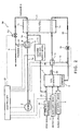
- Fig. 1 is a block diagram schematically showing a construction of a fuel cell system according to a first embodiment of the present invention.
- a fuel cell system 39 comprises, as main components, a feed gas supply device 36, a polymer electrolyte fuel cell (PEFC) 1, a fuel generator 2, a water supply device 3, a combustor 4, a purge air supply device 6, and a blower 5.
- the feed gas supply device 36 is configured to supply a feed gas for power generation such as a city gas or a natural gas to the fuel generator 2 through a material supply pipe 33.
- the polymer electrolyte fuel cell 1 is configured to generate electric power using a fuel gas and an oxidizing gas (air).
- the fuel generator 2 is configured to reform the feed gas by adding water to generate a hydrogen-rich fuel gas.
- the water supply device 3 is configured to supply water to the fuel generator 2.
- the combustor 4 is configured to combust a fuel gas unconsumed in an anode 1a of the fuel cell 1 and exhausted therefrom.
- the purge air supply device 6 is configured to supply purge air to the fuel generator 2 when the fuel cell system 39 stops power generation.
- the blower 5, which is an oxidizing gas supply device, is configured to supply the oxidizing gas to a cathode 1c of the fuel cell 1, and to exhaust remaining oxidizing gas from the cathode 1c.
- a gas pipe system of the fuel cell system 39 includes a cathode supply pipe 7, a cathode discharge pipe 8, a cathode bypass pipe 9, a cathode bypass valve 10, a cathode closing device 12, a material supply pipe 33, an anode supply pipe 34, a fuel gas return pipe 35, a return pipe valve 15, an anode bypass pipe 13, a cathode feed gas supply pipe 32, and a cathode feed gas supply device (combustible gas supply device) 11.
- the air is supplied from the blower 5 to the cathode 1c of the fuel cell 1 through the cathode supply pipe (oxidizing gas passage) 7.
- the cathode bypass pipe 9 which is a cathode bypass passage, is provided to connect the cathode supply pipe 7 to the cathode discharge pipe 8 and configured to guide the air supplied from the blower 5 to the cathode discharge pipe 8 without flowing the air through the fuel cell 1.
- the cathode bypass valve 10 is provided in the cathode bypass pipe 9 and configured to open and close the cathode bypass pipe 9.
- the cathode closing device 12 is comprised of a first exit-side valve (second oxidizing gas passage valve) 12a and a first inlet-side valve (first oxidizing gas passage valve) 12b configured to open and close an exit and an inlet of the cathode 1c of the fuel cell 1, respectively.
- the feed gas is supplied from the feed gas supply device 36 to the fuel generator 2 through the material supply pipe 33.
- the fuel gas from the fuel generator 2 is guided to the anode 1a of the fuel cell 1 through the anode supply pipe 34 and a passage switching device 14.
- the remaining fuel gas is exhausted from the anode 1a of the fuel cell 1 to the combustor 4 through the fuel gas return pipe 35.
- the return pipe valve 15 is provided in the fuel gas return pipe 35 and configured to open and close the fuel gas return pipe 35.
- the fuel gas from the fuel generator 2 is guided by the passage switching device 14 to flow to the anode bypass pipe 13, and guided to a portion of the fuel gas return pipe 35 which is located downstream of the return pipe valve 15 in a flow of the fuel gas.
- the cathode feed gas supply pipe 32 is configured to connect the material supply pipe 33 to the portion of the cathode supply pipe 7 which is located downstream of the first inlet-side valve 12b in a flow of the feed gas:
- the cathode feed gas supply device 1-1 is provided in the cathode feed gas supply pipe 32 and configured to introduce the feed gas into the cathode 1c.
- the cathode bypass pipe 9 is configured to connect a portion of the cathode supply pipe (oxidizing gas passage) 7 which is located upstream of the first inlet-side valve (first oxidizing gas passage valve) 12b in a flow of the oxidizing gas to a portion of the cathode discharge pipe (oxidizing gas passage) 8 which is located downstream of the first exit-side valve (second oxidizing gas passage valve) 12a.
- a combustible gas diluting device is formed by the cathode bypass passage 9 and the cathode bypass valve 10 configured to open and close the cathode bypass pipe 9.
- the cathode bypass valve 10, the first exit-side valve 12a and the first inlet-side valve 12b of the cathode closing device 12, and the return pipe valve 15 are each formed by an electromagnetic valve.
- the passage switching device 14 is formed by, for example, a three-way valve.
- the cathode feed gas supply device 11 is formed by, for example, an electromagnetic valve or a pump.
- the controller 21 is electrically connected to the blower 5, the feed gas supply device 36, the water supply device 3, the purge air supply device 6, the cathode feed gas supply device 11, and the valves 10, 12a, 12b, 14, and 15 and configured to control these components, thereby controlling the operation of gas supply system of the fuel cell system 39 to be described later.
- the control executed by the controller 21 is represented by a dashed line in Fig. 1.
- the controller 21 is electrically connected to sensors (a temperature sensor or a flow rate meter) and configured to receive detection signals from these sensors and to properly control operations including start-up, power generation, and stop of the fuel cell system 39.
- the feed gas supplied from the feed gas supply device 36 and the water supplied from the water supply device 3 are reformed within the fuel generator 2 to generate a hydrogen-rich fuel gas with the temperature of the fuel generator 2 kept at approximately 700°C.
- the fuel gas from the fuel generator 2 flows through the passage switching device 14 provided in the anode supply pipe 34 (which allows the anode supply pipe 34 and the anode 1a to communicate with each other) and into the anode 1a of the fuel cell 1.
- the air is supplied from the blower 5 to the cathode 1c of the fuel cell 1 through the cathode supply pipe 7 and the first inlet-side valve 12b in an open position.
- the fuel gas (hydrogen) and the air (oxidizing gas) are consumed to generate electric power.
- the fuel gas unconsumed in the power generation of the fuel cell 1 is guided to the combustor 4 through the fuel gas return pipe 35 and the return pipe valve 15 in an open position and then combusted within the combustor 4 to generate a heat source for keeping the temperature of the fuel generator 2.
- the air unconsumed in the power generation of the fuel cell 1 is discharged to atmosphere through the cathode discharge pipe 8 and the first exit-side valve 12a in an open position.
- the gas supply to the cathode 1c of the fuel cell 1 is controlled as described below.
- the operation of the blower 5 is stopped to stop the air supply to the cathode 1c.
- the cathode feed gas supply device 11 operates to allow the feed gas (combustible gas) to be guided to the portion of the cathode supply pipe 7 which is located downstream of the first inlet-side valve 12b through the cathode feed gas supply pipe 32 and to be supplied to the cathode 1c of the fuel cell 1 through this portion of the cathode supply pipe 7.
- the first inlet-side valve 12b is closed and the first exit-side valve 12a is opened.
- the feed gas supplied to the cathode 1c purges the air remaining in the cathode 1c so that the air is discharged to atmosphere from the cathode 1c through the cathode discharge pipe 8.
- the first exit-side valve 12a of the cathode closing device 12 is closed, and the supply of the feed gas to the cathode 1c of the fuel cell 1 is stopped by closing the cathode feed gas supply device 11 in a case where the cathode feed gas supply device 11 is formed by a valve. Since the amount of air remaining in the cathode 1c can be known in advance, the amount of the feed gas capable of purging almost all the air is determined based on the amount of remaining air.
- the pressure of the feed gas which exists in the material supply pipe 33 just after an exit of the feed gas supply device 36 has been increased by approximately 2kPa.
- the valve which is the cathode feed gas supply device 11 provided in the cathode feed gas supply pipe 32
- one end of the cathode feed gas supply pipe 32 connected to the portion of the material supply pipe 33 which is located just after the exit of the feed gas supply device 36 and the other end thereof connected to the portion of the cathode supply pipe 7 which is located downstream of the first inlet-side valve 12b
- the feed gas can be flowed from the portion of the cathode supply pipe 7 which is located downstream of the first inlet-side valve 12b into the cathode 1 by utilizing an internal pressure of the feed gas.
- a feed pump may be used as the cathode feed gas supply device 11 to send the feed gas under pressure to the cathode 1c.
- the passage switching device 14 forms the bypass passage (allowing the anode supply pipe 34 and the anode bypass pipe 13 to communicate with each other), and the valve 15 is closed. Thereby, the fuel gas (hydrogen-rich gas) remaining in the anode 1a of the fuel cell 1 is confined therein, and under this condition, the supply of the fuel gas from the fuel generator 2 to the anode 1a is stopped.
- the fuel gas hydrogen-rich gas
- the combustible gas feed gas
- the water supply device 3 is operated to supply the water to the fuel generator 2.
- the water supplied to the fuel generator 2 is evaporated into steam by the heat of the fuel generator 2, and the steam drives out the hydrogen-rich fuel gas remaining in the fuel generator 2 into the anode supply pipe 34.
- the fuel gas and the steam are returned to the combustor 4 by the passage switching device 14 through the anode bypass pipe 13 and the fuel gas return pipe 35 and combusted therein.
- the combustible gas contained in the fuel gas is diluted to lower its concentration, and in time, the combustor 4 stops combustion, while the steam continues to be generated by the remaining heat in the fuel generator 2.
- the supply of the water from the water supply device 3 is stopped. Thereafter, the air is supplied from the purge air supply device 6 to the fuel generator 2 to allow the steam in the fuel generator 2 to be purged from the fuel generator 2 to the anode supply pipe 34, and the passage switching device 14 causes the air to return to the combustor 4 through the anode bypass pipe 13 and the fuel gas return pipe 35. The air is discharged from the combustor 4 to atmosphere.
- the operation of the purge air supply device 6 is stopped to stop the supply of the air, and thereby the stop operation of the fuel cell system 39 is terminated.
- the temperature of 400°C which is herein used as the reference, is set considering a predetermined safety ratio to inhibit degradation of performance which is caused by oxidization and degradation of ruthenium catalyst exposed to air under a high-temperature condition, assuming that a catalyst mainly containing ruthenium is used in the fuel generator 2. For this reason, the set temperature shifts according to the safety ratio, and varies according to the type of catalyst (e.g., nickel catalyst).
- the supply of the gas to the cathode 1c of the fuel cell 1 is controlled as described below.
- the first inlet-side and exit-side valves 12b and 12a of the cathode closing device 12 and the cathode bypass valve 10 are opened and the air starts to be supplied from the blower 5 to the cathode 1c through the cathode supply pipe 7.
- the air supplied from the blower 5 flows through a passage A, i.e., from the cathode supply pipe 7 to the cathode discharge pipe 8 through the cathode 1c of the fuel cell 1, and a passage B, i.e., from the cathode supply pipe 7 to the cathode bypass pipe 9 to pass through the cathode bypass valve 10.
- the air flowing through the passage A purges the feed gas containing the combustible gas filled in the cathode 1c to the cathode discharge pipe 8, along with the air.
- the purged combustible gas is mixed with the air flowing through the passage B at a point where the cathode bypass pipe 9 is connected to the cathode discharge pipe 8.
- the combustible gas in a gas mixture is diluted to have a concentration lower than a combustion lower limit, and finally discharged to outside the fuel cell system 39 (to atmosphere).
- the flow rate of the air flowing through the passage A and the flow rate of the air flowing through the passage B are set so that the combustible gas in the gas mixture discharged to outside the fuel cell system 39 is set to have a concentration lower than the combustion lower limit.
- the concentration of the combustible gas in the gas mixture finally discharged can be decreased to lower than 5% by controlling setting so that the flow rate of the air per unit time flowing through the passage B becomes greater than twenty times as high as the flow rate per unit of time flowing through the passage A.
- passage resistance of the gas mixture flowing through the passage A is predictable, (flow rate of the passage B per unit time) / (flow rate of the passage A per unit time) > 20 can be set by adjusting, for example, an aperture diameter of the valve which is the cathode bypass valve 10 to control the resistance of the passage B.
- the passage resistances may be controlled by adjusting the lengths of the pipes of the passages A and B.
- the cathode bypass valve 10 is closed so that the air from the blower 5 is supplied only to the cathode 1c, thereby enabling power generation to start.
- the gas supply to the anode 1a of the fuel cell 1 is controlled as described below.
- the passage switching device 14 operates to form the bypass passage, and the feed gas is supplied from the feed gas supply device 36 to the fuel generator 2 through the material supply pipe 33.
- the fuel gas driven out from the interior of the fuel generator 2 is returned to a flame burner 41 (see Fig. 4) of the combustor 4 through the anode bypass pipe 13 and the fuel gas return pipe 35 by the switching operation of the passage switching device 14, and combusted therein.
- the water is supplied from the water supply device 3 to the fuel generator 2.
- the fuel in the combustor 4 is heated to cause the temperature of the fuel generator 2 up to 700°C and the fuel generator 2 is kept under the condition in which the hydrogen-rich fuel gas can be generated from the feed gas and the steam.
- the incombustible oxidizing gas e.g., air
- the passage A i.e., from the cathode supply pipe 7 to the cathode discharge pipe 8 through the fuel cell 1
- the passage B i.e., to the cathode bypass pipe 9 provided with the cathode bypass valve 10.
- the combustible feed gas e.g., city gas 13A
- the air supplied from the blower 5 and flowing through the passage A, and discharged to the cathode discharge pipe 8 along with the air the air flowing through the passage B is mixed with the combustible feed gas so that the combustible gas in the gas mixture is diluted to have a concentration lower than the combustion lower limit, and the diluted combustible gas is discharged to atmosphere.
- the combustible gas filled in the cathode 1c can be appropriately treated.
- the feed gas can be filled and kept in the cathode 1c of the fuel cell 1.
- the combustible gas fuel gas
- the combustible gas is confined in the anode 1a. This makes it possible to completely eliminate a cause of oxidization of the catalyst of the anode 1a of the fuel cell 1, and hence to avoid reduction of durability of the anode 1a of the fuel cell system 39.
- the stop operation and keeping operation of the fuel cell system 39 is carried out with the first inlet-side and exit-side valves 12b and 12a of the cathode closing device 12 closed, the feed gas supplied to the cathode 1c of the fuel cell 1 by the cathode feed gas supply device 11 is reliably confined in the fuel cell 1. If the feed gas is kept for a long time period under a stopped state of the fuel cell 1, the air from outside will not enter the cathode 1c of the fuel cell 1. Consequently, degradation of durability of the fuel cell system 39 can be inhibited.
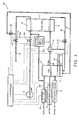
- Fig. 2 is a block diagram schematically showing a construction of a fuel cell system according to a second embodiment of the present invention.
- the construction of the second embodiment illustrates an alternation of the cathode bypass passage in the first embodiment.
- the same reference numerals as those in Fig. 1 denotes the same or corresponding parts.
- the cathode bypass valve 10 of the first embodiment (see Fig. 1), provided in the cathode bypass pipe 9 which is the cathode bypass passage, has been replaced by a dividing device 16 provided at a connecting portion 17 at which the cathode bypass pipe 9 is connected to the cathode supply pipe 7.
- the dividing device 16 allows the air flowing through an upstream cathode bypass pipe 7u to be divided into the air flowing through a downstream cathode supply pipe 7d and the air flowing through the cathode bypass pipe 9. While the dividing device 16 is used instead of the first inlet-side valve 12b (see Fig. 1) of the cathode closing device 12, the first exit-side valve 12a as the cathode exit-side closing device exists in the construction in Fig. 2.
- the combustible gas diluting device is formed by the cathode bypass pipe 9 (cathode bypass passage) connecting the portion of the cathode supply pipe 7 (portion of the oxidizing gas passage which is located upstream of the cathode 1c) to the portion of the cathode discharge pipe 8 (oxidizing gas passage) which is located downstream of the first exit-side valve 12a (second oxidizing gas passage valve), and the dividing device 16 disposed at the connecting portion 17 between the upstream portion and the cathode bypass passage 9 and configured to open and close the cathode supply pipe 7 instead of the first inlet-side valve (first oxidizing gas passage valve) 12b and to vary division ratio of the flow rate of the oxidizing gas (air) flowing through the cathode bypass pipe 9 to the flow rate of the oxidizing gas flowing through the oxidizing gas passage 8.
- a three-way valve capable of setting a desired division ratio, may be used as the dividing device 16.
- the dividing device 16 adjusts the ratio between the flow rate of the air flowing through the downstream cathode supply pipe 7d and the flow rate of the air flowing through the cathode bypass pipe 9.
- the adjustment of the division ratio made by the dividing device 16 is controlled by the controller 21.
- the fuel gas from the fuel generator 2 is supplied to the anode 1a of the fuel cell 1 through the passage switching device 14 provided in the anode supply pipe 34.
- the dividing device 16 operates so that all the air blown from the blower 5 flows to the downstream cathode supply pipe 7d to allow this air to be supplied to the cathode 1c of the fuel cell 1.
- the fuel gas (hydrogen) and the air (oxidizing gas) are consumed to generate electric power.
- the gas supply to the cathode 1c of the fuel cell 1 is controlled as described below.
- the operation of the blower 5 is stopped to stop the air supply to the cathode 1c.
- the valve which is the cathode feed gas supply device 11 is opened, and the combustible feed gas is guided to the downstream cathode supply pipe 7d through the cathode feed gas supply pipe 32 and to the cathode 1c of the fuel cell 1 through the downstream cathode pipe 7d.
- the first exit-side valve 12a is opened.
- the dividing device 16 operates so that the ratio of the flow rate of the air flowing through the cathode bypass pipe 9 to the flow rate of the air flowing through the upstream cathode supply pipe 7u is set to 1 and the ratio of the flow rate of the air flowing through the downstream cathode supply pipe 7d to the flow rate of the air flowing through the upstream cathode supply pipe 7u is set to 0.
- the first exit-side valve 12a is closed and the supply of the feed gas to the cathode 1c of the fuel cell 1 is stopped by closing the cathode feed gas supply device 11 in a case where the cathode feed gas supply device 11 is formed by a valve.
- the gas is supplied to the anode 1a of the fuel cell 1 during the stop operation of the power generation as in the first embodiment.
- the fuel gas hydrogen-rich gas
- the combustible gas feed gas
- the gas supply to the cathode 1c of the fuel cell 1 is controlled as described below.
- the first exit-side valve 12a is opened and the air starts to be supplied from the blower 5 to the cathode 1c through the cathode supply pipe 7.
- the air supplied from the blower 5 flows through a passage A in such a manner that the air flowing through the upstream cathode supply pipe 7u is divided to flow through the downstream.
- the air flowing through the passage A purges the feed gas filled in the cathode 1c to the cathode discharge pipe 8, along with the air.
- the purged feed gas is mixed with the air flowing through the passage B at a point where the cathode bypass pipe 9 is connected to the cathode discharge pipe 8.
- the combustible gas in the gas mixture is diluted to have a concentration lower than the combustion lower limit, and finally discharged to outside the fuel cell system 39 (to atmosphere).
- the flow rate of the air flowing through the passage A and the flow rate of the air flowing through the passage B are adjusted by the dividing device 16 in such a manner that a ratio between these flow rates is set so that the concentration of the combustible gas in the gas mixture discharged outside the fuel cell system 39 becomes lower than the combustion lower limit.
- the concentration of the combustible gas in the gas mixture finally discharged can be decreased to lower than 5% by setting the ratio in the dividing device 16 so that the flow rate of the air per unit time flowing through the passage B becomes more than 20 times as high as the flow rate of the air per unit time flowing through the passage A.
- the ratio in the dividing device 16 is set so that all the air supplied from the blower 5 is flowed into the downstream cathode supply pipe 7d and to the cathode 1c of the fuel cell 1, thereby enabling power generation to start.
- the gas is supplied to the anode 1a of the fuel cell 1 at the start of the power generation as in the first embodiment.
- the incombustible oxidizing gas (e.g., air) supplied from the blower 5 is divided by the dividing device 16 provided at the connecting portion 17 to flow through the passage A, i.e., from the cathode supply pipe 7 to the cathode discharge pipe 8 through the cathode 1c of the fuel cell 1, and to flow through the passage B, i.e., to the cathode discharge pipe 8 through the cathode bypass pipe 9.
- the ratio between the flow rate of the air flowing through the passage A and the flow rate of the air flowing through the passage B is adjusted by the dividing device 16.
- the air flowing through the passage A purges the combustible feed gas (e.g., city gas 13A) filled in the cathode 1c such that the feed gas is discharged into the cathode discharge pipe 8 along with the air
- the feed gas is mixed with the air flowing through the passage B so that the combustible gas in the gas mixture is diluted to have a concentration lower than the lower limit concentration, and in this diluted state, the gas mixture is discharged to atmosphere.
- the combustible gas filled in the cathode 1c can be appropriately treated.
- the feed gas can be filled and kept in the cathode 1c of the fuel cell 1.
- the combustible gas fuel gas
- the combustible gas is confined in the anode 1a. This makes it possible to completely eliminate a cause of oxidization of the catalyst in the anode 1a of the fuel cell 1, and hence to avoid reduction of durability of the anode 1a of the fuel cell system 39.
- the stop operation and keeping operation of the fuel cell system 39 are carried out under the condition in which the first exit-side valve 12a of the cathode closing device 12 is closed and the upstream cathode supply pipe 7u and the downstream cathode supply pipe 7d are fluidically disconnected, the feed gas supplied to the cathode 1c of the fuel cell 1 by the cathode feed gas supply device 11 can be reliably confined in the fuel cell 1, and if the feed gas is kept for a long time period under the stopped state of the fuel cell 1, the air will not enter the cathode 1c of the fuel cell 1. Consequently, reduction of durability of the fuel cell system 39 can be inhibited.
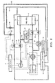
- Fig. 3 is a block diagram schematically showing a construction of a fuel cell system according to a third embodiment of the present invention.
- the piping and valve structures associated with post-treatment of the feed gas filled in the cathode 1a in the construction of the first embodiment (Fig. 1) have been altered in the construction of the third embodiment.
- the same reference numerals as those in Fig. 1 denote the same or corresponding parts, which will not be further described.
- the cathode bypass pipe 9 and the cathode bypass valve 10 (see Fig. 1) of the first embodiment have been replaced by a cathode combustion pipe 19 configured to branch from a position of the cathode discharge pipe 8 which is located upstream of the first exit-side valve 12a and to be connected to the combustor 4 (more specifically, a flame burner 41 of the combustor 4 in Fig. 4), and a combustion pipe valve 20 provided in the cathode combustion pipe 19 and configured to start and stop air supply to the cathode combustion pipe 19.
- an electromagnetic valve is used as the combustion pipe valve 20 and controlled by the controller 21.
- a combustion fan (combustion air supply device) 18 in Fig. 3 is connected to the combustor 4 and configured to supply air for heating the fuel generator 2 to the flame burner 41 of the combustor 4.
- the combustible gas diluting device is formed by the combustion fan (combustion air supply device) 18 configured to supply the air to the flame burner 41 of the combustor 4, the cathode combustion pipe 19 extending from the position of the cathode discharge pipe (oxidizing gas passage) 8 between the first exit-side valve (second oxidizing gas passage opening and losing device) 12a and the cathode 1c and connected to the flame burner 41, and the combustion pipe valve 20 configured to open and close the cathode combustion pipe 19.
- the gas supply to the cathode 1c of the fuel cell 1 is controlled as described below.
- the operation of the blower 5 is stopped to stop the air supply to the cathode 1c of the fuel cell 1.
- the feed gas containing the combustible gas flows through the cathode feed gas supply pipe 32 and is guided by the cathode feed gas supply device 11 to the portion of the cathode supply pipe 7 which is located downstream of the first inlet-side valve 12b, and to the cathode 1c of the fuel cell 1 through this portion of the cathode supply pipe 7 (corresponding to the operation of the cathode feed gas supply device 11 of the first embodiment).
- the first inlet-side and exit-side valves 12b and 12a are closed and the combustion pipe valve 20 is opened.
- the air remaining in the cathode 1c of the fuel cell 1 is purged therefrom flow through the combustion pipe valve 20 and the cathode combustion pipe 19 and discharged from the combustor 4 to outside.
- the combustion pipe valve 20 is closed and the supply of the feed gas to the cathode 1c of the fuel cell 1 is stopped by closing the cathode feed gas supply device 11.
- the gas supply to the anode 1a of the fuel cell 1 during the stop operation of power generation is similar to that of the first embodiment.
- the fuel gas (hydrogen-rich gas) is filled and kept in the anode 1a, and the combustible gas (feed gas) is filled and kept in the cathode 1c, thereby inhibiting oxidization and degradation of the anode 1a.
- the gas supply to the cathode 1c of the fuel cell 1 is controlled as described below.
- the first inlet-side valve 12b and the combustion pipe valve 20 are opened, and the first exit-side valve 12a is closed. Under this condition, the air starts to be supplied from the blower 5 to the cathode 1c of the fuel cell 1 through the cathode supply pipe 7.
- the air supplied from the blower 5 purges the combustible feed gas filled in the cathode 1c. That is, the feed gas is discharged into the cathode discharge pipe 8 along with the air flowing from the cathode supply pipe 7 to the cathode discharge pipe 8 through the cathode 1c of the fuel cell 1. Then, the discharged feed gas flows to the flame burner 41 of the combustor 4 through the combustion pipe valve 20 and the cathode combustion pipe 19.
- the cathode combustion pipe 19 is connected to a first connecting port 44 of the combustor 4 so that the gas flowing through the cathode combustion pipe 19 is guided to the flame burner 41 of the combustor 4.
- the combustion fan 18 is connected to a second connecting port 45 of the combustor 4 so that the air is guided to the flame burner 41 of the combustor 4.
- a combustion tube 40 is provided to cover the flame burner 41.
- An exhaust pipe 23 is provided on a side surface of the combustion tube 40, and the exhaust gas (gas containing nitrogen as main component) generated by combustion in the flame burner 41 is discharged to outside (atmosphere) through the exhaust pipe 23.
- An auxiliary material supply pipe 22 (see Fig.
- the feed gas filled in the cathode 1c is supplied to the flame burner 41, a combustion state is undesirably disturbed by the supply of the feed gas to the flame burner 41 if the combustion in the flame burner 41 starts before the post-treatment of the feed gas is completed. For this reason, the supply of the feed gas to the flame burner 41 starts before the combustion in the flame burner 41 starts. After all the feed gas filled in the cathode 1c has been sent to and treated in the combustor 4 and discharged to outside, the combustion in the flame burner 41 starts.
- a flame rod 42 which is capable of detecting an ion current flowing through the flame during the combustion or a thermocouple 43, is equipped in the flame burner 41, and the controller 21 monitors whether or not the flame burner 41 is conducting combustion, based on a detection signal from the flame rod 41 or the thermocouple 43.
- the feed gas filled in the cathode 1c is treated in the above constructed combustor 4.
- the feed gas filled in the cathode 1c is purged therefrom by the air supplied from the blower 5 to flow into the cathode combustion pipe 19, and is supplied to the flame burner 41 through the first connecting port 44 of the combustor 4. Simultaneously, the air from the combustion fan 18 is supplied to the flame burner 41 through the second connecting port 45.
- the feed gas flowing through the cathode combustion pipe 19 and the air from the combustion fan 18 are mixed with each other in the flame burner 41 of the combustor 4 so that the combustible gas in the gas mixture is diluted to have a concentration lower than the combustion lower limit, and then the resulting gas mixture is discharged to outside the fuel cell system 39.
- the controller 21 controls the flow rate of the blower 5 and the flow rate of the combustion fan 18 so that the concentration of the combustible gas in the flame burner 41 becomes lower than the lower limit concentration.
- the concentration of the combustible gas in the gas mixture finally discharged can be decreased to lower than 5% by controlling setting so that the flow rate of the air supplied from the combustion fan 18 becomes more than twenty times as high as the flow rate of the air supplied from the blower 5.
- an incombustible oxidizing gas e.g., air supplied from the blower 5 purges the combustible feed gas (e.g., city gas 13A) filled in the cathode 1c to the flame burner 41 of the combustor 4, along with the oxidizing gas, and the incombustible oxidizing gas (e.g., air) from the combustion fan 18 is supplied to the flame burner 41 of the combustor 4 so that these gases are mixed with each other in the combustor 4.
- combustible feed gas e.g., city gas 13A
- the combustible gas in the gas mixture can be diluted to have a concentration lower than the combustion lower limit concentration, and in this diluted state, the gas mixture can be discharged to atmosphere. In this manner, the combustible gas filled in the cathode 1c can be appropriately post-treated.
- the feed gas is confined in the cathode 1c of the fuel cell 1.
- the combustible gas fuel gas
- the combustible gas is filled and confined in the anode 1a. This makes it possible to completely eliminate a cause of oxidization of the catalyst in the anode 1a of the fuel cell 1, and hence to avoid reduction of durability of the anode 1a of the fuel cell system 39.
- the stop operation and keeping operation of the fuel cell system 39 are carried out with the first exit-side and inlet-side valves 12a and 12b of the cathode closing device 12 closed and the combustion pipe valve 20 closed, the feed gas supplied to the cathode 1c of the fuel cell 1 by the cathode feed gas supply device 11 can be reliably confined in the fuel cell 1, and if the feed gas is kept for a long time period under the stopped state of the fuel cell 1, the air will not enter the cathode 1c of the fuel cell 1. Consequently, reduction of durability of the fuel cell system 39 can be inhibited.
- Fig. 5 is a block diagram schematically showing a construction of a fuel cell system according to a fourth embodiment of the present invention.
- the fourth embodiment illustrates an alternation of the piping in the third embodiment.
- the same reference numerals as those in Fig. 3 denote the same or corresponding parts, which will not be further described:
- the cathode combustion pipe 19 (see Fig. 3 of the third embodiment) connecting the portion of the cathode discharge pipe 8 which is located upstream of the first exit-side valve 12a to the combustor 4 has been replaced by a cathode exhaust pipe 25 extending from a position of the cathode discharge pipe 8 which is located upstream of the first exit-side valve 12a and connected to the exhaust pipe 23 (see Fig. 4), and an exhaust pipe valve 26 is provided in the cathode exhaust pipe 25 and configured to control start and stop of the air supply.
- the cathode feed gas supply pipe 32 (see Fig.
- the combustible gas diluting device is formed by the exhaust pipe 23 through which the exhaust gas generated by combustion in the combustor 4 is discharged to atmosphere, the cathode exhaust pipe 25 extending from a position of the cathode discharge pipe (oxidizing passage) 8 which is the oxidizing gas passage between the first exit-side valve (second oxidizing gas passage valve) 12a and the cathode 1c and connected to the flame burner 41, and the exhaust pipe valve 26 configured to open and close the cathode exhaust pipe 25.
- the feed gas supplied from the feed gas supply device 36 and the water supplied from the water supply device 3 are reformed within the fuel generator 2 to generate a hydrogen-rich fuel gas, with the temperature of the fuel generator 2 kept at approximately 700°C.
- the fuel gas from the fuel generator 2 flows through the passage switching device 14 provided in the anode supply pipe 34, and is supplied to the anode 1a of the fuel cell 1 (under the condition in which the passage switching device 14 allows communication between the anode supply pipe 34 and the anode 1a).
- the air from the blower 5 is supplied to the cathode 1c of the fuel cell 1 through the cathode supply pipe 7 and the first inlet-side valve 12b in an open position.
- the fuel gas (hydrogen) and the air (oxidizing gas) are consumed to generate electric power.
- the fuel gas unconsumed in the power generation of the fuel cell 1 is sent to the combustor 4 through the fuel gas return pipe 35 and the return pipe valve 15 in an open position, and combusted therein to produce a heat source for keeping the temperature of the fuel generator 2. If the remaining fuel gas from the fuel cell 1 is insufficient to keep the temperature of the fuel generator 2 appropriately, then the feed gas is additionally supplied to the flame burner 41 of the combustor 4 through the auxiliary material supply pipe 22, and the air is supplied from the combustion fan 18 to the flame burner 41 while adjusting the flow rate of the air to allow the added feed gas to be stably combusted. Meanwhile, the air unconsumed in the power generation of the fuel cell 1 is discharged to atmosphere through the cathode discharge pipe 8 and the first exit-side valve 12a in an open position.
- the gas supply to the cathode 1c of the fuel cell 1 is controlled as described below.
- the operation of the blower 5 is stopped to stop the air supply to the cathode 1c of the fuel cell 1.
- the cathode fuel supply device 24 operates to guide the fuel gas containing the combustible gas to the portion of the cathode supply pipe 7 which is located downstream of the first inlet ⁇ side valve 12b through the cathode fuel supply pipe 49, and to the cathode 1c of the fuel cell 1 through the cathode supply pipe 7.
- the exit-side and inlet-side valves 12a and 12b are closed and the exhaust pipe valve 26 is opened.
- the fuel gas supplied to the cathode 1c purges the air remaining in the cathode 1c of the fuel cell 1 through the exhaust pipe valve 26 and the cathode exhaust pipe 25 to the exhaust pipe 23, from which the air and the fuel gas are discharged.
- the exhaust pipe valve 26 is closed, and the supply of the fuel gas to the cathode 1c of the fuel cell 1 is stopped by closing the cathode fuel supply device 24.
- the fuel gas existing just after the exit of the fuel generator 2 has an increased pressure.
- the valve which is the cathode fuel supply device 24 located in the cathode fuel supply pipe 49 With one end of the cathode fuel supply pipe 49 connected to the anode supply pipe 34 just after the exit of the fuel generator 2 and the other end connected to the portion of the cathode supply pipe 7 which is located downstream of the first inlet-side valve 12b, the fuel gas can be guided to the portion of the cathode supply pipe 7 which is located downstream of the first inlet-side valve 12b and to the cathode 1c by utilizing an internal pressure of the fuel gas. If the pressure of the fuel gas being supplied is deficient, the fuel gas may be supplied to the cathode 1c under pressure by using a feed pump as the cathode fuel supply device 24.
- the hydrogen-rich gas e.g., gas having a content of 80% hydrogen
- the hydrogen-rich gas gas having a content of 80% hydrogen
- the gas supply to the anode 1a of the fuel cell 1 in the stop operation is performed as in the first embodiment.
- the fuel gas (hydrogen-rich gas) is filled and kept in the anode 1a, and the combustible gas (hydrogen-rich fuel gas) is filled and kept in the cathode 1c, thus inhibiting oxidization and degradation in the anode 1a.
- the gas supply to the cathode 1c of the fuel cell 1 is controlled as described below.
- the first inlet-side valve 12b and the exhaust pipe valve 26 are opened and the first exit ⁇ side valve 12a is closed.
- the air starts to be supplied from the blower 5 to the cathode 1c through the cathode supply pipe 7.
- the oxidizing gas (air) supplied from the blower 5 purges the combustible fuel gas filled in the cathode 1c.
- the fuel gas is discharged to the cathode discharge pipe 8 along with the air flowing from the cathode supply pipe 7 into the cathode discharge pipe 8 through the cathode 1c of the fuel cell 1.
- the discharged fuel gas flows to the exhaust pipe 23 through the exhaust pipe valve 26 and the cathode exhaust pipe 25.
- the fuel gas filled in the cathode 1c is guided to the exhaust pipe 23.
- the fuel gas can be supplied to the exhaust pipe 23 during a combustion period of the flame burner 41, and mixed with the exhaust gas containing incombustible nitrogen as main component in the exhaust pipe 23 so that the combustible gas in the gas mixture is diluted to have a concentration lower than the combustion lower limit, and discharged to atmosphere. Therefore, in the post-treatment of the fuel gas in the exhaust pipe 23, it is not necessary to delay a start time of combustion in the flame burner 41 as compared to the third embodiment, and a process of the post-treatment of the fuel gas can be simplified.
- the controller 21 controls the flow rate of the oxidizing gas (air) supplied from the blower 5 and the flow rate of the exhaust gas generated in the flame burner 41 so that the concentration of the combustible gas in the exhaust pipe 23 becomes lower than the combustion lower limit.
- the concentration of the combustible gas in the gas mixture finally discharged can be decreased to lower than 4% by controlling setting so that the flow rate of the air supplied from the blower 5 becomes lower than 1/25 as much as the amount of the exhaust gas generated by the combustion in the flame burner 41.
- the incombustible oxidizing gas (e.g., air) supplied from the blower 5 purges the combustible fuel gas (e.g., hydrogen-rich gas) filled in the cathode 1c to the exhaust pipe 23, and the exhaust gas mainly containing nitrogen generated in the combustion of the flame burner 41 of the combustor 4 is guided to the exhaust pipe 23 to allow these gases to be mixed therein.
- the combustible gas in the gas mixture can be diluted to have a concentration lower than the combustion lower limit, and in this diluted state, the gas mixture can be discharged to atmosphere. In this manner, the combustible gas filled in the cathode 1c can be appropriately treated.
- the fuel gas is confined in the cathode 1c of the fuel cell 1.
- the combustible gas is filled in the anode 1a. This makes it possible to completely eliminate a cause of oxidization of the catalyst in the anode 1a of the fuel cell 1, and hence to avoid reduction of durability of the anode 1a of the fuel cell system 39.
- the stop operation and keeping operation of the fuel cell system 39 are carried out with the first exit-side and inlet-side valves 12a and 12b of the cathode closing device 12 closed and the exhaust pipe valve 26 closed, the fuel gas supplied to the cathode 1c of the fuel cell 1 by the cathode fuel supply device 24 can be reliably confined in the fuel cell 1, and if the fuel gas is kept for a long time period under the stopped state of the fuel cell 1, the air will not enter the cathode 1c of the fuel cell 1. Consequently, reduction of durability of the fuel cell system 39 can be inhibited.
- Fig. 6 is a block diagram schematically showing a construction of a fuel cell system according to a fifth embodiment of the present invention.
- the fifth embodiment illustrates an alternation of piping of the cathode exhaust pipe in the fourth embodiment.
- the same reference numerals as those in Fig. 5 denote the same or corresponding parts, which will not be further described.
- FIG. 6 the construction (see Fig. 5 of the fourth embodiment) in which the cathode exhaust pipe 25 branching from a position of the cathode discharge pipe 8 which is located upstream of the first exit-side valve 12a and connected to the exhaust pipe 23 has been replaced by the construction in which the cathode discharge pipe 8 which is the oxidizing gas passage is directly connected to the exhaust pipe 23.
- the exhaust pipe valve 26 provided in the cathode exhaust pipe 25 and configured to control start and stop of the air supply to the cathode exhaust pipe 25 has been eliminated in the construction of Fig. 6. Since the exhaust pipe valve 26 or the cathode exhaust pipe 25 can be omitted, the gas supply pipe system can be simplified as compared to the fourth embodiment.
- the combustible gas diluting device is formed by connecting the exhaust pipe 23 through which the exhaust gas generated by the combustion in the combustor 4 is guided to atmosphere to the portion of the cathode discharge pipe (oxidizing gas passage) 8 which is located downstream of the first exit-side valve (second oxidizing gas passage valve) 12a.
- the gas supply to the cathode 1c of the fuel cell 1 is controlled as described below.
- the cathode fuel supply device 24 guides the fuel gas containing the combustible gas to the portion of the cathode supply pipe 7 which is located downstream of the inlet-side valve 12b through the cathode fuel supply pipe 49, and to the cathode 1c of the fuel cell 1 through the cathode supply pipe 7.
- the first inlet-side valve 12b is closed and the first exit-side valve 12a is opened.
- the fuel gas supplied to the cathode 1c purges the air remaining in the cathode 1c of the fuel cell 1 through the first exit-side valve 12a and the cathode discharge pipe 8, and the air is discharged outside from the exhaust pipe 23.
- the first exit-side valve 12a is closed and the supply of the fuel gas to the cathode 1c of the fuel cell 1 is stopped by closing the cathode fuel supply device 24.
- the hydrogen-rich gas e.g., gas having a content of 80% hydrogen
- the hydrogen-rich gas gas having a content of 80% hydrogen
- the gas is supplied to the anode 1a of the fuel cell 1 in the stop operation as in the first embodiment.
- the fuel gas (hydrogen-rich gas) is filled and kept in the anode 1a, and the combustible gas (hydrogen-rich fuel gas) is filled and kept in the cathode 1c, thereby inhibiting oxidization and degradation of the anode 1a.
- the gas supply to the cathode 1c of the fuel cell 1 is controlled as described below.
- the first inlet-side valve 12b and the first exit-side valve 12a are closed. Under this condition, the air starts to be supplied from the blower 5 to the cathode 1c through the cathode supply pipe 7.
- the oxidizing gas (air) supplied from the blower 5 purges the combustible fuel gas filled in the cathode 1c into the cathode discharge pipe 8. That is, the fuel gas is discharged into the exhaust pipe 23 through the cathode discharge pipe 8 along with the air flowing from the cathode supply pipe 7 to the cathode discharge pipe 8 through the cathode 1c of the fuel cell 1.
- the treatment of the combustible gas (fuel gas) filled in the cathode 1c in the exhaust pipe 23 is identical to that of the fourth embodiment.
- the incombustible oxidizing gas (e.g., air) supplied from the blower 5 purges the combustible fuel gas (e.g., hydrogen-rich fuel gas) filled in the cathode 1c into the exhaust pipe 23, and the exhaust gas mainly containing nitrogen generated in the combustion of the flame burner 41 of the combustor 4 is guided to the exhaust pipe 23 to allow these gases to be mixed therein.
- the combustible gas in the gas mixture can be diluted to have a concentration lower than the combustion lower limit, and in this diluted state, the gas mixture can be discharged to atmosphere. In this manner, the combustible gas filled in the cathode 1c can be appropriately post-treated.
- the fuel gas is filled and kept in the cathode 1c of the fuel cell 1.
- the combustible gas is filled in the anode 1a. This makes it possible to completely eliminate a cause of oxidization of the catalyst in the anode 1a of the fuel cell 1, and hence to avoid reduction of durability of the anode 1a of the fuel cell system 39.
- the stop operation and keeping operation of the fuel cell system 39 is carried out with the first exit-side and inlet-side valves 12a and 12b of the cathode closing device 12 closed, the fuel gas supplied to the cathode 1c of the fuel cell 1 by the cathode fuel supply device 24 can be reliably confined in the fuel cell 1, and if the fuel gas is kept for a long time period under the stopped state of the fuel cell 1, the air will not enter the cathode 1c of the fuel cell 1. Consequently, reduction of durability of the fuel cell system 39 can be inhibited.
- Fig. 7 is a block diagram schematically showing a construction of a fuel cell system according to a six embodiment of the present invention.
- the sixth embodiment illustrates an alternation of gas supply system of the fuel cell system 39 of the first embodiment.
- the same reference numerals as those in Fig. 1 denote the same or corresponding parts, which will not be further described.
- the fuel cell system 39 comprises a polymer electrolyte fuel cell 1, a hydrogen supply device 47, a hydrogen return pump 29, an anode closing device 30, a blower 5, a cathode bypass pipe (cathode bypass passage) 9, a cathode bypass valve 10, a cathode closing device 12, and a cathode hydrogen supply device (combustible gas supply device) 31.
- the fuel cell 1 is configured to generate electric power using hydrogen and an oxidizing gas (air).
- the hydrogen supply device 47 includes a hydrogen tank 27 that stores hydrogen as a fuel gas and a hydrogen supply pump 28 which pumps to supply hydrogen from the hydrogen tank 27 to the anode 1a of the fuel cell 1 through the hydrogen supply pipe 37.
- the hydrogen return pump 29 is configured to pump to cause remaining hydrogen exhausted from the anode 1a to a hydrogen exhaust pipe 38 to return to the fuel cell 1.
- the anode closing device 30 includes a second inlet-side valve 30a and a second exit-side valve 30b configured to open and close inlet and exit of the anode 1a of the fuel cell 1.
- the blower 5 is configured to supply the air which is the oxidizing gas to the cathode 1c of the fuel cell 1 through the cathode supply pipe 7 which is the oxidizing gas passage and to discharge the remaining air from the cathode 1c to the cathode discharge pipe 8 which is the oxidizing gas passage.
- the air supplied from the blower 5 is guided into the cathode discharge pipe 8 through the cathode bypass pipe (cathode bypass passage) 9 without flowing through the fuel cell 1.
- the cathode bypass valve 10 is provided in the cathode bypass pipe 9 and configured to open and close the pipe 9.
- the cathode closing device 12 includes a first inlet-side valve (first oxidizing gas passage valve) 12b and a first exit-side valve (second oxidizing gas passage valve) 12a configured to open and close an inlet and an exit of the cathode 1c of the fuel cell 1.
- the cathode hydrogen supply device 31 is configured to supply hydrogen to the cathode 1c of the fuel cell 1 through a cathode hydrogen supply pipe 48.
- the combustible gas diluting device is formed by the cathode bypass pipe (cathode bypass passage) 9 connecting the portion of the cathode supply pipe 7 which is located upstream of the first-inlet side valve (first oxidizing gas passage valve) 12b to the portion of the cathode discharge pipe (oxidizing gas passage) 8 which is located downstream of the first exit-side valve (second oxidizing gas passage valve) 12a, and the cathode bypass valve 10 configured to open and close the cathode bypass pipe 9.
- the cathode bypass valve 10, the first exit-side and inlet-side valves 12a and 12b of the cathode closing device 12, the second inlet-side and exit-side valves 30a and 30b of the anode closing device 30 are formed by, for example, electromagnetic valves, and the cathode hydrogen supply device 31 is formed by, for example, a valve or a pump.
- the controller 21 is electrically connected to the blower 5, the hydrogen supply pump 28, the hydrogen return pump 29, the cathode hydrogen supply device 31, and the valves 10, 12a, 12b, 30a, and 30b and configured to control these components to properly control the fuel cell system 39 to be described later.
- the components to be controlled by the controller 21 are indicated by a dashed line in Fig. 7.
- hydrogen stored in the hydrogen tank 27 is supplied by the hydrogen supply pump 28 to the anode 1a of the fuel cell 1 through the hydrogen supply pipe 37, and hydrogen unconsumed in the anode 1a of the fuel cell 1 is exhausted into the hydrogen exhaust pipe 38 and retuned to the anode 1a of the fuel cell 1 by the hydrogen return pump 29 provided in the hydrogen exhaust pipe 38.
- the second inlet-side and exit-side valves 30a and 30b are opened.
- the air from the blower 5 is supplied from the blower 5 to the cathode 1c of the fuel cell 1 through the cathode supply pipe 7, and the air unconsumed in the cathode 1c is discharged to atmosphere through the cathode discharge pipe 8.
- the first exit-side and inlet-side valves 12a and 12b are opened.
- the gas supply to the cathode 1c of the fuel cell 1 is controlled as described below.
- the operation of the blower 5 is stopped to stop the air supply to the cathode 1c of the fuel cell 1.
- the power generation in the fuel cell 1 stops.
- the cathode hydrogen supply device 31 guides the combustible hydrogen to the portion of the cathode supply pipe 7 which is located downstream of the first inlet-side valve 12b through the cathode hydrogen supply pipe 48, and to the cathode 1c of the fuel cell 1 through this portion of the cathode supply pipe 7.
- the first inlet-side valve 12b is closed and the first exit-side valve 12a is opened.
- the first exit-side valve 12a of the cathode closing device 12 is closed and the supply of hydrogen to the cathode 1c of the fuel cell 1 is stopped by closing the cathode hydrogen supply device 31 in a case where the cathode hydrogen supply device 31 is formed by a valve.
- the hydrogen existing just after the exit of the hydrogen supply pump 28 has an increased pressure.
- the valve which is the cathode hydrogen supply device 31 in the cathode hydrogen supply pipe 48 With one end of the cathode hydrogen supply pipe 48 connected to the hydrogen supply pipe 37 just after the exit of the hydrogen supply pump 28 and the other end thereof connected to the portion of the cathode supp pipe 7 which is located downstream of the first inlet-side valve 12b, hydrogen can be guided to the portion of the cathode supply pipe 7 which is located downstream of the first inlet-side valve 12b and to the cathode 1c by utilizing an internal pressure of hydrogen. If the pressure of the hydrogen being supplied is deficient, hydrogen may be supplied to the cathode 1c under pressure by using a feed pump as the cathode hydrogen supply device 31.
- the controller 21 determines the flow rate of hydrogen which can purge almost all the air based on the amount of remaining air.
- the second exit-side and inlet-side valves 30b and 30a of the anode closing device 30 are closed to confine the hydrogen in the anode 1a of the fuel cell 1, and then, the operations of the hydrogen supply pump 28 and the hydrogen return pump 29 are stopped.
- the gas supply to the cathode 1c of the fuel cell 1 is controlled as described below.
- the first inlet-side and exit-side valves 12b and 12a of the cathode closing device 12 and the cathode bypass valve 10 are all opened, and the air starts to be supplied from the blower 5 to the cathode 1c through the cathode supply pipe 7.
- the air supplied from the blower 5 flows through a passage A, i.e., from the cathode supply pipe 7 to the cathode discharge pipe 8 through the cathode 1c of the fuel cell 1 and a passage B, i.e., from the cathode supply pipe 7 to the cathode bypass pipe 9 to flow through the cathode bypass valve 10.
- the air flowing through the passage A purges hydrogen filled in the cathode 1c, and these gases are discharged into the cathode discharge pipe 8.
- the hydrogen is mixed with the air flowing through the passage B at a point where the cathode discharge pipe 8 is connected to the cathode bypass pipe 9 so that the combustible gas in the gas mixture is diluted to have a concentration lower than the combustion lower limit, and the resulting gas mixture is discharged outside (to atmosphere) of the fuel cell system 39.
- the flow rate of the air flowing through the passage A and the flow rate of the air flowing through the passage B are adjusted according to passage resistances described below.
- the flow rates are set so that the concentration of the combustible gas in the gas mixture discharged outside the fuel cell system 39 becomes lower than the combustion lower limit.
- the concentration of the combustible in the gas mixture finally discharged becomes lower than 4% by setting the flow rate of the air per unit time flowing through the passage B becomes more than 25 times as high as the flow rate of the air per unit time flowing through the passage A.
- (flow rate per unit time of the passage B) / (flow rate per unit time of the passage A) > 25 can be set by adjusting, for example, an aperture diameter of the valve which is the cathode bypass valve 10 to thereby control the passage resistance of the passage B.
- the cathode bypass valve 10 is closed, and the air is supplied from the blower 5 only to the cathode 1c of the fuel cell 1, thereby enabling power generation to start.
- the dividing device 16 of the second embodiment may be used in the sixth embodiment instead of the cathode bypass valve 10. Specifically, as shown in the portion represented by the dotted line in Fig. 7, the dividing device 16 is provided at the connecting portion 17 between the cathode bypass pipe 9 and the cathode supply pipe 7, instead of the cathode bypass valve 10 in the cathode bypass pipe 9.
- the dividing device 16 is capable of dividing the gas flowing through the upstream cathode bypass pipe 7u into the gas flowing through the downstream cathode supply pipe 7d and the gas flowing through the cathode bypass pipe 9. Also, while the.
- first inlet-side valve 12b of the cathode closing device 12 is replaced by the dividing device 16, the first exit-side valve 12a which is the cathode exit closing device exists.
- the dividing device 16 adjusts the ratio between the flow rate of the gas flowing through the downstream cathode supply pipe 7d and the flow rate of the gas flowing through the cathode bypass pipe 9 downstream of the connecting portion 17.
- the adjustment of the ratio made by the dividing device 16 is controlled by the controller 21.
- mixing and dilution of the gas (hydrogen) filled in the cathode 1c and air or the exhaust gas may be conducted as in the operation of the third and fifth embodiments. For example, as shown in alternations in Fig.
- the cathode combustion pipe 19 branching from a position of the cathode discharge pipe 8 may be connected to the flame burner 41 of the combustor 4, and the combustion pipe valve 20 may be provided in the cathode combustion pipe 19 (corresponding to the construction in the third embodiment), the cathode exhaust pipe 25 branching from a position of the cathode discharge pipe 8 may be connected to the exhaust pipe 23 and the exhaust pipe valve 26 may be provided in the cathode exhaust pipe 25 (corresponding to a fourth embodiment), or the cathode discharge pipe 8 may be directly connected to the exhaust pipe 23 (corresponding to the fifth embodiment), so that hydrogen filled in the cathode 1c is mixed with incombustible gas in the combustor 4 or the exhaust pipe 23 to be diluted, and the resulting gas mixture is discharged to atmosphere.
- the second exit-side and inlet-side valves 30a and 30b of the anode closing device 30 are opened, and then the operation of the hydrogen supply pump 28 and the operation of the hydrogen return pump 29 start.
- the incombustible oxidizing gas e.g., air
- the passage A i.e., from the cathode supply pipe 7 to the cathode discharge pipe 8 through the fuel cell 1 and the passage B, i.e., to the cathode bypass pipe 9 provided with the cathode bypass valve 10.
- the passages A and B set to have predetermined resistances, the air flows therethrough.
- the air flowing through the passage A purges the combustible hydrogen filled in the cathode 1c into the cathode discharge pipe 8 so that the combustible gas in the gas mixture is diluted to have a concentration lower than a combustion lower limit, and the diluted gas mixture is discharged to atmosphere.
- the stop operation and keeping operation of the fuel cell system 39 is carried out with the first inlet-side and exit-side valves 12b and 12a of the cathode closing device 12 closed, hydrogen supplied to the cathode 1c of the fuel cell 1 by the cathode hydrogen supply device 31 can be confined in the fuel cell 1, and if hydrogen is kept for a long time period under the stopped state of the fuel cell 1, the air will not enter the cathode 1c of the fuel cell 1. Consequently, reduction of durability of the fuel cell system 39 can be inhibited.
- the feed gas supplied from the feed gas supply device 36 to the anode 1a is used as the combustible gas filled in the cathode 1c (first, second and third embodiments: Figs, 1, 2, and 3), the fuel gas produced from the feed gas in the fuel generator 2 (hydrogen-rich gas having a content of about 80% hydrogen) is used as the combustible gas filled in the cathode 1c in the fourth and fifth embodiments (Figs. 5 and 6), and hydrogen (pure hydrogen having a content of 100% hydrogen) supplied from the hydrogen supply device 47 to the anode 1a in the sixth embodiment (Fig. 7) is used as the combustible gas filled in the cathode 1c.
- one of the feed gas and the fuel gas may be suitably selected according to a change in predetermined piping. It is desirable to fill and keep hydrogen in a high concentration, for the purpose of improving durability of platinum catalyst. Nonetheless, the hydrogen must be treated carefully when hydrogen which has a combustion concentration range wider than those of other gases is discharged to atmosphere.
Landscapes
- Life Sciences & Earth Sciences (AREA)
- Engineering & Computer Science (AREA)
- Manufacturing & Machinery (AREA)
- Sustainable Development (AREA)
- Sustainable Energy (AREA)
- Chemical & Material Sciences (AREA)
- Chemical Kinetics & Catalysis (AREA)
- Electrochemistry (AREA)
- General Chemical & Material Sciences (AREA)
- Fuel Cell (AREA)
Applications Claiming Priority (2)
| Application Number | Priority Date | Filing Date | Title |
|---|---|---|---|
| JP2003414301A JP4354792B2 (ja) | 2003-12-12 | 2003-12-12 | 燃料電池発電装置 |
| JP2003414301 | 2003-12-12 |
Publications (3)
| Publication Number | Publication Date |
|---|---|
| EP1542303A2 true EP1542303A2 (fr) | 2005-06-15 |
| EP1542303A3 EP1542303A3 (fr) | 2009-03-04 |
| EP1542303B1 EP1542303B1 (fr) | 2012-02-08 |
Family
ID=34510557
Family Applications (1)
| Application Number | Title | Priority Date | Filing Date |
|---|---|---|---|
| EP04029352A Ceased EP1542303B1 (fr) | 2003-12-12 | 2004-12-09 | Système de pile à combustible |
Country Status (4)
| Country | Link |
|---|---|
| US (2) | US20050129990A1 (fr) |
| EP (1) | EP1542303B1 (fr) |
| JP (1) | JP4354792B2 (fr) |
| CN (1) | CN100444441C (fr) |
Cited By (3)
| Publication number | Priority date | Publication date | Assignee | Title |
|---|---|---|---|---|
| WO2015139794A1 (fr) * | 2014-03-18 | 2015-09-24 | Volkswagen Ag | Dispositif de pile à combustible équipé d'une voie de gaz de balayage |
| WO2017089010A1 (fr) * | 2015-11-23 | 2017-06-01 | Robert Bosch Gmbh | Pile à combustible |
| US10978725B2 (en) | 2014-12-03 | 2021-04-13 | Intelligent Energy Limited | Control valve, fuel cell exhaust assembly and fuel cell |
Families Citing this family (20)
| Publication number | Priority date | Publication date | Assignee | Title |
|---|---|---|---|---|
| JP4354792B2 (ja) * | 2003-12-12 | 2009-10-28 | パナソニック株式会社 | 燃料電池発電装置 |
| US20080038599A1 (en) * | 2004-11-08 | 2008-02-14 | Masataka Ozeki | Fuel Cell System |
| US8597848B2 (en) * | 2005-10-21 | 2013-12-03 | Toyota Jidosha Kabushiki Kaisha | Fuel cell system, estimation device of amount of anode gas to be generated and estimation method of amount of anode gas to be generated |
| JP5044969B2 (ja) * | 2006-04-07 | 2012-10-10 | トヨタ自動車株式会社 | 燃料電池運転システム及び燃料電池運転システムにおける弁の凍結防止方法 |
| JP5366801B2 (ja) * | 2007-03-14 | 2013-12-11 | パナソニック株式会社 | 燃料電池システム、及び燃料電池システムの運転方法 |
| US7955744B2 (en) * | 2007-06-14 | 2011-06-07 | GM Global Technology Operations LLC | Method for fuel cell start-up with uniform hydrogen flow |
| US20090246566A1 (en) * | 2008-04-01 | 2009-10-01 | Craft Jr Thomas F | Fuel cell cabinet heat management and thermal control system |
| KR101181839B1 (ko) * | 2010-06-29 | 2012-09-11 | 삼성에스디아이 주식회사 | 연료 전지 시스템 및 그 구동 방법 |
| WO2012132181A1 (fr) * | 2011-03-30 | 2012-10-04 | パナソニック株式会社 | Système de pile à combustible et son procédé d'exploitation |
| WO2012140741A1 (fr) * | 2011-04-12 | 2012-10-18 | 株式会社Eneosセルテック | Système de pile à combustible et procédé d'arrêt de celle-ci |
| JP5783974B2 (ja) * | 2012-08-28 | 2015-09-24 | 本田技研工業株式会社 | 燃料電池システムの起動方法および燃料電池システム |
| CA2902862C (fr) * | 2013-03-15 | 2019-07-16 | Exxonmobil Research And Engineering Company | Integration de piles a combustible a carbonate fondu pour la synthese de composes azotes |
| WO2014151193A2 (fr) * | 2013-03-15 | 2014-09-25 | Exxonmobil Research And Engineering Company | Génération d'énergie intégrée et production d'énergie chimique au moyen de piles à combustible |
| AU2014324641B2 (en) * | 2013-09-30 | 2017-01-05 | Exxonmobil Research And Engineering Company | Cathode combustion for enhanced fuel cell syngas production |
| JP6349710B2 (ja) * | 2013-12-12 | 2018-07-04 | 株式会社デンソー | 燃料電池システム |
| JP7078122B2 (ja) * | 2018-09-12 | 2022-05-31 | 日産自動車株式会社 | 燃料電池システム |
| FR3087136B1 (fr) * | 2018-10-12 | 2021-12-31 | Suez Groupe | Procede et dispositif de gestion d'un dispositif de traitement de gaz vicie |
| CN109950577B (zh) * | 2019-03-18 | 2020-12-11 | 东莞众创新能源科技有限公司 | 供氧系统的计算方法及应用方法 |
| FR3123511B1 (fr) * | 2021-05-28 | 2024-02-09 | Symbio | Pile a combustible et procede de purge |
| DE102022128711A1 (de) | 2022-10-28 | 2024-05-08 | MTU Aero Engines AG | Flugzeug-Brennstoffzellen-Antrieb |
Citations (8)
| Publication number | Priority date | Publication date | Assignee | Title |
|---|---|---|---|---|
| EP0374368A1 (fr) | 1988-12-22 | 1990-06-27 | International Fuel Cells Corporation | Installation de productions d'énergie de piles à combustible |
| JPH05307970A (ja) | 1992-04-30 | 1993-11-19 | Aqueous Res:Kk | 液体燃料電池 |
| EP0642184A2 (fr) | 1993-07-09 | 1995-03-08 | Ishikawajima-Harima Heavy Industries Co., Ltd. | Méthode à commande de la pression différentielle pour réformeur à plaques d'un système de piles à combustible générateur de courant |
| WO2000039877A1 (fr) | 1998-12-23 | 2000-07-06 | International Fuel Cells, Llc | Anode purgee, pile a faible combustible effluent |
| US20020122966A1 (en) | 2001-03-02 | 2002-09-05 | Acker William P. | Cold start and temperature control method and apparatus for fuel cell system |
| US20020142200A1 (en) | 2001-03-28 | 2002-10-03 | Volker Formanski | Fuel cell system and method of operating a fuel cell system |
| EP1291948A1 (fr) | 2000-06-14 | 2003-03-12 | Matsushita Electric Industrial Co., Ltd. | Systeme de generation de puissance a pile a combustible et procede d'interruption de la generation de puissance d'une pile a combustible |
| US20030194590A1 (en) | 2002-04-15 | 2003-10-16 | Joseph Cargnelli | System and method for management of gas and water in fuel cell system |
Family Cites Families (37)
| Publication number | Priority date | Publication date | Assignee | Title |
|---|---|---|---|---|
| US3539395A (en) * | 1966-02-25 | 1970-11-10 | Gen Electric | System and process for the indirect electrochemical combination of air and a reformable fuel |
| JPS54144936A (en) | 1978-05-04 | 1979-11-12 | Fuji Electric Co Ltd | Method of resting fuel battery |
| JPS61233976A (ja) * | 1985-04-10 | 1986-10-18 | Fuji Electric Co Ltd | 燃料電池設備 |
| JPS62190660A (ja) * | 1986-02-17 | 1987-08-20 | Mitsubishi Electric Corp | 燃料電池発電プラントの休止方法 |
| JPS63259971A (ja) | 1987-04-17 | 1988-10-27 | Fuji Electric Co Ltd | 燃料電池設備 |
| JPS63259972A (ja) | 1987-04-17 | 1988-10-27 | Fuji Electric Co Ltd | 燃料電池設備 |
| US4743517A (en) * | 1987-08-27 | 1988-05-10 | International Fuel Cells Corporation | Fuel cell power plant with increased reactant pressures |
| JPH03400A (ja) | 1989-05-26 | 1991-01-07 | Ishikawajima Harima Heavy Ind Co Ltd | 安全弁の保護装置 |
| JPH06140065A (ja) * | 1992-09-08 | 1994-05-20 | Toshiba Corp | 燃料電池発電システム |
| JP3192517B2 (ja) | 1993-03-17 | 2001-07-30 | 東京瓦斯株式会社 | 燃料電池発電装置 |
| JPH09298065A (ja) | 1996-05-01 | 1997-11-18 | Nippon Telegr & Teleph Corp <Ntt> | 燃料電池発電装置 |
| JPH09306522A (ja) | 1996-05-08 | 1997-11-28 | Kansai Electric Power Co Inc:The | 燃料電池発電装置用窒素製造設備 |
| US6007931A (en) * | 1998-06-24 | 1999-12-28 | International Fuel Cells Corporation | Mass and heat recovery system for a fuel cell power plant |
| DE69924682T2 (de) * | 1998-09-09 | 2005-09-29 | Matsushita Electric Industrial Co., Ltd., Kadoma | Vorrichtung zur Herstellung von Wasserstoff |
| BR9913672A (pt) * | 1998-09-14 | 2001-10-09 | Questair Technologies Inc | Sistema de geração de corrente elétrica |
| US6331366B1 (en) * | 1999-06-23 | 2001-12-18 | International Fuel Cells Llc | Operating system for a fuel cell power plant |
| WO2001047801A1 (fr) | 1999-12-28 | 2001-07-05 | Daikin Industries, Ltd. | Dispositif modificateur |
| JP2001189165A (ja) | 2000-01-05 | 2001-07-10 | Daikin Ind Ltd | 燃料電池システム、該燃料電池システムの停止方法及び立ち上げ方法 |
| US6368737B1 (en) * | 2000-07-13 | 2002-04-09 | Utc Fuel Cells, Llc | Subambient pressure coolant loop for a fuel cell power plant |
| US6521204B1 (en) | 2000-07-27 | 2003-02-18 | General Motors Corporation | Method for operating a combination partial oxidation and steam reforming fuel processor |
| JP4632501B2 (ja) | 2000-09-11 | 2011-02-16 | 大阪瓦斯株式会社 | 燃料電池の停止保管方法 |
| JP2002124278A (ja) | 2000-10-17 | 2002-04-26 | Honda Motor Co Ltd | 燃料電池システム |
| JP3975672B2 (ja) | 2000-11-17 | 2007-09-12 | 松下電器産業株式会社 | 燃料電池発電装置 |
| EP1296402A1 (fr) * | 2001-09-25 | 2003-03-26 | Ballard Power Systems AG | Système à cellules à combustible et méthode de mise en oeuvre |
| EP1298751A3 (fr) * | 2001-09-27 | 2006-04-26 | Matsushita Electric Industrial Co., Ltd. | Pile à combustible à électrolyte polymère et son procédé de fabrication |
| JP3904191B2 (ja) * | 2001-10-23 | 2007-04-11 | 本田技研工業株式会社 | 排出燃料希釈器および排出燃料希釈式燃料電池システム |
| JP2003282114A (ja) | 2002-03-26 | 2003-10-03 | Fuji Electric Co Ltd | 燃料電池発電装置の停止方法 |
| US6896982B2 (en) * | 2002-05-30 | 2005-05-24 | Ballard Power Systems Inc. | Conditioning method for fuel cells |
| US6835479B2 (en) | 2002-06-26 | 2004-12-28 | Utc Fuel Cells, Llc | System and method for shutting down a fuel cell power plant |
| JP2004067407A (ja) | 2002-08-02 | 2004-03-04 | Nissan Motor Co Ltd | 改質反応器 |
| JP2004172049A (ja) | 2002-11-22 | 2004-06-17 | Honda Motor Co Ltd | 発電システムと燃料電池の運転方法 |
| JP2004172027A (ja) | 2002-11-22 | 2004-06-17 | Toyota Motor Corp | 燃料電池システム |
| US6838199B2 (en) * | 2002-12-26 | 2005-01-04 | Utc Fuel Cells, Llc | Start up system and method for a fuel cell power plant using a cathode electrode fuel purge |
| US6984464B2 (en) * | 2003-08-06 | 2006-01-10 | Utc Fuel Cells, Llc | Hydrogen passivation shut down system for a fuel cell power plant |
| JP4613482B2 (ja) | 2003-08-28 | 2011-01-19 | パナソニック株式会社 | 燃料電池発電装置とその運転方法 |
| JP2005093115A (ja) | 2003-09-12 | 2005-04-07 | Matsushita Electric Ind Co Ltd | 燃料電池発電装置とその運転方法 |
| JP4354792B2 (ja) | 2003-12-12 | 2009-10-28 | パナソニック株式会社 | 燃料電池発電装置 |
-
2003
- 2003-12-12 JP JP2003414301A patent/JP4354792B2/ja not_active Expired - Fee Related
-
2004
- 2004-12-09 EP EP04029352A patent/EP1542303B1/fr not_active Ceased
- 2004-12-10 US US11/010,125 patent/US20050129990A1/en not_active Abandoned
- 2004-12-13 CN CNB2004101019957A patent/CN100444441C/zh not_active Expired - Fee Related
-
2009
- 2009-07-14 US US12/502,263 patent/US8530104B2/en not_active Expired - Fee Related
Patent Citations (8)
| Publication number | Priority date | Publication date | Assignee | Title |
|---|---|---|---|---|
| EP0374368A1 (fr) | 1988-12-22 | 1990-06-27 | International Fuel Cells Corporation | Installation de productions d'énergie de piles à combustible |
| JPH05307970A (ja) | 1992-04-30 | 1993-11-19 | Aqueous Res:Kk | 液体燃料電池 |
| EP0642184A2 (fr) | 1993-07-09 | 1995-03-08 | Ishikawajima-Harima Heavy Industries Co., Ltd. | Méthode à commande de la pression différentielle pour réformeur à plaques d'un système de piles à combustible générateur de courant |
| WO2000039877A1 (fr) | 1998-12-23 | 2000-07-06 | International Fuel Cells, Llc | Anode purgee, pile a faible combustible effluent |
| EP1291948A1 (fr) | 2000-06-14 | 2003-03-12 | Matsushita Electric Industrial Co., Ltd. | Systeme de generation de puissance a pile a combustible et procede d'interruption de la generation de puissance d'une pile a combustible |
| US20020122966A1 (en) | 2001-03-02 | 2002-09-05 | Acker William P. | Cold start and temperature control method and apparatus for fuel cell system |
| US20020142200A1 (en) | 2001-03-28 | 2002-10-03 | Volker Formanski | Fuel cell system and method of operating a fuel cell system |
| US20030194590A1 (en) | 2002-04-15 | 2003-10-16 | Joseph Cargnelli | System and method for management of gas and water in fuel cell system |
Cited By (4)
| Publication number | Priority date | Publication date | Assignee | Title |
|---|---|---|---|---|
| WO2015139794A1 (fr) * | 2014-03-18 | 2015-09-24 | Volkswagen Ag | Dispositif de pile à combustible équipé d'une voie de gaz de balayage |
| US10673083B2 (en) | 2014-03-18 | 2020-06-02 | Audi Ag | Fuel cell device with a flushing gas path |
| US10978725B2 (en) | 2014-12-03 | 2021-04-13 | Intelligent Energy Limited | Control valve, fuel cell exhaust assembly and fuel cell |
| WO2017089010A1 (fr) * | 2015-11-23 | 2017-06-01 | Robert Bosch Gmbh | Pile à combustible |
Also Published As
| Publication number | Publication date |
|---|---|
| US8530104B2 (en) | 2013-09-10 |
| EP1542303A3 (fr) | 2009-03-04 |
| US20090291339A1 (en) | 2009-11-26 |
| JP2005174782A (ja) | 2005-06-30 |
| CN1627552A (zh) | 2005-06-15 |
| EP1542303B1 (fr) | 2012-02-08 |
| US20050129990A1 (en) | 2005-06-16 |
| JP4354792B2 (ja) | 2009-10-28 |
| CN100444441C (zh) | 2008-12-17 |
Similar Documents
| Publication | Publication Date | Title |
|---|---|---|
| US8530104B2 (en) | Method of operating a fuel cell system | |
| US8728675B2 (en) | Fuel cell system | |
| CN101400602B (zh) | 重整装置和燃料电池系统 | |
| JP5446184B2 (ja) | 発電システム及び発電システムの制御装置 | |
| US9509006B2 (en) | Fuel cell system | |
| US20080233442A1 (en) | Starting Method of Fuel Cell and Fuel Cell System | |
| JP2007517369A (ja) | 燃料電池スタックからの水の安全なパージ | |
| US20060166056A1 (en) | Fuel cell power generation system | |
| EP1186570B1 (fr) | Dispositif d'alimentation d'un gaz riche en hydrogène pour une pile à combustible | |
| US20080102331A1 (en) | Fuel cell system | |
| JP5292173B2 (ja) | 燃料電池システム | |
| US20070122666A1 (en) | Method of operating fuel cell system and fuel cell system | |
| JP5116997B2 (ja) | 燃料電池の改質装置 | |
| JP4917756B2 (ja) | 燃料電池システムの起動方法並びに改質装置及び燃料電池システム | |
| JP5002220B2 (ja) | 燃料電池システム | |
| JP2008021458A (ja) | 燃料電池、およびその制御方法 | |
| CN110301059B (zh) | 燃料电池装置 | |
| JP3692962B2 (ja) | 燃料電池システムの制御装置 | |
| JPH08293312A (ja) | 燃料電池システム | |
| US20060057444A1 (en) | Fuel processing apparatus and method and fuel cell power generation system | |
| JPH08100184A (ja) | 一酸化炭素除去装置 | |
| JP2004247122A (ja) | 燃料電池発電システム | |
| JP2005149838A (ja) | 燃料電池システム | |
| JP2002093449A (ja) | 燃料電池システム | |
| JP2014116069A (ja) | 燃料電池システム |
Legal Events
| Date | Code | Title | Description |
|---|---|---|---|
| PUAI | Public reference made under article 153(3) epc to a published international application that has entered the european phase |
Free format text: ORIGINAL CODE: 0009012 |
|
| AK | Designated contracting states |
Kind code of ref document: A2 Designated state(s): AT BE BG CH CY CZ DE DK EE ES FI FR GB GR HU IE IS IT LI LT LU MC NL PL PT RO SE SI SK TR |
|
| AX | Request for extension of the european patent |
Extension state: AL BA HR LV MK YU |
|
| RAP1 | Party data changed (applicant data changed or rights of an application transferred) |
Owner name: PANASONIC CORPORATION |
|
| PUAL | Search report despatched |
Free format text: ORIGINAL CODE: 0009013 |
|
| AK | Designated contracting states |
Kind code of ref document: A3 Designated state(s): AT BE BG CH CY CZ DE DK EE ES FI FR GB GR HU IE IS IT LI LT LU MC NL PL PT RO SE SI SK TR |
|
| AX | Request for extension of the european patent |
Extension state: AL BA HR LV MK YU |
|
| 17P | Request for examination filed |
Effective date: 20090618 |
|
| AKX | Designation fees paid |
Designated state(s): DE GB |
|
| 17Q | First examination report despatched |
Effective date: 20100125 |
|
| GRAP | Despatch of communication of intention to grant a patent |
Free format text: ORIGINAL CODE: EPIDOSNIGR1 |
|
| RIC1 | Information provided on ipc code assigned before grant |
Ipc: H01M 8/04 20060101AFI20110825BHEP Ipc: H01M 8/06 20060101ALI20110825BHEP |
|
| GRAS | Grant fee paid |
Free format text: ORIGINAL CODE: EPIDOSNIGR3 |
|
| GRAA | (expected) grant |
Free format text: ORIGINAL CODE: 0009210 |
|
| AK | Designated contracting states |
Kind code of ref document: B1 Designated state(s): DE GB |
|
| REG | Reference to a national code |
Ref country code: GB Ref legal event code: FG4D |
|
| REG | Reference to a national code |
Ref country code: DE Ref legal event code: R096 Ref document number: 602004036413 Country of ref document: DE Effective date: 20120405 |
|
| PLBE | No opposition filed within time limit |
Free format text: ORIGINAL CODE: 0009261 |
|
| STAA | Information on the status of an ep patent application or granted ep patent |
Free format text: STATUS: NO OPPOSITION FILED WITHIN TIME LIMIT |
|
| 26N | No opposition filed |
Effective date: 20121109 |
|
| REG | Reference to a national code |
Ref country code: DE Ref legal event code: R097 Ref document number: 602004036413 Country of ref document: DE Effective date: 20121109 |
|
| PGFP | Annual fee paid to national office [announced via postgrant information from national office to epo] |
Ref country code: DE Payment date: 20171211 Year of fee payment: 14 |
|
| PGFP | Annual fee paid to national office [announced via postgrant information from national office to epo] |
Ref country code: GB Payment date: 20171221 Year of fee payment: 14 |
|
| REG | Reference to a national code |
Ref country code: DE Ref legal event code: R119 Ref document number: 602004036413 Country of ref document: DE |
|
| GBPC | Gb: european patent ceased through non-payment of renewal fee |
Effective date: 20181209 |
|
| PG25 | Lapsed in a contracting state [announced via postgrant information from national office to epo] |
Ref country code: DE Free format text: LAPSE BECAUSE OF NON-PAYMENT OF DUE FEES Effective date: 20190702 |
|
| PG25 | Lapsed in a contracting state [announced via postgrant information from national office to epo] |
Ref country code: GB Free format text: LAPSE BECAUSE OF NON-PAYMENT OF DUE FEES Effective date: 20181209 |