EP1542256A2 - Dispositif de fixation pour une ampoule de lampe et lampe pourvue d'un tel dispositif - Google Patents
Dispositif de fixation pour une ampoule de lampe et lampe pourvue d'un tel dispositif Download PDFInfo
- Publication number
- EP1542256A2 EP1542256A2 EP04028444A EP04028444A EP1542256A2 EP 1542256 A2 EP1542256 A2 EP 1542256A2 EP 04028444 A EP04028444 A EP 04028444A EP 04028444 A EP04028444 A EP 04028444A EP 1542256 A2 EP1542256 A2 EP 1542256A2
- Authority
- EP
- European Patent Office
- Prior art keywords
- clip
- lamp
- holding device
- base
- bulb
- Prior art date
- Legal status (The legal status is an assumption and is not a legal conclusion. Google has not performed a legal analysis and makes no representation as to the accuracy of the status listed.)
- Granted
Links
Images


Classifications
-
- H—ELECTRICITY
- H01—ELECTRIC ELEMENTS
- H01J—ELECTRIC DISCHARGE TUBES OR DISCHARGE LAMPS
- H01J61/00—Gas-discharge or vapour-discharge lamps
- H01J61/02—Details
- H01J61/30—Vessels; Containers
- H01J61/34—Double-wall vessels or containers
-
- H—ELECTRICITY
- H01—ELECTRIC ELEMENTS
- H01J—ELECTRIC DISCHARGE TUBES OR DISCHARGE LAMPS
- H01J5/00—Details relating to vessels or to leading-in conductors common to two or more basic types of discharge tubes or lamps
- H01J5/48—Means forming part of the tube or lamp for the purpose of supporting it
-
- H—ELECTRICITY
- H01—ELECTRIC ELEMENTS
- H01K—ELECTRIC INCANDESCENT LAMPS
- H01K1/00—Details
- H01K1/42—Means forming part of the lamp for the purpose of providing electrical connection, or support for, the lamp
- H01K1/46—Means forming part of the lamp for the purpose of providing electrical connection, or support for, the lamp supported by a separate part, e.g. base, cap
-
- H—ELECTRICITY
- H01—ELECTRIC ELEMENTS
- H01J—ELECTRIC DISCHARGE TUBES OR DISCHARGE LAMPS
- H01J61/00—Gas-discharge or vapour-discharge lamps
- H01J61/82—Lamps with high-pressure unconstricted discharge having a cold pressure > 400 Torr
Definitions
- the invention relates to a holding device for fixing a lamp bulb and associated lamp according to the preamble of claim 1. It is here in particular high-pressure discharge lamps, preferably metal halide lamps, but also, for example, to halogen bulbs. Often an elongated, in particular ceramic, discharge vessel used as a lamp envelope. Details of such a lamp are in the still unpublished DE-Az 103 36 282.7.
- From DE-C1 43 17 252 is already a holding device for fixing a lamp envelope and associated lamp known, which is composed of three pistons. she has a ceramic adapter, which is mounted on a screw base. Between The outer bulb and outer bulb is at atmospheric pressure.
- EP 1 109 199 describes a single ended high pressure lamp in which the Outer bulb is surrounded by a reflector.
- the base is by crimping attached directly to the reflector neck.
- the disadvantage of this is that the dimensioning of the Neck of the reflector must be matched to the standard dimensions of the base.
- a single-ended lamp according to to provide the preamble of claim 1, which is easy to assemble and good is to produce automated.
- the invention enables the fixation of the lamp bulb of a one-sided crushed Lamp by means of a holding device, also called retaining element whose Holding function is realized either by form fit or by spring force.
- a holding device also called retaining element whose Holding function is realized either by form fit or by spring force.
- it is suitable for a spring clip that is designed as a clip mechanism.
- the lamp is particularly suitable for simple mechanical and automatic machine Production on production lines without hot processes such as Melting, welding or soldering.
- long process times for example for drying, heating or pumping, avoided.
- the lamp bulb is kittlos, by means of two clips, preferably made of metal or plastic, fixed.
- a lamp bulb with at least one end portion, usually a pinch or melting, is in a holding element, such as a clip mechanism, preferably made of metal, used and by positive locking or Spring force held.
- the holding element consists of one, more preferably however, two elements.
- a retaining element of a part must be suitably shaped be means of projecting from a plane components to a tilting of the Prevent piston.
- stand at a holding element of two parts All design options open to prevent tilting in a simple way. In this case, the following is from a first part as the main clip and a second part as Mauclip or auxiliary clip spoken.
- At least one of the clip elements namely the main clip, resembles a hat with a raised portion as a side wall, preferably cylindrical, and a circumferential brim, which serves as a support edge.
- a twist protection mechanism built-in.
- these are anti-twist zones, which are notched or recessed at the brim.
- the lid so the upper end of the raised part is a the lamp envelope corresponding recess introduced their receiving geometry adapted to the end portion.
- the lid includes spring elements or form-locking elements as edges of the recess for the Pinch zone of the lamp bulb.
- the second namely the secondary clip, is typically similar to the structure of the Main clip, however, its sidewall is lower.
- the Mauclip only from a brim and the It is integrated in the lid, which corresponds to the lamp envelope Recording geometry for the end portion of the lamp envelope is maintained. It So it is a clip without sidewall. If both clip elements one Sidewall, the height of the side wall of the sub clip is always smaller as the height of the side wall of the main clip. Usually also the diameter the minor clip slightly smaller than the main clip to better the to be able to add both parts. This is the easiest way to accomplish that the two clip elements are joined together.
- the attached clip mechanism can both solvable and insoluble, e.g. laser welded, be designed. By the joining of the clip elements arises, due to the serving as bearing surfaces Brims, a defined, parallel spacing of the reception plateaus.
- This distance is chosen so that the spring elements of the clip mechanism on the surface of the end portion, which they surround, rest, usually a squish area of the to be joined lamp bulb. It is intended for the external power supply the lamp envelope closer clip element, namely the secondary clip, a specific Safety distance to the power supply lines are maintained.
- the so-joined connection of the two clip elements is on an insulating Attachment, preferably a ceramic adapter, mounted, the attachment about anti-twist mechanism of the clip elements corresponding anti-rotation means features.
- an insulating Attachment preferably a ceramic adapter, mounted, the attachment about anti-twist mechanism of the clip elements corresponding anti-rotation means features.
- the envelope part as an outer bulb or a Reflector uses
- the enveloping part is preferably made of glass or in the case of a Reflector lamp made of aluminum, where it is equipped with a reflector contour.
- the Hüllteil rests on the brim of the clip elements and is by means of a staple tape, z. B. crimp ring, preferably aluminum, against rotation with the Attachment / adapter connected.
- the concrete between the Hüllteil and the essay or the adapter ceramic lying brim of the clip combination is formed by the molding the Bördelrings also fixed.
- the base preferably made of metal, by deformation on the Attachment, which serves as a pedestal, fixed.
- the electrical contact between external power supply of the lamp and the socket contacts is preferred by an extension made of a suitable conductor material.
- the connections are made by deformation or clamping.
- the enveloping part is attached in a first embodiment, that a bracket part the distance between the lower plateau of the base stone and at least the upper contact surface of the edge bridged halternd.
- the enveloping part and the clamp part may be one unit form, wherein the holder of the Hüllteils realized in the upper part of the base stone is, for example by crimping.
- the base has next to the base stone a usual, facing the socket Part on, for example, a screw base approach or bayonet socket approach.
- the lamp bulb so for example, the outer bulb or the discharge vessel in the absence of an outer bulb, in the central Opening of the base stone by means of a special mounted on the base stone Retaining element, in particular a spring clip, held.
- the edge of the Hüllteils and the segment of the base stone with a co-acting anti-rotation mechanism is equipped.
- the clamp part consists of circumferentially distributed brackets or a circulating clamp band.
- the staple band a deformable ring made in particular of metal or plastic is so that a very simple mounting is possible by the fact that the staple tape initially angled at the bottom, and it over to stop the base is pulled up to the projecting segment.
- the ring preferably made of aluminum, mechanically on Segment formed, and so fix the edge of the Hüllteils.
- the clamp part and the upper contact surface of the edge of the Hüllteils introduced a damping agent.
- a damping agent It is in particular a kind of O-ring, for example, an elastomer.
- O-ring for example, an elastomer.
- the material of the Hüllteils advantageous glass or aluminum, during the Anformreaes from damage protected.
- Another advantage is that it over the life of the lamp the connection force between Hüllteil and segment remains free of play. by virtue of the damping ring can increase the tension of the clamp part safely and thus make the connection more reliable.
- the base also has a barrel-facing portion that at least partially as known per se connected by crimping with the base stone is.
- this part contains a standard screw thread.
- the envelope part may be, for example, a closed part such as a further, but not vacuum-sealed, outer bulb act, or also around a dome, which has a reflector contour.
- a typical application is a metal halide lamp that is filled with or without mercury content, possibly with inert ignition gas, preferably noble gas.
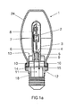
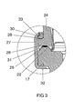
- a ceramic discharge vessel 2 the two-sided is closed, is arranged longitudinally in the lamp axis A. It's tight surrounded by an outer bulb 3, which is squeezed on one side and made of tempered glass or quartz glass is made.
- a frame 4 with short and long supply line 5, 6 holds the discharge vessel 2 in the outer bulb 3.
- the electrodes 7 in the interior of the discharge vessel are connected via bushings 8 with the leads 5, 6.
- the latter are in the region of a pinch 9, which closes the outer bulb 3, connected to external power supply lines 10.
- the pinch 9 of the outer bulb sits over a cavity 11 of a base 12 made of ceramic and is by a Retained holding member 13 made of metal.
- the pedestal can also be from another Be made of material, for example, a heavy-duty plastic.
- the retaining clip 13 protrudes from a plane of the base stone, which is an upper plateau 14 of a radially projecting disk-shaped segment 15 forms.
- the Segment 15 is further provided with a sidewall 16 and a lower plateau 17 executed. It is sitting on a neck part 18, the part assigned to it, here a screw base part 19 threaded, holds.
- the screw base 19 is by means of Crimp 20 attached to the neck portion 18.
- the Power supply lines 10 with electrical connections 21 of the base of the neck portion connected (not visible).
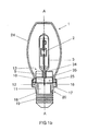
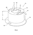
- the holding element 13 is designed in two parts and consists, as shown in detail in the figures 4 and 5, of two joined spring clip elements, namely the main clip 34 and the secondary clip 35 sitting underneath. Both are like a top hat built up. They each have a circumferential brim 36, one at the Inner edge attached side wall 37 and a free end final Lid 38.
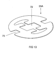
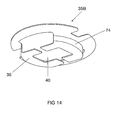
- main clip 34 and slave clip 35 The main difference between main clip 34 and slave clip 35 is the different one Height of the side wall 37. It is in the case of the main clip, in which the Height H of the side wall is typically one to two cm, much larger than in Trap of the secondary clip, in which the height HN of the side wall typically significantly smaller is, and in particular a few mm, about 3 to 6 mm. Under certain circumstances is completely dispensed with the side wall of the side clip. Generally directed the height of the side wall depends on the light center of the in the holding element to be used piston. It may be possible that the Side clip 35A for setting a desired light center no side wall needed, ie a flat disc 71 with corresponding recess 72nd and anti-rotation 73, see Figure 13. At low center of gravity may also require negative values for the height of the sidewall, see Figure 14, i. the side wall 74 extends in the opposite direction, So in the opening 11 of the base stone into it.
- Both elements have a VerFDschutzmechanismus, in the illustrated embodiment in a recess 39, which is roughly rectangular punched in the brim is, is realized. Both elements have this recess the same way twice.
- Both elements see also again Figure 4 and 5, also have an approximately rectangular recess 40 in the lid, the pinch 9 of the outer bulb is adjusted.
- the recess 40 each project four spring tongues 41, the Thus, the I-shaped pinch 9 can fix.
- a part 42 of the side wall, which adjoins the recess can, as shown in Figure 5 for reasons of simplification be distant.
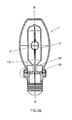
- the enveloping piston 24, see also Fig. 3, is at its opening 25 with a radial projecting edge 27 equipped. He has a flat bottom contact surface 28, which is adapted to the upper plateau 14 of the segment of the base.
- the top Plateau may have bumps 22, which is a spacing of the upper plateau 14 effect to Hüllkolben 24. He also has a narrow upper contact surface 29, which is aligned parallel to the lower contact surface 28 or obliquely thereto. On it sits an elastomeric ring 30, for example made of Viton®.
- Figure 3 shows this area in magnification after a staple part is attached. Shown is a clamp ring made of an aluminum strip 31, the lower edge 32 is angled at about 90 °, so that the band 31 up to the serving as a stop lower plateau 17 of the segment is postponed.
- the stapling effect is achieved in that the upper edge 33, the first aligned straight was subsequently rolled with force, so that he was on the elastomer ring 30 rests.
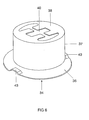
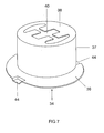
- FIGS. 6 and 7 show another embodiment of a main clip 34. He differs essentially by the differently constructed anti-rotation from the first embodiment. In FIG. 6, it is designed as a bulge 43. In FIG. 7 he designed as a dent 44.
- FIG 8 of the spring clip 13 associated base stone is shown. He fits in with that shown in Figure 7 main clip.
- the base brick 12 has a central opening 11, and a disc-shaped or collar-shaped segment 15 with upper and lower Plateau 14 and 17 and the side wall 16.
- the collar 15 sits on the neck part 18.
- Essential to understanding the anti-rotation is the dent 45, the two opposite sides of the collar is placed in the upper plateau.
- These Delle 45 is similar to the dent 44 in the resilient clip elements, both at main clip 34 and side clip 35. This allows the joined clip elements 34, 35 are also joined to the base brick 12 by each of all three components with aligned dents 44, 45 are arranged.
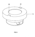
- Fig. 9 shows another embodiment of the base block 12, in which the anti-rotation part a bulge 46 is.
- This bump 46 is either shaped like the same the bulge 43 of the main clip in Figure 6, so that here again a twist is realized, the quasi the positive to the solution shown in Figure 8 means Represents negative.
- the bulge 46 with the correspondingly adapted recesses 39 can interact from Figure 4 and 5.
- the solution has the bumps the advantage that this easily a permanent connection of the resilient Clip elements is possible by main and secondary clip 34, 35, for example connected by laser welding in the region of the two bumps 39 become.
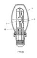
- FIG. 10 shows a reflector lamp 60 with a reflector part 61 as an enveloping part.
- the contour of the reflector part 61 is made of aluminum.
- On the base stone 62 sits a separate collar ring 63 which is cylindrically shaped and the outer bulb 64 partially surrounds, but below the discharge volume 65 of Discharge vessel 66 ends.
- An attachment is realized by crimping. For details, this can be found in DE-Az 103 36 282.7.
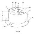
- Fig. 11 shows a holding device, which consists of only one element.
- the spring clip element 48 has the same structure as the main clip in Figure 4.
- the two other spring tongues 50 are in front of the Inserting the piston is still straight, but may already be in advance for support be bent down a bit. It is recommended for better axial alignment as similar pairs of spring tongues always diametrically opposed Use spring tongues.
- Main and secondary clip also united in a single spring clip 34A.
- the clip executed in principle as a main clip, with lid 38 as the first holding plane.
- the second holding plane, which is normally formed by the lid of the secondary clip is is now through from the cylindrical portion of the clip, so the side wall 37, punched and spring-bent elements 69 replaced.
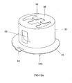
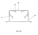
- FIG. 12b is constructed in a manner very similar to FIG. 12a. but it shows a clip 80, in which the resilient elements in contrast to Figure 12a elements 81 of the side wall 83 are again at their free ends are bent over. the spring tongues 82 on the cover are already slightly bent downwards.
- the dimensions of the Clip element suitably matched to each other, especially the diameter
- the cylindrical side walls should be slightly different. It is advisable in particular a slightly conical shape of the side walls, the stackability favored several clip elements.
Applications Claiming Priority (2)
| Application Number | Priority Date | Filing Date | Title |
|---|---|---|---|
| DE10358361A DE10358361A1 (de) | 2003-12-12 | 2003-12-12 | Haltevorrichtung zur Fixierung eines Lampenkolbens und zugehörige Lampe |
| DE10358361 | 2003-12-12 |
Publications (3)
| Publication Number | Publication Date |
|---|---|
| EP1542256A2 true EP1542256A2 (fr) | 2005-06-15 |
| EP1542256A3 EP1542256A3 (fr) | 2010-02-17 |
| EP1542256B1 EP1542256B1 (fr) | 2013-02-13 |
Family
ID=34485356
Family Applications (1)
| Application Number | Title | Priority Date | Filing Date |
|---|---|---|---|
| EP04028444A Not-in-force EP1542256B1 (fr) | 2003-12-12 | 2004-12-01 | Dispositif de fixation pour une ampoule de lampe et lampe pourvue d'un tel dispositif |
Country Status (6)
| Country | Link |
|---|---|
| US (1) | US7550908B2 (fr) |
| EP (1) | EP1542256B1 (fr) |
| JP (1) | JP4772319B2 (fr) |
| CN (1) | CN100449884C (fr) |
| CA (1) | CA2489750A1 (fr) |
| DE (1) | DE10358361A1 (fr) |
Cited By (3)
| Publication number | Priority date | Publication date | Assignee | Title |
|---|---|---|---|---|
| WO2007099124A1 (fr) * | 2006-03-02 | 2007-09-07 | Osram Gesellschaft mit beschränkter Haftung | Lampe munie d'une lampe encastrée |
| EP2339609A1 (fr) * | 2009-12-22 | 2011-06-29 | Osram Gesellschaft mit Beschränkter Haftung | Lampe à décharge haute tension |
| EP2020676A3 (fr) * | 2007-07-30 | 2012-04-11 | Osram Gesellschaft mit beschränkter Haftung | Lampe électrique dotée d'une enveloppe extérieure et d'une lampe intégrée et son procédé de fabrication |
Families Citing this family (19)
| Publication number | Priority date | Publication date | Assignee | Title |
|---|---|---|---|---|
| DE102005005264A1 (de) * | 2005-02-04 | 2006-08-10 | Patent-Treuhand-Gesellschaft für elektrische Glühlampen mbH | Einseitig gesockelte Lampe |
| JP4130829B2 (ja) * | 2005-08-23 | 2008-08-06 | 松下電器産業株式会社 | 金属蒸気放電ランプ、および当該金属蒸気放電ランプを有する照明装置 |
| JP4547331B2 (ja) * | 2005-12-28 | 2010-09-22 | パナソニック株式会社 | 照明装置及び金属蒸気放電ランプ |
| JP4682048B2 (ja) * | 2006-02-01 | 2011-05-11 | パナソニック株式会社 | 金属蒸気放電ランプ |
| WO2007139095A1 (fr) * | 2006-05-31 | 2007-12-06 | Panasonic Corporation | Lampe à décharge à vapeur métallique et dispostif d'éclairage |
| JP4130842B2 (ja) * | 2006-05-31 | 2008-08-06 | 松下電器産業株式会社 | 金属蒸気放電ランプ及び照明装置 |
| JP2008210699A (ja) * | 2007-02-27 | 2008-09-11 | Osram Melco Toshiba Lighting Kk | 高圧放電ランプおよび照明器具 |
| CN101641759B (zh) | 2007-03-12 | 2013-05-22 | 皇家飞利浦电子股份有限公司 | 高压放电灯 |
| DE102007053564A1 (de) * | 2007-11-09 | 2009-05-14 | Osram Gesellschaft mit beschränkter Haftung | Elektrische Lampe mit einem Außenkolben und einer Einbaulampe |
| JP5372021B2 (ja) * | 2008-02-29 | 2013-12-18 | コーニンクレッカ フィリップス エヌ ヴェ | 電球口金及び電球口金を製造する方法 |
| DE202008007575U1 (de) * | 2008-06-06 | 2008-08-21 | Osram Gesellschaft mit beschränkter Haftung | Einseitig gesockelte Lampe |
| JP2010056031A (ja) * | 2008-08-29 | 2010-03-11 | Osram Melco Toshiba Lighting Kk | 高圧放電ランプおよび照明装置 |
| GB2477994A (en) | 2010-02-23 | 2011-08-24 | Ecolumens Ltd | Liquid cooled semiconductor light |
| JP2011238398A (ja) * | 2010-05-07 | 2011-11-24 | Osram Melco Toshiba Lighting Kk | 管球および照明装置 |
| JP4872008B2 (ja) * | 2010-05-07 | 2012-02-08 | パナソニック株式会社 | 照明装置及び金属蒸気放電ランプ |
| RU2444814C1 (ru) * | 2011-03-29 | 2012-03-10 | Юрий Феликсович Верниковский | Термоэлектрический кластер, способ его работы, устройство соединения в нем активного элемента с теплоэлектропроводом, генератор (варианты) и тепловой насос (варианты) на его основе |
| WO2013168044A1 (fr) * | 2012-05-07 | 2013-11-14 | Koninklijke Philips N.V. | Lampe électrique et procédé de montage associé |
| US11028989B2 (en) | 2019-11-13 | 2021-06-08 | James M. Aparo | Vehicle headlight device having an ejectable and replaceable lightbulb assembly |
| US11046235B2 (en) | 2019-11-13 | 2021-06-29 | James M. Aparo | Vehicle headlight assembly having an ejectable and replaceable lightbulb |
Citations (3)
| Publication number | Priority date | Publication date | Assignee | Title |
|---|---|---|---|---|
| DE3837511A1 (de) * | 1988-11-04 | 1990-05-10 | Philips Patentverwaltung | Kraftfahrzeugscheinwerferlampe und verfahren zu ihrer herstellung |
| DE4434124A1 (de) * | 1994-09-23 | 1996-03-28 | Walter Holzer | Reflektor für Leuchtstofflampen |
| DE10210856A1 (de) * | 2001-07-06 | 2003-01-16 | Philips Corp Intellectual Pty | Lampe, insbesondere für Kfz-Scheinwerfer |
Family Cites Families (22)
| Publication number | Priority date | Publication date | Assignee | Title |
|---|---|---|---|---|
| JPS59136150A (ja) * | 1983-01-27 | 1984-08-04 | Dowa Mining Co Ltd | 金属塩殿物と石膏の浮選分離法 |
| US4623958A (en) * | 1985-01-15 | 1986-11-18 | Gte Products Corporation | Replaceable automobile headlight lamp unit |
| US5172026A (en) * | 1990-05-21 | 1992-12-15 | Hall Rolland B | Plug in lamp |
| US5465025A (en) * | 1993-05-10 | 1995-11-07 | Litetronics International, Inc. | Lamp with removable base and replaceable bulb capsule |
| DE4317252C1 (de) | 1993-05-24 | 1994-05-05 | Blv Licht & Vakuumtechnik | Gasentladungslampe |
| JPH07320522A (ja) * | 1994-05-24 | 1995-12-08 | Yuhshin Co Ltd | 電球支持装置 |
| US5818154A (en) * | 1994-08-10 | 1998-10-06 | Patent-Treuhand-Gesellschaft Fur Elektrische Gluhlampen Mbh | Halogen incandescent lamp in cementless base |
| DE4428357A1 (de) * | 1994-08-10 | 1996-02-15 | Patent Treuhand Ges Fuer Elektrische Gluehlampen Mbh | Kittlos gesockelte Halogenglühlampe |
| US5711596A (en) * | 1995-08-28 | 1998-01-27 | Osram Sylvania Inc. | Mechanical electrical connector for an electric lamp |
| CN1118841C (zh) * | 1996-09-11 | 2003-08-20 | 皇家菲利浦电子有限公司 | 反光灯 |
| DE19709928A1 (de) * | 1997-03-11 | 1998-09-17 | Patent Treuhand Ges Fuer Elektrische Gluehlampen Mbh | Halogenglühlampe und Fassung |
| JPH11260319A (ja) * | 1998-03-09 | 1999-09-24 | Ichikoh Ind Ltd | キャップ付きバルブ |
| DE59912232D1 (de) | 1998-05-22 | 2005-08-11 | Phoenix Contact Gmbh & Co | Elektrische Anschlussbaueinheit |
| DE19843506A1 (de) * | 1998-09-23 | 2000-03-30 | Patent Treuhand Ges Fuer Elektrische Gluehlampen Mbh | Elektrische Lampe |
| DE19856871A1 (de) * | 1998-12-09 | 2000-06-15 | Patent Treuhand Ges Fuer Elektrische Gluehlampen Mbh | Kittlos gesockelte Lampe |
| DE19951203A1 (de) * | 1999-10-22 | 2001-04-26 | Patent Treuhand Ges Fuer Elektrische Gluehlampen Mbh | Schweinwerferlampe |
| WO2003005399A1 (fr) * | 2001-07-06 | 2003-01-16 | Koninklijke Philips Electronics N.V. | Lampe utilisee notamment dans les phares avant des automobiles |
| DE10260125A1 (de) * | 2002-12-19 | 2004-07-01 | Patent-Treuhand-Gesellschaft für elektrische Glühlampen mbH | Beleuchtungseinheit |
| US7002285B2 (en) * | 2003-01-03 | 2006-02-21 | General Electric Company | Discharge lamp with bulb fixture arrangement and method for manufacturing the same |
| DE10312806A1 (de) * | 2003-03-21 | 2004-09-30 | Patent-Treuhand-Gesellschaft für elektrische Glühlampen mbH | Lampe |
| DE10336282A1 (de) | 2003-08-07 | 2005-02-17 | Patent-Treuhand-Gesellschaft für elektrische Glühlampen mbH | Einseitig gesockelte Lampe |
| TWI363365B (en) * | 2003-10-03 | 2012-05-01 | Koninkl Philips Electronics Nv | Discharge lamp |
-
2003
- 2003-12-12 DE DE10358361A patent/DE10358361A1/de not_active Withdrawn
-
2004
- 2004-12-01 EP EP04028444A patent/EP1542256B1/fr not_active Not-in-force
- 2004-12-09 JP JP2004357044A patent/JP4772319B2/ja not_active Expired - Fee Related
- 2004-12-10 CA CA002489750A patent/CA2489750A1/fr not_active Abandoned
- 2004-12-13 CN CNB2004100758913A patent/CN100449884C/zh not_active Expired - Fee Related
- 2004-12-13 US US11/009,032 patent/US7550908B2/en not_active Expired - Fee Related
Patent Citations (3)
| Publication number | Priority date | Publication date | Assignee | Title |
|---|---|---|---|---|
| DE3837511A1 (de) * | 1988-11-04 | 1990-05-10 | Philips Patentverwaltung | Kraftfahrzeugscheinwerferlampe und verfahren zu ihrer herstellung |
| DE4434124A1 (de) * | 1994-09-23 | 1996-03-28 | Walter Holzer | Reflektor für Leuchtstofflampen |
| DE10210856A1 (de) * | 2001-07-06 | 2003-01-16 | Philips Corp Intellectual Pty | Lampe, insbesondere für Kfz-Scheinwerfer |
Cited By (4)
| Publication number | Priority date | Publication date | Assignee | Title |
|---|---|---|---|---|
| WO2007099124A1 (fr) * | 2006-03-02 | 2007-09-07 | Osram Gesellschaft mit beschränkter Haftung | Lampe munie d'une lampe encastrée |
| US8079741B2 (en) | 2006-03-02 | 2011-12-20 | Osram Ag | Lamp with a built-in lamp |
| EP2020676A3 (fr) * | 2007-07-30 | 2012-04-11 | Osram Gesellschaft mit beschränkter Haftung | Lampe électrique dotée d'une enveloppe extérieure et d'une lampe intégrée et son procédé de fabrication |
| EP2339609A1 (fr) * | 2009-12-22 | 2011-06-29 | Osram Gesellschaft mit Beschränkter Haftung | Lampe à décharge haute tension |
Also Published As
| Publication number | Publication date |
|---|---|
| CN100449884C (zh) | 2009-01-07 |
| US7550908B2 (en) | 2009-06-23 |
| EP1542256B1 (fr) | 2013-02-13 |
| CA2489750A1 (fr) | 2005-06-12 |
| DE10358361A1 (de) | 2005-07-07 |
| JP2005174936A (ja) | 2005-06-30 |
| EP1542256A3 (fr) | 2010-02-17 |
| US20050127807A1 (en) | 2005-06-16 |
| JP4772319B2 (ja) | 2011-09-14 |
| CN1655410A (zh) | 2005-08-17 |
Similar Documents
| Publication | Publication Date | Title |
|---|---|---|
| EP1542256B1 (fr) | Dispositif de fixation pour une ampoule de lampe et lampe pourvue d'un tel dispositif | |
| DE10336282A1 (de) | Einseitig gesockelte Lampe | |
| EP1222675B1 (fr) | Lampe de phare | |
| EP0839381B1 (fr) | Lampe a reflecteur | |
| DE60021218T2 (de) | Bogenröhre, Montageelement und elektrische Lampenanordnung | |
| DE19856871A1 (de) | Kittlos gesockelte Lampe | |
| DE3616330A1 (de) | Kurzbogenlampe | |
| WO2006081806A2 (fr) | Lampe a culot unilateral | |
| WO2010124904A1 (fr) | Lampe à décharge | |
| WO2009156251A2 (fr) | Lampe électrique comprenant une ampoule extérieure et une lampe encastrée | |
| EP2131382B1 (fr) | Lampe à culot unique | |
| DE19722601A1 (de) | Halterungsfeder und Anschlagvorrichtung für Lampenbefestigung | |
| EP0401637A2 (fr) | Lampe électrique | |
| EP2510537B1 (fr) | Lampe à incandescence halogène pour phare de véhicule | |
| DE202004012293U1 (de) | Einseitig gesockelte Lampe | |
| EP2009668B1 (fr) | Lampe à décharge avec culot unique | |
| EP1329931B1 (fr) | Lampe compacte à décharge à basse pression | |
| DE19918980A1 (de) | Verschlußteil für eine Lampe mit verbesserten Stoß- und Schwingungseigenschaften | |
| WO2009049661A1 (fr) | Lampe à décharge haute pression | |
| EP2458614B1 (fr) | Lampe électrique comprenant une ampoule extérieure et une lampe intégrée | |
| EP3279920A1 (fr) | Élement de centrage et support d'ampoule | |
| EP2399268A1 (fr) | Lampe électrique comportant un piston extérieur et une lampe intégrée | |
| DE102004056004A1 (de) | Hochdruckentladungslampe | |
| EP2084727B1 (fr) | Source électrique de lumière destinée en particulier pour utilisation dans un réflecteur | |
| DE99413C (fr) |
Legal Events
| Date | Code | Title | Description |
|---|---|---|---|
| PUAI | Public reference made under article 153(3) epc to a published international application that has entered the european phase |
Free format text: ORIGINAL CODE: 0009012 |
|
| AK | Designated contracting states |
Kind code of ref document: A2 Designated state(s): AT BE BG CH CY CZ DE DK EE ES FI FR GB GR HU IE IS IT LI LT LU MC NL PL PT RO SE SI SK TR |
|
| AX | Request for extension of the european patent |
Extension state: AL BA HR LV MK YU |
|
| PUAL | Search report despatched |
Free format text: ORIGINAL CODE: 0009013 |
|
| AK | Designated contracting states |
Kind code of ref document: A3 Designated state(s): AT BE BG CH CY CZ DE DK EE ES FI FR GB GR HU IE IS IT LI LT LU MC NL PL PT RO SE SI SK TR |
|
| AX | Request for extension of the european patent |
Extension state: AL BA HR LV MK YU |
|
| 17P | Request for examination filed |
Effective date: 20100521 |
|
| 17Q | First examination report despatched |
Effective date: 20100615 |
|
| AKX | Designation fees paid |
Designated state(s): AT BE BG CH CY CZ DE DK EE ES FI FR GB GR HU IE IS IT LI LT LU MC NL PL PT RO SE SI SK TR |
|
| RAP1 | Party data changed (applicant data changed or rights of an application transferred) |
Owner name: OSRAM GESELLSCHAFT MIT BESCHRAENKTER HAFTUNG |
|
| GRAP | Despatch of communication of intention to grant a patent |
Free format text: ORIGINAL CODE: EPIDOSNIGR1 |
|
| RAP1 | Party data changed (applicant data changed or rights of an application transferred) |
Owner name: OSRAM AG |
|
| GRAS | Grant fee paid |
Free format text: ORIGINAL CODE: EPIDOSNIGR3 |
|
| GRAA | (expected) grant |
Free format text: ORIGINAL CODE: 0009210 |
|
| AK | Designated contracting states |
Kind code of ref document: B1 Designated state(s): AT BE BG CH CY CZ DE DK EE ES FI FR GB GR HU IE IS IT LI LT LU MC NL PL PT RO SE SI SK TR |
|
| REG | Reference to a national code |
Ref country code: GB Ref legal event code: FG4D Free format text: NOT ENGLISH |
|
| REG | Reference to a national code |
Ref country code: AT Ref legal event code: REF Ref document number: 596874 Country of ref document: AT Kind code of ref document: T Effective date: 20130215 |
|
| RAP2 | Party data changed (patent owner data changed or rights of a patent transferred) |
Owner name: OSRAM GMBH |
|
| REG | Reference to a national code |
Ref country code: IE Ref legal event code: FG4D Free format text: LANGUAGE OF EP DOCUMENT: GERMAN |
|
| REG | Reference to a national code |
Ref country code: DE Ref legal event code: R096 Ref document number: 502004014016 Country of ref document: DE Effective date: 20130411 |
|
| REG | Reference to a national code |
Ref country code: AT Ref legal event code: HC Ref document number: 596874 Country of ref document: AT Kind code of ref document: T Owner name: OSRAM GMBH, DE Effective date: 20130221 |
|
| RAP2 | Party data changed (patent owner data changed or rights of a patent transferred) |
Owner name: OSRAM GMBH |
|
| REG | Reference to a national code |
Ref country code: NL Ref legal event code: VDEP Effective date: 20130213 |
|
| REG | Reference to a national code |
Ref country code: LT Ref legal event code: MG4D Effective date: 20121209 |
|
| PG25 | Lapsed in a contracting state [announced via postgrant information from national office to epo] |
Ref country code: LT Free format text: LAPSE BECAUSE OF FAILURE TO SUBMIT A TRANSLATION OF THE DESCRIPTION OR TO PAY THE FEE WITHIN THE PRESCRIBED TIME-LIMIT Effective date: 20130213 Ref country code: IS Free format text: LAPSE BECAUSE OF FAILURE TO SUBMIT A TRANSLATION OF THE DESCRIPTION OR TO PAY THE FEE WITHIN THE PRESCRIBED TIME-LIMIT Effective date: 20130613 Ref country code: BG Free format text: LAPSE BECAUSE OF FAILURE TO SUBMIT A TRANSLATION OF THE DESCRIPTION OR TO PAY THE FEE WITHIN THE PRESCRIBED TIME-LIMIT Effective date: 20130513 Ref country code: ES Free format text: LAPSE BECAUSE OF FAILURE TO SUBMIT A TRANSLATION OF THE DESCRIPTION OR TO PAY THE FEE WITHIN THE PRESCRIBED TIME-LIMIT Effective date: 20130524 Ref country code: CY Free format text: LAPSE BECAUSE OF FAILURE TO SUBMIT A TRANSLATION OF THE DESCRIPTION OR TO PAY THE FEE WITHIN THE PRESCRIBED TIME-LIMIT Effective date: 20130213 Ref country code: SE Free format text: LAPSE BECAUSE OF FAILURE TO SUBMIT A TRANSLATION OF THE DESCRIPTION OR TO PAY THE FEE WITHIN THE PRESCRIBED TIME-LIMIT Effective date: 20130213 |
|
| PG25 | Lapsed in a contracting state [announced via postgrant information from national office to epo] |
Ref country code: SI Free format text: LAPSE BECAUSE OF FAILURE TO SUBMIT A TRANSLATION OF THE DESCRIPTION OR TO PAY THE FEE WITHIN THE PRESCRIBED TIME-LIMIT Effective date: 20130213 Ref country code: PL Free format text: LAPSE BECAUSE OF FAILURE TO SUBMIT A TRANSLATION OF THE DESCRIPTION OR TO PAY THE FEE WITHIN THE PRESCRIBED TIME-LIMIT Effective date: 20130213 Ref country code: PT Free format text: LAPSE BECAUSE OF FAILURE TO SUBMIT A TRANSLATION OF THE DESCRIPTION OR TO PAY THE FEE WITHIN THE PRESCRIBED TIME-LIMIT Effective date: 20130613 Ref country code: FI Free format text: LAPSE BECAUSE OF FAILURE TO SUBMIT A TRANSLATION OF THE DESCRIPTION OR TO PAY THE FEE WITHIN THE PRESCRIBED TIME-LIMIT Effective date: 20130213 Ref country code: GR Free format text: LAPSE BECAUSE OF FAILURE TO SUBMIT A TRANSLATION OF THE DESCRIPTION OR TO PAY THE FEE WITHIN THE PRESCRIBED TIME-LIMIT Effective date: 20130514 |
|
| PG25 | Lapsed in a contracting state [announced via postgrant information from national office to epo] |
Ref country code: SK Free format text: LAPSE BECAUSE OF FAILURE TO SUBMIT A TRANSLATION OF THE DESCRIPTION OR TO PAY THE FEE WITHIN THE PRESCRIBED TIME-LIMIT Effective date: 20130213 Ref country code: CZ Free format text: LAPSE BECAUSE OF FAILURE TO SUBMIT A TRANSLATION OF THE DESCRIPTION OR TO PAY THE FEE WITHIN THE PRESCRIBED TIME-LIMIT Effective date: 20130213 Ref country code: EE Free format text: LAPSE BECAUSE OF FAILURE TO SUBMIT A TRANSLATION OF THE DESCRIPTION OR TO PAY THE FEE WITHIN THE PRESCRIBED TIME-LIMIT Effective date: 20130213 Ref country code: NL Free format text: LAPSE BECAUSE OF FAILURE TO SUBMIT A TRANSLATION OF THE DESCRIPTION OR TO PAY THE FEE WITHIN THE PRESCRIBED TIME-LIMIT Effective date: 20130213 Ref country code: RO Free format text: LAPSE BECAUSE OF FAILURE TO SUBMIT A TRANSLATION OF THE DESCRIPTION OR TO PAY THE FEE WITHIN THE PRESCRIBED TIME-LIMIT Effective date: 20130213 Ref country code: DK Free format text: LAPSE BECAUSE OF FAILURE TO SUBMIT A TRANSLATION OF THE DESCRIPTION OR TO PAY THE FEE WITHIN THE PRESCRIBED TIME-LIMIT Effective date: 20130213 |
|
| REG | Reference to a national code |
Ref country code: DE Ref legal event code: R081 Ref document number: 502004014016 Country of ref document: DE Owner name: OSRAM GMBH, DE Free format text: FORMER OWNER: OSRAM GMBH, 81543 MUENCHEN, DE Effective date: 20130909 Ref country code: DE Ref legal event code: R081 Ref document number: 502004014016 Country of ref document: DE Owner name: OSRAM GMBH, DE Free format text: FORMER OWNER: PATENT-TREUHAND-GESELLSCHAFT FUER ELEKTRISCHE GLUEHLAMPEN MBH, 81543 MUENCHEN, DE Effective date: 20130213 |
|
| PLBE | No opposition filed within time limit |
Free format text: ORIGINAL CODE: 0009261 |
|
| STAA | Information on the status of an ep patent application or granted ep patent |
Free format text: STATUS: NO OPPOSITION FILED WITHIN TIME LIMIT |
|
| PG25 | Lapsed in a contracting state [announced via postgrant information from national office to epo] |
Ref country code: IT Free format text: LAPSE BECAUSE OF FAILURE TO SUBMIT A TRANSLATION OF THE DESCRIPTION OR TO PAY THE FEE WITHIN THE PRESCRIBED TIME-LIMIT Effective date: 20130213 |
|
| 26N | No opposition filed |
Effective date: 20131114 |
|
| REG | Reference to a national code |
Ref country code: DE Ref legal event code: R097 Ref document number: 502004014016 Country of ref document: DE Effective date: 20131114 |
|
| BERE | Be: lapsed |
Owner name: OSRAM A.G. Effective date: 20131231 |
|
| REG | Reference to a national code |
Ref country code: DE Ref legal event code: R119 Ref document number: 502004014016 Country of ref document: DE |
|
| REG | Reference to a national code |
Ref country code: CH Ref legal event code: PL |
|
| GBPC | Gb: european patent ceased through non-payment of renewal fee |
Effective date: 20131201 |
|
| PG25 | Lapsed in a contracting state [announced via postgrant information from national office to epo] |
Ref country code: MC Free format text: LAPSE BECAUSE OF FAILURE TO SUBMIT A TRANSLATION OF THE DESCRIPTION OR TO PAY THE FEE WITHIN THE PRESCRIBED TIME-LIMIT Effective date: 20130213 Ref country code: LU Free format text: LAPSE BECAUSE OF FAILURE TO SUBMIT A TRANSLATION OF THE DESCRIPTION OR TO PAY THE FEE WITHIN THE PRESCRIBED TIME-LIMIT Effective date: 20131201 |
|
| REG | Reference to a national code |
Ref country code: IE Ref legal event code: MM4A |
|
| REG | Reference to a national code |
Ref country code: DE Ref legal event code: R119 Ref document number: 502004014016 Country of ref document: DE Effective date: 20140701 |
|
| REG | Reference to a national code |
Ref country code: FR Ref legal event code: ST Effective date: 20140829 |
|
| PG25 | Lapsed in a contracting state [announced via postgrant information from national office to epo] |
Ref country code: LI Free format text: LAPSE BECAUSE OF NON-PAYMENT OF DUE FEES Effective date: 20131231 Ref country code: CH Free format text: LAPSE BECAUSE OF NON-PAYMENT OF DUE FEES Effective date: 20131231 Ref country code: DE Free format text: LAPSE BECAUSE OF NON-PAYMENT OF DUE FEES Effective date: 20140701 Ref country code: BE Free format text: LAPSE BECAUSE OF NON-PAYMENT OF DUE FEES Effective date: 20131231 Ref country code: IE Free format text: LAPSE BECAUSE OF NON-PAYMENT OF DUE FEES Effective date: 20131201 |
|
| PG25 | Lapsed in a contracting state [announced via postgrant information from national office to epo] |
Ref country code: FR Free format text: LAPSE BECAUSE OF NON-PAYMENT OF DUE FEES Effective date: 20131231 Ref country code: GB Free format text: LAPSE BECAUSE OF NON-PAYMENT OF DUE FEES Effective date: 20131201 |
|
| REG | Reference to a national code |
Ref country code: AT Ref legal event code: MM01 Ref document number: 596874 Country of ref document: AT Kind code of ref document: T Effective date: 20131201 |
|
| PG25 | Lapsed in a contracting state [announced via postgrant information from national office to epo] |
Ref country code: AT Free format text: LAPSE BECAUSE OF NON-PAYMENT OF DUE FEES Effective date: 20131201 |
|
| PG25 | Lapsed in a contracting state [announced via postgrant information from national office to epo] |
Ref country code: TR Free format text: LAPSE BECAUSE OF FAILURE TO SUBMIT A TRANSLATION OF THE DESCRIPTION OR TO PAY THE FEE WITHIN THE PRESCRIBED TIME-LIMIT Effective date: 20130213 |
|
| PG25 | Lapsed in a contracting state [announced via postgrant information from national office to epo] |
Ref country code: HU Free format text: LAPSE BECAUSE OF FAILURE TO SUBMIT A TRANSLATION OF THE DESCRIPTION OR TO PAY THE FEE WITHIN THE PRESCRIBED TIME-LIMIT; INVALID AB INITIO Effective date: 20041201 |