EP2339609A1 - Lampe à décharge haute tension - Google Patents
Lampe à décharge haute tension Download PDFInfo
- Publication number
- EP2339609A1 EP2339609A1 EP10191245A EP10191245A EP2339609A1 EP 2339609 A1 EP2339609 A1 EP 2339609A1 EP 10191245 A EP10191245 A EP 10191245A EP 10191245 A EP10191245 A EP 10191245A EP 2339609 A1 EP2339609 A1 EP 2339609A1
- Authority
- EP
- European Patent Office
- Prior art keywords
- outer bulb
- discharge lamp
- pressure discharge
- base
- lamp according
- Prior art date
- Legal status (The legal status is an assumption and is not a legal conclusion. Google has not performed a legal analysis and makes no representation as to the accuracy of the status listed.)
- Withdrawn
Links
Images
Classifications
-
- H—ELECTRICITY
- H01—ELECTRIC ELEMENTS
- H01J—ELECTRIC DISCHARGE TUBES OR DISCHARGE LAMPS
- H01J61/00—Gas-discharge or vapour-discharge lamps
- H01J61/02—Details
- H01J61/30—Vessels; Containers
- H01J61/34—Double-wall vessels or containers
-
- H—ELECTRICITY
- H01—ELECTRIC ELEMENTS
- H01J—ELECTRIC DISCHARGE TUBES OR DISCHARGE LAMPS
- H01J5/00—Details relating to vessels or to leading-in conductors common to two or more basic types of discharge tubes or lamps
- H01J5/50—Means forming part of the tube or lamps for the purpose of providing electrical connection to it
- H01J5/54—Means forming part of the tube or lamps for the purpose of providing electrical connection to it supported by a separate part, e.g. base
-
- H—ELECTRICITY
- H01—ELECTRIC ELEMENTS
- H01J—ELECTRIC DISCHARGE TUBES OR DISCHARGE LAMPS
- H01J61/00—Gas-discharge or vapour-discharge lamps
- H01J61/02—Details
- H01J61/30—Vessels; Containers
- H01J61/302—Vessels; Containers characterised by the material of the vessel
Definitions
- the invention relates to a high-pressure discharge lamp according to the preamble of claim 1.
- Such lamps are in particular high-pressure discharge lamps for general lighting or for photo-optical purposes.
- the object of the present invention is to provide a high-pressure discharge lamp according to the preamble of claim 1, which is compact and yet has sufficient Platzertik.
- the invention relates to space-protected lamps with two outer pistons in the entire power range.
- the second outer bulb is a sheath, which serves as Platzertik for possible lamp destruction in case of negative influences.
- the fixing of the outer bulb must be done so that the destruction of the lamp or other negative influences do not damage the outer bulb.
- the outer bulb must also be protected against rotation to the base to ensure trouble-free switching on and off of the lamp.
- the invention particularly relates to space-protected lamps with outer bulb and a sheath in the low-wattage power range to a maximum of 150 W.
- the sheath serves as Platzerschutz for possible lamp destruction by negative influences.
- the sheathing is in particular made of glass or plastic, in any case, it must be suitable for high temperatures and photometrically suitable.
- the second outer bulb preferably made of hard glass, is fixed by deformation after a corresponding heating process in the pinch region of the base lamp, preferably with outer bulb made of quartz glass.
- the two normally different glasses of the two outer pistons must not fuse (different coefficient of expansion).
- a spring in the dome area provides the necessary bias of the base lamp in the outer bulb to avoid rattling or wobbling of the second outer bulb.
- the attachment of the second outer bulb is relieved differently.
- the second outer bulb is provided with side holes or holes at the level of the base.
- the base has at these positions holes or recesses for receiving a pin-shaped fastening means, such as a split pin, rivet, pin, screw or the like.
- the outer bulb is thus fixed by means of a split pin, rivet, pin, a screw or the like, which are driven from the outside through the hole / hole in the socket.
- the attachment meets the requirements for the maintenance of the outer bulb on the base, as well as the anti-rotation.
- a bias of the second outer piston achieved in that takes place before the pinning of the system, a compression of the spring washer by compressive force.
- the fixation of the second outer piston takes place by the pressing of at least one pin or the like, preferably of two opposite pins or the like.
- the compression spring or spring washer also known as a plate spring as known per se, is intended to prevent tilting and shaking of the second outer bulb on the support plateau.
- the pins can be made of metal or plastic. This process is very time-saving and needs no additional process effort, such as kiting, melting or rolling.
- the second outer bulb can in principle also be made of plastic, provided that it is sufficiently heat-resistant.
- a suitable plastic for such a jacket is particularly, at least proportionally, polycarbonate, polyester, poly-methyl methacrylate or polyolefin.
- transparent, UV-stable, high-temperature-stable plastics, in particular Teflon, PTFE are particularly suitable.
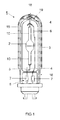
- FIG. 1 shows the structure of a high pressure discharge lamp 1 highly schematic. It has as base lamp a discharge vessel 2, which is housed in an outer bulb 3. The outer leads 4 of the discharge vessel, the Contact electrodes inside are connected to two frame wires 5 and 6. A short frame wire 5 leads to a first foil 7 in a pinch 8 of the outer bulb. A long frame wire 6, often called stirrup wire, leads to a second film 7 in the pinch 8.
- the discharge vessel 2 has at its ends in each case a capillary 10, as known per se, and a filling of an ionizable gas, usually argon or Xenon, mercury and metal halides, also known per se. Two electrodes are located in the interior of the discharge vessel, as also known per se, and not shown here.
- the outer bulb 3 is surrounded by a second outer bulb or casing 15 made of hard glass, which bears tightly against the Au ⁇ enkolben 3.
- This second outer bulb 15 is made of tempered glass, while the inner outer bulb 3 is made of quartz glass.
- the attachment of the second outer piston 15 takes place directly on the first outer bulb 3 approximately at the level of the pinch seal 8 by a "gentle" pinch 16. This is meant a positive fit of the outer bulb, initially leaving a small clear distance.
- the outer bulb 3 of the base lamp in the dome 18 of the second outer bulb by a conically downwardly widening spring 19 or similar. centered, as is known. A final fixation of the outer bulb takes place by the spring force of the spring 19th
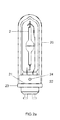
- FIG. 2 shows an embodiment that takes into account the high temperature load in an improved manner. It is in the side view of FIG. 2a the second outer piston 20 with a socket-side cylindrical Opening 21 provided.
- the second outer bulb 20 is placed on a stop 22, which projects laterally on the base 23. He is attached there by means of a splint 24, see FIG. 2b ,
- the second outer bulb has a hole 25 through which the split pin 24 is inserted into a recess 26 of the base.
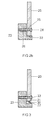
- FIG. 3 is similar in construction FIG. 2 , However, here in the region of the stop 22, an annular plate spring 30 on the base edge, which serves as a stop 22, placed on which in turn rests the opening 21 of the second outer bulb.
- the spring force of the plate spring 30 allows a pressing of the second outer piston 20 on the stop 22 of the base, wherein the second outer bulb is fixed in the pressed state by means of two mold pins 33.
- glass for the second outer bulb 20 are all possible glasses, such as soft glass or quartz glass, in particular, is suitable as hard glass borosilicate glass, etc.
- the discharge vessel 2 need not be made of ceramic, it can also be made of quartz glass or similar. be made.
- a high-pressure discharge lamp has a ceramic discharge vessel which is accommodated in an outer bulb, wherein the outer bulb is also surrounded by a second outer bulb as splinter protection, which bears tightly against the outer bulb.
- the outer bulb is socketed on one side and the discharge vessel is equipped with two ends.
Landscapes
- Vessels And Coating Films For Discharge Lamps (AREA)
- Common Detailed Techniques For Electron Tubes Or Discharge Tubes (AREA)
- Non-Portable Lighting Devices Or Systems Thereof (AREA)
Applications Claiming Priority (1)
| Application Number | Priority Date | Filing Date | Title |
|---|---|---|---|
| DE102009055171A DE102009055171A1 (de) | 2009-12-22 | 2009-12-22 | Hochdruckentladungslampe |
Publications (1)
| Publication Number | Publication Date |
|---|---|
| EP2339609A1 true EP2339609A1 (fr) | 2011-06-29 |
Family
ID=43379043
Family Applications (1)
| Application Number | Title | Priority Date | Filing Date |
|---|---|---|---|
| EP10191245A Withdrawn EP2339609A1 (fr) | 2009-12-22 | 2010-11-15 | Lampe à décharge haute tension |
Country Status (5)
| Country | Link |
|---|---|
| US (1) | US20110148296A1 (fr) |
| EP (1) | EP2339609A1 (fr) |
| JP (1) | JP2011134711A (fr) |
| CN (1) | CN102103976A (fr) |
| DE (1) | DE102009055171A1 (fr) |
Families Citing this family (1)
| Publication number | Priority date | Publication date | Assignee | Title |
|---|---|---|---|---|
| CN102842473B (zh) * | 2011-06-23 | 2016-04-13 | 海洋王照明科技股份有限公司 | 灯头 |
Citations (7)
| Publication number | Priority date | Publication date | Assignee | Title |
|---|---|---|---|---|
| EP1542256A2 (fr) * | 2003-12-12 | 2005-06-15 | Patent-Treuhand-Gesellschaft für elektrische Glühlampen mbH | Dispositif de fixation pour une ampoule de lampe et lampe pourvue d'un tel dispositif |
| EP1652212A2 (fr) | 2003-08-07 | 2006-05-03 | Patent-Treuhand-Gesellschaft für elektrische Glühlampen mbH | Lampe a culot unilateral |
| EP1763066A1 (fr) * | 2004-06-29 | 2007-03-14 | Matsushita Electric Industrial Co., Ltd. | Lampe halogène métallique et appareil d"éclairage utilisant ladite lampe |
| EP1770743A2 (fr) * | 2005-09-30 | 2007-04-04 | Schott AG | Système composite, procédé de fabrication d'un système composite et corps lumineux |
| WO2008022929A1 (fr) | 2006-08-24 | 2008-02-28 | Osram Gesellschaft mit beschränkter Haftung | Lampe à décharge, notamment lampe à décharge basse pression |
| EP2031634A1 (fr) * | 2006-05-31 | 2009-03-04 | Panasonic Corporation | Lampe à décharge à vapeur métallique et dispostif d'éclairage |
| JP2009152171A (ja) * | 2007-11-29 | 2009-07-09 | Toshiba Lighting & Technology Corp | 高圧放電ランプ及び照明器具 |
Family Cites Families (5)
| Publication number | Priority date | Publication date | Assignee | Title |
|---|---|---|---|---|
| NL88712C (fr) * | 1954-01-27 | |||
| US5465025A (en) * | 1993-05-10 | 1995-11-07 | Litetronics International, Inc. | Lamp with removable base and replaceable bulb capsule |
| DE10260125A1 (de) * | 2002-12-19 | 2004-07-01 | Patent-Treuhand-Gesellschaft für elektrische Glühlampen mbH | Beleuchtungseinheit |
| DE102005005262A1 (de) * | 2005-02-04 | 2006-08-10 | Patent-Treuhand-Gesellschaft für elektrische Glühlampen mbH | Reflektorbehaftete Lichteinheit |
| DE102005005265A1 (de) * | 2005-02-04 | 2006-08-10 | Patent-Treuhand-Gesellschaft für elektrische Glühlampen mbH | Kittlos gesockelte Lampe |
-
2009
- 2009-12-22 DE DE102009055171A patent/DE102009055171A1/de not_active Withdrawn
-
2010
- 2010-11-15 EP EP10191245A patent/EP2339609A1/fr not_active Withdrawn
- 2010-12-15 JP JP2010279041A patent/JP2011134711A/ja active Pending
- 2010-12-16 US US12/969,608 patent/US20110148296A1/en not_active Abandoned
- 2010-12-21 CN CN2010106147514A patent/CN102103976A/zh active Pending
Patent Citations (7)
| Publication number | Priority date | Publication date | Assignee | Title |
|---|---|---|---|---|
| EP1652212A2 (fr) | 2003-08-07 | 2006-05-03 | Patent-Treuhand-Gesellschaft für elektrische Glühlampen mbH | Lampe a culot unilateral |
| EP1542256A2 (fr) * | 2003-12-12 | 2005-06-15 | Patent-Treuhand-Gesellschaft für elektrische Glühlampen mbH | Dispositif de fixation pour une ampoule de lampe et lampe pourvue d'un tel dispositif |
| EP1763066A1 (fr) * | 2004-06-29 | 2007-03-14 | Matsushita Electric Industrial Co., Ltd. | Lampe halogène métallique et appareil d"éclairage utilisant ladite lampe |
| EP1770743A2 (fr) * | 2005-09-30 | 2007-04-04 | Schott AG | Système composite, procédé de fabrication d'un système composite et corps lumineux |
| EP2031634A1 (fr) * | 2006-05-31 | 2009-03-04 | Panasonic Corporation | Lampe à décharge à vapeur métallique et dispostif d'éclairage |
| WO2008022929A1 (fr) | 2006-08-24 | 2008-02-28 | Osram Gesellschaft mit beschränkter Haftung | Lampe à décharge, notamment lampe à décharge basse pression |
| JP2009152171A (ja) * | 2007-11-29 | 2009-07-09 | Toshiba Lighting & Technology Corp | 高圧放電ランプ及び照明器具 |
Also Published As
| Publication number | Publication date |
|---|---|
| US20110148296A1 (en) | 2011-06-23 |
| DE102009055171A1 (de) | 2011-06-30 |
| JP2011134711A (ja) | 2011-07-07 |
| CN102103976A (zh) | 2011-06-22 |
Similar Documents
| Publication | Publication Date | Title |
|---|---|---|
| DE69829077T2 (de) | Gasentladungsröhre | |
| EP0391283B1 (fr) | Lampe à décharge à haute pression à double culot | |
| EP0839381B1 (fr) | Lampe a reflecteur | |
| EP1542256B1 (fr) | Dispositif de fixation pour une ampoule de lampe et lampe pourvue d'un tel dispositif | |
| EP0451647B1 (fr) | Lampe à décharge à haute pression et son procédé de fabrication | |
| DE19856602B4 (de) | Elektrische Entladungslampeneinrichtung | |
| DE6753632U (de) | Niederdruckentladungslampe mit einer den entladungsraum unschliessenden wand, die u.a. aus einen traeger besteht. | |
| DE19856871A1 (de) | Kittlos gesockelte Lampe | |
| DE102009003811A1 (de) | Parabollampe mit Kurzlichtbogen-Hochleistungsentladungslichtquelle und Ausschnitt im Aluminium um Überschlagbildung zu verhindern | |
| EP2131382B1 (fr) | Lampe à culot unique | |
| WO2006081806A2 (fr) | Lampe a culot unilateral | |
| EP1088335B1 (fr) | Lampe a decharge comportant un culot | |
| EP2339609A1 (fr) | Lampe à décharge haute tension | |
| DE2803462C2 (de) | Leuchtstofflampe | |
| DE60320133T2 (de) | Leuchteinheit | |
| EP1720189B1 (fr) | Lampe électrique à double paroi | |
| EP3279920B1 (fr) | Élement de centrage et support d'ampoule | |
| DE102007015483A1 (de) | Baueinheit für eine elektrische Lampe mit Außenkolben | |
| EP0061757A2 (fr) | Méthode pour sceller par pincement une lampe éléctrique et dispositif de pincement pour la mise en oeuvre de cette méthode | |
| DE102009055137A1 (de) | Hochdruckentladungslampe | |
| EP1329931B1 (fr) | Lampe compacte à décharge à basse pression | |
| EP1722401B1 (fr) | Lampe électrique à nopes pour corp lumineux | |
| DE3037223A1 (de) | Entladungslampe | |
| EP1755144A2 (fr) | Lampe compacte à réflecteur et son procédé de fabrication | |
| DE202007011210U1 (de) | Baueinheit für eine elektrische Lampe mit Außenkolben |
Legal Events
| Date | Code | Title | Description |
|---|---|---|---|
| PUAI | Public reference made under article 153(3) epc to a published international application that has entered the european phase |
Free format text: ORIGINAL CODE: 0009012 |
|
| AK | Designated contracting states |
Kind code of ref document: A1 Designated state(s): AL AT BE BG CH CY CZ DE DK EE ES FI FR GB GR HR HU IE IS IT LI LT LU LV MC MK MT NL NO PL PT RO RS SE SI SK SM TR |
|
| AX | Request for extension of the european patent |
Extension state: BA ME |
|
| STAA | Information on the status of an ep patent application or granted ep patent |
Free format text: STATUS: THE APPLICATION IS DEEMED TO BE WITHDRAWN |
|
| 18D | Application deemed to be withdrawn |
Effective date: 20111230 |