EP0061757A2 - Méthode pour sceller par pincement une lampe éléctrique et dispositif de pincement pour la mise en oeuvre de cette méthode - Google Patents
Méthode pour sceller par pincement une lampe éléctrique et dispositif de pincement pour la mise en oeuvre de cette méthode Download PDFInfo
- Publication number
- EP0061757A2 EP0061757A2 EP82102635A EP82102635A EP0061757A2 EP 0061757 A2 EP0061757 A2 EP 0061757A2 EP 82102635 A EP82102635 A EP 82102635A EP 82102635 A EP82102635 A EP 82102635A EP 0061757 A2 EP0061757 A2 EP 0061757A2
- Authority
- EP
- European Patent Office
- Prior art keywords
- lamp
- pinch
- vessel
- electric lamp
- lamp according
- Prior art date
- Legal status (The legal status is an assumption and is not a legal conclusion. Google has not performed a legal analysis and makes no representation as to the accuracy of the status listed.)
- Granted
Links
- 238000004519 manufacturing process Methods 0.000 title claims abstract description 11
- 238000000034 method Methods 0.000 title claims description 12
- 239000011521 glass Substances 0.000 claims abstract description 22
- 230000007704 transition Effects 0.000 claims abstract description 6
- QSHDDOUJBYECFT-UHFFFAOYSA-N mercury Chemical compound [Hg] QSHDDOUJBYECFT-UHFFFAOYSA-N 0.000 claims description 4
- 238000010438 heat treatment Methods 0.000 claims 1
- 102100021749 LIM and senescent cell antigen-like-containing domain protein 3 Human genes 0.000 description 22
- 101710104347 LIM and senescent cell antigen-like-containing domain protein 3 Proteins 0.000 description 22
- 238000002844 melting Methods 0.000 description 6
- 230000008018 melting Effects 0.000 description 6
- 238000002788 crimping Methods 0.000 description 4
- 238000005516 engineering process Methods 0.000 description 3
- 208000025962 Crush injury Diseases 0.000 description 2
- 238000007664 blowing Methods 0.000 description 2
- 238000010309 melting process Methods 0.000 description 2
- 229910052753 mercury Inorganic materials 0.000 description 2
- 238000000071 blow moulding Methods 0.000 description 1
- 239000004568 cement Substances 0.000 description 1
- 238000009826 distribution Methods 0.000 description 1
- UGKDIUIOSMUOAW-UHFFFAOYSA-N iron nickel Chemical compound [Fe].[Ni] UGKDIUIOSMUOAW-UHFFFAOYSA-N 0.000 description 1
- 239000005355 lead glass Substances 0.000 description 1
- 239000000463 material Substances 0.000 description 1
- 239000000155 melt Substances 0.000 description 1
- 230000002093 peripheral effect Effects 0.000 description 1
- 239000005361 soda-lime glass Substances 0.000 description 1
- 230000002792 vascular Effects 0.000 description 1
Images


Classifications
-
- H—ELECTRICITY
- H01—ELECTRIC ELEMENTS
- H01J—ELECTRIC DISCHARGE TUBES OR DISCHARGE LAMPS
- H01J5/00—Details relating to vessels or to leading-in conductors common to two or more basic types of discharge tubes or lamps
- H01J5/32—Seals for leading-in conductors
-
- H—ELECTRICITY
- H01—ELECTRIC ELEMENTS
- H01J—ELECTRIC DISCHARGE TUBES OR DISCHARGE LAMPS
- H01J9/00—Apparatus or processes specially adapted for the manufacture, installation, removal, maintenance of electric discharge tubes, discharge lamps, or parts thereof; Recovery of material from discharge tubes or lamps
- H01J9/24—Manufacture or joining of vessels, leading-in conductors or bases
- H01J9/32—Sealing leading-in conductors
- H01J9/323—Sealing leading-in conductors into a discharge lamp or a gas-filled discharge device
- H01J9/326—Sealing leading-in conductors into a discharge lamp or a gas-filled discharge device making pinched-stem or analogous seals
Definitions
- the invention relates to an electric lamp with a vessel melting formed as a pinch, in which a frame structure, which consists of two power leads, between which a coil is tensioned, and optionally consists of a holder and a pump tube, fused to one end of a tubular lamp vessel made of glass is.
- Vascular seals of the type described here are known. Their application extends to lamp vessels in a certain diameter range, whereby the upper limit is set by manufacturing technology. With increasing lamp vessel diameter, the increasing glass masses are difficult to control, the length and / or the width of the pinch taking on undesirable dimensions. In the case of larger diameters to be processed, the squeezing technique is therefore departed from and the well-known foot melting process is used.
- a plate tube is usually processed with two multi-part power supplies, between which a filament is stretched, and possibly a holder and a pump tube to form a lamp base, which is then fused to the lamp vessel end to be sealed.
- Another type of vessel melting can be carried out with the help of a press glass base, which essentially also contains the aforementioned components. Both methods have in common that a foot part must be made before the actual melting process, where due to additional preliminary products and machines.
- the object of the invention is to avoid the material and cost-intensive production of the type described above and to make the cheaper crimping technology usable also for lamp vessel melts with a larger diameter.
- the known methods should remain applicable for the base of the lamp.
- the electric lamp with the features mentioned in the preamble of the main claim is characterized in that the end face terminating the lamp vessel essentially forms a plane and is arranged at right angles to the outer surface of the lamp vessel, the transition of these two surfaces to one another essentially in the form of a circumferential edge is formed, and that the length of the pinch arranged diametrically to the lamp vessel and starting from the end face in the lamp axis longitudinal axis is 0.2 to 0.4 times the outer diameter of the lamp vessel and the pinch width is equal to or less than the outer diameter of the lamp vessel.
- the squeeze cross-section has essentially a rectangular shape with a thickened central part.
- the power supplies are advantageously in one piece and matched to the glass with their coefficient of thermal expansion.
- the side faces of the pinch which are arranged diametrically to the lamp vessel are the pinch width at least in the border area of the crushed glass to the thickened middle part surrounding the pump tube with depressions.
- the recesses can take various forms and arrangements:
- the depression consists of a round or e.g. square blind hole, which is arranged directly in the border area of the pinch glass to the thickened middle part of the pinch. It is sufficient if there is only one such blind hole on each side surface. Likewise, however, several blind holes can be arranged on each side surface, the distribution of which preferably lies again in the border region of the crushed glass to the thickened central part of the crushed area.
- the blind holes are approximately frustoconical or pyramid-shaped, the depth of which is slightly more than half the pinch thickness. In the case of square blind holes, all edges are rounded to avoid tension in the crushed glass.
- the side surfaces of the pinch can be provided with one or more grooves in other proven embodiments.
- the grooves are essentially rectangular in cross section, but taper somewhat as the depth of the groove increases. The groove depth is less than a quarter of the pinch thickness. All groove edges are rounded to avoid tension in the crushed glass. Different designs are conceivable with regard to the arrangement of the grooves.
- a groove is arranged on each side surface of the pinch, which is approximately in the middle and at right angles to the longitudinal axis of the lamp over the entire pinch width, that is to say also over the thickened one Middle part extends.
- a groove guide parallel to the lamp longitudinal axis is conceivable, which is then advantageously arranged in the border area of the crushed glass to the thickened central part of the crushing.
- combined grooves are also possible, which are composed of individual grooves arranged perpendicularly and parallel to the lamp axis and, for example, result in the shape of a T.
- this type of squeezing can be used with low-pressure mercury discharge lamps, each of the two lamp ends having such a squeezing.
- Each lamp end is provided with a holder to which a cap shielding the filament is attached.
- At least one of the two lamp vessel ends is provided with a pump tube through which the lamp is pumped and filled and which is then melted close to the pinch.
- the device for producing an electric lamp essentially has a pair of crimping jaws.
- Each of the squeeze jaws is provided with at least one shaped element which is raised in this and in accordance with the desired number and shape of the lamp vessel end.
- the shaped elements force the softened glass to be squeezed closer to the pump tube and possibly interrupt capillaries remaining on both sides of the pump tube and, if applicable, the power supply lines.
- the interior of the lamp vessel is exposed to a certain excess pressure immediately after the squeezing process - even while the end of the lamp vessel is softened and the squeeze jaws are closed - causing the squeeze to take on its final shape holds.
- This form blowing produces, in particular, the relatively angular transitions of the lateral surface of the lamp vessel to the essentially flat end surface arranged at right angles thereto.
- the described squeeze is not limited to mercury vapor low-pressure discharge lamps.
- incandescent lamps can also be produced with a glass vessel without the technology having to be changed significantly.
- two power supply lines, between which a filament is stretched, as well as a holder and a pump stem for a lamp frame are required.
- the holder serves as a spiral holder.
- the electric lamp with the vessel melting according to the invention enables cheaper production of mass types of both incandescent lamps and discharge lamps, since no actual foot production is required.
- the end of the lamp vessel to be melted down no longer has to be preformed, such as rolled-up bulb ends for fluorescent lamps.
- the plate required for foot production is completely eliminated and the length of the pump tube can be shortened.
- one-piece power supplies can now be used.
- the lamps can also be easily produced in large quantities on mechanized production machines, since the elements which are arranged in the crimping tools and produce the depressions in the crimp create a seal between the crimping glass and the pump tube with high reliability.
- the arrangement of the depressions can be adapted to the future use, in particular in the case of the groove design. Due to the relative achieved with the help of the new crushing technique Edged transitions between the outer surface and the extremely short pinch in relation to the outer diameter of the lamp vessel can be placed on the pinched lamp vessel base of the usual type, which may be sealed by means of the pump tube, especially the short second pin base, particularly in the case of fluorescent lamps.
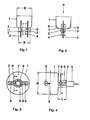
- the lamp vessel 1 shown in a highly schematic form in FIG. 1, has a pinch 2 in which two power supply lines 3 and a pump tube 4 are enclosed.
- the pump tube 4 is guided through the middle part 5 of the pinch 2, which is why the pinch 2 is somewhat thickened at this point (see also FIG. 2).
- the dashed line 6 indicates the shape of the lamp vessel immediately after the squeezing process.
- a certain excess pressure P is exerted on the interior of the lamp vessel 1 by blowing in air, for example, the squeeze jaws still being in the closed position and the glass still softened by the squeezing process. Due to this overpressure P, the end of the lamp vessel 1 is inflated by the amount V and receives the final shape specified by the pinch jaws.
- the one that closes the lamp vessel 1 End face 7 then essentially forms a plane which is arranged at a right angle to the outer surface of the lamp vessel 1. The transition of these two surfaces to one another is essentially in the form of a peripheral edge.
- the length L of the pinch 2 extending from the end face 7 is 0.2 to 0.4 times the outer diameter D of the lamp vessel 1 and the width B of the pinch 2 is smaller than the outer diameter D of the lamp vessel 1.
- the end of the lamp vessel 1 which is separated and shown schematically in FIGS. 3 to 5 has a pinch 2, in which two power supply lines 3 and a pump tube 4 are enclosed.
- a coil 8 is stretched between the current leads 3.
- the vessel melting may belong to an incandescent or discharge lamp, the filament 8 being an incandescent filament of an incandescent lamp or an electrode filament of a low-pressure mercury discharge lamp.
- the pinch 2 encloses the pump tube 4, which has a relatively large diameter, and is made thickened in the central part 5. In the border area of the pinch 2 to the thickened central part 5, a depression is made on each of the side surfaces. The depression is designed as a frustoconical blind hole 9 and touches the pump tube 4.
- the lateral narrow surfaces of the pinch 2, which form the pinch thickness, are each provided with a notch 10.
- a lamp base (not shown) with corresponding cams on its inner circumferential surface snaps into the notch 10, thereby ensuring an additional hold and, if necessary, a torsion resistance of the connection.
- Figure 6 shows only a modified blind hole compared to the previous figures 3 to 5.
- a truncated pyramid-shaped blind hole 11 has been pressed into the pinch 2.
- the edges of the blind hole 11 are rounded in order to avoid tension in the pinch (not visible in the drawing).
- the narrow surfaces of the pinch 2 also have notches 10 here for a better base hold.
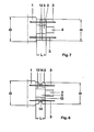
- the depression shown in the pinch 2 of FIG. 7 is designed as a groove 12 in the side face that extends over the entire pinch width - ie also over the thickened central part 5.
- the groove 12 is slightly conical and rounded at the edges (not visible in the illustration).
- the second (rear) side surface also has a groove of the same type.
- the pinch 2 of FIG. 8 is provided on each side surface with two depressions in the form of a T-groove 13.
- the horizontal sections of the T run closely to the edge of the thickened central part 5; however, this remains undeformed.
- the sharp edges of the T-groove 13 within the pinch 2 are preferably rounded.
- the two narrow sides have a recess 14 for a better base hold.
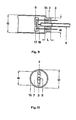
- FIGS. 9 and 10 show an end of a fluorescent lamp provided with a lamp vessel melt according to the invention.
- the end face 7 is here provided with a shoulder 15 of smaller diameter which is arranged concentrically with the outside diameter, as a result of which the base to be put on later sits well centered.
- the holder 16 can be melted in the pinch 2 and end there or it is fused to the pump tube 4. After the lamp has been pumped and filled, the pump tube 4 is cut off gas-tight close to the pinch 2.
- FIGS. Different exemplary embodiments of a capped fluorescent lamp are shown in FIGS.
- the lamp vessel is crushed as described above. Sokkelung in Figure 11 is done in a conventional manner.
- a base sleeve 18 is provided with a base plate 20 containing the riveted base pins 19. The base is then fixed by means of cement 21 on the pinched lamp end.
- the base 22 in FIG. 12 can be made from a plastic. On its inner circumferential surface it is provided with cams 23 with which it engages in the corresponding depression in the pinch 2, thereby ensuring an additional hold and the torsion resistance of the connection.
- the power supplies with the socket pins are in a known manner - e.g. by terminals - electrically connected.
- the base pins 24 have already been electrically connected to the power supply lines 3 before being crimped and then melted into the crimp 2 over part of their length.
- the cover cap 25 merely fulfills the function of mechanical protection for the pinch 2.
- the fluorescent lamp in Figure 14 is provided with a glass base.
- each is from the Quet Schung 2 led out power leads with their end back in an arc to the pinch 2, after which the resulting wire loops 26 are bent to one side of the pinch. Modified sockets are required for this type of fluorescent lamp base.
- the lamp vessel 1 consists of soda-lime glass and has an outer diameter D of approximately 25.5 mm.
- the length L of the pinch is approximately 6 mm and the width B or the thickness is approximately 20 mm or 3 mm.
- the pump tube 4 made of lead glass has an outer diameter of approx. 6 mm, as a result of which the thickened central part 5 increases to approx. 7 mm.
- a truncated cone-shaped blind hole 9 is pressed in on each of the side surfaces.
- the blind hole 9 has a largest diameter of approximately 2 mm and a depth of approximately 1.7 mm.
- grooves 12 or 13 are also provided instead of or in addition to the blind holes 9, these have a greatest width of approximately 2 mm and a depth of approximately 0.4 mm.
- the one-piece power supplies 3 melted into the pinch 2 have a coefficient of thermal expansion adapted to that of the glass.
- An oxidized or possibly boraxed iron-nickel-based wire is particularly suitable for the power supply.
Landscapes
- Engineering & Computer Science (AREA)
- Manufacturing & Machinery (AREA)
- Vessels And Coating Films For Discharge Lamps (AREA)
Applications Claiming Priority (4)
| Application Number | Priority Date | Filing Date | Title |
|---|---|---|---|
| DE3112821 | 1981-03-31 | ||
| DE3112821A DE3112821A1 (de) | 1981-03-31 | 1981-03-31 | Elektrische lampe mit einer als quetschung ausgebildeten gefaesseinschmelzung sowie vorrichtung und verfahren zur herstellung |
| DE3204249 | 1982-02-08 | ||
| DE19823204249 DE3204249A1 (de) | 1982-02-08 | 1982-02-08 | Elektrische lampe mit einer als quetschung ausgebildeten gefaesseinschmelzung |
Publications (3)
| Publication Number | Publication Date |
|---|---|
| EP0061757A2 true EP0061757A2 (fr) | 1982-10-06 |
| EP0061757A3 EP0061757A3 (en) | 1983-05-18 |
| EP0061757B1 EP0061757B1 (fr) | 1986-05-14 |
Family
ID=25792310
Family Applications (1)
| Application Number | Title | Priority Date | Filing Date |
|---|---|---|---|
| EP82102635A Expired EP0061757B1 (fr) | 1981-03-31 | 1982-03-29 | Méthode pour sceller par pincement une lampe éléctrique et dispositif de pincement pour la mise en oeuvre de cette méthode |
Country Status (2)
| Country | Link |
|---|---|
| EP (1) | EP0061757B1 (fr) |
| DE (1) | DE3271115D1 (fr) |
Cited By (7)
| Publication number | Priority date | Publication date | Assignee | Title |
|---|---|---|---|---|
| EP0118100A1 (fr) * | 1983-03-04 | 1984-09-12 | Patent-Treuhand-Gesellschaft für elektrische Glühlampen mbH | Lampe à décharge à basse pression avec culot à un côté |
| DE4024603A1 (de) * | 1990-08-02 | 1992-02-06 | Patent Treuhand Ges Fuer Elektrische Gluehlampen Mbh | Hochdruckentladungslampe |
| EP0821400A2 (fr) * | 1996-07-22 | 1998-01-28 | Koito Manufacturing Co., Ltd. | Lampe électrique avec culot |
| EP0829902A2 (fr) * | 1996-09-16 | 1998-03-18 | Patent-Treuhand-Gesellschaft für elektrische Glühlampen mbH | Lampe électrique |
| EP0877412A1 (fr) * | 1997-05-02 | 1998-11-11 | Osram Sylvania Inc. | Lampe à électrode ou traversée centrée et son procédé de fabrication |
| WO2002027747A1 (fr) * | 2000-09-29 | 2002-04-04 | Patent-Treuhand-Gesellschaft für elektrische Glühlampen mbH | Lampe a decharge avec barriere dielectrique |
| WO2003103011A1 (fr) * | 2002-06-04 | 2003-12-11 | Koninklijke Philips Electronics N.V. | Lampe a decharge a vapeur de mercure et a basse pression et lampe fluorescente compacte |
Citations (4)
| Publication number | Priority date | Publication date | Assignee | Title |
|---|---|---|---|---|
| US2104166A (en) * | 1934-05-01 | 1938-01-04 | Westinghouse Electric & Mfg Co | Method of making a glass seal |
| US2844919A (en) * | 1951-03-21 | 1958-07-29 | Gen Electric | Quartz-to-metal foil press seal |
| CH422153A (de) * | 1963-07-16 | 1966-10-15 | Patent Treuhand Ges Fuer Elektrische Gluehlampen Mbh | Zwerglampe mit als Sockel dienender Flachquetschung |
| DE1236068B (de) * | 1961-11-03 | 1967-03-09 | Patra Patent Treuhand | Verfahren zur Herstellung von elektrischen Kleingluehlampen |
-
1982
- 1982-03-29 DE DE8282102635T patent/DE3271115D1/de not_active Expired
- 1982-03-29 EP EP82102635A patent/EP0061757B1/fr not_active Expired
Patent Citations (4)
| Publication number | Priority date | Publication date | Assignee | Title |
|---|---|---|---|---|
| US2104166A (en) * | 1934-05-01 | 1938-01-04 | Westinghouse Electric & Mfg Co | Method of making a glass seal |
| US2844919A (en) * | 1951-03-21 | 1958-07-29 | Gen Electric | Quartz-to-metal foil press seal |
| DE1236068B (de) * | 1961-11-03 | 1967-03-09 | Patra Patent Treuhand | Verfahren zur Herstellung von elektrischen Kleingluehlampen |
| CH422153A (de) * | 1963-07-16 | 1966-10-15 | Patent Treuhand Ges Fuer Elektrische Gluehlampen Mbh | Zwerglampe mit als Sockel dienender Flachquetschung |
Cited By (11)
| Publication number | Priority date | Publication date | Assignee | Title |
|---|---|---|---|---|
| EP0118100A1 (fr) * | 1983-03-04 | 1984-09-12 | Patent-Treuhand-Gesellschaft für elektrische Glühlampen mbH | Lampe à décharge à basse pression avec culot à un côté |
| DE4024603A1 (de) * | 1990-08-02 | 1992-02-06 | Patent Treuhand Ges Fuer Elektrische Gluehlampen Mbh | Hochdruckentladungslampe |
| EP0821400A2 (fr) * | 1996-07-22 | 1998-01-28 | Koito Manufacturing Co., Ltd. | Lampe électrique avec culot |
| EP0821400A3 (fr) * | 1996-07-22 | 1999-05-26 | Koito Manufacturing Co., Ltd. | Lampe électrique avec culot |
| US5994825A (en) * | 1996-07-22 | 1999-11-30 | Koito Manufacturing Co., Ltd. | Electric lamp with a base |
| EP0829902A2 (fr) * | 1996-09-16 | 1998-03-18 | Patent-Treuhand-Gesellschaft für elektrische Glühlampen mbH | Lampe électrique |
| EP0829902A3 (fr) * | 1996-09-16 | 1999-06-02 | Patent-Treuhand-Gesellschaft für elektrische Glühlampen mbH | Lampe électrique |
| EP0877412A1 (fr) * | 1997-05-02 | 1998-11-11 | Osram Sylvania Inc. | Lampe à électrode ou traversée centrée et son procédé de fabrication |
| WO2002027747A1 (fr) * | 2000-09-29 | 2002-04-04 | Patent-Treuhand-Gesellschaft für elektrische Glühlampen mbH | Lampe a decharge avec barriere dielectrique |
| US6605899B2 (en) | 2000-09-29 | 2003-08-12 | Patent-Treuhand-Gesellschaft Fuer Elektrische Gluehlampen Mbh | Dielectric barrier discharge lamp |
| WO2003103011A1 (fr) * | 2002-06-04 | 2003-12-11 | Koninklijke Philips Electronics N.V. | Lampe a decharge a vapeur de mercure et a basse pression et lampe fluorescente compacte |
Also Published As
| Publication number | Publication date |
|---|---|
| EP0061757A3 (en) | 1983-05-18 |
| EP0061757B1 (fr) | 1986-05-14 |
| DE3271115D1 (en) | 1986-06-19 |
Similar Documents
| Publication | Publication Date | Title |
|---|---|---|
| DE2212536C2 (de) | Verfahren zur Herstellung von Leuchtstofflampen | |
| DE102005013759A1 (de) | Lampe mit Stromzuführung und Elektrode | |
| DE69305586T2 (de) | Elektrische Lampe | |
| DE3907277A1 (de) | Quecksilberniederdruckentladungslampe | |
| EP0061757B1 (fr) | Méthode pour sceller par pincement une lampe éléctrique et dispositif de pincement pour la mise en oeuvre de cette méthode | |
| WO2010124904A1 (fr) | Lampe à décharge | |
| DE3112821A1 (de) | Elektrische lampe mit einer als quetschung ausgebildeten gefaesseinschmelzung sowie vorrichtung und verfahren zur herstellung | |
| DE69712833T2 (de) | Bogenentladungsröhre für Entladungslampenvorrichtung | |
| EP0758142A2 (fr) | Lampe à incandescence halogène | |
| EP0813229A2 (fr) | Procédé de fabrication d'une lampe à incandescence halogène | |
| DE1234313B (de) | Verfahren zur Herstellung einer Schweissverbindung zwischen den Strom-zuleitungsdraehten und den Sockelkontakten einer elektrischen Lampe | |
| EP2342737B1 (fr) | Lampe à incandescence à halogène pour le fonctionnement sur la tension du réseau | |
| DE69110097T2 (de) | Elektrische Glühlampe. | |
| EP0591777A2 (fr) | Méthode de fabrication d'une lampe à décharge à haute pression de faible puissance à pincement unique et lampes à décharge à haute pression | |
| EP0718869A1 (fr) | Lampe à décharge à basse pression | |
| EP1730766A2 (fr) | Systeme d'electrodes pour lampe a decharge gazeuse haute pression | |
| DE10256389A1 (de) | Metallhalogenidlampe mit keramischem Entladungsgefäß | |
| EP0588201A2 (fr) | Lampe à décharge haute pression et procédé pour la fabrication d'une lampe à décharge à haute pression | |
| DE839831C (de) | Stromdurchfuehrung | |
| DE1589094A1 (de) | Miniaturgluehlampen u. dgl. und Verfahren zu deren Herstellung | |
| DE2909259A1 (de) | Wolfram-halogen-lampe fuer einen monoblock-scheinwerfer sowie methode zu ihrer herstellung | |
| EP0219861A2 (fr) | Méthode de fabrication d'une lampe à décharge à haute pression à halogénures de métal à pincement unique et une lampe fabriquée suivant cette méthode | |
| EP0219860A2 (fr) | Méthode de fabrication d'une lampe à décharge à haute pression à halogénures de métal à pincement unique et une lampe fabriquée suivant cette méthode | |
| DE1067930B (fr) | ||
| DE19647827B4 (de) | Verfahren zur Herstellung einer Leuchtstofflampe |
Legal Events
| Date | Code | Title | Description |
|---|---|---|---|
| PUAI | Public reference made under article 153(3) epc to a published international application that has entered the european phase |
Free format text: ORIGINAL CODE: 0009012 |
|
| AK | Designated contracting states |
Designated state(s): DE FR GB IT |
|
| PUAL | Search report despatched |
Free format text: ORIGINAL CODE: 0009013 |
|
| AK | Designated contracting states |
Designated state(s): DE FR GB IT |
|
| 17P | Request for examination filed |
Effective date: 19831109 |
|
| GRAA | (expected) grant |
Free format text: ORIGINAL CODE: 0009210 |
|
| AK | Designated contracting states |
Kind code of ref document: B1 Designated state(s): DE FR GB IT |
|
| ITF | It: translation for a ep patent filed | ||
| ET | Fr: translation filed | ||
| REF | Corresponds to: |
Ref document number: 3271115 Country of ref document: DE Date of ref document: 19860619 |
|
| PLBE | No opposition filed within time limit |
Free format text: ORIGINAL CODE: 0009261 |
|
| STAA | Information on the status of an ep patent application or granted ep patent |
Free format text: STATUS: NO OPPOSITION FILED WITHIN TIME LIMIT |
|
| 26N | No opposition filed | ||
| ITTA | It: last paid annual fee | ||
| PGFP | Annual fee paid to national office [announced via postgrant information from national office to epo] |
Ref country code: GB Payment date: 19950213 Year of fee payment: 14 |
|
| PGFP | Annual fee paid to national office [announced via postgrant information from national office to epo] |
Ref country code: FR Payment date: 19950323 Year of fee payment: 14 |
|
| PGFP | Annual fee paid to national office [announced via postgrant information from national office to epo] |
Ref country code: DE Payment date: 19950518 Year of fee payment: 14 |
|
| PG25 | Lapsed in a contracting state [announced via postgrant information from national office to epo] |
Ref country code: GB Effective date: 19960329 |
|
| GBPC | Gb: european patent ceased through non-payment of renewal fee |
Effective date: 19960329 |
|
| PG25 | Lapsed in a contracting state [announced via postgrant information from national office to epo] |
Ref country code: FR Effective date: 19961129 |
|
| PG25 | Lapsed in a contracting state [announced via postgrant information from national office to epo] |
Ref country code: DE Effective date: 19961203 |
|
| REG | Reference to a national code |
Ref country code: FR Ref legal event code: ST |