EP0829902A2 - Lampe électrique - Google Patents
Lampe électrique Download PDFInfo
- Publication number
- EP0829902A2 EP0829902A2 EP97110890A EP97110890A EP0829902A2 EP 0829902 A2 EP0829902 A2 EP 0829902A2 EP 97110890 A EP97110890 A EP 97110890A EP 97110890 A EP97110890 A EP 97110890A EP 0829902 A2 EP0829902 A2 EP 0829902A2
- Authority
- EP
- European Patent Office
- Prior art keywords
- foot
- lamp
- electric lamp
- base
- intermediate walls
- Prior art date
- Legal status (The legal status is an assumption and is not a legal conclusion. Google has not performed a legal analysis and makes no representation as to the accuracy of the status listed.)
- Ceased
Links
Images


Classifications
-
- H—ELECTRICITY
- H01—ELECTRIC ELEMENTS
- H01K—ELECTRIC INCANDESCENT LAMPS
- H01K1/00—Details
- H01K1/42—Means forming part of the lamp for the purpose of providing electrical connection, or support for, the lamp
- H01K1/46—Means forming part of the lamp for the purpose of providing electrical connection, or support for, the lamp supported by a separate part, e.g. base, cap
Definitions
- the invention relates to an electric lamp according to the preamble of claim 1.
- Patent EP 0 123 104 describes a halogen incandescent lamp with a lamp bulb which has a pinch foot.
- the squeeze foot is inserted bayonet-like in the lamp base and clamped between two intermediate walls arranged in a recess in the base, which resiliently abut the broad sides of the squeeze foot.
- neither the base nor the pinch foot of the lamp bulb are provided with guide elements which ensure an axial alignment of the lamp bulb in the base when the pinch foot is inserted into the base.
- the pump stem runs in the pinch foot of the lamp bulb and forms at least one bead on the pinch foot.
- At least one of the intermediate walls arranged in the base, which clamps against the pinch foot, is provided with a recess matched to this bead, so that the bead or the pump stem serves as a guide bar when the lamp is attached.
- the squeeze foot thickness outside the stem is smaller than the outside diameter of the stem, so that the stem forms a bead on each of the squeeze foot surfaces, which engages in matching recesses in the two intermediate walls.
- the squeeze foot and the partition walls advantageously form a snap or snap connection, which is advantageously realized by means of at least one groove running transversely over the squeeze foot and at least one transverse rib on the partition walls matched to the at least one groove.
- the base advantageously has sliding contacts.
- the lamp base is advantageously designed as a plug and therefore has plug contacts.
- the lamps according to the two exemplary embodiments are incandescent lamps, which can be used, for example, as a taillight or flashing light in a motor vehicle.
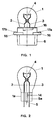
- FIGS 1 to 4 show details of the first embodiment of the invention.
- This lamp has a glass lamp bulb 1, which is closed at one end by means of a squeezing foot 1a.
- Two power leads 2, 3 are led out of the squeezing foot 1a and are electrically conductively connected to a filament 4 arranged in the interior of the lamp bulb 1.
- a melted pump stem 5 also runs through the squeezing foot 1 a and was used to rinse the interior of the lamp bulb 1 during the manufacture of the lamp.
- the pump stem 5 runs between the power supply lines 2, 3 and is arranged approximately axially.
- the thickness of the squeezing foot 1a is smaller than the outside diameter of the pumping stem 5, so that the pumping stem 5 forms a longitudinally extending bead 5a on both squeezing foot surfaces or on both broad sides of the squeezing foot 1a.
- the lamp base 6 is made of plastic. It has a cuboid-like receptacle 7, in which two free-standing partitions 8, 9 are arranged, which, after the lamp bulb 1 has been inserted, are clamped against the pinch foot 1 a of the lamp. The distance between these partitions 8, 9 is matched to the squeeze foot thickness. Furthermore, the intermediate walls 8, 9 are each provided with a recess 10, 11 matched to the beads 5a. With the help of two transverse ribs 12, 13 attached to the intermediate walls 8, 9 and two matching grooves 14 in the squeezing foot 1 a, the intermediate walls 8, 9 of the lamp base 6 and the squeezing foot 1 a form a snap or snap connection.
- the base 6 is provided with a plurality of flanges 16, which are used for mounting the printed circuit board, and with two laterally from the base 6 out sliding contacts 17a, 17b, each of which is electrically conductively connected to one of the power supply lines 2, 3.
- the second embodiment differs from the first embodiment only in the lamp base 20.
- the lamp base of the second embodiment is also made of plastic. It has a parallelepiped-like receptacle 21, in which two free-standing partitions 22, 23 are arranged, which, after the lamp bulb 1 has been inserted, bear against the pinch foot 1 a of the lamp. The distance between these partitions 22, 23 is matched to the squeeze foot thickness.
- the intermediate walls 22, 23 are each provided with a recess 24, 25 matched to the pump stem 5 or to the bead 5a.
- the intermediate walls 22, 23 of the lamp base 20 and the squeezing foot 1 a form a snap or snap connection.
- the base 20 is equipped with a plurality of flanges 28 which are used to fasten the lamp in a lamp holder.
- the lower part of the base 20 facing away from the lamp bulb 1 is designed as a plug provided with two metallic contact pins 29a, 29b.
- the contact pins 29a, 29b are each electrically conductively connected to one of the current leads 2, 3 led out of the lamp bulb 1.
Landscapes
- Reciprocating Pumps (AREA)
- Fastening Of Light Sources Or Lamp Holders (AREA)
- Liquid Developers In Electrophotography (AREA)
- Circuit Arrangements For Discharge Lamps (AREA)
- Glass Compositions (AREA)
Applications Claiming Priority (2)
| Application Number | Priority Date | Filing Date | Title |
|---|---|---|---|
| DE29616116U DE29616116U1 (de) | 1996-09-16 | 1996-09-16 | Elektrische Lampe |
| DE29616116U | 1996-09-16 |
Publications (2)
| Publication Number | Publication Date |
|---|---|
| EP0829902A2 true EP0829902A2 (fr) | 1998-03-18 |
| EP0829902A3 EP0829902A3 (fr) | 1999-06-02 |
Family
ID=8029289
Family Applications (1)
| Application Number | Title | Priority Date | Filing Date |
|---|---|---|---|
| EP97110890A Ceased EP0829902A3 (fr) | 1996-09-16 | 1997-07-02 | Lampe électrique |
Country Status (2)
| Country | Link |
|---|---|
| EP (1) | EP0829902A3 (fr) |
| DE (1) | DE29616116U1 (fr) |
Cited By (1)
| Publication number | Priority date | Publication date | Assignee | Title |
|---|---|---|---|---|
| WO2007110320A3 (fr) * | 2006-03-28 | 2007-11-22 | Patent Treuhand Ges Fuer Elektrische Gluehlampen Mbh | Lampe électrique |
Families Citing this family (2)
| Publication number | Priority date | Publication date | Assignee | Title |
|---|---|---|---|---|
| DE19752979A1 (de) | 1997-11-28 | 1999-06-02 | Patent Treuhand Ges Fuer Elektrische Gluehlampen Mbh | Elektrische Lampe und Beleuchtungssystem für derartige Lampen |
| DE19843506A1 (de) * | 1998-09-23 | 2000-03-30 | Patent Treuhand Ges Fuer Elektrische Gluehlampen Mbh | Elektrische Lampe |
Family Cites Families (9)
| Publication number | Priority date | Publication date | Assignee | Title |
|---|---|---|---|---|
| US3510718A (en) * | 1967-11-06 | 1970-05-05 | Sylvania Electric Prod | Incandescent lamp |
| GB1464598A (en) * | 1974-02-19 | 1977-02-16 | Carr Fastener Co Ltd | Lampholder for wedge base lamps |
| JPS5422386U (fr) * | 1977-07-18 | 1979-02-14 | ||
| US4146814A (en) * | 1978-05-01 | 1979-03-27 | General Electric Company | Pinch and base structure for single-ended lamps |
| JPS5624753A (en) * | 1979-08-01 | 1981-03-09 | Tokyo Shibaura Electric Co | Baseeless bulb unit |
| JPS5688274A (en) * | 1979-12-20 | 1981-07-17 | Tokyo Shibaura Electric Co | Light source |
| EP0061757B1 (fr) * | 1981-03-31 | 1986-05-14 | Patent-Treuhand-Gesellschaft für elektrische Glühlampen mbH | Méthode pour sceller par pincement une lampe éléctrique et dispositif de pincement pour la mise en oeuvre de cette méthode |
| DE8311269U1 (de) * | 1983-04-15 | 1984-09-20 | Patent-Treuhand-Gesellschaft für elektrische Glühlampen mbH, 8000 München | Leuchte zum bajonettartigen einbau in eine anzeigeeinrichtung |
| US4940422A (en) * | 1989-05-17 | 1990-07-10 | Zanxx, Inc. | Low profile lamp socket assembly |
-
1996
- 1996-09-16 DE DE29616116U patent/DE29616116U1/de not_active Expired - Lifetime
-
1997
- 1997-07-02 EP EP97110890A patent/EP0829902A3/fr not_active Ceased
Cited By (1)
| Publication number | Priority date | Publication date | Assignee | Title |
|---|---|---|---|---|
| WO2007110320A3 (fr) * | 2006-03-28 | 2007-11-22 | Patent Treuhand Ges Fuer Elektrische Gluehlampen Mbh | Lampe électrique |
Also Published As
| Publication number | Publication date |
|---|---|
| EP0829902A3 (fr) | 1999-06-02 |
| DE29616116U1 (de) | 1996-12-12 |
Similar Documents
| Publication | Publication Date | Title |
|---|---|---|
| DE10065542C2 (de) | Kraftfahrzeug-Lampeneinheit und Verfahren zur Herstellung derselben | |
| DE3210005A1 (de) | Kompakte fluoreszenzlampe | |
| DE2754619A1 (de) | Elektrische anschlussvorrichtung und verfahren zu ihrer herstellung | |
| DE3435822A1 (de) | Klinkensteckbuchse mit eingebetteten kontaktelementen | |
| DE4241934A1 (fr) | ||
| DE68912002T2 (de) | Elektrische Lampe. | |
| DE2828146A1 (de) | Elektrische leiterplatte | |
| EP0179473A2 (fr) | Adaptateur pour une lampe à décharge à basse pression à culot unique | |
| EP0854497B1 (fr) | Lampe compacte à décharge basse pression | |
| EP0829902A2 (fr) | Lampe électrique | |
| EP0060900B1 (fr) | Bloc optique compartimenté pour véhicule | |
| DE19850892C2 (de) | Rückleuchteneinheit | |
| EP0909467B1 (fr) | Petite lampe a incandescence et support pour une telle lampe | |
| DE69501475T2 (de) | Signalleuchte mit mehreren Lampen für Fahrzeuge | |
| DE4403181A1 (de) | Elektrische Klemmkontakt-Kabelschuhvorrichtung | |
| EP0923105B1 (fr) | Lampe à décharge à basse pression de type compact | |
| DE7311111U (de) | Elektrische Kontaktklemme | |
| DE3531072C2 (fr) | ||
| DE60021990T2 (de) | Elektrische lampe | |
| EP0945671B1 (fr) | Porte lampe de feux pour véhicule | |
| DE4316271C2 (de) | Beleuchtungsvorrichtung für Kleinstleuchtstofflampen | |
| DE19801409B4 (de) | Verfahren zur Herstellung von sich aus einem ersten und einem zweiten Verbinderteil zusammensetzenden Steckverbindern | |
| DE8905767U1 (de) | Sockel für eine Kleinglühlampe | |
| DE3332762A1 (de) | Lampentraeger | |
| DE202023002777U1 (de) | Federkraftklemme und elektrische Vorrichtung |
Legal Events
| Date | Code | Title | Description |
|---|---|---|---|
| PUAI | Public reference made under article 153(3) epc to a published international application that has entered the european phase |
Free format text: ORIGINAL CODE: 0009012 |
|
| AK | Designated contracting states |
Kind code of ref document: A2 Designated state(s): BE DE ES FR GB IT NL |
|
| PUAL | Search report despatched |
Free format text: ORIGINAL CODE: 0009013 |
|
| AK | Designated contracting states |
Kind code of ref document: A3 Designated state(s): AT BE CH DE DK ES FI FR GB GR IE IT LI LU MC NL PT SE |
|
| AKX | Designation fees paid |
Free format text: BE DE ES FR GB IT NL |
|
| 17P | Request for examination filed |
Effective date: 20000126 |
|
| 17Q | First examination report despatched |
Effective date: 20031112 |
|
| STAA | Information on the status of an ep patent application or granted ep patent |
Free format text: STATUS: THE APPLICATION HAS BEEN REFUSED |
|
| 18R | Application refused |
Effective date: 20050925 |