EP0829902A2 - Electric lamp - Google Patents
Electric lamp Download PDFInfo
- Publication number
- EP0829902A2 EP0829902A2 EP97110890A EP97110890A EP0829902A2 EP 0829902 A2 EP0829902 A2 EP 0829902A2 EP 97110890 A EP97110890 A EP 97110890A EP 97110890 A EP97110890 A EP 97110890A EP 0829902 A2 EP0829902 A2 EP 0829902A2
- Authority
- EP
- European Patent Office
- Prior art keywords
- foot
- lamp
- electric lamp
- base
- intermediate walls
- Prior art date
- Legal status (The legal status is an assumption and is not a legal conclusion. Google has not performed a legal analysis and makes no representation as to the accuracy of the status listed.)
- Ceased
Links
Images


Classifications
-
- H—ELECTRICITY
- H01—ELECTRIC ELEMENTS
- H01K—ELECTRIC INCANDESCENT LAMPS
- H01K1/00—Details
- H01K1/42—Means forming part of the lamp for the purpose of providing electrical connection, or support for, the lamp
- H01K1/46—Means forming part of the lamp for the purpose of providing electrical connection, or support for, the lamp supported by a separate part, e.g. base, cap
Definitions
- the invention relates to an electric lamp according to the preamble of claim 1.
- Patent EP 0 123 104 describes a halogen incandescent lamp with a lamp bulb which has a pinch foot.
- the squeeze foot is inserted bayonet-like in the lamp base and clamped between two intermediate walls arranged in a recess in the base, which resiliently abut the broad sides of the squeeze foot.
- neither the base nor the pinch foot of the lamp bulb are provided with guide elements which ensure an axial alignment of the lamp bulb in the base when the pinch foot is inserted into the base.
- the pump stem runs in the pinch foot of the lamp bulb and forms at least one bead on the pinch foot.
- At least one of the intermediate walls arranged in the base, which clamps against the pinch foot, is provided with a recess matched to this bead, so that the bead or the pump stem serves as a guide bar when the lamp is attached.
- the squeeze foot thickness outside the stem is smaller than the outside diameter of the stem, so that the stem forms a bead on each of the squeeze foot surfaces, which engages in matching recesses in the two intermediate walls.
- the squeeze foot and the partition walls advantageously form a snap or snap connection, which is advantageously realized by means of at least one groove running transversely over the squeeze foot and at least one transverse rib on the partition walls matched to the at least one groove.
- the base advantageously has sliding contacts.
- the lamp base is advantageously designed as a plug and therefore has plug contacts.
- the lamps according to the two exemplary embodiments are incandescent lamps, which can be used, for example, as a taillight or flashing light in a motor vehicle.
- FIGS 1 to 4 show details of the first embodiment of the invention.
- This lamp has a glass lamp bulb 1, which is closed at one end by means of a squeezing foot 1a.
- Two power leads 2, 3 are led out of the squeezing foot 1a and are electrically conductively connected to a filament 4 arranged in the interior of the lamp bulb 1.
- a melted pump stem 5 also runs through the squeezing foot 1 a and was used to rinse the interior of the lamp bulb 1 during the manufacture of the lamp.
- the pump stem 5 runs between the power supply lines 2, 3 and is arranged approximately axially.
- the thickness of the squeezing foot 1a is smaller than the outside diameter of the pumping stem 5, so that the pumping stem 5 forms a longitudinally extending bead 5a on both squeezing foot surfaces or on both broad sides of the squeezing foot 1a.
- the lamp base 6 is made of plastic. It has a cuboid-like receptacle 7, in which two free-standing partitions 8, 9 are arranged, which, after the lamp bulb 1 has been inserted, are clamped against the pinch foot 1 a of the lamp. The distance between these partitions 8, 9 is matched to the squeeze foot thickness. Furthermore, the intermediate walls 8, 9 are each provided with a recess 10, 11 matched to the beads 5a. With the help of two transverse ribs 12, 13 attached to the intermediate walls 8, 9 and two matching grooves 14 in the squeezing foot 1 a, the intermediate walls 8, 9 of the lamp base 6 and the squeezing foot 1 a form a snap or snap connection.
- the base 6 is provided with a plurality of flanges 16, which are used for mounting the printed circuit board, and with two laterally from the base 6 out sliding contacts 17a, 17b, each of which is electrically conductively connected to one of the power supply lines 2, 3.
- the second embodiment differs from the first embodiment only in the lamp base 20.
- the lamp base of the second embodiment is also made of plastic. It has a parallelepiped-like receptacle 21, in which two free-standing partitions 22, 23 are arranged, which, after the lamp bulb 1 has been inserted, bear against the pinch foot 1 a of the lamp. The distance between these partitions 22, 23 is matched to the squeeze foot thickness.
- the intermediate walls 22, 23 are each provided with a recess 24, 25 matched to the pump stem 5 or to the bead 5a.
- the intermediate walls 22, 23 of the lamp base 20 and the squeezing foot 1 a form a snap or snap connection.
- the base 20 is equipped with a plurality of flanges 28 which are used to fasten the lamp in a lamp holder.
- the lower part of the base 20 facing away from the lamp bulb 1 is designed as a plug provided with two metallic contact pins 29a, 29b.
- the contact pins 29a, 29b are each electrically conductively connected to one of the current leads 2, 3 led out of the lamp bulb 1.
Landscapes
- Reciprocating Pumps (AREA)
- Fastening Of Light Sources Or Lamp Holders (AREA)
- Liquid Developers In Electrophotography (AREA)
- Circuit Arrangements For Discharge Lamps (AREA)
- Glass Compositions (AREA)
Abstract
Die Erfindung betrifft eine elektrische Lampe mit einem Lampenkolben (1), der einen Quetschfuß (1a) aufweist, und mit mindestens zwei aus dem Quetschfuß (1a) herausragenden Stromzuführungen (2, 3) sowie mit einem mit einer Aufnahme (7; 21) für den Quetschfuß (1a) versehenen Sockel (6; 20), der zwei in der Aufnahme (7; 21) angeordnete Zwischenwände (8, 9; 22, 23) besitzt, zwischen denen der Quetschfuß (1a) klemmend fixiert ist, wobei die Lampe einen im Quetschfuß (1a) verlaufenden Pumpstengel (5) aufweist. Der Pumpstengel (5) bildet auf dem Quetschfuß (1a) einen Wulst (5a) und die Zwischenwände (8, 9; 22, 23) besitzen eine auf den Wulst (5a) abgestimmte Aussparung (10, 11; 24, 25).
Description
Die Erfindung betrifft eine elektrische Lampe gemäß dem Oberbegriff des Schutzanspruchs 1.The invention relates to an electric lamp according to the preamble of
Das Patent EP 0 123 104 beschreibt eine Halogenglühlampe mit einem Lampenkolben, der einen Quetschfuß aufweist. Der Quetschfuß ist bajonettartig in den Lampensockel eingesetzt und klemmend zwischen zwei in einer Aussparung des Sockels angeordneten Zwischenwänden fixiert, die federnd an den Breitseiten des Quetschfußes anliegen. Bei dieser Lampe sind weder der Sockel noch der Quetschfuß des Lampenkolbens mit Führungselementen versehen, die beim Einsetzen des Quetschfußes in den Sockel eine axiale Ausrichtung des Lampenkolbens im Sockel gewährleisten.Patent EP 0 123 104 describes a halogen incandescent lamp with a lamp bulb which has a pinch foot. The squeeze foot is inserted bayonet-like in the lamp base and clamped between two intermediate walls arranged in a recess in the base, which resiliently abut the broad sides of the squeeze foot. With this lamp, neither the base nor the pinch foot of the lamp bulb are provided with guide elements which ensure an axial alignment of the lamp bulb in the base when the pinch foot is inserted into the base.
Es ist die Aufgabe der Erfindung, eine elektrische Lampe mit einem verbesserten Sockel bereitzustellen.It is the object of the invention to provide an electric lamp with an improved base.
Diese Aufgabe wird erfindungsgemäß durch die kennzeichnenden Merkmale des Schutzanspruchs 1 gelöst. Besonders vorteilhafte Ausführungen der Erfindung sind in den Unteransprüchen beschrieben.This object is achieved by the characterizing features of
Bei der erfindungsgemäßen Lampe verläuft der Pumpstengel im Quetschfuß des Lampenkolbens und bildet auf dem Quetschfuß zumindest einen Wulst. Wenigstens eine der im Sockel angeordneten, klemmend am Quetschfuß anliegenden Zwischenwände ist mit einer auf diesen Wulst abgestimmten Aussparung versehen, so daß der Wulst bzw. der Pumpstengel beim Sockeln der Lampe als Führungssteg dient. Dadurch wird beim Einsetzen des Quetschfußes in den Sockel auf einfache Weise eine Justage des Lampenkolbens im Sockel gewährleistet. Vorteilhafterweise ist die Quetschfußdicke außerhalb des Pumpstengels kleiner als der Außendurchmesser des Pumpstengels, so daß der Pumpstengel auf beiden Quetschfußoberflächen jeweils einen Wulst bildet, der in darauf abgestimmte Aussparungen der beiden Zwischenwände greift. Der Quetschfuß und die Zwischenwände bilden vorteilhafterweise eine Schnapp- oder Rastverbindung, die vorteilhafterweise mittels mindestens einer quer über den Quetschfuß verlaufenden Nut und wenigstens einer auf die mindestens eine Nut abgestimmten Querrippe auf den Zwischenwänden realisiert ist. Zur Montage der Lampe auf einer Leiter- oder Montageplatte weist der Sockel vorteilhafterweise Schleifkontakte auf. Für andere Anwendungen ist der Lampensockel vorteilhafterweise als Stecker ausgebildet und weist daher Steckkontakte auf.In the lamp according to the invention, the pump stem runs in the pinch foot of the lamp bulb and forms at least one bead on the pinch foot. At least one of the intermediate walls arranged in the base, which clamps against the pinch foot, is provided with a recess matched to this bead, so that the bead or the pump stem serves as a guide bar when the lamp is attached. This will when the Pinch foot in the base ensures an easy adjustment of the lamp bulb in the base. Advantageously, the squeeze foot thickness outside the stem is smaller than the outside diameter of the stem, so that the stem forms a bead on each of the squeeze foot surfaces, which engages in matching recesses in the two intermediate walls. The squeeze foot and the partition walls advantageously form a snap or snap connection, which is advantageously realized by means of at least one groove running transversely over the squeeze foot and at least one transverse rib on the partition walls matched to the at least one groove. To mount the lamp on a circuit board or mounting plate, the base advantageously has sliding contacts. For other applications, the lamp base is advantageously designed as a plug and therefore has plug contacts.
Nachstehend wird die Erfindung anhand zweier bevorzugter Ausführungsbeispiele näher erläutert. Es zeigen:
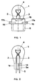
Figur 1- Eine Seitenansicht der erfindungsgemäßen Lampe gemäß des ersten bevorzugten Ausführungsbeispiels
Figur 2- Den Lampenkolben der Lampe gemäß des ersten Ausführungsbeispiels
Figur 3- Eine Draufsicht auf den Sockel des ersten Ausführungsbeispiels
Figur 4- Einen Querschnitt durch den Sockel des ersten Ausführungsbeispiels
Figur 5- Eine Seitenansicht der erfindungsgemäßen Lampe gemäß des zweiten bevorzugten Ausführungsbeispiels
Figur 6- Eine Draufsicht auf den Sockel des zweiten Ausführungsbeispiels
- Figure 1
- A side view of the lamp according to the invention according to the first preferred embodiment
- Figure 2
- The lamp bulb of the lamp according to the first embodiment
- Figure 3
- A top view of the base of the first embodiment
- Figure 4
- A cross section through the base of the first embodiment
- Figure 5
- A side view of the lamp according to the invention according to the second preferred embodiment
- Figure 6
- A top view of the base of the second embodiment
Bei den Lampen gemäß der beiden Ausführungsbeispiele handelt es sich um Glühlampen, die beispielsweise als Rücklicht oder Blinklicht in einem Kraftfahrzeug verwendet werden können.The lamps according to the two exemplary embodiments are incandescent lamps, which can be used, for example, as a taillight or flashing light in a motor vehicle.
In den Figuren 1 bis 4 sind Einzelheiten des ersten Ausführungsbeispiels der Erfindung abgebildet. Diese Lampe besitzt einen gläsernen Lampenkolben 1, der an einem Ende mittels eines Quetschfußes 1a verschlossen ist. Aus dem Quetschfuß 1a sind zwei Stromzuführungen 2, 3 herausgeführt, die elektrisch leitend mit einer Im Innenraum des Lampenkolbens 1 angeordneten Glühwendel 4 verbunden sind. Durch den Quetschfuß 1a verläuft außerdem ein abgeschmolzener Pumpstengel 5, der während der Herstellung der Lampe zum Spülen des Innenraumes des Lampenkolbens 1 diente. Der Pumpstengel 5 verläuft zwischen den Stromzuführungen 2, 3 und ist annähernd axial angeordnet. Außerhalb des Pumpstengels 5 ist die Dicke des Quetschfußes 1a kleiner als der Außendurchmesser des Pumpstengels 5, so daß der Pumpstengel 5 auf beiden Quetschfußoberflächen bzw. auf beiden Breitseiten des Quetschfußes 1a einen in Längsrichtung verlaufenden Wulst 5a bildet.Figures 1 to 4 show details of the first embodiment of the invention. This lamp has a
Der Lampensockel 6 besteht aus Kunststoff. Er besitzt eine quaderartige Aufnahme 7, in der zwei freistehende Zwischenwände 8, 9 angeordnet sind, die nach dem Einsetzen des Lampenkolbens 1 klemmend am Quetschfuß 1a der Lampe anliegen. Der Abstand dieser Zwischenwände 8, 9 ist auf die Quetschfußdicke abgestimmt. Ferner sind die Zwischenwände 8, 9 jeweils mit einer auf die Wülste 5a abgestimmten Aussparung 10, 11 versehen. Mit Hilfe zweier an den Zwischenwänden 8, 9 angebrachter Querrippen 12, 13 und zweier darauf abgestimmter Nuten 14 im Quetschfuß 1a bilden die Zwischenwände 8, 9 des Lampensockels 6 und der Quetschfuß 1a eine Schnapp- bzw. Rastverbindung. Der Sockel 6 ist mit mehreren Flanschen 16, die zur Leiterplattenmontage dienen, und mit zwei seitlich aus dem Sockel 6 herausgeführten Schleifkontakten 17a, 17b, die jeweils mit einer der Stromzuführungen 2, 3 elektrisch leitend verbunden sind, ausgestattet.The
Das zweite Ausführungsbeispiel unterscheidet sich vom ersten Ausführungsbeispiel nur durch den Lampensockel 20. Der Lampensockel des zweiten Ausführungsbeispiels besteht ebenfalls aus Kunststoff. Er besitzt eine quaderartige Aufnahme 21, in der zwei freistehende Zwischenwände 22, 23 angeordnet sind, die nach dem Einsetzen des Lampenkolbens 1 klemmend am Quetschfuß 1a der Lampe anliegen. Der Abstand dieser Zwischenwände 22, 23 ist auf die Quetschfußdicke abgestimmt. Ferner sind die Zwischenwände 22, 23 jeweils mit einer auf den Pumpstengel 5 bzw. auf den Wulst 5a abgestimmten Aussparung 24, 25 versehen. Mit Hilfe zweier an den Zwischenwänden 22, 23 angebrachter Querrippen 26, 27 und zweier darauf abgestimmter Nuten 14 im Quetschfuß 1a bilden die Zwischenwände 22, 23 des Lampensockels 20 und der Quetschfuß 1a eine Schnapp- bzw. Rastverbindung. Der Sockel 20 ist mit mehreren Flanschen 28 ausgestattet, die zur Befestigung der Lampe in einer Lampenfassung dienen. Außerdem ist das vom Lampenkolben 1 abgewandte Unterteil des Sockels 20 als mit zwei metallischen Kontaktstiften 29a, 29b versehener Stecker ausgebildet. Die Kontaktstifte 29a, 29b sind jeweils mit einer der aus dem Lampenkolben 1 herausgeführten Stromzuführungen 2, 3 elektrisch leitend verbunden. Zwischen den Zwischenwänden 22, 23 befinden sich im Boden der quaderförmigen Aussparung 21 zwei Bohrungen 30a, 30b, durch die jeweils eine der Stromzuführungen 2, 3 während der Sockelung hindurchgefädelt wird, um die elektrische Verbindung zu den Kontaktstiften herzustellen.The second embodiment differs from the first embodiment only in the
Claims (7)
dadurch gekennzeichnet, daß der Pumpstengel (5) auf dem Quetschfuß (1a) zumindest einen Wulst (5a) bildet und wenigstens eine Zwischenwand (8, 9; 22, 23) eine auf den Wulst (5a) abgestimmte Aussparung (10, 11; 24, 25) besitzt.Electric lamp with a lamp bulb (1) which has a squeeze foot (1a) and with at least two power leads (2, 3) protruding from the squeeze foot (1a) and with one with a receptacle (7; 21) for the squeeze foot (1a ) provided base (6; 20), which has two intermediate walls (8, 9; 22, 23) arranged in the receptacle (7; 21), between which the squeeze foot (1a) is fixed in a clamped manner, the lamp holding one in the squeeze foot ( 1a) has a running pump stem (5),
characterized in that the pump stem (5) forms at least one bead (5a) on the pinch foot (1a) and at least one intermediate wall (8, 9; 22, 23) has a recess (10, 11; 24) matched to the bead (5a) , 25) has.
Applications Claiming Priority (2)
| Application Number | Priority Date | Filing Date | Title |
|---|---|---|---|
| DE29616116U DE29616116U1 (en) | 1996-09-16 | 1996-09-16 | Electric lamp |
| DE29616116U | 1996-09-16 |
Publications (2)
| Publication Number | Publication Date |
|---|---|
| EP0829902A2 true EP0829902A2 (en) | 1998-03-18 |
| EP0829902A3 EP0829902A3 (en) | 1999-06-02 |
Family
ID=8029289
Family Applications (1)
| Application Number | Title | Priority Date | Filing Date |
|---|---|---|---|
| EP97110890A Ceased EP0829902A3 (en) | 1996-09-16 | 1997-07-02 | Electric lamp |
Country Status (2)
| Country | Link |
|---|---|
| EP (1) | EP0829902A3 (en) |
| DE (1) | DE29616116U1 (en) |
Cited By (1)
| Publication number | Priority date | Publication date | Assignee | Title |
|---|---|---|---|---|
| WO2007110320A3 (en) * | 2006-03-28 | 2007-11-22 | Patent Treuhand Ges Fuer Elektrische Gluehlampen Mbh | Electric lamp |
Families Citing this family (2)
| Publication number | Priority date | Publication date | Assignee | Title |
|---|---|---|---|---|
| DE19752979A1 (en) | 1997-11-28 | 1999-06-02 | Patent Treuhand Ges Fuer Elektrische Gluehlampen Mbh | Electric lamp and lighting system for such lamps |
| DE19843506A1 (en) * | 1998-09-23 | 2000-03-30 | Patent Treuhand Ges Fuer Elektrische Gluehlampen Mbh | Electric lamp |
Family Cites Families (9)
| Publication number | Priority date | Publication date | Assignee | Title |
|---|---|---|---|---|
| US3510718A (en) * | 1967-11-06 | 1970-05-05 | Sylvania Electric Prod | Incandescent lamp |
| GB1464598A (en) * | 1974-02-19 | 1977-02-16 | Carr Fastener Co Ltd | Lampholder for wedge base lamps |
| JPS5422386U (en) * | 1977-07-18 | 1979-02-14 | ||
| US4146814A (en) * | 1978-05-01 | 1979-03-27 | General Electric Company | Pinch and base structure for single-ended lamps |
| JPS5624753A (en) * | 1979-08-01 | 1981-03-09 | Tokyo Shibaura Electric Co | Baseeless bulb unit |
| JPS5688274A (en) * | 1979-12-20 | 1981-07-17 | Tokyo Shibaura Electric Co | Light source |
| EP0061757B1 (en) * | 1981-03-31 | 1986-05-14 | Patent-Treuhand-Gesellschaft für elektrische Glühlampen mbH | Method for manufacturing a pinched seal for an electric lamp envelope and pinching device for carrying out the method |
| DE8311269U1 (en) * | 1983-04-15 | 1984-09-20 | Patent-Treuhand-Gesellschaft für elektrische Glühlampen mbH, 8000 München | LAMP FOR BAYONET-LIKE INSTALLATION IN A DISPLAY DEVICE |
| US4940422A (en) * | 1989-05-17 | 1990-07-10 | Zanxx, Inc. | Low profile lamp socket assembly |
-
1996
- 1996-09-16 DE DE29616116U patent/DE29616116U1/en not_active Expired - Lifetime
-
1997
- 1997-07-02 EP EP97110890A patent/EP0829902A3/en not_active Ceased
Cited By (1)
| Publication number | Priority date | Publication date | Assignee | Title |
|---|---|---|---|---|
| WO2007110320A3 (en) * | 2006-03-28 | 2007-11-22 | Patent Treuhand Ges Fuer Elektrische Gluehlampen Mbh | Electric lamp |
Also Published As
| Publication number | Publication date |
|---|---|
| EP0829902A3 (en) | 1999-06-02 |
| DE29616116U1 (en) | 1996-12-12 |
Similar Documents
| Publication | Publication Date | Title |
|---|---|---|
| DE10065542C2 (en) | Motor vehicle lamp unit and method of manufacturing the same | |
| DE3210005A1 (en) | COMPACT FLUORESCENT LAMP | |
| DE2754619A1 (en) | ELECTRICAL CONNECTION DEVICE AND METHOD FOR MANUFACTURING IT | |
| DE3435822A1 (en) | JACK SOCKET WITH EMBEDDED CONTACT ELEMENTS | |
| DE4241934A1 (en) | ||
| DE68912002T2 (en) | Electric lamp. | |
| DE2828146A1 (en) | ELECTRIC PCB | |
| EP0179473A2 (en) | Adapter for a single-base low-pressure discharge lamp | |
| EP0854497B1 (en) | Compact low pressure discharge lamp | |
| EP0829902A2 (en) | Electric lamp | |
| EP0060900B1 (en) | Vehicle light cluster | |
| DE19850892C2 (en) | Taillight unit | |
| EP0909467B1 (en) | Small filament lamp, and holder for a small filament lamp | |
| DE69501475T2 (en) | Signal lamp with multiple lamps for vehicles | |
| DE4403181A1 (en) | Electrical terminal contact cable shoe device | |
| EP0923105B1 (en) | Compact low pressure discharge lamp | |
| DE7311111U (en) | Electrical contact clamp | |
| DE3531072C2 (en) | ||
| DE60021990T2 (en) | ELECTRIC LAMP | |
| EP0945671B1 (en) | Lamp holder for vehicle light | |
| DE4316271C2 (en) | Lighting device for small fluorescent lamps | |
| DE19801409B4 (en) | Method for producing plug connectors composed of a first and a second connector part | |
| DE8905767U1 (en) | Socket for a small light bulb | |
| DE3332762A1 (en) | LAMP HOLDER | |
| DE202023002777U1 (en) | Spring clamp and electrical device |
Legal Events
| Date | Code | Title | Description |
|---|---|---|---|
| PUAI | Public reference made under article 153(3) epc to a published international application that has entered the european phase |
Free format text: ORIGINAL CODE: 0009012 |
|
| AK | Designated contracting states |
Kind code of ref document: A2 Designated state(s): BE DE ES FR GB IT NL |
|
| PUAL | Search report despatched |
Free format text: ORIGINAL CODE: 0009013 |
|
| AK | Designated contracting states |
Kind code of ref document: A3 Designated state(s): AT BE CH DE DK ES FI FR GB GR IE IT LI LU MC NL PT SE |
|
| AKX | Designation fees paid |
Free format text: BE DE ES FR GB IT NL |
|
| 17P | Request for examination filed |
Effective date: 20000126 |
|
| 17Q | First examination report despatched |
Effective date: 20031112 |
|
| STAA | Information on the status of an ep patent application or granted ep patent |
Free format text: STATUS: THE APPLICATION HAS BEEN REFUSED |
|
| 18R | Application refused |
Effective date: 20050925 |