EP1542256A2 - Holding device for fixing a lamp envelope and lamp provided with the holding means - Google Patents
Holding device for fixing a lamp envelope and lamp provided with the holding means Download PDFInfo
- Publication number
- EP1542256A2 EP1542256A2 EP04028444A EP04028444A EP1542256A2 EP 1542256 A2 EP1542256 A2 EP 1542256A2 EP 04028444 A EP04028444 A EP 04028444A EP 04028444 A EP04028444 A EP 04028444A EP 1542256 A2 EP1542256 A2 EP 1542256A2
- Authority
- EP
- European Patent Office
- Prior art keywords
- clip
- lamp
- holding device
- base
- envelope
- Prior art date
- Legal status (The legal status is an assumption and is not a legal conclusion. Google has not performed a legal analysis and makes no representation as to the accuracy of the status listed.)
- Granted
Links
Images


Classifications
-
- H—ELECTRICITY
- H01—ELECTRIC ELEMENTS
- H01J—ELECTRIC DISCHARGE TUBES OR DISCHARGE LAMPS
- H01J61/00—Gas-discharge or vapour-discharge lamps
- H01J61/02—Details
- H01J61/30—Vessels; Containers
- H01J61/34—Double-wall vessels or containers
-
- H—ELECTRICITY
- H01—ELECTRIC ELEMENTS
- H01J—ELECTRIC DISCHARGE TUBES OR DISCHARGE LAMPS
- H01J5/00—Details relating to vessels or to leading-in conductors common to two or more basic types of discharge tubes or lamps
- H01J5/48—Means forming part of the tube or lamp for the purpose of supporting it
-
- H—ELECTRICITY
- H01—ELECTRIC ELEMENTS
- H01K—ELECTRIC INCANDESCENT LAMPS
- H01K1/00—Details
- H01K1/42—Means forming part of the lamp for the purpose of providing electrical connection, or support for, the lamp
- H01K1/46—Means forming part of the lamp for the purpose of providing electrical connection, or support for, the lamp supported by a separate part, e.g. base, cap
-
- H—ELECTRICITY
- H01—ELECTRIC ELEMENTS
- H01J—ELECTRIC DISCHARGE TUBES OR DISCHARGE LAMPS
- H01J61/00—Gas-discharge or vapour-discharge lamps
- H01J61/82—Lamps with high-pressure unconstricted discharge having a cold pressure > 400 Torr
Definitions
- the invention relates to a holding device for fixing a lamp bulb and associated lamp according to the preamble of claim 1. It is here in particular high-pressure discharge lamps, preferably metal halide lamps, but also, for example, to halogen bulbs. Often an elongated, in particular ceramic, discharge vessel used as a lamp envelope. Details of such a lamp are in the still unpublished DE-Az 103 36 282.7.
- From DE-C1 43 17 252 is already a holding device for fixing a lamp envelope and associated lamp known, which is composed of three pistons. she has a ceramic adapter, which is mounted on a screw base. Between The outer bulb and outer bulb is at atmospheric pressure.
- EP 1 109 199 describes a single ended high pressure lamp in which the Outer bulb is surrounded by a reflector.
- the base is by crimping attached directly to the reflector neck.
- the disadvantage of this is that the dimensioning of the Neck of the reflector must be matched to the standard dimensions of the base.
- a single-ended lamp according to to provide the preamble of claim 1, which is easy to assemble and good is to produce automated.
- the invention enables the fixation of the lamp bulb of a one-sided crushed Lamp by means of a holding device, also called retaining element whose Holding function is realized either by form fit or by spring force.
- a holding device also called retaining element whose Holding function is realized either by form fit or by spring force.
- it is suitable for a spring clip that is designed as a clip mechanism.
- the lamp is particularly suitable for simple mechanical and automatic machine Production on production lines without hot processes such as Melting, welding or soldering.
- long process times for example for drying, heating or pumping, avoided.
- the lamp bulb is kittlos, by means of two clips, preferably made of metal or plastic, fixed.
- a lamp bulb with at least one end portion, usually a pinch or melting, is in a holding element, such as a clip mechanism, preferably made of metal, used and by positive locking or Spring force held.
- the holding element consists of one, more preferably however, two elements.
- a retaining element of a part must be suitably shaped be means of projecting from a plane components to a tilting of the Prevent piston.
- stand at a holding element of two parts All design options open to prevent tilting in a simple way. In this case, the following is from a first part as the main clip and a second part as Mauclip or auxiliary clip spoken.
- At least one of the clip elements namely the main clip, resembles a hat with a raised portion as a side wall, preferably cylindrical, and a circumferential brim, which serves as a support edge.
- a twist protection mechanism built-in.
- these are anti-twist zones, which are notched or recessed at the brim.
- the lid so the upper end of the raised part is a the lamp envelope corresponding recess introduced their receiving geometry adapted to the end portion.
- the lid includes spring elements or form-locking elements as edges of the recess for the Pinch zone of the lamp bulb.
- the second namely the secondary clip, is typically similar to the structure of the Main clip, however, its sidewall is lower.
- the Mauclip only from a brim and the It is integrated in the lid, which corresponds to the lamp envelope Recording geometry for the end portion of the lamp envelope is maintained. It So it is a clip without sidewall. If both clip elements one Sidewall, the height of the side wall of the sub clip is always smaller as the height of the side wall of the main clip. Usually also the diameter the minor clip slightly smaller than the main clip to better the to be able to add both parts. This is the easiest way to accomplish that the two clip elements are joined together.
- the attached clip mechanism can both solvable and insoluble, e.g. laser welded, be designed. By the joining of the clip elements arises, due to the serving as bearing surfaces Brims, a defined, parallel spacing of the reception plateaus.
- This distance is chosen so that the spring elements of the clip mechanism on the surface of the end portion, which they surround, rest, usually a squish area of the to be joined lamp bulb. It is intended for the external power supply the lamp envelope closer clip element, namely the secondary clip, a specific Safety distance to the power supply lines are maintained.
- the so-joined connection of the two clip elements is on an insulating Attachment, preferably a ceramic adapter, mounted, the attachment about anti-twist mechanism of the clip elements corresponding anti-rotation means features.
- an insulating Attachment preferably a ceramic adapter, mounted, the attachment about anti-twist mechanism of the clip elements corresponding anti-rotation means features.
- the envelope part as an outer bulb or a Reflector uses
- the enveloping part is preferably made of glass or in the case of a Reflector lamp made of aluminum, where it is equipped with a reflector contour.
- the Hüllteil rests on the brim of the clip elements and is by means of a staple tape, z. B. crimp ring, preferably aluminum, against rotation with the Attachment / adapter connected.
- the concrete between the Hüllteil and the essay or the adapter ceramic lying brim of the clip combination is formed by the molding the Bördelrings also fixed.
- the base preferably made of metal, by deformation on the Attachment, which serves as a pedestal, fixed.
- the electrical contact between external power supply of the lamp and the socket contacts is preferred by an extension made of a suitable conductor material.
- the connections are made by deformation or clamping.
- the enveloping part is attached in a first embodiment, that a bracket part the distance between the lower plateau of the base stone and at least the upper contact surface of the edge bridged halternd.
- the enveloping part and the clamp part may be one unit form, wherein the holder of the Hüllteils realized in the upper part of the base stone is, for example by crimping.
- the base has next to the base stone a usual, facing the socket Part on, for example, a screw base approach or bayonet socket approach.
- the lamp bulb so for example, the outer bulb or the discharge vessel in the absence of an outer bulb, in the central Opening of the base stone by means of a special mounted on the base stone Retaining element, in particular a spring clip, held.
- the edge of the Hüllteils and the segment of the base stone with a co-acting anti-rotation mechanism is equipped.
- the clamp part consists of circumferentially distributed brackets or a circulating clamp band.
- the staple band a deformable ring made in particular of metal or plastic is so that a very simple mounting is possible by the fact that the staple tape initially angled at the bottom, and it over to stop the base is pulled up to the projecting segment.
- the ring preferably made of aluminum, mechanically on Segment formed, and so fix the edge of the Hüllteils.
- the clamp part and the upper contact surface of the edge of the Hüllteils introduced a damping agent.
- a damping agent It is in particular a kind of O-ring, for example, an elastomer.
- O-ring for example, an elastomer.
- the material of the Hüllteils advantageous glass or aluminum, during the Anformreaes from damage protected.
- Another advantage is that it over the life of the lamp the connection force between Hüllteil and segment remains free of play. by virtue of the damping ring can increase the tension of the clamp part safely and thus make the connection more reliable.
- the base also has a barrel-facing portion that at least partially as known per se connected by crimping with the base stone is.
- this part contains a standard screw thread.
- the envelope part may be, for example, a closed part such as a further, but not vacuum-sealed, outer bulb act, or also around a dome, which has a reflector contour.
- a typical application is a metal halide lamp that is filled with or without mercury content, possibly with inert ignition gas, preferably noble gas.
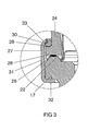
- a ceramic discharge vessel 2 the two-sided is closed, is arranged longitudinally in the lamp axis A. It's tight surrounded by an outer bulb 3, which is squeezed on one side and made of tempered glass or quartz glass is made.
- a frame 4 with short and long supply line 5, 6 holds the discharge vessel 2 in the outer bulb 3.
- the electrodes 7 in the interior of the discharge vessel are connected via bushings 8 with the leads 5, 6.
- the latter are in the region of a pinch 9, which closes the outer bulb 3, connected to external power supply lines 10.
- the pinch 9 of the outer bulb sits over a cavity 11 of a base 12 made of ceramic and is by a Retained holding member 13 made of metal.
- the pedestal can also be from another Be made of material, for example, a heavy-duty plastic.
- the retaining clip 13 protrudes from a plane of the base stone, which is an upper plateau 14 of a radially projecting disk-shaped segment 15 forms.
- the Segment 15 is further provided with a sidewall 16 and a lower plateau 17 executed. It is sitting on a neck part 18, the part assigned to it, here a screw base part 19 threaded, holds.
- the screw base 19 is by means of Crimp 20 attached to the neck portion 18.
- the Power supply lines 10 with electrical connections 21 of the base of the neck portion connected (not visible).
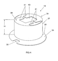
- the holding element 13 is designed in two parts and consists, as shown in detail in the figures 4 and 5, of two joined spring clip elements, namely the main clip 34 and the secondary clip 35 sitting underneath. Both are like a top hat built up. They each have a circumferential brim 36, one at the Inner edge attached side wall 37 and a free end final Lid 38.
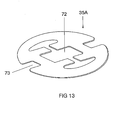
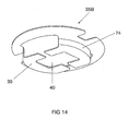
- main clip 34 and slave clip 35 The main difference between main clip 34 and slave clip 35 is the different one Height of the side wall 37. It is in the case of the main clip, in which the Height H of the side wall is typically one to two cm, much larger than in Trap of the secondary clip, in which the height HN of the side wall typically significantly smaller is, and in particular a few mm, about 3 to 6 mm. Under certain circumstances is completely dispensed with the side wall of the side clip. Generally directed the height of the side wall depends on the light center of the in the holding element to be used piston. It may be possible that the Side clip 35A for setting a desired light center no side wall needed, ie a flat disc 71 with corresponding recess 72nd and anti-rotation 73, see Figure 13. At low center of gravity may also require negative values for the height of the sidewall, see Figure 14, i. the side wall 74 extends in the opposite direction, So in the opening 11 of the base stone into it.
- Both elements have a VerFDschutzmechanismus, in the illustrated embodiment in a recess 39, which is roughly rectangular punched in the brim is, is realized. Both elements have this recess the same way twice.
- Both elements see also again Figure 4 and 5, also have an approximately rectangular recess 40 in the lid, the pinch 9 of the outer bulb is adjusted.
- the recess 40 each project four spring tongues 41, the Thus, the I-shaped pinch 9 can fix.
- a part 42 of the side wall, which adjoins the recess can, as shown in Figure 5 for reasons of simplification be distant.
- the enveloping piston 24, see also Fig. 3, is at its opening 25 with a radial projecting edge 27 equipped. He has a flat bottom contact surface 28, which is adapted to the upper plateau 14 of the segment of the base.
- the top Plateau may have bumps 22, which is a spacing of the upper plateau 14 effect to Hüllkolben 24. He also has a narrow upper contact surface 29, which is aligned parallel to the lower contact surface 28 or obliquely thereto. On it sits an elastomeric ring 30, for example made of Viton®.
- Figure 3 shows this area in magnification after a staple part is attached. Shown is a clamp ring made of an aluminum strip 31, the lower edge 32 is angled at about 90 °, so that the band 31 up to the serving as a stop lower plateau 17 of the segment is postponed.
- the stapling effect is achieved in that the upper edge 33, the first aligned straight was subsequently rolled with force, so that he was on the elastomer ring 30 rests.
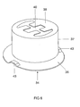
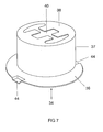
- FIGS. 6 and 7 show another embodiment of a main clip 34. He differs essentially by the differently constructed anti-rotation from the first embodiment. In FIG. 6, it is designed as a bulge 43. In FIG. 7 he designed as a dent 44.
- FIG 8 of the spring clip 13 associated base stone is shown. He fits in with that shown in Figure 7 main clip.
- the base brick 12 has a central opening 11, and a disc-shaped or collar-shaped segment 15 with upper and lower Plateau 14 and 17 and the side wall 16.
- the collar 15 sits on the neck part 18.
- Essential to understanding the anti-rotation is the dent 45, the two opposite sides of the collar is placed in the upper plateau.
- These Delle 45 is similar to the dent 44 in the resilient clip elements, both at main clip 34 and side clip 35. This allows the joined clip elements 34, 35 are also joined to the base brick 12 by each of all three components with aligned dents 44, 45 are arranged.
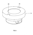
- Fig. 9 shows another embodiment of the base block 12, in which the anti-rotation part a bulge 46 is.
- This bump 46 is either shaped like the same the bulge 43 of the main clip in Figure 6, so that here again a twist is realized, the quasi the positive to the solution shown in Figure 8 means Represents negative.
- the bulge 46 with the correspondingly adapted recesses 39 can interact from Figure 4 and 5.
- the solution has the bumps the advantage that this easily a permanent connection of the resilient Clip elements is possible by main and secondary clip 34, 35, for example connected by laser welding in the region of the two bumps 39 become.
- FIG. 10 shows a reflector lamp 60 with a reflector part 61 as an enveloping part.
- the contour of the reflector part 61 is made of aluminum.
- On the base stone 62 sits a separate collar ring 63 which is cylindrically shaped and the outer bulb 64 partially surrounds, but below the discharge volume 65 of Discharge vessel 66 ends.
- An attachment is realized by crimping. For details, this can be found in DE-Az 103 36 282.7.
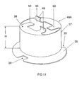
- Fig. 11 shows a holding device, which consists of only one element.
- the spring clip element 48 has the same structure as the main clip in Figure 4.
- the two other spring tongues 50 are in front of the Inserting the piston is still straight, but may already be in advance for support be bent down a bit. It is recommended for better axial alignment as similar pairs of spring tongues always diametrically opposed Use spring tongues.
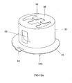
- Main and secondary clip also united in a single spring clip 34A.
- the clip executed in principle as a main clip, with lid 38 as the first holding plane.
- the second holding plane, which is normally formed by the lid of the secondary clip is is now through from the cylindrical portion of the clip, so the side wall 37, punched and spring-bent elements 69 replaced.
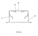
- FIG. 12b is constructed in a manner very similar to FIG. 12a. but it shows a clip 80, in which the resilient elements in contrast to Figure 12a elements 81 of the side wall 83 are again at their free ends are bent over. the spring tongues 82 on the cover are already slightly bent downwards.
- the dimensions of the Clip element suitably matched to each other, especially the diameter
- the cylindrical side walls should be slightly different. It is advisable in particular a slightly conical shape of the side walls, the stackability favored several clip elements.
Landscapes
- Fastening Of Light Sources Or Lamp Holders (AREA)
- Common Detailed Techniques For Electron Tubes Or Discharge Tubes (AREA)
- Non-Portable Lighting Devices Or Systems Thereof (AREA)
- Vessels And Coating Films For Discharge Lamps (AREA)
Abstract
Ein Haltevorrichtung (13) zur Fixierung eines Lampenkolbens besteht aus mindestens
einem Clipelement, wobei das Clipelement, Hauptclip (34) genannt, eine umlaufende
Krempe (36) als Auflagefläche besitzt, an die sich an deren Innenrand eine
umlaufende Seitenwand (37) mit gegebener Höhe H anschließt, die bevorzugt zylindrisch
gestaltet ist, wobei deren freies Ende einen abschließenden Deckel (38)
bildet, wobei der Deckel (38) eine Ausnehmung (40) aufweist, der dem zu fixierenden
Abschnitt (9) des Lampenkolbens angepasst ist.

Description
Die Erfindung betrifft eine Haltevorrichtung zur Fixierung eines Lampenkolbens und zugehörige Lampe gemäß dem Oberbegriff des Anspruchs 1. Es handelt sich dabei insbesondere um Hochdruckentladungslampen, bevorzugt Metallhalogenidlampen, aber auch beispielsweise um Halogenglühlampen. Häufig wird dabei ein längsgestrecktes, insbesondere keramisches, Entladungsgefäß als Lampenkolben benutzt. Details einer derartigen Lampe sind in der noch unveröffentlichten DE-Az 103 36 282.7 offenbart.The invention relates to a holding device for fixing a lamp bulb and associated lamp according to the preamble of claim 1. It is here in particular high-pressure discharge lamps, preferably metal halide lamps, but also, for example, to halogen bulbs. Often an elongated, in particular ceramic, discharge vessel used as a lamp envelope. Details of such a lamp are in the still unpublished DE-Az 103 36 282.7.
Aus der DE-C1 43 17 252 ist bereits eine Haltevorrichtung zur Fixierung eines Lampenkolbens und zugehörige Lampe bekannt, die aus drei Kolben aufgebaut ist. Sie besitzt einen keramischen Adapter, der an einem Schraubsockel montiert ist. Zwischen dem Hüllkolben und Außenkolben herrscht Atmosphärendruck.From DE-C1 43 17 252 is already a holding device for fixing a lamp envelope and associated lamp known, which is composed of three pistons. she has a ceramic adapter, which is mounted on a screw base. Between The outer bulb and outer bulb is at atmospheric pressure.
Die EP 1 109 199 beschreibt eine einseitig gesockelte Hochdrucklampe, bei der der Außenkolben von einem Reflektor umgeben ist. Der Sockel ist mittels einer Crimpung direkt am Reflektorhals befestigt. Nachteilig daran ist, dass die Bemaßung des Halses des Reflektors auf die Standardmaße des Sockels abgestimmt sein muss.EP 1 109 199 describes a single ended high pressure lamp in which the Outer bulb is surrounded by a reflector. The base is by crimping attached directly to the reflector neck. The disadvantage of this is that the dimensioning of the Neck of the reflector must be matched to the standard dimensions of the base.
Es ist Aufgabe der vorliegenden Erfindung, eine einseitig gesockelte Lampe gemäß dem Oberbegriff des Anspruchs 1 bereitzustellen, die einfach zu montieren und gut automatisierbar herzustellen ist. It is an object of the present invention, a single-ended lamp according to to provide the preamble of claim 1, which is easy to assemble and good is to produce automated.
Diese Aufgabe wird durch die kennzeichnenden Merkmale des Anspruchs 1 gelöst. Besonders vorteilhafte Ausgestaltungen finden sich in den abhängigen Ansprüchen.This object is solved by the characterizing features of claim 1. Particularly advantageous embodiments can be found in the dependent claims.
Die Erfindung ermöglicht die Fixierung des Lampenkolbens einer einseitig gequetschten Lampe mittels einer Haltevorrichtung, auch Halteelement genannt, dessen Haltefunktion entweder durch Formschluss oder durch Federkraft realisiert wird. Insbesondere eignet sich dafür ein Federclip, der als Clip-Mechanismus gestaltet ist. Damit ist die Lampe besonders geeignet zur einfachen mechanischen und automatengerechten Fertigung auf Fertigungslinien ohne heiße Prozesse wie beispielsweise Einschmelzen, Schweißen oder Löten. Zudem werden lange Prozesszeiten beispielsweise für Trocknen, Ausheizen oder Pumpen, vermieden. Der Lampenkolben wird kittlos, mittels zweier Clips, vorzugsweise aus Metall oder auch Kunststoff, fixiert.The invention enables the fixation of the lamp bulb of a one-sided crushed Lamp by means of a holding device, also called retaining element whose Holding function is realized either by form fit or by spring force. In particular, it is suitable for a spring clip that is designed as a clip mechanism. Thus, the lamp is particularly suitable for simple mechanical and automatic machine Production on production lines without hot processes such as Melting, welding or soldering. In addition, long process times, for example for drying, heating or pumping, avoided. The lamp bulb is kittlos, by means of two clips, preferably made of metal or plastic, fixed.
Bisher wurden die Stromzuführungen des Lampenkolbens direkt mit den Gestellkomponenten verschweißt. Eine Evakuierung bzw. eine Inertgasfüllung des Außenkolbens zum Schutz der metallischen Gestellteile vor Oxidation ist notwendig.So far, the power supply of the lamp envelope were directly with the frame components welded. An evacuation or an inert gas filling of the outer bulb to protect the metallic frame parts from oxidation is necessary.
Ein Lampenkolben mit mindestens einem Endabschnitt, meist einer Quetschung oder auch Einschmelzung, wird in ein Halteelement, beispielsweise einen Clip-Mechanismus, vorzugsweise aus Metall, eingesetzt und durch Formschluss oder Federkraft gehalten. Das Halteelement besteht aus einem, besonders bevorzugt jedoch aus zwei Elementen. Ein Halteelement aus einem Teil muss geeignet geformt sein mittels aus einer Ebene ragender Bestandteile, um ein Verkippen des Kolbens zu verhindern. Dagegen stehen bei einem Halteelement aus zwei Teilen alle Gestaltungsmöglichkeiten offen, um das Verkippen auf einfache Weise zu verhindern. In diesem Fall wird im folgenden von einem ersten Teil als Hauptclip und einem zweiten Teil als Nebenclip oder Hilfsclip gesprochen.A lamp bulb with at least one end portion, usually a pinch or melting, is in a holding element, such as a clip mechanism, preferably made of metal, used and by positive locking or Spring force held. The holding element consists of one, more preferably however, two elements. A retaining element of a part must be suitably shaped be means of projecting from a plane components to a tilting of the Prevent piston. In contrast, stand at a holding element of two parts All design options open to prevent tilting in a simple way. In this case, the following is from a first part as the main clip and a second part as Nebenclip or auxiliary clip spoken.
Mindestens eines der Clipelemente, nämlich der Hauptclip, ähnelt einem Hut mit einem hochgezogenen Bereich als Seitenwand, vorzugsweise zylindrisch, und einer umlaufenden Krempe, die als Auflagerand dient. In der Krempe ist ein Verdrehschutzmechanismus eingebaut. Insbesondere handelt es sich dabei um Verdrehschutzzonen, die an der Krempe ausgeklinkt oder ausgespart sind. Alternativ können mindestens eine Vertiefung bzw. Delle und/oder Erhöhung bzw. Beule vorgesehen sein. Im Deckel, also dem oberen Abschluss des hochgezogenen Teils ist eine dem Lampenkolben entsprechende Ausnehmung eingebracht, deren Aufnahmegeometrie dem des Endabschnitts angepasst ist. Insbesondere enthält der Deckel Federelemente oder Formschlusselemente als Ränder der Ausnehmung für die Quetschzone des Lampenkolbens.At least one of the clip elements, namely the main clip, resembles a hat with a raised portion as a side wall, preferably cylindrical, and a circumferential brim, which serves as a support edge. In the brim is a twist protection mechanism built-in. In particular, these are anti-twist zones, which are notched or recessed at the brim. Alternatively you can provided at least one depression or dent and / or increase or bulge be. In the lid, so the upper end of the raised part is a the lamp envelope corresponding recess introduced their receiving geometry adapted to the end portion. In particular, the lid includes spring elements or form-locking elements as edges of the recess for the Pinch zone of the lamp bulb.
Auch der zweite, nämlich der Nebenclip, ist typisch ähnlich aufgebaut wie der Hauptclip, jedoch ist seine Seitenwand niedriger.The second, namely the secondary clip, is typically similar to the structure of the Main clip, however, its sidewall is lower.
In Einzelfällen ist es möglich, das der Nebenclip nur aus einer Krempe und dem darin integrierten Deckel besteht, wobei die dem Lampenkolben entsprechende Aufnahmegeometrie für den Endabschnitt des Lampenkolbens erhalten bleibt. Es handelt sich also um einen Clip ohne Seitenwand. Wenn beide Clipelemente eine Seitenwand aufweisen, ist die Höhe der Seitenwand des Nebenclips immer kleiner als die Höhe der Seitenwand des Hauptclips. Normalerweise ist auch der Durchmesser des Nebenclips geringfügig kleiner als der des Hauptclips um besser die beiden Teile fügen zu können. Dies ist der einfachste Weg, um zu erreichen dass die beiden Clipelemente ineinander fügbar sind. Der gefügte Clipmechanismus kann sowohl lösbar als auch unlösbar, z.B. lasergeschweißt, ausgelegt werden. Durch das Fügen der Clipelemente entsteht, bedingt durch die als Auflageflächen dienenden Krempen, ein definierter, paralleler Abstand der Aufnahmeplateaus. Dieser Abstand ist so gewählt, das die Federelemente des Clipmechanismus an der Oberfläche des Endabschnitts, den sie umgeben, aufliegen, meist eine Quetschfläche des zu fügenden Lampenkolbens. Dabei soll für das den äußeren Stromzuführungen des Lampenkolbens nähere Clipelement, nämlich der Nebenclip, ein bestimmter Sicherheitsabstand zu den Stromzuführungen eingehalten werden.In some cases, it is possible that the Nebenclip only from a brim and the It is integrated in the lid, which corresponds to the lamp envelope Recording geometry for the end portion of the lamp envelope is maintained. It So it is a clip without sidewall. If both clip elements one Sidewall, the height of the side wall of the sub clip is always smaller as the height of the side wall of the main clip. Usually also the diameter the minor clip slightly smaller than the main clip to better the to be able to add both parts. This is the easiest way to accomplish that the two clip elements are joined together. The attached clip mechanism can both solvable and insoluble, e.g. laser welded, be designed. By the joining of the clip elements arises, due to the serving as bearing surfaces Brims, a defined, parallel spacing of the reception plateaus. This distance is chosen so that the spring elements of the clip mechanism on the surface of the end portion, which they surround, rest, usually a squish area of the to be joined lamp bulb. It is intended for the external power supply the lamp envelope closer clip element, namely the secondary clip, a specific Safety distance to the power supply lines are maintained.
Die so gefügte Verbindung der beiden Clipelemente wird auf einen isolierenden Aufsatz, vorzugsweise einem keramischen Adapter, aufgesetzt, wobei der Aufsatz über zum Verdrehschutzmechanismus der Clipelemente korrespondierenden Verdrehschutzmittel verfügt. Dabei werden beispielsweise die in den Clipelementen eingebrachten Verdrehschutzzonen über entsprechende Erhebungen bzw. Vertiefungen in die Adapterkeramik eingesetzt.The so-joined connection of the two clip elements is on an insulating Attachment, preferably a ceramic adapter, mounted, the attachment about anti-twist mechanism of the clip elements corresponding anti-rotation means features. Here, for example, in the clip elements introduced Verdrehschutzzonen via corresponding elevations or depressions used in the adapter ceramic.
Bei, beispielsweise, einer Lampe, die als Hüllteil einen Außenkolben oder einen Reflektor einsetzt, besteht das Hüllteil vorzugsweise aus Glas oder im Falle einer Reflektorlampe aus Aluminium, wobei es mit einer Reflektorkontur ausgestattet ist. In, for example, a lamp, the envelope part as an outer bulb or a Reflector uses, the enveloping part is preferably made of glass or in the case of a Reflector lamp made of aluminum, where it is equipped with a reflector contour.
Das Hüllteil liegt auf der Krempe der Clipelemente auf und wird mittels eines Klammerbandes, z. B. Bördelringes, vorzugsweise Aluminium, verdrehsicher mit dem Aufsatz/Adapter verbunden. Die zwischen dem Hüllteil und dem Aufsatz bzw. konkret der Adapterkeramik liegende Krempe der Clipkombination wird durch das Anformen des Bördelrings ebenfalls fixiert.The Hüllteil rests on the brim of the clip elements and is by means of a staple tape, z. B. crimp ring, preferably aluminum, against rotation with the Attachment / adapter connected. The concrete between the Hüllteil and the essay or the adapter ceramic lying brim of the clip combination is formed by the molding the Bördelrings also fixed.
Vorteilhaft wird der Sockel, vorzugsweise aus Metall, durch Verformung auf dem Aufsatz, der als Sockelstein dient, fixiert. Die elektrische Kontaktierung zwischen äußerer Stromzuführung der Lampe und den Sockelkontakten wird bevorzugt durch ein Verlängerungsstück aus einem geeigneten Leitermaterial hergestellt. Die Verbindungen werden durch Verformung oder Klemmung hergestellt.Advantageously, the base, preferably made of metal, by deformation on the Attachment, which serves as a pedestal, fixed. The electrical contact between external power supply of the lamp and the socket contacts is preferred by an extension made of a suitable conductor material. The connections are made by deformation or clamping.
Eine bevorzugte Anwendung ist in einer einseitig gesockelte Lampe, die einen vakuumdicht
abgeschlossenen Lampenkolben besitzt, insbesondere ein längsgestrecktes
Entladungsgefäß, das u.U. noch in einem Außenkolben untergebracht ist,
wobei der Lampenkolben, also das Entladungsgefäß oder auch die Baueinheit Entladungsgefäß
mit Außenkolben, noch von einem Hüllteil umgeben ist. Bevorzugt
handelt es sich um ein keramisches Entladungsgefäß, insbesondere für eine Metallhalogenidlampe,
beispielsweise für Allgemeinbeleuchtungszwecke. Dabei trägt ein
Sockel mit elektrischen Anschlüssen einerseits den Lampenkolben und andererseits
das Hüllteil. Die elektrischen Anschlüsse sind normalerweise mit Stromzuführungen
verbunden, die einen elektrischen Kontakt zu einem Leuchtmittel im Innern des
Lampenkolben herstellen, beispielsweise ist das Leuchtmittel durch Elektroden oder
einem Leuchtkörper einer Glühlampe realisiert. Ohne Beschränkung der Erfindung
können auch Außenelektroden verwendet werden, oder eine elektrodenlose Konfiguration.
Statt eines keramischen Entladungsgefäßes kann auch ein Entladungsgefäß
aus Quarzglas oder Hartglas verwendet werden. Ein Außenkolben ist nicht unbedingt
erforderlich. Dabei wird die Kombination folgender Merkmale eingesetzt, so
dass eine umständliche Gestellmontage und heiße Prozesse wie Einschmelzen,
Ausheizen des Sockelkitts entfallen:
Insbesondere ist das Hüllteil in einer ersten Ausführungsform dadurch befestigt, dass ein Klammerteil die Distanz zwischen dem unteren Plateau des Sockelsteins und mindestens der oberen Kontaktfläche des Randes halternd überbrückt.In particular, the enveloping part is attached in a first embodiment, that a bracket part the distance between the lower plateau of the base stone and at least the upper contact surface of the edge bridged halternd.
In einer zweiten Ausführungsform kann das Hüllteil und das Klammerteil eine Einheit bilden, wobei die Halterung des Hüllteils im oberen Teil des Sockelsteins realisiert wird, beispielsweise durch eine Crimpung.In a second embodiment, the enveloping part and the clamp part may be one unit form, wherein the holder of the Hüllteils realized in the upper part of the base stone is, for example by crimping.
Der Sockel weist neben dem Sockelstein ein übliches, der Fassung zugewandtes Teil auf, beispielsweise einen Schraubsockelansatz oder Bajonettsockelansatz.The base has next to the base stone a usual, facing the socket Part on, for example, a screw base approach or bayonet socket approach.
Erfindungsgemäß ist der Lampenkolben, also beispielsweise der Außenkolben bzw. das Entladungsgefäß im Falle des Fehlens eines Außenkolbens, in der zentralen Öffnung des Sockelsteins mittels eines auf dem Sockelstein angebrachten speziellen Halteelements, insbesondere eines Federclips, gehaltert.According to the lamp bulb, so for example, the outer bulb or the discharge vessel in the absence of an outer bulb, in the central Opening of the base stone by means of a special mounted on the base stone Retaining element, in particular a spring clip, held.
Insbesondere ist der Rand des Hüllteils und das Segment des Sockelsteins mit einem zusammen wirkenden Verdrehschutzmechanismus ausgestattet ist.In particular, the edge of the Hüllteils and the segment of the base stone with a co-acting anti-rotation mechanism is equipped.
Eine einfache, zuverlässige und kostengünstige Lösung für die Halterung des Hüllteils besteht darin, dass das Klammerteil aus über den Umfang verteilten Klammern oder einem umlaufenden Klammerband besteht. Insbesondere ist das Klammerband ein verformbarer Ring, der insbesondere aus Metall oder Kunststoff gefertigt ist, so dass eine sehr einfache Halterung dadurch möglich wird, dass das Klammerband zunächst am unteren Rand bereits abgewinkelt ist, und es auf Anschlag über den Sockelstein bis zum vorspringenden Segment hochgezogen wird. Sobald das Hüllteil aufgesetzt ist, kann der Ring, bevorzugt aus Aluminium, mechanisch am Segment angeformt werden, und so den Rand des Hüllteils fixieren. A simple, reliable and cost-effective solution for holding the Hüllteils is that the clamp part consists of circumferentially distributed brackets or a circulating clamp band. In particular, the staple band a deformable ring made in particular of metal or plastic is so that a very simple mounting is possible by the fact that the staple tape initially angled at the bottom, and it over to stop the base is pulled up to the projecting segment. As soon as that Hüllteil is attached, the ring, preferably made of aluminum, mechanically on Segment formed, and so fix the edge of the Hüllteils.
Bevorzugt ist zwischen Klammerteil und oberer Kontaktfläche des Rands des Hüllteils ein Dämpfungsmittel eingebracht. Es handelt sich insbesondere um eine Art O-Ring, beispielsweise aus einem Elastomer. Damit wird das Material des Hüllteils, vorteilhaft Glass oder Aluminium, während des Anformprozesses vor Beschädigung geschützt. Ein weiterer Vorteil ist, dass dadurch über die Lebensdauer der Lampe die Verbindungskraft zwischen Hüllteil und Segment spielfrei erhalten bleibt. Aufgrund des Dämpfungsrings kann die Spannung des Klammerteils gefahrlos erhöht werden und somit die Verbindung zuverlässiger gestaltet werden.It is preferred between the clamp part and the upper contact surface of the edge of the Hüllteils introduced a damping agent. It is in particular a kind of O-ring, for example, an elastomer. Thus, the material of the Hüllteils, advantageous glass or aluminum, during the Anformprozesses from damage protected. Another advantage is that it over the life of the lamp the connection force between Hüllteil and segment remains free of play. by virtue of the damping ring can increase the tension of the clamp part safely and thus make the connection more reliable.
Üblicherweise sind aus dem Lampenkolben Stromzuführungen herausgeführt, die mit den elektrischen Anschlüssen des Sockels verbunden sind. Eine besonders flexible und zeitsparende Lösung besteht darin, für die Verbindung zwischen den elektrischen Anschlüssen und den Stromzuführungen Klemmverbindungen zu verwenden, wie sie an sich beispielsweise aus der DE-A 199 14 308 bekannt sind.Usually, power supplies are led out of the lamp envelope, the connected to the electrical terminals of the socket. A particularly flexible and time-saving solution is for the connection between the electrical Terminals and the power supply terminals to use terminal connections as they are known per se, for example from DE-A 199 14 308.
Üblicherweise weist der Sockel außerdem ein fassungszugewandtes Teil auf, das zumindest teilweise wie an sich bekannt mittels Crimpung mit dem Sockelstein verbunden ist. Dieses Teil enthält beispielsweise ein übliches Schraubgewinde.Usually, the base also has a barrel-facing portion that at least partially as known per se connected by crimping with the base stone is. For example, this part contains a standard screw thread.
Bei dem Hüllteil kann es sich beispielsweise um ein geschlossenes Teil wie einem weiteren, jedoch nicht vakuumdicht abgeschlossenen, Außenkolben handeln, oder auch um eine Kalotte, die eine Reflektorkontur aufweist.The envelope part may be, for example, a closed part such as a further, but not vacuum-sealed, outer bulb act, or also around a dome, which has a reflector contour.
Eine typische Anwendung ist eine Metallhalogenidlampe, die eine Füllung mit oder ohne Quecksilber-Anteil, ggf. mit inertem Zündgas, vorteilhaft Edelgas, enthält.A typical application is a metal halide lamp that is filled with or without mercury content, possibly with inert ignition gas, preferably noble gas.
Im folgenden soll die Erfindung anhand mehrerer Ausführungsbeispiele näher erläutert werden. Es zeigen:
- Figur 1
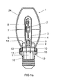
- eine Metallhalogenidlampe in Seitenansicht (Fig. 1a) und in um 90° gedrehter Seitenansicht (Fig. 1b);
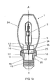
Figur 2- ein zweites Ausführungsbeispiel einer Lampe in Seitenansicht (Fig. 2a) und in um 90° gedrehter Seitenansicht (Fig. 2b);
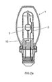
Figur 3- ein Detail der Lampe in Vergrößerung vor endgültiger Befestigung;
Figur 4- eine erste Ausführungsform des Hauptclips;
Figur 5- eine erste Ausführungsform des Nebenclips;
Figur 6- eine zweite Ausführungsform des Hauptclips;
Figur 7- eine dritte Ausführungsform des Hauptclips;
Figur 8- ein erstes Ausführungsbeispiel eines Sockelsteins;
Figur 9- ein zweites Ausführungsbeispiel eines Sockelsteins;
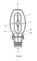
Figur 10- ein Ausführungsbeispiel einer Reflektorlampe;
- Figur 11-14
- weitere Ausführungsbeispiele eines Halteelements.
- FIG. 1
- a metal halide lamp in side view (FIG. 1a) and rotated in 90 ° side view (FIG. 1b);
- FIG. 2
- a second embodiment of a lamp in side view (Fig. 2a) and rotated in 90 ° side view (Fig. 2b);
- FIG. 3
- a detail of the lamp in magnification before final attachment;
- FIG. 4
- a first embodiment of the main clip;
- FIG. 5
- a first embodiment of the secondary clip;
- FIG. 6
- a second embodiment of the main clip;
- FIG. 7
- a third embodiment of the main clip;
- FIG. 8
- a first embodiment of a base stone;
- FIG. 9
- a second embodiment of a base brick;
- FIG. 10
- an embodiment of a reflector lamp;
- Figure 11-14
- further embodiments of a retaining element.
Ein Ausführungsbeispiel einer Metallhalogenidlampe 1 zeigt Fig. 1 und 2, jeweils um
90° gegeneinander gedreht. Ein keramisches Entladungsgefäß 2, das zweiseitig
verschlossen ist, ist längsgestreckt in der Lampenachse A angeordnet. Es ist eng
von einem Außenkolben 3 umgeben, der einseitig gequetscht ist und aus Hartglas
oder Quarzglas gefertigt ist. Ein Gestell 4 mit kurzer und langer Zuleitung 5, 6 haltert
das Entladungsgefäß 2 im Außenkolben 3. Die Elektroden 7 im Innern des Entladungsgefäßes
sind über Durchführungen 8 mit den Zuleitungen 5, 6 verbunden.
Letztere sind im Bereich einer Quetschung 9, die den Außenkolben 3 verschließt,
mit äußeren Stromzuführungen 10 verbunden. Die Quetschung 9 des Außenkolbens
sitzt über einem Hohlraum 11 eines Sockelsteins 12 aus Keramik und ist durch ein
Halteelement 13 aus Metall gehaltert. Der Sockelstein kann auch aus einem anderen
Material gefertigt sein, beispielsweise einem hochbelastbaren Kunststoff.An embodiment of a metal halide lamp 1, Fig. 1 and 2, respectively
90 ° turned against each other. A
Der Halteclip 13 ragt aus einer Ebene des Sockelsteins heraus, die ein oberes Plateau
14 eines radial vorspringenden scheibenförmigen Segments 15 bildet. Das
Segment 15 ist des weiteren mit einer Seitenwand 16 und einem unteren Plateau 17
ausgeführt. Es sitzt auf einem Halsteil 18, das ein fassungszugeordnetes Teil, hier
ein Schraubsockelteil 19 mit Gewinde, haltert. Der Schraubsockel 19 ist mittels
Crimpung 20 am Halsteil 18 befestigt. in der Öffnung 11 des Halsteil 18 sind die
Stromzuführungen 10 mit elektrischen Anschlüssen 21 des Sockels des Halsteils
verbunden (nicht sichtbar). Ähnlich geeignet sind auch andere mechanische Verbindungstechniken
oder eine übliche Schweißverbindung oder eine Klemm-Schneid-Verbindung.The retaining
Das Halteelement 13 ist zweiteilig ausgeführt und besteht, wie im Detail in den Figuren
4 und 5 gezeigt, aus zwei gefügten Federclip-Elementen, nämlich dem Hauptclip
34 und dem darunter sitzenden Nebenclip 35. Beide sind nach Art eines Zylinderhuts
aufgebaut. Sie besitzen jeweils eine umlaufende Krempe 36, eine an deren
Innenrand angesetzte Seitenwand 37 sowie einen deren freies Ende abschließenden
Deckel 38.The holding
Der wesentliche Unterschied zwischen Hauptclip 34 und Nebenclip 35 ist die unterschiedliche
Höhe der Seitenwand 37. Sie ist im Falle des Hauptclips, bei dem die
Höhe H der Seitenwand typisch ein bis zwei cm beträgt, wesentlich größer als im
Falle des Nebenclips, bei dem die Höhe HN der Seitenwand typisch deutlich kleiner
ist, und insbesondere wenige mm, etwa 3 bis 6 mm, beträgt. Unter bestimmten Umständen
wird auf die Seitenwand des Nebenclips gänzlich verzichtet. Generell richtet
sich die Höhe der Seitenwand nach dem einzustellenden Lichtschwerpunkt des
in das Halteelement einzusetzenden Kolbens. Dabei kann es möglich sein, dass der
Nebenclip 35A für das Einstellen eines gewünschten Lichtschwerpunkts keine Seitenwand
benötigt, also eine flache Scheibe 71 mit entsprechender Aussparung 72
und Verdrehschutz 73 darstellt, siehe Figur 13. Bei niedrigem Lichtschwerpunkt
können auch negative Werte für die Höhe der Seitenwand erforderlich sein, siehe
Figur 14, d.h. die Seitenwand 74 erstreckt sich in die entgegengesetzte Richtung,
also in die Öffnung 11 des Sockelsteins hinein.The main difference between
Beide Elemente besitzen einen Verdrehschutzmechanismus, der im gezeigten Ausführungsbeispiel
in einer Aussparung 39, die in etwa rechteckig in der Krempe ausgestanzt
ist, realisiert ist. beide Elemente weisen diese Aussparung gleichartig je
zweimal auf.Both elements have a Verdrehschutzmechanismus, in the illustrated embodiment
in a
Beide Elemente, siehe dazu auch wieder Figur 4 und 5, besitzen ferner eine ungefähr
rechteckige Ausnehmung 40 im Deckel, die der Quetschung 9 des Außenkolbens
angepasst ist. In die Ausnehmung 40 ragen jeweils vier Federzungen 41, die
somit die I-förmig gestaltete Quetschung 9 fixieren können. Ein Teil 42 der Seitenwand,
der an die Ausnehmung anschließt, kann wie in Figur 5 gezeigt aus Vereinfachungsgründen
entfernt sein.Both elements, see also again Figure 4 and 5, also have an approximately
In Figur 2 ist ein weiteres Ausführungsbeispiel einer Lampe gezeigt, deren wesentlicher Unterschied die unterschiedliche Höhe des Deckels des Nebenclips ist. Ein Ausschnitt ist in Fig. 3 gezeigt.In Figure 2, another embodiment of a lamp is shown, the essential Difference is the different height of the lid of the secondary clip. One Detail is shown in Fig. 3.
Ein Hüllkolben 24, der den Außenkolben 3 in relativ großem Abstand umgibt, besitzt
eine sockelseitige Öffnung 25, die kreiszylindrisch ist und im Durchmesser dem Außendurchmesser
des Segments 15 angepasst ist. Zwischen beiden Teilen, die in
Form und Abmessung einander angepasst sind, kann noch ein Pufferteil 26 (gestrichelt
in Fig. 3 eingezeichnet) eingefügt werden, das beispielsweise eine Silikonmanschette
sein kann.An
Der Hüllkolben 24, siehe dazu auch Fig. 3, ist an seiner Öffnung 25 mit einem radial
vorspringenden Rand 27 ausgestattet. Er hat eine ebene untere Kontaktfläche 28,
die dem oberen Plateau 14 des Segments des Sockelsteins angepasst ist. Das obere
Plateau kann Höcker 22 aufweisen, die eine Beabstandung des oberen Plateaus
14 zum Hüllkolben 24 bewirken. Außerdem hat er eine schmale obere Kontaktfläche
29, die parallel zur unteren Kontaktfläche 28 oder auch schräg dazu ausgerichtet ist.
Auf ihr sitzt ein Elastomer-Ring 30, beispielsweise aus Viton®.The enveloping
Figur 3 zeigt diesen Bereich in Vergrößerung, nachdem ein Klammerteil befestigt ist.
Dargestellt ist ein Klammerring aus einem Aluminiumband 31, dessen unterer Rand
32 um etwa 90° abgewinkelt ist, so dass das Band 31 bis zu dem als Anschlag dienenden
unteren Plateau 17 des Segments aufgeschoben ist. Die Klammerwirkung
wird dadurch erzielt, dass der obere Rand 33, der zunächst gerade ausgerichtet
war, nachträglich mit Kraftaufwand angerollt wird, so dass er am Elastomer-Ring 30
aufliegt. Durch die Verbindungskraft wird der Hüllkolben 24 über den Elastomer-Ring
30 mit Spannung, die zur Verformung des Rings 30 führt, gegen die obere
Kontaktfläche 29 des Rands 27 gedrückt.Figure 3 shows this area in magnification after a staple part is attached.
Shown is a clamp ring made of an
In Figur 4 ist der oben erläuterte Hauptclip 34 im Detail gezeigt.In Figure 4, the above-explained
In Figur 5 ist der oben erläuterte Nebenclip 35 im Detail gezeigt.In Figure 5, the above-explained
In Figur 6 und 7 ist ein anderes Ausführungsbeispiel eines Hauptclips 34 gezeigt. Er
unterscheidet sich im wesentlichen durch den anders aufgebauten Verdrehschutz
vom ersten Ausführungsbeispiel. In Figur 6 ist er als Beule 43 gestaltet. In Figur 7 ist
er als Delle 44 gestaltet.FIGS. 6 and 7 show another embodiment of a
In Figur 8 ist der zum Federclip 13 zugehörige Sockelstein gezeigt. Er passt zu dem
in Figur 7 gezeigten Hauptclip. Der Sockelstein 12 besitzt eine zentrale Öffnung 11,
sowie ein scheibenförmiges oder kragenförmiges Segment 15 mit oberem und unterem
Plateau 14 und 17 und der Seitenwand 16. Der Kragen 15 sitzt auf dem Halsteil
18. Wesentlich zum Verständnis des Verdrehschutzes ist die Delle 45, die an zwei
gegenüberliegenden Seiten des Kragens in das obere Plateau eingebracht ist. Diese
Delle 45 ist gleichartig wie die Delle 44 bei den federnden Clipelementen, sowohl
bei Hauptclip 34 als auch Nebenclip 35. Dadurch können die gefügten Clipelemente
34, 35 auch mit dem Sockelstein 12 gefügt werden, indem jeweils alle drei Bauelemente
mit zueinander ausgerichteten Dellen 44, 45 angeordnet werden. Durch das
Einrasten der Delle 44 des Hauptclips und des Nebenclips in die Delle 45 des Sockelsteins
wird ein Drehen relativ zueinander unterbundenIn Figure 8 of the
Fig. 9 zeigt eine weitere Ausführungsform des Sockelsteins 12, bei dem das Verdrehschutzteil
ein Beule 46 ist. Diese Beule 46 ist entweder gleichartig geformt wie
die Beule 43 des Hauptclips in Figur 6, so dass auch hier wieder ein Verdrehschutz
realisiert wird, der quasi das Positiv zu der in Figur 8 dargestellten Lösung mittels
Negativ darstellt. Im Fall der Beule ist aber ein noch einfacherer Verdrehschutz realisierbar,
indem die Beule 46 mit den entsprechend angepassten Aussparungen 39
aus Figur 4 und 5 zusammenwirken kann. Umgekehrt hat die Lösung mit den Beulen
den Vorteil, dass hierdurch leicht eine unlösbare Verbindung der federnden
Clipelemente möglich wird, indem Haupt- und Nebenclip 34, 35 beispielsweise
durch Laserschweißen im Bereich der beiden Beulen 39 miteinander verbunden
werden.Fig. 9 shows another embodiment of the
In Figur 10 ist eine Reflektorlampe 60 gezeigt mit einem Reflektorteil 61 als Hüllteil.
Dabei ist die Kontur des Reflektorteils 61 aus Aluminium gefertigt. Auf dem Sockelstein
62 sitzt ein separater Kragenring 63, der zylindrisch geformt ist und den Außenkolben
64 teilweise umgibt, jedoch unterhalb des Entladungsvolumens 65 des
Entladungsgefäßes 66 endet. Eine Befestigung wird durch Crimpen realisiert. Näheres
hierzu findet sich in DE-Az 103 36 282.7.FIG. 10 shows a
Fig. 11 zeigt eine Haltevorrichtung, die lediglich aus einem Element besteht. Dabei
hat das Federclip-Element 48 den gleichen Aufbau wie der Hauptclip in Figur 4. Der
wesentliche Unterschied ist jedoch, dass die Federzungen anders gebogen sind.
Während in Figur 4 die Federzungen alle beim Einführen der Quetschung des Lampenkolbens
von oben nach unten abgebogen werden und deshalb zur Führung und
Ausrichtung des Lampenkolbens ein zweiter Clip, eben der Nebenclip, mit einem
gewissen Abstand der beiden Deckelebenen nötig ist, genügt dann ein einziger Clip
48, wenn der Lampenkolben kurz ist und wenn jeweils zwei Federzungen 49 von
vorneherein nach oben gebogen sind, so dass sie nicht beim Einführen des Kolbens
nach unten gebogen werden. Die beiden anderen Federzungen 50 sind vor dem
Einführen des Kolbens noch gerade, können aber zur Unterstützung bereits vorab
etwas nach unten gebogen sein. Es empfiehlt sich, zur besseren axialen Ausrichtung
als gleichartige Federzungenpaare immer einander diametral gegenüberliegende
Federzungen zu verwenden.Fig. 11 shows a holding device, which consists of only one element. there
has the spring clip element 48 has the same structure as the main clip in Figure 4. The
The main difference, however, is that the spring tongues are bent differently.
While in Figure 4, the spring tongues all when inserting the pinch of the lamp envelope
be bent from top to bottom and therefore to the leadership and
Orientation of the lamp bulb a second clip, just the secondary clip, with a
certain distance between the two cover levels is necessary, then a single clip is sufficient
48, when the lamp bulb is short and if each two
In einer besonders einfachen Ausführungsform der Figur 12a ist die Funktion von
Haupt- und Nebenclip ebenfalls in einem einzigen Federclip 34A vereint. Hierbei ist
der Clip im Prinzip als Hauptclip ausgeführt, mit Deckel 38 als erster Haltebene. Die
zweite Halteebene, die normalerweise durch den Deckel des Nebenclips gebildet
ist, ist jetzt durch aus dem zylindrischen Teil des Clips, also der Seitenwand 37,
gestanzten und zu Federn gebogenen Elementen 69 ersetzt.In a particularly simple embodiment of FIG. 12a, the function of
Main and secondary clip also united in a
Eine weitere Ausführungsform Figur 12b ist ganz ähnlich wie Figur 12a aufgebaut,
es zeigt aber einen Clip 80, bei dem die federnden Elemente im Unterschied zu Figur
12a Elemente 81 der Seitenwand 83 sind, die an ihren freien Enden nochmals
umgebogen sind. die Federzungen 82 am Deckel sind bereits leicht nach unten vorgebogen.Another embodiment FIG. 12b is constructed in a manner very similar to FIG. 12a.
but it shows a
Ein einziger Clip kann dann alleine verwendet werden, wenn der zu halternde Lampenkolben sehr kurz ist. Trotzdem empfiehlt sich hier die Verwendung eines Mittel zum Verdrehschutz zur Befestigung am Sockelstein, auch wenn keine Fügung mit dem Nebenclip erforderlich ist.A single clip can then be used alone if the bulb to be held is very short. Nevertheless, the use of a remedy is recommended here for torsion protection for attachment to the base stone, even if no joint with the secondary clip is required.
Bei besonders langen Lampenkolben kann zusätzlich zum ersten Nebenclip auch noch ein zweiter Nebenclip verwendet werden.For extra long lamp bulbs in addition to the first auxiliary clip also still a second Nebenclip be used.
In allen Fällen mit mehr als einem Clipelement sind natürlich die Abmessungen der Clipelement geeignet aufeinander abzustimmen, insbesondere der Durchmesser der zylindrischen Seitenwände sollte leicht unterschiedlich sein. Es empfiehlt sich insbesondere eine leicht konische Gestalt der Seitenwände, die die Stapelbarkeit mehrerer Clipelemente begünstigt.In all cases with more than one clip element, of course, the dimensions of the Clip element suitably matched to each other, especially the diameter The cylindrical side walls should be slightly different. It is advisable in particular a slightly conical shape of the side walls, the stackability favored several clip elements.
Claims (14)
Applications Claiming Priority (2)
| Application Number | Priority Date | Filing Date | Title |
|---|---|---|---|
| DE10358361A DE10358361A1 (en) | 2003-12-12 | 2003-12-12 | Holding device for fixing a lamp bulb and associated lamp |
| DE10358361 | 2003-12-12 |
Publications (3)
| Publication Number | Publication Date |
|---|---|
| EP1542256A2 true EP1542256A2 (en) | 2005-06-15 |
| EP1542256A3 EP1542256A3 (en) | 2010-02-17 |
| EP1542256B1 EP1542256B1 (en) | 2013-02-13 |
Family
ID=34485356
Family Applications (1)
| Application Number | Title | Priority Date | Filing Date |
|---|---|---|---|
| EP04028444A Expired - Lifetime EP1542256B1 (en) | 2003-12-12 | 2004-12-01 | Holding device for fixing a lamp envelope and lamp provided with the holding means |
Country Status (6)
| Country | Link |
|---|---|
| US (1) | US7550908B2 (en) |
| EP (1) | EP1542256B1 (en) |
| JP (1) | JP4772319B2 (en) |
| CN (1) | CN100449884C (en) |
| CA (1) | CA2489750A1 (en) |
| DE (1) | DE10358361A1 (en) |
Cited By (3)
| Publication number | Priority date | Publication date | Assignee | Title |
|---|---|---|---|---|
| WO2007099124A1 (en) * | 2006-03-02 | 2007-09-07 | Osram Gesellschaft mit beschränkter Haftung | Lamp with a built-in lamp |
| EP2339609A1 (en) * | 2009-12-22 | 2011-06-29 | Osram Gesellschaft mit Beschränkter Haftung | High pressure discharge lamp |
| EP2020676A3 (en) * | 2007-07-30 | 2012-04-11 | Osram Gesellschaft mit beschränkter Haftung | Electric lamp with an outer vessel and a built-in lamp and method for production of same |
Families Citing this family (19)
| Publication number | Priority date | Publication date | Assignee | Title |
|---|---|---|---|---|
| DE102005005264A1 (en) * | 2005-02-04 | 2006-08-10 | Patent-Treuhand-Gesellschaft für elektrische Glühlampen mbH | Single ended lamp |
| JP4130829B2 (en) * | 2005-08-23 | 2008-08-06 | 松下電器産業株式会社 | Metal vapor discharge lamp and lighting device having the metal vapor discharge lamp |
| JP4547331B2 (en) * | 2005-12-28 | 2010-09-22 | パナソニック株式会社 | Lighting device and metal vapor discharge lamp |
| JP4682048B2 (en) * | 2006-02-01 | 2011-05-11 | パナソニック株式会社 | Metal vapor discharge lamp |
| JP4130842B2 (en) * | 2006-05-31 | 2008-08-06 | 松下電器産業株式会社 | Metal vapor discharge lamp and lighting device |
| CN101454865B (en) * | 2006-05-31 | 2010-12-01 | 松下电器产业株式会社 | Metal vapor discharge lamp and lighting device |
| JP2008210699A (en) * | 2007-02-27 | 2008-09-11 | Osram Melco Toshiba Lighting Kk | High pressure discharge lamp and lighting fixture |
| JP5371787B2 (en) * | 2007-03-12 | 2013-12-18 | コーニンクレッカ フィリップス エヌ ヴェ | High pressure discharge lamp |
| DE102007053564A1 (en) * | 2007-11-09 | 2009-05-14 | Osram Gesellschaft mit beschränkter Haftung | Electric lamp with an outer bulb and a built-in lamp |
| WO2009107060A1 (en) * | 2008-02-29 | 2009-09-03 | Koninklijke Philips Electronics N.V. | A lamp cap and method of manufacturing thereof. |
| DE202008007575U1 (en) * | 2008-06-06 | 2008-08-21 | Osram Gesellschaft mit beschränkter Haftung | Single ended lamp |
| JP2010056031A (en) * | 2008-08-29 | 2010-03-11 | Osram Melco Toshiba Lighting Kk | High-pressure discharge lamp and lighting device |
| GB2477994A (en) | 2010-02-23 | 2011-08-24 | Ecolumens Ltd | Liquid cooled semiconductor light |
| JP2011238398A (en) * | 2010-05-07 | 2011-11-24 | Osram Melco Toshiba Lighting Kk | Bulb and lighting device |
| JP4872008B2 (en) * | 2010-05-07 | 2012-02-08 | パナソニック株式会社 | Lighting device and metal vapor discharge lamp |
| RU2444814C1 (en) * | 2011-03-29 | 2012-03-10 | Юрий Феликсович Верниковский | Thermoelectric cluster, method of its operation, device to connect active element in it with heat power line, generator (versions) and heat pump (versions) on its basis |
| EP2847778A1 (en) * | 2012-05-07 | 2015-03-18 | Koninklijke Philips N.V. | Electric lamp and assembling method therefore |
| US11028989B2 (en) | 2019-11-13 | 2021-06-08 | James M. Aparo | Vehicle headlight device having an ejectable and replaceable lightbulb assembly |
| US11046235B2 (en) | 2019-11-13 | 2021-06-29 | James M. Aparo | Vehicle headlight assembly having an ejectable and replaceable lightbulb |
Family Cites Families (25)
| Publication number | Priority date | Publication date | Assignee | Title |
|---|---|---|---|---|
| JPS59136150A (en) * | 1983-01-27 | 1984-08-04 | Dowa Mining Co Ltd | Flotation method of metallic salt precipitate and gypsum |
| US4623958A (en) * | 1985-01-15 | 1986-11-18 | Gte Products Corporation | Replaceable automobile headlight lamp unit |
| DE3837511A1 (en) * | 1988-11-04 | 1990-05-10 | Philips Patentverwaltung | MOTOR VEHICLE HEADLAMP LAMP AND METHOD FOR THEIR PRODUCTION |
| US5172026A (en) * | 1990-05-21 | 1992-12-15 | Hall Rolland B | Plug in lamp |
| US5465025A (en) * | 1993-05-10 | 1995-11-07 | Litetronics International, Inc. | Lamp with removable base and replaceable bulb capsule |
| DE4317252C1 (en) | 1993-05-24 | 1994-05-05 | Blv Licht & Vakuumtechnik | Gas discharge lamp - has breakage protection provided by grid incorporated in transparent envelope enclosing discharge vessel |
| JPH07320522A (en) * | 1994-05-24 | 1995-12-08 | Yuhshin Co Ltd | Bulb support |
| DE4428357A1 (en) * | 1994-08-10 | 1996-02-15 | Patent Treuhand Ges Fuer Elektrische Gluehlampen Mbh | Halogen light bulb with no cement |
| US5818154A (en) * | 1994-08-10 | 1998-10-06 | Patent-Treuhand-Gesellschaft Fur Elektrische Gluhlampen Mbh | Halogen incandescent lamp in cementless base |
| DE4434124A1 (en) * | 1994-09-23 | 1996-03-28 | Walter Holzer | Clip=on reflector for compact fluorescent lamp |
| US5711596A (en) * | 1995-08-28 | 1998-01-27 | Osram Sylvania Inc. | Mechanical electrical connector for an electric lamp |
| EP0895648B1 (en) * | 1996-09-11 | 2002-03-20 | Koninklijke Philips Electronics N.V. | Reflector lamp |
| DE19709928A1 (en) * | 1997-03-11 | 1998-09-17 | Patent Treuhand Ges Fuer Elektrische Gluehlampen Mbh | Halogen light bulb and socket |
| JPH11260319A (en) * | 1998-03-09 | 1999-09-24 | Ichikoh Ind Ltd | Valve with cap |
| EP0959529B1 (en) | 1998-05-22 | 2005-07-06 | Phoenix Contact GmbH & Co. KG | Electrical connecting unit |
| DE19843506A1 (en) * | 1998-09-23 | 2000-03-30 | Patent Treuhand Ges Fuer Elektrische Gluehlampen Mbh | Electric lamp |
| DE19856871A1 (en) * | 1998-12-09 | 2000-06-15 | Patent Treuhand Ges Fuer Elektrische Gluehlampen Mbh | Bulb-free lamp |
| DE19951203A1 (en) * | 1999-10-22 | 2001-04-26 | Patent Treuhand Ges Fuer Elektrische Gluehlampen Mbh | Headlamp bulb for vehicle has metal base part with base flange, reference noses parallel to flange and clips perpendicular to flange that co-operate with reference noses to fix bulb in headlamp |
| DE10210856A1 (en) * | 2001-07-06 | 2003-01-16 | Philips Corp Intellectual Pty | Lamp, in particular for motor vehicle headlights |
| KR100905726B1 (en) * | 2001-07-06 | 2009-07-01 | 코닌클리즈케 필립스 일렉트로닉스 엔.브이. | Lamps, lamp manufacturing methods and continuum of lamps |
| DE10260125A1 (en) * | 2002-12-19 | 2004-07-01 | Patent-Treuhand-Gesellschaft für elektrische Glühlampen mbH | lighting unit |
| US7002285B2 (en) * | 2003-01-03 | 2006-02-21 | General Electric Company | Discharge lamp with bulb fixture arrangement and method for manufacturing the same |
| DE10312806A1 (en) * | 2003-03-21 | 2004-09-30 | Patent-Treuhand-Gesellschaft für elektrische Glühlampen mbH | lamp |
| DE10336282A1 (en) | 2003-08-07 | 2005-02-17 | Patent-Treuhand-Gesellschaft für elektrische Glühlampen mbH | Single ended lamp |
| TWI363365B (en) * | 2003-10-03 | 2012-05-01 | Koninkl Philips Electronics Nv | Discharge lamp |
-
2003
- 2003-12-12 DE DE10358361A patent/DE10358361A1/en not_active Withdrawn
-
2004
- 2004-12-01 EP EP04028444A patent/EP1542256B1/en not_active Expired - Lifetime
- 2004-12-09 JP JP2004357044A patent/JP4772319B2/en not_active Expired - Fee Related
- 2004-12-10 CA CA002489750A patent/CA2489750A1/en not_active Abandoned
- 2004-12-13 CN CNB2004100758913A patent/CN100449884C/en not_active Expired - Fee Related
- 2004-12-13 US US11/009,032 patent/US7550908B2/en not_active Expired - Fee Related
Cited By (4)
| Publication number | Priority date | Publication date | Assignee | Title |
|---|---|---|---|---|
| WO2007099124A1 (en) * | 2006-03-02 | 2007-09-07 | Osram Gesellschaft mit beschränkter Haftung | Lamp with a built-in lamp |
| US8079741B2 (en) | 2006-03-02 | 2011-12-20 | Osram Ag | Lamp with a built-in lamp |
| EP2020676A3 (en) * | 2007-07-30 | 2012-04-11 | Osram Gesellschaft mit beschränkter Haftung | Electric lamp with an outer vessel and a built-in lamp and method for production of same |
| EP2339609A1 (en) * | 2009-12-22 | 2011-06-29 | Osram Gesellschaft mit Beschränkter Haftung | High pressure discharge lamp |
Also Published As
| Publication number | Publication date |
|---|---|
| US20050127807A1 (en) | 2005-06-16 |
| JP2005174936A (en) | 2005-06-30 |
| DE10358361A1 (en) | 2005-07-07 |
| CN1655410A (en) | 2005-08-17 |
| EP1542256B1 (en) | 2013-02-13 |
| JP4772319B2 (en) | 2011-09-14 |
| EP1542256A3 (en) | 2010-02-17 |
| CN100449884C (en) | 2009-01-07 |
| CA2489750A1 (en) | 2005-06-12 |
| US7550908B2 (en) | 2009-06-23 |
Similar Documents
| Publication | Publication Date | Title |
|---|---|---|
| EP1542256B1 (en) | Holding device for fixing a lamp envelope and lamp provided with the holding means | |
| EP0839381B1 (en) | Reflector lamp | |
| DE10336282A1 (en) | Single ended lamp | |
| EP0451647B1 (en) | High-pressure discharge lamp and method for its manufacture | |
| DE60021218T2 (en) | Arc tube, mounting element and electric lamp assembly | |
| DE19856871A1 (en) | Bulb-free lamp | |
| WO2010124904A1 (en) | Discharge lamp | |
| WO2009156251A2 (en) | Electrical lamp comprising an outer bulb and an integrated lamp | |
| EP2131382B1 (en) | Single socket lamp | |
| DE19722601A1 (en) | Electric lamp system e.g. for metal halide arc discharge lamp | |
| DE4425151A1 (en) | Lamp body, which can be focused, in a cement-free cap | |
| WO2006081806A2 (en) | Lamp with a holder on one side | |
| DE19918980A1 (en) | Parabolic lamp arrangement, especially of parabolic aluminized reflector type | |
| DE202004012293U1 (en) | Single ended lamp | |
| EP1329931B1 (en) | Compact low pressure discharge lamp | |
| EP2009668B1 (en) | Discharge lamp socketed on one side | |
| WO2010069681A1 (en) | Electrical lamp having an outer bulb and a built-in lamp | |
| WO2009049661A1 (en) | High-pressure discharge lamp | |
| EP1659617A1 (en) | Light source | |
| EP2458614B1 (en) | Electric lamp with an outer bulb and a fitted lamp | |
| WO2010127705A1 (en) | Electric lamp having an outer bulb and an installed lamp | |
| EP1274112B1 (en) | Socket assembly for an electric lamp | |
| EP3279920A1 (en) | Centering element and fixing means for electrical lighting means | |
| DE102004056004A1 (en) | High pressure discharge lamp | |
| DE10325553A1 (en) | Lamp closed on both sides |
Legal Events
| Date | Code | Title | Description |
|---|---|---|---|
| PUAI | Public reference made under article 153(3) epc to a published international application that has entered the european phase |
Free format text: ORIGINAL CODE: 0009012 |
|
| AK | Designated contracting states |
Kind code of ref document: A2 Designated state(s): AT BE BG CH CY CZ DE DK EE ES FI FR GB GR HU IE IS IT LI LT LU MC NL PL PT RO SE SI SK TR |
|
| AX | Request for extension of the european patent |
Extension state: AL BA HR LV MK YU |
|
| PUAL | Search report despatched |
Free format text: ORIGINAL CODE: 0009013 |
|
| AK | Designated contracting states |
Kind code of ref document: A3 Designated state(s): AT BE BG CH CY CZ DE DK EE ES FI FR GB GR HU IE IS IT LI LT LU MC NL PL PT RO SE SI SK TR |
|
| AX | Request for extension of the european patent |
Extension state: AL BA HR LV MK YU |
|
| 17P | Request for examination filed |
Effective date: 20100521 |
|
| 17Q | First examination report despatched |
Effective date: 20100615 |
|
| AKX | Designation fees paid |
Designated state(s): AT BE BG CH CY CZ DE DK EE ES FI FR GB GR HU IE IS IT LI LT LU MC NL PL PT RO SE SI SK TR |
|
| RAP1 | Party data changed (applicant data changed or rights of an application transferred) |
Owner name: OSRAM GESELLSCHAFT MIT BESCHRAENKTER HAFTUNG |
|
| GRAP | Despatch of communication of intention to grant a patent |
Free format text: ORIGINAL CODE: EPIDOSNIGR1 |
|
| RAP1 | Party data changed (applicant data changed or rights of an application transferred) |
Owner name: OSRAM AG |
|
| GRAS | Grant fee paid |
Free format text: ORIGINAL CODE: EPIDOSNIGR3 |
|
| GRAA | (expected) grant |
Free format text: ORIGINAL CODE: 0009210 |
|
| AK | Designated contracting states |
Kind code of ref document: B1 Designated state(s): AT BE BG CH CY CZ DE DK EE ES FI FR GB GR HU IE IS IT LI LT LU MC NL PL PT RO SE SI SK TR |
|
| REG | Reference to a national code |
Ref country code: GB Ref legal event code: FG4D Free format text: NOT ENGLISH |
|
| REG | Reference to a national code |
Ref country code: AT Ref legal event code: REF Ref document number: 596874 Country of ref document: AT Kind code of ref document: T Effective date: 20130215 |
|
| RAP2 | Party data changed (patent owner data changed or rights of a patent transferred) |
Owner name: OSRAM GMBH |
|
| REG | Reference to a national code |
Ref country code: IE Ref legal event code: FG4D Free format text: LANGUAGE OF EP DOCUMENT: GERMAN |
|
| REG | Reference to a national code |
Ref country code: DE Ref legal event code: R096 Ref document number: 502004014016 Country of ref document: DE Effective date: 20130411 |
|
| REG | Reference to a national code |
Ref country code: AT Ref legal event code: HC Ref document number: 596874 Country of ref document: AT Kind code of ref document: T Owner name: OSRAM GMBH, DE Effective date: 20130221 |
|
| RAP2 | Party data changed (patent owner data changed or rights of a patent transferred) |
Owner name: OSRAM GMBH |
|
| REG | Reference to a national code |
Ref country code: NL Ref legal event code: VDEP Effective date: 20130213 |
|
| REG | Reference to a national code |
Ref country code: LT Ref legal event code: MG4D Effective date: 20121209 |
|
| PG25 | Lapsed in a contracting state [announced via postgrant information from national office to epo] |
Ref country code: LT Free format text: LAPSE BECAUSE OF FAILURE TO SUBMIT A TRANSLATION OF THE DESCRIPTION OR TO PAY THE FEE WITHIN THE PRESCRIBED TIME-LIMIT Effective date: 20130213 Ref country code: IS Free format text: LAPSE BECAUSE OF FAILURE TO SUBMIT A TRANSLATION OF THE DESCRIPTION OR TO PAY THE FEE WITHIN THE PRESCRIBED TIME-LIMIT Effective date: 20130613 Ref country code: BG Free format text: LAPSE BECAUSE OF FAILURE TO SUBMIT A TRANSLATION OF THE DESCRIPTION OR TO PAY THE FEE WITHIN THE PRESCRIBED TIME-LIMIT Effective date: 20130513 Ref country code: ES Free format text: LAPSE BECAUSE OF FAILURE TO SUBMIT A TRANSLATION OF THE DESCRIPTION OR TO PAY THE FEE WITHIN THE PRESCRIBED TIME-LIMIT Effective date: 20130524 Ref country code: CY Free format text: LAPSE BECAUSE OF FAILURE TO SUBMIT A TRANSLATION OF THE DESCRIPTION OR TO PAY THE FEE WITHIN THE PRESCRIBED TIME-LIMIT Effective date: 20130213 Ref country code: SE Free format text: LAPSE BECAUSE OF FAILURE TO SUBMIT A TRANSLATION OF THE DESCRIPTION OR TO PAY THE FEE WITHIN THE PRESCRIBED TIME-LIMIT Effective date: 20130213 |
|
| PG25 | Lapsed in a contracting state [announced via postgrant information from national office to epo] |
Ref country code: SI Free format text: LAPSE BECAUSE OF FAILURE TO SUBMIT A TRANSLATION OF THE DESCRIPTION OR TO PAY THE FEE WITHIN THE PRESCRIBED TIME-LIMIT Effective date: 20130213 Ref country code: PL Free format text: LAPSE BECAUSE OF FAILURE TO SUBMIT A TRANSLATION OF THE DESCRIPTION OR TO PAY THE FEE WITHIN THE PRESCRIBED TIME-LIMIT Effective date: 20130213 Ref country code: PT Free format text: LAPSE BECAUSE OF FAILURE TO SUBMIT A TRANSLATION OF THE DESCRIPTION OR TO PAY THE FEE WITHIN THE PRESCRIBED TIME-LIMIT Effective date: 20130613 Ref country code: FI Free format text: LAPSE BECAUSE OF FAILURE TO SUBMIT A TRANSLATION OF THE DESCRIPTION OR TO PAY THE FEE WITHIN THE PRESCRIBED TIME-LIMIT Effective date: 20130213 Ref country code: GR Free format text: LAPSE BECAUSE OF FAILURE TO SUBMIT A TRANSLATION OF THE DESCRIPTION OR TO PAY THE FEE WITHIN THE PRESCRIBED TIME-LIMIT Effective date: 20130514 |
|
| PG25 | Lapsed in a contracting state [announced via postgrant information from national office to epo] |
Ref country code: SK Free format text: LAPSE BECAUSE OF FAILURE TO SUBMIT A TRANSLATION OF THE DESCRIPTION OR TO PAY THE FEE WITHIN THE PRESCRIBED TIME-LIMIT Effective date: 20130213 Ref country code: CZ Free format text: LAPSE BECAUSE OF FAILURE TO SUBMIT A TRANSLATION OF THE DESCRIPTION OR TO PAY THE FEE WITHIN THE PRESCRIBED TIME-LIMIT Effective date: 20130213 Ref country code: EE Free format text: LAPSE BECAUSE OF FAILURE TO SUBMIT A TRANSLATION OF THE DESCRIPTION OR TO PAY THE FEE WITHIN THE PRESCRIBED TIME-LIMIT Effective date: 20130213 Ref country code: NL Free format text: LAPSE BECAUSE OF FAILURE TO SUBMIT A TRANSLATION OF THE DESCRIPTION OR TO PAY THE FEE WITHIN THE PRESCRIBED TIME-LIMIT Effective date: 20130213 Ref country code: RO Free format text: LAPSE BECAUSE OF FAILURE TO SUBMIT A TRANSLATION OF THE DESCRIPTION OR TO PAY THE FEE WITHIN THE PRESCRIBED TIME-LIMIT Effective date: 20130213 Ref country code: DK Free format text: LAPSE BECAUSE OF FAILURE TO SUBMIT A TRANSLATION OF THE DESCRIPTION OR TO PAY THE FEE WITHIN THE PRESCRIBED TIME-LIMIT Effective date: 20130213 |
|
| REG | Reference to a national code |
Ref country code: DE Ref legal event code: R081 Ref document number: 502004014016 Country of ref document: DE Owner name: OSRAM GMBH, DE Free format text: FORMER OWNER: OSRAM GMBH, 81543 MUENCHEN, DE Effective date: 20130909 Ref country code: DE Ref legal event code: R081 Ref document number: 502004014016 Country of ref document: DE Owner name: OSRAM GMBH, DE Free format text: FORMER OWNER: PATENT-TREUHAND-GESELLSCHAFT FUER ELEKTRISCHE GLUEHLAMPEN MBH, 81543 MUENCHEN, DE Effective date: 20130213 |
|
| PLBE | No opposition filed within time limit |
Free format text: ORIGINAL CODE: 0009261 |
|
| STAA | Information on the status of an ep patent application or granted ep patent |
Free format text: STATUS: NO OPPOSITION FILED WITHIN TIME LIMIT |
|
| PG25 | Lapsed in a contracting state [announced via postgrant information from national office to epo] |
Ref country code: IT Free format text: LAPSE BECAUSE OF FAILURE TO SUBMIT A TRANSLATION OF THE DESCRIPTION OR TO PAY THE FEE WITHIN THE PRESCRIBED TIME-LIMIT Effective date: 20130213 |
|
| 26N | No opposition filed |
Effective date: 20131114 |
|
| REG | Reference to a national code |
Ref country code: DE Ref legal event code: R097 Ref document number: 502004014016 Country of ref document: DE Effective date: 20131114 |
|
| BERE | Be: lapsed |
Owner name: OSRAM A.G. Effective date: 20131231 |
|
| REG | Reference to a national code |
Ref country code: DE Ref legal event code: R119 Ref document number: 502004014016 Country of ref document: DE |
|
| REG | Reference to a national code |
Ref country code: CH Ref legal event code: PL |
|
| GBPC | Gb: european patent ceased through non-payment of renewal fee |
Effective date: 20131201 |
|
| PG25 | Lapsed in a contracting state [announced via postgrant information from national office to epo] |
Ref country code: MC Free format text: LAPSE BECAUSE OF FAILURE TO SUBMIT A TRANSLATION OF THE DESCRIPTION OR TO PAY THE FEE WITHIN THE PRESCRIBED TIME-LIMIT Effective date: 20130213 Ref country code: LU Free format text: LAPSE BECAUSE OF FAILURE TO SUBMIT A TRANSLATION OF THE DESCRIPTION OR TO PAY THE FEE WITHIN THE PRESCRIBED TIME-LIMIT Effective date: 20131201 |
|
| REG | Reference to a national code |
Ref country code: IE Ref legal event code: MM4A |
|
| REG | Reference to a national code |
Ref country code: DE Ref legal event code: R119 Ref document number: 502004014016 Country of ref document: DE Effective date: 20140701 |
|
| REG | Reference to a national code |
Ref country code: FR Ref legal event code: ST Effective date: 20140829 |
|
| PG25 | Lapsed in a contracting state [announced via postgrant information from national office to epo] |
Ref country code: LI Free format text: LAPSE BECAUSE OF NON-PAYMENT OF DUE FEES Effective date: 20131231 Ref country code: CH Free format text: LAPSE BECAUSE OF NON-PAYMENT OF DUE FEES Effective date: 20131231 Ref country code: DE Free format text: LAPSE BECAUSE OF NON-PAYMENT OF DUE FEES Effective date: 20140701 Ref country code: BE Free format text: LAPSE BECAUSE OF NON-PAYMENT OF DUE FEES Effective date: 20131231 Ref country code: IE Free format text: LAPSE BECAUSE OF NON-PAYMENT OF DUE FEES Effective date: 20131201 |
|
| PG25 | Lapsed in a contracting state [announced via postgrant information from national office to epo] |
Ref country code: FR Free format text: LAPSE BECAUSE OF NON-PAYMENT OF DUE FEES Effective date: 20131231 Ref country code: GB Free format text: LAPSE BECAUSE OF NON-PAYMENT OF DUE FEES Effective date: 20131201 |
|
| REG | Reference to a national code |
Ref country code: AT Ref legal event code: MM01 Ref document number: 596874 Country of ref document: AT Kind code of ref document: T Effective date: 20131201 |
|
| PG25 | Lapsed in a contracting state [announced via postgrant information from national office to epo] |
Ref country code: AT Free format text: LAPSE BECAUSE OF NON-PAYMENT OF DUE FEES Effective date: 20131201 |
|
| PG25 | Lapsed in a contracting state [announced via postgrant information from national office to epo] |
Ref country code: TR Free format text: LAPSE BECAUSE OF FAILURE TO SUBMIT A TRANSLATION OF THE DESCRIPTION OR TO PAY THE FEE WITHIN THE PRESCRIBED TIME-LIMIT Effective date: 20130213 |
|
| PG25 | Lapsed in a contracting state [announced via postgrant information from national office to epo] |
Ref country code: HU Free format text: LAPSE BECAUSE OF FAILURE TO SUBMIT A TRANSLATION OF THE DESCRIPTION OR TO PAY THE FEE WITHIN THE PRESCRIBED TIME-LIMIT; INVALID AB INITIO Effective date: 20041201 |