EP1541736A2 - Verriegelungsvorrichtung für eine Unterfadenspule - Google Patents
Verriegelungsvorrichtung für eine Unterfadenspule Download PDFInfo
- Publication number
- EP1541736A2 EP1541736A2 EP04405582A EP04405582A EP1541736A2 EP 1541736 A2 EP1541736 A2 EP 1541736A2 EP 04405582 A EP04405582 A EP 04405582A EP 04405582 A EP04405582 A EP 04405582A EP 1541736 A2 EP1541736 A2 EP 1541736A2
- Authority
- EP
- European Patent Office
- Prior art keywords
- bobbin
- locking element
- coil
- locking device
- locking
- Prior art date
- Legal status (The legal status is an assumption and is not a legal conclusion. Google has not performed a legal analysis and makes no representation as to the accuracy of the status listed.)
- Granted
Links
- 238000009958 sewing Methods 0.000 claims abstract description 7
- 238000004804 winding Methods 0.000 claims 1
- 239000002775 capsule Substances 0.000 abstract 2
- 239000011800 void material Substances 0.000 abstract 1
- 230000004323 axial length Effects 0.000 description 2
- 230000001419 dependent effect Effects 0.000 description 1
- 238000006073 displacement reaction Methods 0.000 description 1
- 230000001771 impaired effect Effects 0.000 description 1
- 238000003780 insertion Methods 0.000 description 1
- 230000037431 insertion Effects 0.000 description 1
- 238000000034 method Methods 0.000 description 1
Images


Classifications
-
- D—TEXTILES; PAPER
- D05—SEWING; EMBROIDERING; TUFTING
- D05B—SEWING
- D05B57/00—Loop takers, e.g. loopers
- D05B57/26—Bobbin holders or casings; Bobbin holder or case guards; Bobbin discharge devices
Definitions
- the invention relates to a locking device for a bobbin according to the preamble of Patent claim 1.
- the bobbin of sewing machines can either be stored directly in the bobbin and is thus directly accessible or it can be inserted in a specially designed bobbin case, which in turn is mounted in the bobbin.
- the present invention relates to a bobbin mounted directly in the bobbin; However, it can also be used for a coil mounted indirectly in a bobbin case.
- a bobbin case for rotary gripper is known, in which the coil on a cylindrical bobbin, which is part of the bobbin case, pushed and held by a safety lever.
- the safety lever designed as a two-armed lever, is held in the two positions (open position and working position) by a spring-loaded plate.
- the locking is released by manually turning the lever by 90 ° into an axially parallel position. Thereafter, the coil can be lifted out of the bobbin.
- a coil spring between the coil base, ie the underlying coil flange, and the bobbin. This pushes after release of the coil by the lever, the coil partially out of the bobbin.
- the spring exerts during braking a braking torque on the coil, which varies depending on the design of the coil surface and can not be influenced. This can hinder the sewing process.
- a spool holder in which the spool is held by a spring-loaded retaining mandrel passing through the spool.
- the retaining pin can be brought by a quarter turn out of the holding in the removal position and dissolves completely together with the coil from the bobbin. The retaining pin must therefore be inserted into this when inserting a full bobbin and then secured.
- An object of the present invention is the creation a locking device for a bobbin, held with the lower thread bobbin in the bobbin can be without uncontrollable braking forces on they act, and in addition an axial pushing out the coil or the bobbin case from the bobbin the unlocking causes.
- the Holding position which caught the coil in the bobbin holds, dissolved and at the same time the partial ejection of the Coil can be initiated.
- the locking of a new in the bobbin to be inserted coil is done by axial insertion of the coil in the bobbin, until these in the recess in the bobbin abuts. There are then no further interlocking actions necessary.
- the held by the locking element coil is through Braking the locking element in no way, because the latter does not touch the coil frictionally.
- the only two-part locking element is captive connected to the bobbin and remains even after removing the coil on the bobbin.
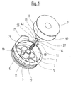
- reference numeral 1 denotes a coil carrier for a coil 3.
- the coil 3 may have flanges with or without weight-reducing holes.
- the bobbin 1 comprises a bottom 5, which may be broken to reduce the mass of holes 7.
- a hollow cylindrical spool 9 is formed with a central bore 10.
- the bottom 5 In the shell of which two opposing and axially extending slots 11 and 13 are embedded.
- the bottom 5 In the area of the slots 11, 13, the bottom 5 may be partially broken, so that recesses 15, 17 are formed.
- the two recesses 15,17 are not connected to each other, but they are separated by a web 19 (Fig.2).
- the web 19 is part of the bottom 5.
- the axial extent of the first slot 11 is greater than the axial extent of the second slot 13, so that the upper ends 43,45 of the slots 11 and 13 do not have the same distance from the bottom 5 (see in particular Figure 2).
- the two slots 11,13 form an anti-rotation and an axial stop for a locking element 21, which is biased by a coil spring, short spring 23.
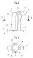
- the locking element 21 comprises two legs 25,27, on each of which an outwardly projecting foot 29,31 is formed.
- the two legs 25,27 are spaced from each other in the substantially cylindrical lateral surface 22 of the locking element 21 and are connected to the feet 29,31 opposite ends with a handle plate 33.
- the two legs 25,27 are produced by a slotted cylinder (see Figure 6).
- a blind bore 32 in the locking element 21 forms a guide for the spring 23.
- the handle plate 33 projects beyond the first leg 25 radially.
- the outer surface 35 of the second leg 27 is flush with the rear edge 37 of the handle plate 33.
- Below the first leg 25 projecting nose 39 is spaced from the lower edge of a handle plate 33 toward stepped shoulder 41.
- the foot 41 is wedge-shaped and goes transition-free into the surface of the foot 25 over.
- the two feet 29, 31 project beyond the jacket of the coil mandrel 9 when the locking element 21 is inserted into the bore 10 in the coil carrier 1 or into the coil mandrel 9 in the coil carrier 1. They are guided laterally in the two slots 11, 13 (cf., FIG. 2).
- the spring 23 is supported on the bottom of the web 19 and the top of the underside of the handle plate 33.
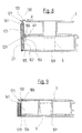
- the locking element 21 can assume two different extreme positions in the spool 9: The spool removal position according to FIG. 2 and the working position according to FIGS. 3 and 4. In the removal position for the coil 3 according to Figure 2, the locking element 21 is located by the force of the spring 23 in its maximum extended position.
- the two feet 29, 31 abut against the two upper ends 43 and 45 of the slots 11 and 13 and prevent the locking element 21 from becoming detached from the spool 9. Because the first slot 11 has a greater axial extent upwards, but the two feet 29, 31 are arranged symmetrically on the locking element 21, the locking element 21 is forcibly moved into an inclined position (see FIG.
- the handle plate 33 moves in the direction of the axis X, so that the rear edge 37 and the front edge 47 of the nose 39 come to lie at the same distance from the axis X.
- This pivoting back of the nose 39 in the direction of the axis of rotation X causes the coil 3 is now freely guided axially over the locking element 21 and removed or placed.
- this is inserted axially until the lower flange 49 of the coil 3 rests for the time being on the higher foot 29 of the locking element 21.
- the locking element 21 is in the unlocked position thanks to play in the bore 10 in the spool 9 obliquely and thereby releases the coil 3.
- the inclined position of the locking element 21 in the extended position according to FIG. 2 could also be achieved if, with the same axial length of the two slots 11, 13, the foot 31 facing the nose 39 would have a greater axial thickness (cf. Line 51 in FIG. 5).
- this design has the disadvantage that the overall height of the bobbin 1 is correspondingly increased, the height of the coil 3 is reduced or the coil would have to be undercut in the central area, so that the additional axial height of the foot 31 can find room in the recess 15.
- the locking element 121 is arranged peripherally on the coil carrier 101.
- the bobbin 101 can also be produced without a central spool, and the locking element 121 is guided in an axial slot 104, which is embedded in the lateral surface 102 of the bobbin 101 (FIGS. 8 and 9).
- the locking element 121 comprises a handle plate 133, a foot 129 and two legs 125 connecting the handle plate 133 and the foot 129.
- the foot 129 and a nose 139 which is part of the handle plate 133, project beyond the surface of the leg 125 and act as stops for the lower flange 49 of the coil 3 and the upper flange of the coil 3.
- the spring 23 is supported at its lower end on the bottom 105 of the bobbin 101.
- the upper end of the spring 23 abuts against a paragraph 141 arranged at a distance from the underside of the handle plate 133 and the nose 139.
- coil 3 are the flanges of the coil 3 with clearance between the foot 129 and the nose 139.
- the paragraph 141 is applied to the upper end 106 of the axial slot 104 pressed by the spring 23 at.
- Invention may be the locking element, similar as in Figures 1 to 5, within the spool 9 to be arranged vertically displaceable and a mechanism include, as with pens for the movement of Mine is used. With the ballpoint pen mechanics known scenes it is also possible to release a locking position by axial pressure and with a spring an axial feed movement trigger and on pressing the latch again to activate again.
- the grip plates 33, 133 are designed in such a way that the lower thread can not catch on being pulled off and also the triggering properties are not impaired.
- the handle plate 33,133 may be formed in the direction of the nose 39,139 out with a suit that the locking element 21,121, if it has been accidentally placed without coil 3 in the inserted position, when pushing a coil 3 is unlocked immediately by the hollow coil mandrel pushes and by reinserting the coil 3 again assumes the coil-locking position.
Abstract
Description
Aus der DE-A1 3819405 ist eine Spulenkapsel für Umlaufgreifer bekannt, bei der die Spule auf einem zylindrischen Spulendorn, der Teil der Spulenkapsel ist, aufgeschoben und von einem Sicherungshebel gehalten ist. Der Sicherungshebel, als zweiarmiger Hebel ausgebildet, wird in den beiden Stellungen (Offenstellung und Arbeitsstellung) von einer federbelasteten Platte gehalten. Das Lösen der Verriegelung erfolgt durch manuelles Schwenken des Hebels um 90°in eine achsparallele Lage. Danach kann die Spule aus dem Spulenträger herausgehoben werden. Um das Herausheben der Spule aus dem Spulenträger zu erleichtern, wird in der DE-A1 1951038 vorgeschlagen, zwischen Spulenunterseite, d.h. dem untenliegenden Spulenflansch, und dem Spulenträger eine Schraubenfeder einzulegen. Diese drückt nach Freigabe der Spule durch den Hebel die Spule teilweise aus dem Spulenträger hinaus. Gleichzeitig übt die Feder während des Nähens ein Bremsmoment auf die Spule aus, welches je nach Ausbildung der Spulenoberfläche unterschiedlich ausfällt und nicht beeinflussbar ist. Dies kann den Nähvorgang behindern.
Aus der GB-A 2149433 ist weiter ein Spulenhalter bekannt, bei dem die Spule durch einen federbelasteten durch die Spule hindurchführbaren Haltedorn gehalten wird. Der Haltedorn kann durch eine Viertelsdrehung aus der Haltein die Entnahmestellung gebracht werden und löst sich zusammen mit der Spule vollständig vom Spulenträger. Der Haltedorn muss folglich beim Einlegen einer vollen Spule in diese eingeführt und danach gesichert werden.
- Figur 1
- eine perspektivische Explosionsdarstellung eines Spulenträgers mit dem Verriegelungselement und einer Spule,
- Figur 2
- einen Axialschnitt durch den Spulenträger mit ausgeworfener Spule,
- Figur 3
- einen Axialschnitt durch den Spulenträger mit verriegelter Spule und
- Figur 4
- eine vergrösserte Darstellung des Ausschnitts A in Figur 3,
- Figur 5
- eine Seitenansicht des Verriegelungselementes,
- Figur 6
- einen Querschnitt durch das Verriegelungselement längs Linie V - V in Figur 5,
- Figur 7
- eine perspektivische Explosionsdarstellung eines Spulenträgers mit einem Verriegelungselement und einer Spule in einer weiteren Ausgestaltung der Erfindung,
- Figur 8
- einen Axialschnitt durch den Spulenträger mit ausgeworfener Spule gemäss Figur 7,
- Figur 9
- einen Axialschnitt durch den Spulenträger mit verriegelter Spule,
- Figur 10
- einen Axialschnitt durch den Spulenträger mit ausgeworfener Spule in einer weiteren Ausgestaltung der Erfindung.
Die beiden Füsse 29,31 überragen den Mantel des Spulendorns 9, wenn das Verriegelungselement 21 in die Bohrung 10 im Spulenträger 1 bzw. in den Spulendorn 9 im Spulenträger 1 eingesetzt ist. Sie werden seitlich in den beiden Schlitzen 11,13 geführt (vgl. Figur 2). Die Feder 23 ist unten auf dem Steg 19 und oben an der Unterseite der Griffplatte 33 abgestützt.
Das Verriegelungselement 21 kann im Spulendorn 9 zwei unterschiedliche Extrem-Stellungen einnehmen: Die Spulen-Entnahmeposition gemäss Figur 2 und die Arbeitsposition gemäss den Figuren 3 und 4.
In der Entnahmeposition für die Spule 3 gemäss Figur 2 liegt das Verriegelungselement 21 durch die Kraft der Feder 23 in seiner maximal ausgefahrenen Position. Die beiden Füsse 29,31 liegen an den beiden oberen Enden 43 und 45 der Schlitze 11 und 13 an und verhindern, dass sich das Verriegelungselement 21 vom Spulendorn 9 löst. Weil der erste Schlitz 11 nach oben eine grössere axiale Ausdehnung aufweist, die beiden Füsse 29,31 jedoch symmetrisch am Verriegelungselement 21 angeordnet sind, gelangt das Verriegelungselement 21 zwangsweise in eine Schrägstellung (vgl. Figur 2). Durch die Schrägstellung des Verriegelungselements 21 bezüglich der Spulenträgerachse X verschiebt sich auch die Griffplatte 33 in Richtung zur Achse X hin, so dass deren rückwärtige Kante 37 und die Vorderkante 47 der Nase 39 in gleichem Abstand zur Achse X zu liegen kommen. Dieses Zurückschwenken der Nase 39 in Richtung auf die Drehachse X bewirkt, dass die Spule 3 nun ungehindert axial über das Verriegelungselement 21 geführt und entnommen bzw. aufgesetzt werden kann. Beim Einsetzen der neuen Spule 3 wird diese axial eingeschoben, bis der untere Flansch 49 der Spule 3 vorerst am höher liegenden Fuss 29 des Verriegelungselements 21 anliegt. Durch einen weiteren Druck mit einer Kraft F auf die Spule 3 oder auf die Griffplatte 33 drückt diese das Verriegelungselement 21 gegen die Kraft der Feder 23 sukzessive nach unten. Spätestens wenn der Flansch 49 am Boden 5 des Spulenträgers 1 anstösst, kippt das Verriegelungselement 21 im Uhrzeigersinn und der Absatz 41 unter der Nase 39 rastet am oberen Ende 43 des Schlitzes 11 im Spulendorn 9 ein (Figuren 3 und 4). Die beiden Füsse 29,31 liegen nun parallel zum Boden 5 und zum unteren Flansch 49 der Spule 3. Da der Abstand a zwischen der Unterseite der Nase 39 und der Oberseite des Bodens 5 grösser ist als die gesamte axiale Länge L der Spule 3 (vgl. Figur 3), liegt diese mit Spiel im Spulenträger 1 gehalten. Durch die Kraft der Feder 23 bleibt die Verrastung des Verriegelungselements 21 so lange aufrecht erhalten, bis durch die Bedienungsperson der Nähmaschine eine radiale Verschiebekraft R auf die Nase 39 des Verriegelungselements 21 ausgeübt wird, um die Spule 3 zu entnehmen. Durch die Kraft R schwenkt das Verriegelungselement 21 in Figur 3 im Gegenuhrzeigersinn, der Absatz 41 löst sich aus dem Schlitz 11 und die Spule 3 wird durch die Kraft der Feder 23 zusammen mit dem Verriegelungselement 21 aus dem Innern des Spulenträgers 1 mindestens teilweise herausgeschoben und kann entnommen werden.
In einer weiteren Ausgestaltung der Erfindung gemäss Figur 10 kann im Spulendorn 9 nur ein Schlitz 13 ausgebildet sein, in den ein einziger Fuss 31 am Verriegelungselement 21 eingreift. Das Verriegelungselement 21 stellt sich in entriegelter Stellung dank Spiel in der Bohrung 10 im Spulendorn 9 schräg und gibt dadurch die Spule 3 frei.
Die Schrägstellung des Verriegelungselements 21 in der ausgefahrenen Stellung gemäss Figur 2 könnte alternativ auch dadurch erreicht werden, dass bei gleicher axialer Länge der beiden Schlitze 11,13 der Fuss 31, der der Nase 39 gegenüberliegt, eine grössere axiale Dicke aufweisen würde (vgl. gestrichelte Linie 51 in Figur 5). Diese Ausführung hat allerdings den Nachteil, dass die Bauhöhe des Spulenträgers 1 entsprechend vergrössert, die Höhe der Spule 3 verkleinert oder die Spule im zentralen Bereich hinterschnitten werden müsste, damit die zusätzliche axiale Höhe des Fusses 31 in der Ausnehmung 15 Raum finden kann.
Bei vollständig in den Spulenträger 101 eingeführter Spule 3 liegen die Flanschen der Spule 3 mit Spiel zwischen dem Fuss 129 und der Nase 139. Der Absatz 141 liegt am oberen Ende 106 des axialen Schlitzes 104 durch die Feder 23 angepresst an.
Zum Entriegeln der Spule 3 und Herausnehmen der letzteren aus dem Spulenträger 101 wird auf die Griffplatte 133 eine Kraft in Richtung des Pfeiles R ausgeübt, bis der Absatz 141 ausser Eingriff mit dem oberen Ende 106 des Schlitzes 104 geführt ist und dadurch das Verriegelungselement 121 durch die Kraft der Feder 23 so weit nach oben geführt wird, bis der Fuss 129 am oberen Ende 106 des Schlitzes 104 anliegt (Figur 8). Durch die verschiebende Kraft R wird das Verriegelungselement 121 geschwenkt und die Spule 3 kann ungehindert aus dem Spulenträger 101 herausgehoben werden.
Bei eingelegter Spule 103 gemäss Figur 9 wird die Spule 3 durch das Verriegelungselement mit Spiel gehalten, d.h. es findet keine bremsende unkontrollierbare Krafteinwirkung auf die Spule während des Nähens statt.
Im weiteren kann die Griffplatte 33,133 in Richtung zur Nase 39,139 hin derart mit Anzug geformt sein, dass das Verriegelungselement 21,121, wenn es aus Versehen ohne Spule 3 in die eingeschobene Stellung gebracht worden ist, beim Darüberschieben einer Spule 3 sofort entriegelt wird, sich durch den hohlen Spulendorn schiebt und durch das weitere Einschieben der Spule 3 erneut die Spulen-Verriegelungsstellung einnimmt.
Claims (12)
- Verriegelungsvorrichtung für eine Unterfadenspule (3) in einem Spulenträger (1,101) einer Nähmaschine, umfassend einen Aufnahmeraum im Spulenträger (1,101) für die Unterfadenspule (3) und ein Verriegelungselement (21) zum Festhalten der Unterfadenspule (3) im Spulenträger (1),
dadurch gekennzeichnet, dass
das Verriegelungselement (21) im Spulenträger (1,101) verschiebbar geführt und in diesem durch die Kraft einer Feder (23) in der Verriegelungsstellung und in der Entriegelungsstellung gehalten ist. - Verriegelungsvorrichtung nach Anspruch 1, dadurch gekennzeichnet, dass das Verriegelungselement (21) axial verschiebbar und gegen Verdrehung gesichert in einem Spulendorn (9) im Spulenträger (1) gehalten ist.
- Verriegelungsvorrichtung nach Anspruch 2, dadurch gekennzeichnet, dass der Spulendorn (9) eine zentrale Bohrung (10) umfasst, in der das Verriegelungselement (21) geführt ist.
- Verriegelungsvorrichtung nach den Ansprüchen 1 bis 3, dadurch gekennzeichnet, dass im Verriegelungselement (21) eine axial verlaufende Sackbohrung (32) angebracht ist, in welcher eine Feder (23) eingesetzt und mit einem ihrer Enden abgestützt ist.
- Verriegelungsvorrichtung nach Anspruch 4, dadurch gekennzeichnet, dass die Feder (23) mit ihrem zweiten Ende auf dem Boden (5) oder dem Steg (19) des Spulenträgers (1) abgestützt ist.
- Verriegelungsvorrichtung nach Anspruch 1 bis 5, dadurch gekennzeichnet, dass am Spulendorn (9) mindestens ein axial verlaufender Schlitz (11,13) eingelassen ist, in dem ein Fuss (29,31), welcher am Verriegelungselement (21) angeformt ist, hineinragt.
- Verriegelungsvorrichtung nach Anspruch 6, dadurch gekennzeichnet, dass bei mehr als einem Schlitz (13) einer der Schlitze (11) länger ist als der mindestens eine andere Schlitz (13).
- Verriegelungsvorrichtung nach Anspruch 6 oder 7, dadurch gekennzeichnet, dass am Verriegelungselement (21) eine Griffplatte (33) mit einer Nase (39) angeformt ist, welche die Manteloberfläche (22) über einem der Füsse (29) des Verriegelungselements (21) überragt.
- Verriegelungsvorrichtung nach Anspruch 8, dadurch gekennzeichnet, dass axial versetzt zur Oberfläche der Griffplatte (33) ein Absatz (41) ausgebildet ist, welcher bei in den Spulendorn (9) eingeschobenem Verriegelungselement (21) im Schlitz (11) einrastet.
- Verriegelungsvorrichtung nach Anspruch 5 bis 9, dadurch gekennzeichnet, dass im Boden (5) des Spulenträgers (1) unterhalb des mindestens einen Fusses (29,31) eine Ausnehmung (15,17) eingelassen ist, in welche der mindestens eine Fuss (29,31) bei in den Spulenträger (1) eingesetzter Spule (3) eingreift.
- Verriegelungsvorrichtung nach Anspruch 1, dadurch gekennzeichnet, dass das Verriegelungselement (121) in einem axialen Schlitz (104) in der Mantelfläche des Spulenträgers (101) axial verschiebbar und arretierbar geführt ist.
- Verriegelungsvorrichtung nach Anspruch 11, dadurch gekennzeichnet, dass das Verriegelungselement (121) einen Fuss (129), eine Griffplatte (133) und beabstandet dazu einen Absatz (141) und mindestens ein den Fuss (129) und die Griffplatte (133) verbindendes Bein (125) sowie eine Feder (23) umfasst, wobei der Absatz (141) und der Fuss (129) die beiden Extremlagen des Verriegelungselementes (121) im Spulenträger (101) bestimmen.
Applications Claiming Priority (2)
| Application Number | Priority Date | Filing Date | Title |
|---|---|---|---|
| CH21052003 | 2003-12-10 | ||
| CH21052003 | 2003-12-10 |
Publications (3)
| Publication Number | Publication Date |
|---|---|
| EP1541736A2 true EP1541736A2 (de) | 2005-06-15 |
| EP1541736A3 EP1541736A3 (de) | 2006-04-26 |
| EP1541736B1 EP1541736B1 (de) | 2008-05-21 |
Family
ID=34468809
Family Applications (1)
| Application Number | Title | Priority Date | Filing Date |
|---|---|---|---|
| EP04405582A Not-in-force EP1541736B1 (de) | 2003-12-10 | 2004-09-16 | Verriegelungsvorrichtung für eine Unterfadenspule |
Country Status (4)
| Country | Link |
|---|---|
| US (1) | US7036444B2 (de) |
| EP (1) | EP1541736B1 (de) |
| AT (1) | ATE396293T1 (de) |
| DE (1) | DE502004007215D1 (de) |
Cited By (6)
| Publication number | Priority date | Publication date | Assignee | Title |
|---|---|---|---|---|
| EP2103725A1 (de) * | 2008-03-19 | 2009-09-23 | Dürkopp Adler AG | Greifer für eine Doppel-Steppstich-Nähmaschine |
| EP2138623A1 (de) * | 2008-06-24 | 2009-12-30 | Dürkopp Adler AG | Greifer für eine Doppel-Steppstich-Nähmaschine |
| EP2221410A1 (de) * | 2009-02-17 | 2010-08-25 | BERNINA International AG | Verriegelungsvorrichtung für eine Spulenkapsel für eine Unterfadenspule |
| ITVI20100069A1 (it) * | 2010-03-15 | 2011-09-16 | Gilberto Cracco | Gruppo crochet perfezionato, particolarmente per macchine da cucire. |
| EP2463430A1 (de) * | 2010-12-09 | 2012-06-13 | BERNINA International AG | Verriegelungsvorrichtung für eine Spulenkapsel |
| CN104278437A (zh) * | 2013-07-03 | 2015-01-14 | 启翔股份有限公司 | 缝纫机水平旋梭 |
Families Citing this family (3)
| Publication number | Priority date | Publication date | Assignee | Title |
|---|---|---|---|---|
| JP2012115595A (ja) * | 2010-12-03 | 2012-06-21 | Brother Ind Ltd | ボビン及びミシン |
| USD843977S1 (en) * | 2017-07-11 | 2019-03-26 | Aiwu Wang | Winder |
| JP1610198S (de) * | 2017-09-25 | 2018-07-30 |
Citations (2)
| Publication number | Priority date | Publication date | Assignee | Title |
|---|---|---|---|---|
| GB2149433A (en) * | 1983-11-07 | 1985-06-12 | Singer Co | Bobbin and plunger assembly |
| DE3819405A1 (de) * | 1987-06-15 | 1988-12-29 | Elitex Zavody Textilniho | Spulenkapsel fuer umlaufgreifer von naehmaschinen |
Family Cites Families (6)
| Publication number | Priority date | Publication date | Assignee | Title |
|---|---|---|---|---|
| US663675A (en) * | 1900-08-07 | 1900-12-11 | Singer Mfg Co | Bobbin-case holder and bobbin-ejector for sewing-machines. |
| US832414A (en) * | 1905-11-16 | 1906-10-02 | Wheeler & Wilson Mfg Co | Sewing-machine bobbin-case. |
| US2813500A (en) * | 1951-06-26 | 1957-11-19 | Singer Mfg Co | Bobbin-cases for sewing machines |
| US2848965A (en) * | 1954-01-25 | 1958-08-26 | White Sewing Machine Corp | Sewing machine |
| US3381643A (en) * | 1966-10-10 | 1968-05-07 | Singer Co | Bobbin-supporting assemblies for sewing machines |
| DE19510830C2 (de) | 1995-03-24 | 2001-11-22 | Duerkopp Adler Ag | Spulenbremse für die Greiferfaden-Spule einer Doppelsteppstich-Nähmaschine |
-
2004
- 2004-09-16 AT AT04405582T patent/ATE396293T1/de not_active IP Right Cessation
- 2004-09-16 EP EP04405582A patent/EP1541736B1/de not_active Not-in-force
- 2004-09-16 DE DE502004007215T patent/DE502004007215D1/de active Active
- 2004-10-19 US US10/968,738 patent/US7036444B2/en active Active
Patent Citations (2)
| Publication number | Priority date | Publication date | Assignee | Title |
|---|---|---|---|---|
| GB2149433A (en) * | 1983-11-07 | 1985-06-12 | Singer Co | Bobbin and plunger assembly |
| DE3819405A1 (de) * | 1987-06-15 | 1988-12-29 | Elitex Zavody Textilniho | Spulenkapsel fuer umlaufgreifer von naehmaschinen |
Cited By (10)
| Publication number | Priority date | Publication date | Assignee | Title |
|---|---|---|---|---|
| EP2103725A1 (de) * | 2008-03-19 | 2009-09-23 | Dürkopp Adler AG | Greifer für eine Doppel-Steppstich-Nähmaschine |
| KR101534860B1 (ko) * | 2008-03-19 | 2015-07-07 | 뒤르콥 아들러 악티엔게젤샤프트 | 록스티치 재봉틀용 후크 |
| EP2138623A1 (de) * | 2008-06-24 | 2009-12-30 | Dürkopp Adler AG | Greifer für eine Doppel-Steppstich-Nähmaschine |
| CN101613915B (zh) * | 2008-06-24 | 2012-12-12 | 杜尔克普-阿德勒股份公司 | 用于双锁式线迹缝纫机的旋梭 |
| EP2221410A1 (de) * | 2009-02-17 | 2010-08-25 | BERNINA International AG | Verriegelungsvorrichtung für eine Spulenkapsel für eine Unterfadenspule |
| CH700442A1 (de) * | 2009-02-17 | 2010-08-31 | Bernina Int Ag | Verriegelungsvorrichtung für eine Spulenkapsel für eine Unterfadenspule. |
| ITVI20100069A1 (it) * | 2010-03-15 | 2011-09-16 | Gilberto Cracco | Gruppo crochet perfezionato, particolarmente per macchine da cucire. |
| EP2463430A1 (de) * | 2010-12-09 | 2012-06-13 | BERNINA International AG | Verriegelungsvorrichtung für eine Spulenkapsel |
| US8622009B2 (en) | 2010-12-09 | 2014-01-07 | Bernina International Ag | Locking mechanism for a bobbin case |
| CN104278437A (zh) * | 2013-07-03 | 2015-01-14 | 启翔股份有限公司 | 缝纫机水平旋梭 |
Also Published As
| Publication number | Publication date |
|---|---|
| US7036444B2 (en) | 2006-05-02 |
| EP1541736B1 (de) | 2008-05-21 |
| EP1541736A3 (de) | 2006-04-26 |
| US20050126461A1 (en) | 2005-06-16 |
| ATE396293T1 (de) | 2008-06-15 |
| DE502004007215D1 (de) | 2008-07-03 |
Similar Documents
| Publication | Publication Date | Title |
|---|---|---|
| EP0340750B1 (de) | Langbügelschloss | |
| DE69826499T2 (de) | Schneidwerkzeug | |
| DE4136840C2 (de) | Lenkwellen-Sperrvorrichtung | |
| WO1991010541A1 (de) | Spannfutter für mehrkantige schaftenden von werkzeugen | |
| DE3831076A1 (de) | Schliess-system | |
| EP0369107A2 (de) | Zylinderschloss | |
| EP1491295B1 (de) | Verriegelungsbolzen zur Befestigung eines Werkzeuges an einem hydraulischen Verpressgerät | |
| DE2309396C3 (de) | Vorrichtung für Einsatzschraubenschlüssel zur lösbaren axialen Befestigung eines Steckschlüssels | |
| DE2729151A1 (de) | Verschlusstueck fuer eine sitzgurtschnalle | |
| EP1541736B1 (de) | Verriegelungsvorrichtung für eine Unterfadenspule | |
| WO1998057832A1 (de) | Seilzugeinstellung | |
| WO2006125653A1 (de) | Verbindung zwischen zwei werkzeugteilen | |
| EP0830261B1 (de) | Anhängevorrichtung | |
| DE10335311B4 (de) | Lenkschlossvorrichtung | |
| CH680400A5 (de) | ||
| EP1256669B1 (de) | Schliesszylinder | |
| EP3296163B1 (de) | Gesicherte vorrichtung zum sperren eines funktionswesentlichen bauteils eines kraftfahrzeugs | |
| DE3411138A1 (de) | Auswerfmechanismus fuer ein bandabspielgeraet | |
| EP1201853B1 (de) | Obere Verschlussstellenvorrichtung für Schlösser von Nottüren | |
| CH700442A1 (de) | Verriegelungsvorrichtung für eine Spulenkapsel für eine Unterfadenspule. | |
| EP0287799A1 (de) | Beschlag für mit Schliesszylinder ausgerüstete Türen oder dergleichen | |
| DE2707838A1 (de) | Sicherheitsskibindung mit an einem grundkoerper schwenkbar angeordnetem sohlenhalter und einer eingebauten skibremse | |
| DE102005049452A1 (de) | Rückenlehne für ein Fahrzeug | |
| DE60301342T2 (de) | Verbessertes zuhaltungsscheibenschloss | |
| DE4117354C2 (de) | Drehstangenschloß |
Legal Events
| Date | Code | Title | Description |
|---|---|---|---|
| PUAI | Public reference made under article 153(3) epc to a published international application that has entered the european phase |
Free format text: ORIGINAL CODE: 0009012 |
|
| AK | Designated contracting states |
Kind code of ref document: A2 Designated state(s): AT BE BG CH CY CZ DE DK EE ES FI FR GB GR HU IE IT LI LU MC NL PL PT RO SE SI SK TR |
|
| AX | Request for extension of the european patent |
Extension state: AL HR LT LV MK |
|
| PUAL | Search report despatched |
Free format text: ORIGINAL CODE: 0009013 |
|
| AK | Designated contracting states |
Kind code of ref document: A3 Designated state(s): AT BE BG CH CY CZ DE DK EE ES FI FR GB GR HU IE IT LI LU MC NL PL PT RO SE SI SK TR |
|
| AX | Request for extension of the european patent |
Extension state: AL HR LT LV MK |
|
| 17P | Request for examination filed |
Effective date: 20060518 |
|
| RAP1 | Party data changed (applicant data changed or rights of an application transferred) |
Owner name: FRITZ GEGAUF AG |
|
| AKX | Designation fees paid |
Designated state(s): AT BE BG CH CY CZ DE DK EE ES FI FR GB GR HU IE IT LI LU MC NL PL PT RO SE SI SK TR |
|
| 17Q | First examination report despatched |
Effective date: 20061228 |
|
| RAP1 | Party data changed (applicant data changed or rights of an application transferred) |
Owner name: BERNINA INTERNATIONAL AG |
|
| GRAP | Despatch of communication of intention to grant a patent |
Free format text: ORIGINAL CODE: EPIDOSNIGR1 |
|
| GRAS | Grant fee paid |
Free format text: ORIGINAL CODE: EPIDOSNIGR3 |
|
| GRAA | (expected) grant |
Free format text: ORIGINAL CODE: 0009210 |
|
| AK | Designated contracting states |
Kind code of ref document: B1 Designated state(s): AT BE BG CH CY CZ DE DK EE ES FI FR GB GR HU IE IT LI LU MC NL PL PT RO SE SI SK TR |
|
| REG | Reference to a national code |
Ref country code: GB Ref legal event code: FG4D Free format text: NOT ENGLISH |
|
| REG | Reference to a national code |
Ref country code: CH Ref legal event code: EP Ref country code: CH Ref legal event code: NV Representative=s name: GACHNANG AG PATENTANWAELTE |
|
| REF | Corresponds to: |
Ref document number: 502004007215 Country of ref document: DE Date of ref document: 20080703 Kind code of ref document: P |
|
| REG | Reference to a national code |
Ref country code: IE Ref legal event code: FG4D Free format text: LANGUAGE OF EP DOCUMENT: GERMAN |
|
| REG | Reference to a national code |
Ref country code: SE Ref legal event code: TRGR |
|
| PG25 | Lapsed in a contracting state [announced via postgrant information from national office to epo] |
Ref country code: SI Free format text: LAPSE BECAUSE OF FAILURE TO SUBMIT A TRANSLATION OF THE DESCRIPTION OR TO PAY THE FEE WITHIN THE PRESCRIBED TIME-LIMIT Effective date: 20080521 |
|
| PG25 | Lapsed in a contracting state [announced via postgrant information from national office to epo] |
Ref country code: ES Free format text: LAPSE BECAUSE OF FAILURE TO SUBMIT A TRANSLATION OF THE DESCRIPTION OR TO PAY THE FEE WITHIN THE PRESCRIBED TIME-LIMIT Effective date: 20080901 Ref country code: FI Free format text: LAPSE BECAUSE OF FAILURE TO SUBMIT A TRANSLATION OF THE DESCRIPTION OR TO PAY THE FEE WITHIN THE PRESCRIBED TIME-LIMIT Effective date: 20080521 |
|
| NLV1 | Nl: lapsed or annulled due to failure to fulfill the requirements of art. 29p and 29m of the patents act | ||
| PG25 | Lapsed in a contracting state [announced via postgrant information from national office to epo] |
Ref country code: NL Free format text: LAPSE BECAUSE OF FAILURE TO SUBMIT A TRANSLATION OF THE DESCRIPTION OR TO PAY THE FEE WITHIN THE PRESCRIBED TIME-LIMIT Effective date: 20080521 Ref country code: PL Free format text: LAPSE BECAUSE OF FAILURE TO SUBMIT A TRANSLATION OF THE DESCRIPTION OR TO PAY THE FEE WITHIN THE PRESCRIBED TIME-LIMIT Effective date: 20080521 |
|
| PGFP | Annual fee paid to national office [announced via postgrant information from national office to epo] |
Ref country code: CZ Payment date: 20080909 Year of fee payment: 5 |
|
| REG | Reference to a national code |
Ref country code: IE Ref legal event code: FD4D |
|
| PG25 | Lapsed in a contracting state [announced via postgrant information from national office to epo] |
Ref country code: PT Free format text: LAPSE BECAUSE OF FAILURE TO SUBMIT A TRANSLATION OF THE DESCRIPTION OR TO PAY THE FEE WITHIN THE PRESCRIBED TIME-LIMIT Effective date: 20081021 Ref country code: DK Free format text: LAPSE BECAUSE OF FAILURE TO SUBMIT A TRANSLATION OF THE DESCRIPTION OR TO PAY THE FEE WITHIN THE PRESCRIBED TIME-LIMIT Effective date: 20080521 Ref country code: IE Free format text: LAPSE BECAUSE OF FAILURE TO SUBMIT A TRANSLATION OF THE DESCRIPTION OR TO PAY THE FEE WITHIN THE PRESCRIBED TIME-LIMIT Effective date: 20080521 |
|
| PG25 | Lapsed in a contracting state [announced via postgrant information from national office to epo] |
Ref country code: SK Free format text: LAPSE BECAUSE OF FAILURE TO SUBMIT A TRANSLATION OF THE DESCRIPTION OR TO PAY THE FEE WITHIN THE PRESCRIBED TIME-LIMIT Effective date: 20080521 Ref country code: RO Free format text: LAPSE BECAUSE OF FAILURE TO SUBMIT A TRANSLATION OF THE DESCRIPTION OR TO PAY THE FEE WITHIN THE PRESCRIBED TIME-LIMIT Effective date: 20080521 |
|
| PLBE | No opposition filed within time limit |
Free format text: ORIGINAL CODE: 0009261 |
|
| STAA | Information on the status of an ep patent application or granted ep patent |
Free format text: STATUS: NO OPPOSITION FILED WITHIN TIME LIMIT |
|
| BERE | Be: lapsed |
Owner name: BERNINA INTERNATIONAL A.G. Effective date: 20080930 |
|
| 26N | No opposition filed |
Effective date: 20090224 |
|
| PG25 | Lapsed in a contracting state [announced via postgrant information from national office to epo] |
Ref country code: BG Free format text: LAPSE BECAUSE OF FAILURE TO SUBMIT A TRANSLATION OF THE DESCRIPTION OR TO PAY THE FEE WITHIN THE PRESCRIBED TIME-LIMIT Effective date: 20080821 Ref country code: EE Free format text: LAPSE BECAUSE OF FAILURE TO SUBMIT A TRANSLATION OF THE DESCRIPTION OR TO PAY THE FEE WITHIN THE PRESCRIBED TIME-LIMIT Effective date: 20080521 Ref country code: MC Free format text: LAPSE BECAUSE OF NON-PAYMENT OF DUE FEES Effective date: 20080930 |
|
| REG | Reference to a national code |
Ref country code: FR Ref legal event code: ST Effective date: 20090529 |
|
| PG25 | Lapsed in a contracting state [announced via postgrant information from national office to epo] |
Ref country code: BE Free format text: LAPSE BECAUSE OF NON-PAYMENT OF DUE FEES Effective date: 20080930 |
|
| PG25 | Lapsed in a contracting state [announced via postgrant information from national office to epo] |
Ref country code: IT Free format text: LAPSE BECAUSE OF FAILURE TO SUBMIT A TRANSLATION OF THE DESCRIPTION OR TO PAY THE FEE WITHIN THE PRESCRIBED TIME-LIMIT Effective date: 20080521 |
|
| PG25 | Lapsed in a contracting state [announced via postgrant information from national office to epo] |
Ref country code: FR Free format text: LAPSE BECAUSE OF NON-PAYMENT OF DUE FEES Effective date: 20080930 Ref country code: AT Free format text: LAPSE BECAUSE OF NON-PAYMENT OF DUE FEES Effective date: 20080916 |
|
| PGFP | Annual fee paid to national office [announced via postgrant information from national office to epo] |
Ref country code: GB Payment date: 20090902 Year of fee payment: 6 Ref country code: SE Payment date: 20090929 Year of fee payment: 6 |
|
| PG25 | Lapsed in a contracting state [announced via postgrant information from national office to epo] |
Ref country code: CZ Free format text: LAPSE BECAUSE OF NON-PAYMENT OF DUE FEES Effective date: 20090916 |
|
| PG25 | Lapsed in a contracting state [announced via postgrant information from national office to epo] |
Ref country code: LU Free format text: LAPSE BECAUSE OF NON-PAYMENT OF DUE FEES Effective date: 20080916 Ref country code: CY Free format text: LAPSE BECAUSE OF FAILURE TO SUBMIT A TRANSLATION OF THE DESCRIPTION OR TO PAY THE FEE WITHIN THE PRESCRIBED TIME-LIMIT Effective date: 20080521 Ref country code: HU Free format text: LAPSE BECAUSE OF FAILURE TO SUBMIT A TRANSLATION OF THE DESCRIPTION OR TO PAY THE FEE WITHIN THE PRESCRIBED TIME-LIMIT Effective date: 20081122 |
|
| PG25 | Lapsed in a contracting state [announced via postgrant information from national office to epo] |
Ref country code: TR Free format text: LAPSE BECAUSE OF FAILURE TO SUBMIT A TRANSLATION OF THE DESCRIPTION OR TO PAY THE FEE WITHIN THE PRESCRIBED TIME-LIMIT Effective date: 20080521 |
|
| PG25 | Lapsed in a contracting state [announced via postgrant information from national office to epo] |
Ref country code: GR Free format text: LAPSE BECAUSE OF FAILURE TO SUBMIT A TRANSLATION OF THE DESCRIPTION OR TO PAY THE FEE WITHIN THE PRESCRIBED TIME-LIMIT Effective date: 20080822 |
|
| REG | Reference to a national code |
Ref country code: SE Ref legal event code: EUG |
|
| GBPC | Gb: european patent ceased through non-payment of renewal fee |
Effective date: 20100916 |
|
| PG25 | Lapsed in a contracting state [announced via postgrant information from national office to epo] |
Ref country code: GB Free format text: LAPSE BECAUSE OF NON-PAYMENT OF DUE FEES Effective date: 20100916 |
|
| PG25 | Lapsed in a contracting state [announced via postgrant information from national office to epo] |
Ref country code: SE Free format text: LAPSE BECAUSE OF NON-PAYMENT OF DUE FEES Effective date: 20100917 |
|
| PGFP | Annual fee paid to national office [announced via postgrant information from national office to epo] |
Ref country code: CH Payment date: 20200929 Year of fee payment: 17 |
|
| PGFP | Annual fee paid to national office [announced via postgrant information from national office to epo] |
Ref country code: DE Payment date: 20201127 Year of fee payment: 17 |
|
| REG | Reference to a national code |
Ref country code: DE Ref legal event code: R119 Ref document number: 502004007215 Country of ref document: DE |
|
| REG | Reference to a national code |
Ref country code: CH Ref legal event code: PL |
|
| PG25 | Lapsed in a contracting state [announced via postgrant information from national office to epo] |
Ref country code: DE Free format text: LAPSE BECAUSE OF NON-PAYMENT OF DUE FEES Effective date: 20220401 |
|
| PG25 | Lapsed in a contracting state [announced via postgrant information from national office to epo] |
Ref country code: LI Free format text: LAPSE BECAUSE OF NON-PAYMENT OF DUE FEES Effective date: 20210930 Ref country code: CH Free format text: LAPSE BECAUSE OF NON-PAYMENT OF DUE FEES Effective date: 20210930 |