EP1540201B1 - Procede pour reduire des vibrations de grippage - Google Patents
Procede pour reduire des vibrations de grippage Download PDFInfo
- Publication number
- EP1540201B1 EP1540201B1 EP03753283A EP03753283A EP1540201B1 EP 1540201 B1 EP1540201 B1 EP 1540201B1 EP 03753283 A EP03753283 A EP 03753283A EP 03753283 A EP03753283 A EP 03753283A EP 1540201 B1 EP1540201 B1 EP 1540201B1
- Authority
- EP
- European Patent Office
- Prior art keywords
- clutch
- determined
- juddering
- time
- modulation
- Prior art date
- Legal status (The legal status is an assumption and is not a legal conclusion. Google has not performed a legal analysis and makes no representation as to the accuracy of the status listed.)
- Revoked
Links
- 238000000034 method Methods 0.000 title claims description 100
- 230000005540 biological transmission Effects 0.000 claims abstract description 148
- 238000002485 combustion reaction Methods 0.000 claims abstract description 6
- 238000005259 measurement Methods 0.000 claims description 17
- 230000001419 dependent effect Effects 0.000 claims description 16
- 238000011156 evaluation Methods 0.000 claims description 15
- 230000002123 temporal effect Effects 0.000 claims description 11
- 230000010355 oscillation Effects 0.000 claims description 9
- 230000003534 oscillatory effect Effects 0.000 claims description 3
- 230000009849 deactivation Effects 0.000 claims 1
- 230000008878 coupling Effects 0.000 abstract description 41
- 238000010168 coupling process Methods 0.000 abstract description 41
- 238000005859 coupling reaction Methods 0.000 abstract description 41
- 230000004044 response Effects 0.000 abstract description 3
- 238000013461 design Methods 0.000 description 14
- 230000010363 phase shift Effects 0.000 description 8
- 244000145845 chattering Species 0.000 description 6
- 238000013519 translation Methods 0.000 description 4
- 230000014616 translation Effects 0.000 description 4
- 238000013016 damping Methods 0.000 description 3
- 238000006073 displacement reaction Methods 0.000 description 3
- 230000005484 gravity Effects 0.000 description 3
- 230000029305 taxis Effects 0.000 description 3
- 101100446506 Mus musculus Fgf3 gene Proteins 0.000 description 2
- 230000033228 biological regulation Effects 0.000 description 2
- 230000000694 effects Effects 0.000 description 2
- 238000013459 approach Methods 0.000 description 1
- 230000002238 attenuated effect Effects 0.000 description 1
- 238000006243 chemical reaction Methods 0.000 description 1
- 238000012937 correction Methods 0.000 description 1
- 238000011161 development Methods 0.000 description 1
- 230000018109 developmental process Effects 0.000 description 1
- 230000033001 locomotion Effects 0.000 description 1
- 230000002441 reversible effect Effects 0.000 description 1
Images


Classifications
-
- B—PERFORMING OPERATIONS; TRANSPORTING
- B60—VEHICLES IN GENERAL
- B60W—CONJOINT CONTROL OF VEHICLE SUB-UNITS OF DIFFERENT TYPE OR DIFFERENT FUNCTION; CONTROL SYSTEMS SPECIALLY ADAPTED FOR HYBRID VEHICLES; ROAD VEHICLE DRIVE CONTROL SYSTEMS FOR PURPOSES NOT RELATED TO THE CONTROL OF A PARTICULAR SUB-UNIT
- B60W30/00—Purposes of road vehicle drive control systems not related to the control of a particular sub-unit, e.g. of systems using conjoint control of vehicle sub-units
- B60W30/18—Propelling the vehicle
- B60W30/20—Reducing vibrations in the driveline
-
- F—MECHANICAL ENGINEERING; LIGHTING; HEATING; WEAPONS; BLASTING
- F16—ENGINEERING ELEMENTS AND UNITS; GENERAL MEASURES FOR PRODUCING AND MAINTAINING EFFECTIVE FUNCTIONING OF MACHINES OR INSTALLATIONS; THERMAL INSULATION IN GENERAL
- F16F—SPRINGS; SHOCK-ABSORBERS; MEANS FOR DAMPING VIBRATION
- F16F15/00—Suppression of vibrations in systems; Means or arrangements for avoiding or reducing out-of-balance forces, e.g. due to motion
-
- F—MECHANICAL ENGINEERING; LIGHTING; HEATING; WEAPONS; BLASTING
- F16—ENGINEERING ELEMENTS AND UNITS; GENERAL MEASURES FOR PRODUCING AND MAINTAINING EFFECTIVE FUNCTIONING OF MACHINES OR INSTALLATIONS; THERMAL INSULATION IN GENERAL
- F16D—COUPLINGS FOR TRANSMITTING ROTATION; CLUTCHES; BRAKES
- F16D48/00—External control of clutches
- F16D48/06—Control by electric or electronic means, e.g. of fluid pressure
-
- F—MECHANICAL ENGINEERING; LIGHTING; HEATING; WEAPONS; BLASTING
- F16—ENGINEERING ELEMENTS AND UNITS; GENERAL MEASURES FOR PRODUCING AND MAINTAINING EFFECTIVE FUNCTIONING OF MACHINES OR INSTALLATIONS; THERMAL INSULATION IN GENERAL
- F16F—SPRINGS; SHOCK-ABSORBERS; MEANS FOR DAMPING VIBRATION
- F16F15/00—Suppression of vibrations in systems; Means or arrangements for avoiding or reducing out-of-balance forces, e.g. due to motion
- F16F15/02—Suppression of vibrations of non-rotating, e.g. reciprocating systems; Suppression of vibrations of rotating systems by use of members not moving with the rotating systems
-
- B—PERFORMING OPERATIONS; TRANSPORTING
- B60—VEHICLES IN GENERAL
- B60W—CONJOINT CONTROL OF VEHICLE SUB-UNITS OF DIFFERENT TYPE OR DIFFERENT FUNCTION; CONTROL SYSTEMS SPECIALLY ADAPTED FOR HYBRID VEHICLES; ROAD VEHICLE DRIVE CONTROL SYSTEMS FOR PURPOSES NOT RELATED TO THE CONTROL OF A PARTICULAR SUB-UNIT
- B60W2510/00—Input parameters relating to a particular sub-units
- B60W2510/10—Change speed gearings
- B60W2510/1015—Input shaft speed, e.g. turbine speed
-
- B—PERFORMING OPERATIONS; TRANSPORTING
- B60—VEHICLES IN GENERAL
- B60W—CONJOINT CONTROL OF VEHICLE SUB-UNITS OF DIFFERENT TYPE OR DIFFERENT FUNCTION; CONTROL SYSTEMS SPECIALLY ADAPTED FOR HYBRID VEHICLES; ROAD VEHICLE DRIVE CONTROL SYSTEMS FOR PURPOSES NOT RELATED TO THE CONTROL OF A PARTICULAR SUB-UNIT
- B60W2710/00—Output or target parameters relating to a particular sub-units
- B60W2710/02—Clutches
- B60W2710/021—Clutch engagement state
- B60W2710/022—Clutch actuator position
-
- B—PERFORMING OPERATIONS; TRANSPORTING
- B60—VEHICLES IN GENERAL
- B60W—CONJOINT CONTROL OF VEHICLE SUB-UNITS OF DIFFERENT TYPE OR DIFFERENT FUNCTION; CONTROL SYSTEMS SPECIALLY ADAPTED FOR HYBRID VEHICLES; ROAD VEHICLE DRIVE CONTROL SYSTEMS FOR PURPOSES NOT RELATED TO THE CONTROL OF A PARTICULAR SUB-UNIT
- B60W2710/00—Output or target parameters relating to a particular sub-units
- B60W2710/02—Clutches
- B60W2710/025—Clutch slip, i.e. difference between input and output speeds
-
- B—PERFORMING OPERATIONS; TRANSPORTING
- B60—VEHICLES IN GENERAL
- B60W—CONJOINT CONTROL OF VEHICLE SUB-UNITS OF DIFFERENT TYPE OR DIFFERENT FUNCTION; CONTROL SYSTEMS SPECIALLY ADAPTED FOR HYBRID VEHICLES; ROAD VEHICLE DRIVE CONTROL SYSTEMS FOR PURPOSES NOT RELATED TO THE CONTROL OF A PARTICULAR SUB-UNIT
- B60W2710/00—Output or target parameters relating to a particular sub-units
- B60W2710/06—Combustion engines, Gas turbines
- B60W2710/0644—Engine speed
-
- B—PERFORMING OPERATIONS; TRANSPORTING
- B60—VEHICLES IN GENERAL
- B60W—CONJOINT CONTROL OF VEHICLE SUB-UNITS OF DIFFERENT TYPE OR DIFFERENT FUNCTION; CONTROL SYSTEMS SPECIALLY ADAPTED FOR HYBRID VEHICLES; ROAD VEHICLE DRIVE CONTROL SYSTEMS FOR PURPOSES NOT RELATED TO THE CONTROL OF A PARTICULAR SUB-UNIT
- B60W2710/00—Output or target parameters relating to a particular sub-units
- B60W2710/06—Combustion engines, Gas turbines
- B60W2710/0666—Engine torque
-
- F—MECHANICAL ENGINEERING; LIGHTING; HEATING; WEAPONS; BLASTING
- F16—ENGINEERING ELEMENTS AND UNITS; GENERAL MEASURES FOR PRODUCING AND MAINTAINING EFFECTIVE FUNCTIONING OF MACHINES OR INSTALLATIONS; THERMAL INSULATION IN GENERAL
- F16D—COUPLINGS FOR TRANSMITTING ROTATION; CLUTCHES; BRAKES
- F16D2500/00—External control of clutches by electric or electronic means
- F16D2500/10—System to be controlled
- F16D2500/104—Clutch
- F16D2500/10406—Clutch position
- F16D2500/10412—Transmission line of a vehicle
-
- F—MECHANICAL ENGINEERING; LIGHTING; HEATING; WEAPONS; BLASTING
- F16—ENGINEERING ELEMENTS AND UNITS; GENERAL MEASURES FOR PRODUCING AND MAINTAINING EFFECTIVE FUNCTIONING OF MACHINES OR INSTALLATIONS; THERMAL INSULATION IN GENERAL
- F16D—COUPLINGS FOR TRANSMITTING ROTATION; CLUTCHES; BRAKES
- F16D2500/00—External control of clutches by electric or electronic means
- F16D2500/10—System to be controlled
- F16D2500/104—Clutch
- F16D2500/10443—Clutch type
- F16D2500/1045—Friction clutch
-
- F—MECHANICAL ENGINEERING; LIGHTING; HEATING; WEAPONS; BLASTING
- F16—ENGINEERING ELEMENTS AND UNITS; GENERAL MEASURES FOR PRODUCING AND MAINTAINING EFFECTIVE FUNCTIONING OF MACHINES OR INSTALLATIONS; THERMAL INSULATION IN GENERAL
- F16D—COUPLINGS FOR TRANSMITTING ROTATION; CLUTCHES; BRAKES
- F16D2500/00—External control of clutches by electric or electronic means
- F16D2500/30—Signal inputs
- F16D2500/304—Signal inputs from the clutch
- F16D2500/30402—Clutch friction coefficient
-
- F—MECHANICAL ENGINEERING; LIGHTING; HEATING; WEAPONS; BLASTING
- F16—ENGINEERING ELEMENTS AND UNITS; GENERAL MEASURES FOR PRODUCING AND MAINTAINING EFFECTIVE FUNCTIONING OF MACHINES OR INSTALLATIONS; THERMAL INSULATION IN GENERAL
- F16D—COUPLINGS FOR TRANSMITTING ROTATION; CLUTCHES; BRAKES
- F16D2500/00—External control of clutches by electric or electronic means
- F16D2500/30—Signal inputs
- F16D2500/304—Signal inputs from the clutch
- F16D2500/3042—Signal inputs from the clutch from the output shaft
- F16D2500/30426—Speed of the output shaft
-
- F—MECHANICAL ENGINEERING; LIGHTING; HEATING; WEAPONS; BLASTING
- F16—ENGINEERING ELEMENTS AND UNITS; GENERAL MEASURES FOR PRODUCING AND MAINTAINING EFFECTIVE FUNCTIONING OF MACHINES OR INSTALLATIONS; THERMAL INSULATION IN GENERAL
- F16D—COUPLINGS FOR TRANSMITTING ROTATION; CLUTCHES; BRAKES
- F16D2500/00—External control of clutches by electric or electronic means
- F16D2500/30—Signal inputs
- F16D2500/308—Signal inputs from the transmission
- F16D2500/3081—Signal inputs from the transmission from the input shaft
- F16D2500/30816—Speed of the input shaft
-
- F—MECHANICAL ENGINEERING; LIGHTING; HEATING; WEAPONS; BLASTING
- F16—ENGINEERING ELEMENTS AND UNITS; GENERAL MEASURES FOR PRODUCING AND MAINTAINING EFFECTIVE FUNCTIONING OF MACHINES OR INSTALLATIONS; THERMAL INSULATION IN GENERAL
- F16D—COUPLINGS FOR TRANSMITTING ROTATION; CLUTCHES; BRAKES
- F16D2500/00—External control of clutches by electric or electronic means
- F16D2500/30—Signal inputs
- F16D2500/316—Other signal inputs not covered by the groups above
- F16D2500/3165—Using the moment of inertia of a component as input for the control
-
- F—MECHANICAL ENGINEERING; LIGHTING; HEATING; WEAPONS; BLASTING
- F16—ENGINEERING ELEMENTS AND UNITS; GENERAL MEASURES FOR PRODUCING AND MAINTAINING EFFECTIVE FUNCTIONING OF MACHINES OR INSTALLATIONS; THERMAL INSULATION IN GENERAL
- F16D—COUPLINGS FOR TRANSMITTING ROTATION; CLUTCHES; BRAKES
- F16D2500/00—External control of clutches by electric or electronic means
- F16D2500/50—Problem to be solved by the control system
- F16D2500/502—Relating the clutch
- F16D2500/50224—Drive-off
-
- F—MECHANICAL ENGINEERING; LIGHTING; HEATING; WEAPONS; BLASTING
- F16—ENGINEERING ELEMENTS AND UNITS; GENERAL MEASURES FOR PRODUCING AND MAINTAINING EFFECTIVE FUNCTIONING OF MACHINES OR INSTALLATIONS; THERMAL INSULATION IN GENERAL
- F16D—COUPLINGS FOR TRANSMITTING ROTATION; CLUTCHES; BRAKES
- F16D2500/00—External control of clutches by electric or electronic means
- F16D2500/50—Problem to be solved by the control system
- F16D2500/502—Relating the clutch
- F16D2500/50293—Reduction of vibrations
-
- F—MECHANICAL ENGINEERING; LIGHTING; HEATING; WEAPONS; BLASTING
- F16—ENGINEERING ELEMENTS AND UNITS; GENERAL MEASURES FOR PRODUCING AND MAINTAINING EFFECTIVE FUNCTIONING OF MACHINES OR INSTALLATIONS; THERMAL INSULATION IN GENERAL
- F16D—COUPLINGS FOR TRANSMITTING ROTATION; CLUTCHES; BRAKES
- F16D2500/00—External control of clutches by electric or electronic means
- F16D2500/70—Details about the implementation of the control system
- F16D2500/704—Output parameters from the control unit; Target parameters to be controlled
- F16D2500/70422—Clutch parameters
- F16D2500/70438—From the output shaft
- F16D2500/7044—Output shaft torque
Definitions
- the invention relates to methods for reducing chattering and an electronic control unit.
- Electronic control units are already known. They are used for example in the automotive field to control certain functionalities of components such as transmission, clutch, internal combustion engine or the like.
- a known method for reducing or eliminating juddering vibrations that are present in the drive train of a motor vehicle is such that the vehicle is brought to a standstill.
- a service brake can be actuated and the switched gear can be taken out.
- juddering vibrations are usually broken down.
- the publication DE 195 36 320 A1 discloses a device for changing a Nutzmoments in a drive train of a motor vehicle.
- the device comprises a computing device for calculating the value of a manipulated variable for an actuator influencing the useful torque as a function of the operating state of the motor vehicle, as well as a control device for controlling the actuator on the basis of the manipulated variable value and also a decomposing device for decomposing the manipulated variable value into a first partial value and at least another partial value.
- the manipulated variable value for an automatically actuated friction clutch which is divided into two individual values, can be used to compensate for juddering vibrations.
- the invention has for its object to provide a method for reducing Rupfschwingungen, which is reliable and ensures good comfort.
- a method for reducing juddering vibrations which can occur in a motor vehicle drive train.
- This motor vehicle drive train can be loaded by a drive device.
- a drive device may be, for example, an internal combustion engine.
- a clutch device and a transmission device is also provided.
- the coupling device may be, for example, an electronically controlled coupling device.
- Such an electronically controlled coupling device may for example be designed as an electronically controlled coupling device, which is offered by the applicant under the name "Electronic Coupling Management (EKM)".
- EKM Electronic Coupling Management
- an electronically controlled coupling device can also be designed differently.
- the transmission device can be of any type. It can be switched so that different translations can be set. It may in particular have switching stages or be infinitely switchable.
- the transmission device may be an automatic transmission or an automated manual transmission (ASG) or a continuously variable transmission (CVT). Other types of transmissions can also be used.
- the method for reducing juddering vibrations may be such that the juddering vibrations are "attenuated" without being eliminated. However, this does not mean that the juddering vibrations are immediately reduced or eliminated.
- the method can also be such that the juddering oscillations are counteracted only during the course of the process, while optionally, in the meantime, the juddering vibrations are even assisted, in particular unintentionally. However, the method can also be such that the juddering vibrations are directly counteracted.
- juddering vibrations are present. This does not have to mean that it is absolutely certain that the juddering vibrations are given. It can be provided, for example, that it is not ruled out or assumed that or if juddering vibrations are present.
- the determination of the juddering vibrations can also be such that in addition certain measures are taken, from which it is concluded that juddering vibrations are given. This may, for example, and there are also many other possibilities, such that the speed of the transmission input shaft is examined and a swinging or a course in which a vibration is displaced, is taken as an indication that juddering vibrations are given.
- a device is adjusted in order to counteract the juddering vibrations.
- This adjustment is preferably carried out automatically and / or electronically controlled.
- the device that is adjusted is arranged in the drive train or coupled thereto, that by adjusting this device, a rotational characteristic is changed, which is assigned to a drive train component.
- a rotational characteristic may in particular be a torque or a rotational speed.
- Said device is in a preferred embodiment, the coupling device.
- this device can also be another device.
- this device may also be the engine or a throttle valve or the like.
- the throttle angle could be changed to change the engine speed or engine torque.
- juddering vibrations are counteracted by certain switching operations of the transmission.
- the invention will be illustrated with reference to a design in which the mentioned device is a coupling device and by an adjustment of this coupling device, a rotational characteristic value assigned to a drive train component is changed. It should be noted, however, that preferably also instead of this coupling device, another device can be used accordingly.
- This changing is preferably such that the juddering vibration is reduced or even degraded.
- Rupf vibrations are in the context of the invention in particular vibrations of the transmission input to the vehicle.
- the judder can be represented by the relative rotational speed ⁇ Rufpen , in particular the difference of the angular or rotational speed of the transmission input on the one hand and the product of the switched gear ratio (i gear ) or the gear ratio associated with the associated gear and the angle or Rotational speed of the driven wheel ( ⁇ wheel ) can be represented.
- i gear switched gear ratio
- ⁇ wheel the gear ratio associated with the associated gear
- ⁇ wheel angle or Rotational speed of the driven wheel
- other translations could also be considered if necessary.
- the invention should not be limited, however. There may also be designs in which plucking can be quantitatively expressed in other ways.
- the method according to the invention can also be used in particular for reducing self-excited juddering vibrations.
- the relative rotational speed or angular velocity of the plucking ( ⁇ plucking ) oscillates at a natural frequency, which may be, for example, in the region of 10 Hz. But other frequency values are possible.
- the transferable clutch torque or torque that can be transmitted by the clutch is particularly preferably the desired clutch torque
- the clutch travel is particularly preferably the clutch target travel.
- These setpoint values can be predetermined, for example, by a control device and subsequently controlled. This also applies in particular to characteristics that are modulated.
- the coupling path to reduce the vibrations is modulated vibration, in particular sinusoidal.
- this modulation can be such that a sine function is superimposed on a respectively given or controlled coupling position or a coupling path or the time profile of these variables.
- a predetermined parameter of the time course of the juddering vibration and / or a rotational characteristic of a drive train component is determined.
- a parameter or rotational characteristic may be, for example, the transmission input speed.
- the transmission input speed may also be used to check if juddering vibrations are present.
- This parameter or rotational characteristic can also be estimated or calculated or measured, for example.
- a characteristic value can also be, for example, the amplitude and / or the period duration and / or the phase of the juddering vibration or the angular velocity or rotational speed of a drive component.
- the phase and / or the amplitude and / or the duration of the juddering vibration is determined as a function of the transmission speed or as a function of the time profile of the transmission input speed.
- the phase and / or the amplitude and / or the period of the vibration modulation of the clutch path in dependence of Determined speed can be estimated or calculated, for example.
- the transmission input speed is measured, with a suitable measuring device is provided.
- a suitable measuring device can be designed in various ways.
- a preferred measuring device is designed so that speed signals are provided spaced in time.
- the period and / or the phase and / or the amplitude of the modulated clutch travel is determined as a function of at least one local extreme of the transmission input rotational speed. This local extremum may in particular be a local maximum.
- the local extremum of the transmission input speed can in particular be calculated or estimated or measured.
- the local extremum is determined several times. For example, the degree of accuracy of this determination may increase. For example, it may initially be provided that such a local extremum is determined on the basis of temporally spaced measured values, and subsequently the accuracy is increased by calculating it as a function of these measured values, optionally of further factors.
- such local extremes are used in the time course of the transmission input rotational speed, which may be, in particular, local maxima, for determining the phase of the transmission input rotational speed.
- the transmission input speed was measured or calculated or estimated.
- a multiple determination of the local extrema and the phase can also be made in this regard, in particular in such a way that the degree of accuracy is increased.
- the modulation of the clutch travel is made so that, in the context of accuracy, the phase and the period substantially equal to that of the rotational speed of the transmission input shaft, or which were determined in relation to speed of the transmission input shaft. It is further preferred that the amplitude of the modulated clutch travel is predetermined proportional to the rupf amplitude of the transmission input rotational speed. The rupf amplitude is more preferably defined from a comparison between the filtered and the unfiltered transmission input speed. It is provided in particular that the transmission input speed is considered on the one hand as a transmission input speed with oscillating component and on the other hand as a transmission input speed without oscillating component; the latter can in particular be an averaged transmission input speed.
- the non-vibrating is the filtered, while the vibrating is the unfiltered.
- the amplitude of the transmission input rotational speed is determined such that the rotational speed is determined in certain evaluation periods or intervals. These interrupts may have a certain duration, such as 2.5 ms or 5 ms or 10 ms. Other values for this duration are preferred. It can also be provided a different type of speed measurement or determination.
- the speed in predetermined Interrupten, may be provided in particular that during this interval pulses of a rotary encoder are counted and set in proportion to the time.
- the maximum search it is possible, for example, to check how the respective rotational speed values, which in particular can each be associated with such an interrupt, behave in comparison to adjacent rotational speed or rotational speed values. Based on such a comparison, for example, a local maximum for the speed or rotational speed can be determined.
- a first characteristic value of the juddering vibration and / or the time profile of the transmission input rotational speed, in particular an extremum, such as maximum, is determined by means of an estimation and / or a calculation and / or a measurement in a first step. This may for example be such that a Maximasuche is performed in the aforementioned manner.
- this first characteristic value is determined in a second step as a function of the result of the first step for improving and / or checking the accuracy of the characteristic value determined in the first step.
- this first characteristic value is determined in a second step as a function of the result of the first step for improving and / or checking the accuracy of the characteristic value determined in the first step.
- calculations or other measures that increase the accuracy for example, calculations or other measures that increase the accuracy.
- local maxima are determined by comparison with adjacent signals on the basis of time-spaced rotational speed signals which were determined, for example, in the aforementioned manner by means of a rotary encoder. Subsequently, the deviation of the temporal position of an actual maximum can be determined, for example, by calculation.
- deviations may be taken into account that have different causes, such as a deviation that is due to the fact that rotational speed signals are each provided only temporally spaced, or deviations caused by a non-oscillating portion of the time course the speed are conditional, or deviations due to the evaluation.
- the invention is not intended to be limited by preferred, exemplary, designs.
- a multiplicity of further exemplary embodiments can be provided, in which first a characteristic value is determined in the first step and then the accuracy is improved or checked in a second step.
- Such a parameter may in particular be a local extremum of the chronological course of the transmission input rotational speed.
- the transmission input speed is only measured and / or evaluated, that time-spaced tachometers are provided.
- at least one local extremum such as local maximum, of these measured values can be determined. This can for example be such that by comparison with the neighboring ones Measurements of the time course, the local extremum is determined.
- the local extremum may possibly deviate from the actual local extremum, since only individual, temporally spaced measured values, which may also be average values, are taken into account.
- the actual local extreme or maximum of the transmission input rotational speed be further approximated or determined. It is further preferred that the time interval or the deviation between the temporal position of the extremum determined in the first step and the local extremum or local maximum determined in the second step is determined.
- the phase position of the transmission input rotational speed is determined in a first step, in particular roughly determined.
- local extrema or zero crossings could be used, possibly taking into account the slope.
- such an extremum may be a local maximum, which is used on the basis of time-spaced rotational speed signals that are possibly provided for an interrupt or an evaluation period. In the manner already described, this can be, for example, such that such rotational speed signals are compared with adjacent ones and, on the basis of such comparisons, individual rotational speed signals are regarded as a local extremum.
- the deviation between the determined in the first step phase and the actual phase position of the transmission input speed is determined or approximated. This can in particular be such that on the basis of the deviation of the temporal position between a local maximum determined in the first step and a step determined in the second step and corresponding to the actual one or at least approximated, local maximum is closed to the phase shift.
- Deviation is taken into account.
- the angle ⁇ pulse in this example would be an angle given between two adjacent teeth of a speed sensor.
- the aforementioned deviation is also called d pulse for the sake of simplicity.
- a (partial) deviation is taken into account, which is due to the fact that a control or evaluation, in particular an evaluation of the transmission speed, in a predetermined time window or time interrupt (T int ) (only) once takes place and Thus, only one value for the transmission speed is taken into account for this time window - if this is the case.
- This may, for example, be such that a toothed tachometer, according to its number of teeth or gaps, allows pulses to be detected and at a predetermined time interval, such as 2.5 ms or 5 ms or 10 ms, for example. the number of pulses is counted and from this the speed or the wind speed for the time interval is derived.
- a deviation due to this from an actual value of the temporal position of an extremum can be taken into account.
- T int is the duration of the evaluation time interval or interrupt
- Median is a median describing the center of gravity of predetermined pairs of values, such as three pairs of values, indicating an assignment of the angular velocity of the transmission input shaft at times
- t max is a time at which a local maximum ⁇ max or ⁇ i of ⁇ was determined in a first step
- d 2 ⁇ / dt is the second time derivative of ⁇ .
- a possible increase in the transmission input rotational speed which is essentially independent of the judder vibration or transmission rotational speed vibration, can also be taken into account when determining the deviation. This can also be an average decrease in the transmission speed.
- This deviation may be described in approximation as the quotient of the total or average slope B of the transmission input speed and the product of the amplitude A or the last measured amplitude value of the oscillating portion of the transmission speed in particular corresponds to the last found or determined maximum of the oscillating portion of the transmission speed, with the square of ⁇ plucking , where ⁇ plucking corresponds to the (2 * ⁇ ) times the picking frequency.
- the deviation is preferably determined on the basis of the following relationship: t top, roof - t Max ⁇ - d interrupt - d pitch - d Pulse .
- This median describes the focus of predetermined pairs of measured values. This may in particular be an assignment of the angular velocity or rotational speed of the transmission input shaft at times at which these angular velocities are respectively given.
- the median is determined as the center of gravity of a plurality of assignment pairs which respectively associate the rotational speed or angular velocity of the transmission input shaft with the time at which the respective angular velocity occurred or is given or assumed.
- provision can be made, in particular, for such assignment pairs to be provided at a time interval.
- the median indicates the center of gravity of three neighboring value pairs.
- the middle of such three value pairs is a local extremum, such as a local maximum, of such value pairs, in particular in a first step.
- the time interval in which these value pairs are provided is essentially the same.
- This time interval may correspond, for example, to the interrupt time T Int and, for example, to 2.5 ms or 5 ms or 10 ms.
- other time intervals come into consideration.
- ⁇ i-1 , ⁇ i , and ⁇ i + 1 were measured or determined in the order indicated by their indices, and where ⁇ i is the largest of these three measurements; Furthermore, in each case two adjacent of the three measured values were provided at a time interval of T Interupt and where ⁇ i is assigned the time t max .
- Another characteristic value may be a time t max , which is given or assumed, if a local extremum, such as a local maximum, based on temporally spaced provided speed or angular velocity signals of the transmission input shaft - based on the first step - is given.
- a local extremum such as a local maximum
- These time-spaced rotational speed or angular velocity signals or the assignment of these at the times at which they are given, can be determined in particular in a first step.
- Another exemplary characteristic value is a local extremum, such as local maximum ( ⁇ max ), which is related to rotational speed signals or angular velocity signals of the transmission input shaft provided at a time interval.
- this ⁇ max may preferably correspond to ⁇ i .
- ⁇ max or ⁇ i may preferably have been determined in the first step.
- Another exemplary characteristic value is the amplitude (A) of the juddering vibration. This is in particular the last detected amplitude of the juddering vibration or the last detected local maximum. In this case, the amplitude of the juddering vibration is particularly related to the pure oscillating motion.
- Another exemplary characteristic that may be used in a preferred design to determine the deviation, alone or in conjunction with other characteristics, is the total (average) slope of the angular velocity of the transmission input shaft (B).
- This slope (B) is in particular the slope of the angular velocity, which is independent of (superimposed) vibrations on average. For example, this may be the slope of an increase in the angular speed of the transmission input speed, which is given regardless of the picking or would also be given if no picking would be given.
- Another exemplary characteristic value that can be taken into account when determining the deviation is the angle between two teeth of a displacement sensor ( ⁇ pulse ).
- ⁇ pulse is only given if a corresponding displacement sensor is used.
- Such an exemplary encoder has spaced teeth between which there are gaps.
- the angle between two teeth is in particular the angle that is given between two boundary surfaces of adjacent teeth, which are each located in the direction of rotation or in reverse direction.
- d 2 ⁇ / dt essentially corresponds to - A * ⁇ plucking .
- a deviation is determined, and the phase angle of an actual extremum, in particular an actual maximum, the angular velocity or rotational speed of the transmission input rotational speed is determined or approximated by means of this determined deviation. It can also be provided that the actual phase of the angular speed or the rotational speed of the transmission input shaft is determined or approximated to a vibration which is due to picking.
- the determination of the phase is preferably based on extremes, in particular based from Maxima.
- the determination of the phase position can be made, for example, based on the temporal position of a maximum.
- a phase position is determined. This can be in particular the phase position of the angular speed of the transmission input speed. This determined phase position is first used according to this preferred embodiment of the invention for the modulation of a clutch nominal path. This means, in particular, that the phase position of the modulated clutch nominal travel is selected as the phase position of the transmission input rotational speed, which was determined in the first step.
- a correction of the determined in a first step phase angle of the angular velocity of the transmission input speed or transmission input shaft is made.
- the angular velocity or phase angle of the transmission input rotational speed or transmission input shaft is in particular related to the value recorded or determined in terms of size. These data relate in particular to the time-path curve of the transmission input speed or the angular speed. This means that the time profile of the size of these signals is particularly taken into account in the determination of the phase position and less the question of which rotational position the shaft has with respect to its axis.
- a deviation is determined, which is given between the phase position determined in the first step and the actual phase position, or vice versa. It is preferably provided that the actual phase position of the transmission input rotational speed or angular velocity of the transmission input shaft is used to modulate the clutch nominal displacement based on this deviation and / or in the second step. In a preferred embodiment, it is provided that this deviation is used so that the phase position and / or period of the clutch target travel is changed.
- the period of the clutch target is changed by the detected deviation. This may in particular be such that this change is made within a period or that once the period of the modulated Kupplungssollweges is changed by the detected deviation in order then to achieve substantially a match between the actual phase position of the rotational speed or angular velocity of the transmission input shaft and the modulated Kupplungssollweg.
- the period duration of the modulated clutch target path is changed stepwise over a plurality of periods in such a way that, after several periods, a match is made with regard to the phase position.
- the clutch nominal travel and / or the torque which can be transmitted by the clutch device be modulated in dependence on the determined local extremum, in particular local maximum, and / or a determined deviation, in order to counteract juddering vibrations. It is particularly preferred that the amplitude of the clutch reference path is set or changed in dependence on actual amplitudes of approximated or adjusted values.
- the object is further achieved by a method, wherein it is determined whether Jupsen vibrations are given in a motor vehicle drive train, and wherein detected juddering vibrations is counteracted by a change in the position of a device, further characterized by a change in the position of this device, a rotational characteristic of a drive train component is changeable and wherein this change in position is given in dependence of a predetermined, in particular temporal, function, which has a ramp function.
- juddering vibrations are present in a motor vehicle drive train. If juddering vibrations are detected, a change in the position of a device counteracts these juddering vibrations.
- a device is one by whose position change a rotational characteristic of a drive train component can be changed or influenced directly or indirectly. It should be noted that such a position change may or may not counteract the juddering vibrations immediately. It can also be provided, for example, that the device is changed and then checked to see whether the juddering vibrations have changed or they have been eliminated.
- the device by whose change in position Rupfschwingungen to be counteracted, may in particular be a coupling device which is arranged in the drive train of a motor vehicle.
- a coupling device may in particular be a starting clutch.
- the positional change of the device-or in the preferred embodiment of the coupling device-to be determined or predetermined as a function of a predetermined function.
- This function has a ramp function.
- the function is in particular a temporal function.
- the object is achieved, in particular, by a method, wherein it is determined whether juddering vibrations are present in a motor vehicle drive train, and wherein juddering vibrations are counteracted by a change in the position of a device, wherein a rotational characteristic value of a drive train component can also be changed by changing the position of this device in which the juddering vibrations are counteracted in first time periods by the change of the position of the device and in second time intervals the change of the position of the device is interrupted, so that the system can oscillate freely in these second time periods.
- juddering vibrations which are given in the region of a drive train of a motor vehicle, are counteracted in first time intervals by means of a change in the position of a device, and in second time intervals, the change in the position of this device is interrupted, so that the system in these second periods can swing freely.
- the device is preferably a coupling device, wherein the position of this coupling device is particularly preferably changed so that the transmissible by the coupling device torque changes, in particular modulated, is. It can also be provided that the clutch travel of this clutch device is changed or modulated.
- Such a modulation may, for example, be designed in the shape of a vibration and, in particular, sinusoidal. Other modulations are preferred.
- the change is preferably made such that at least attempts are made to counteract these juddering vibrations.
- the juddering vibrations are deliberately counteracted, so that it can be said with a certain probability or with certainty that the juddering vibrations are reduced or reduced.
- the ramp function comprises a section in which the ramp is ramped up from an initial value to a value, and a section later in time in which the ramp is shut down from this value to a final value. It can be provided that the ramp is shut down immediately from the value again. It is also preferred that the ramp is held in the meantime at this value before it is shut down again from this value.
- this value can be equal to one. It can also be another value.
- the initial value and the final value are preferably equal to "zero" in each case. However, these values may also be different or have a different, same value.
- the modulated clutch travel is dependent a Ausregel compositions determined.
- This can for example be a Ausregelkonstante.
- the Ausregelscript or the Ausregelkonstante may in particular be a constant that determines the reaction of a controller.
- a self-excited picking is preferably compensated.
- a self-excited plucking is compensated by means of a sinusoidal modulation of the clutch setpoint, which is predetermined in a controller interrupt.
- phase and period of such modulation is defined from found maxima of the transmission input rotational speed or the juddering vibration.
- the amplitude is predetermined proportional to the rupf amplitude of the transmission input rotational speed.
- Such an amplitude can be defined, for example, from the comparison between a filtered and an unfiltered transmission input speed.
- the filtered transmission input speed is in particular the oscillatory portion of the transmission input speed in the presence of a juddering vibration.
- the clutch travel is modulated to reduce or eliminate juddering vibrations and this modulated clutch travel is determined as a function of an amplitude of the juddering vibration. This may in particular be an amplitude of the juddering vibration which was found last. It should be noted that the clutch travel can be in particular the clutch target travel.
- the modulated clutch travel can be determined, for example, as a function of a sinusoidal function.
- a sine function can basically be of any kind. It is particularly preferred that such a sine function depends on the frequency of picking and / or on the time and / or on a determined phase shift between the juddering vibration and the course of the path modulation, in particular course of Istwegmodulation depends.
- the modulated clutch travel is determined as a function of an amplitude of the juddering vibration and / or as a function of a sinusoidal function, the amplitude being updated at the zero crossing of the sine function.
- Such an update can be made in particular depending on and taking into account the transmission input speed.
- the sine function is a sine function, which depends on the transmission input speed or the picking frequency.
- the change in the position of a device ie in particular the change of a clutch device or a Kupplungswegmodulation or a modulation of the transferable torque of the clutch is made in first time periods and fails in the second time periods such a change or modulation.
- this change or modulation is in particular one that is carried out to counteract juddering vibrations.
- the torque which can be transmitted by the clutch can possibly be changed in second time intervals due to other control processes or the like.
- the first and second time periods alternate when it is determined that juddering vibrations are present.
- this alternation between a clutch travel modulation in first time periods and a lack of clutch travel modulation in second time intervals is carried out until it is determined that the amplitude of the chattering vibrations is less than a predetermined switch-off threshold.
- This switch-off threshold can also be "zero".
- the duration of the first time periods is in the range of one to five plucking periods.
- the first periods may also have a different duration.
- the duration of the first periods of time may be different.
- a clutch path modulation is performed with a constant phase.
- the phase in this case relates in particular to the phase shift that is present between the clutch travel modulation and the judder vibration.
- phase or phase shift is newly determined in second time periods during which the system oscillates freely and the modulation is subsequently carried out repeatedly in a first time interval with a new phase ⁇ actual or a new phase shift.
- the ramp is designed trapezoidal.
- ramp ramp-up and ramp ramp-down may have a non-linear range. There may also be a non-linear region of the ramp between startup and shutdown.
- Path mod is the modulated clutch travel
- "(Ramp up, 1, Ramp down)" is an exemplary ramp function
- k is actually a Ausregelkonstante
- a currently the currently used amplitude of Rupfschwingung or the difference from the (unfiltered) transmission input speed and filtered transmission input speed is, this refers in particular to the observed or detected transmission input speeds
- ⁇ plucking which is 2 * ⁇ times the picking frequency
- t is the time and ⁇ currently the phase shift currently used to determine the torque modulation between the clutch travel modulation and the judder vibration.
- the object is further achieved, in particular, by a method in which it is determined whether juddering vibrations are present in a motor vehicle drive train and in which a coupling device is arranged in this drive train, which can be operated in a slip mode, and wherein detected chattering vibrations by modulation of the the torque and / or the clutch travel is counteracted to the clutch device, and wherein this modulation is such that a modulated clutch desired torque is controlled, which is determined as the difference between the unmodulated clutch torque and a product, said product further having a first factor, which the angular velocity of a clutch disc and / or the angular velocity of a transmission input shaft and / or the angular velocity of a wheel of the motor vehicle and / or a translation is dependent, which is associated with a gear in a Antr
- This product has a second factor, which is a Ausregelkonstante, further wherein this Ausregelkonstante depends on characteristics of the oscillating drive train system and / or characteristics that describe the friction characteristic
- a clutch device such as starting clutch, which can be operated in a slip mode or can be operated in a slip mode. If juddering vibrations are detected or detected, this is counteracted by a modulation of the torque transmittable by the coupling device and / or the clutch travel.
- this modulation can be such that a modulated desired clutch torque is controlled or a modulated desired clutch torque is superimposed on the selected desired clutch torque.
- This modulation of the desired clutch torque is preferably determined as the difference between the unmodulated clutch torque and a product.
- This Product is preferably such that it has a first factor which is dependent on the angular velocity and / or rotational speed of a clutch disc of the clutch device and / or the angular velocity or rotational speed of a transmission input shaft and / or the angular velocity and / or rotational speed of a wheel of the motor vehicle and / or or depends on a switched ratio of arranged in the drive train coupling device.
- this product has a second factor, which is a Ausregelkonstante.
- the Ausregelkonstante depends in this design preferably from characteristics of the oscillating drive train system and / or characteristics that describe the friction characteristic of the clutch device or at least co-describe.
- M Mod is the modulated clutch torque
- M is the unmodulated clutch torque
- k is a regulation constant
- ⁇ clutch disc is the angular velocity of the clutch disc
- i gear is a ratio associated with the shifted gear
- ⁇ Rad is the angular velocity of a wheel of the motor vehicle.
- a relationship which describes or at least also describes the friction characteristic of the clutch device or corresponding characteristic values can be as follows: It can be provided that a function is provided which describes how the coefficient of friction of the clutch device changes via the slip of the clutch device.
- the Ausregelkonstante may for example also depend on the time derivative of such a relationship or such a function.
- the object is further achieved, in particular, by a method in which it is determined whether jolting vibrations are present in a motor vehicle drive train and in which drive train a clutch device is arranged, which in a slipping operation can be operated, and wherein detected Rupfschwingept is counteracted by a modulation of the transferable from the coupling device torque and / or the clutch travel, and wherein this modulation is such that a modulated clutch desired torque is controlled, which is a difference from the unmodulated clutch torque and a
- this product has a first factor, which depends on the angular velocity of a clutch disc and / or the angular velocity of a transmission input shaft and / or the angular velocity of a wheel of the motor vehicle and / or a translation associated with a gear which is connected in a drive train arranged in the transmission device, and wherein this product has a second factor, which is a Ausregelkonstante, further comprising this Ausregelkonstante of the clutch desired torque and / or of a
- the Ausregelkonstante depends on a nominal clutch torque, which is determined under the assumption of a nominal coefficient of friction. It may also be provided that the Ausregelkonstante depends on a function of the average slip of the coupling device, and in particular the average slip that occurs during a clutch modulation.
- the total damping of the system related to judder is selected in the modulation of the clutch torque or clutch travel modulation as a function of the Ausregelkonstante so that this decrement half product from the total attenuation of the system ( ⁇ total) and the Rupfperiode ((t). it can be preferably provided that the decrement corresponds to the logarithm of the quotient of two successive amplitudes of the juddering vibration.
- These successive amplitudes are in particular those which have been identified, namely, for example, on the basis of the gradient of the transmission input speed
- These amplitudes may, in particular, be actual amplitudes and / or those which occur in one first step were identified. It may also be determined according to another characteristic, successive in the sense of this other characteristic amplitudes of the juddering vibration.
- ⁇ b * [ 1 / i 2 * J KS + 1 / J veh .
- b the damping of the system
- J Fzg the moment of inertia of the motor vehicle.
- k 2 * d / T - ⁇ * f nom * J KS - M nom_ 0 * f ' S / f S
- the Ausregelkonstante k of the period T of the juddering vibration and / or the moment of inertia of a clutch disc and / or the transmission input depends.
- the Ausregelkonstante depends on a nominal coefficient of friction of the coupling device.
- the Ausregelkonstante may depend in a preferred embodiment of a quotient of two temporally successive amplitudes of the juddering vibration. These may be amplitudes which are detectable or those which have been detected or those which have been determined according to a predetermined characteristic. In particular, it can also be provided that the Ausregelkonstante k depends on the logarithm of two such temporally successive amplitudes of Rupfschwingung.
- a ramp given as a factor is built up from its initial value to a value or target value within a period of the juddering oscillation. It is particularly preferred that the time period of this structure corresponds to approximately one period of the juddering vibration. It can also be provided that it takes approximately one period of the juddering vibration until the Ausregeltex k has its desired value.
- the object is further achieved, in particular, by a method in which it is determined whether juddering vibrations are present in a motor vehicle drive train and in which a coupling device is arranged in this drive train, which can be operated in a slip mode, and wherein detected chattering vibrations by modulation of the the coupling device transmissible torque and / or the clutch travel is counteracted, and wherein this modulation is such that the modulation is performed in different sections according to a different characteristic.
- a clutch device such as starting clutch, is arranged, which can be operated in a slip mode or can be switched to a slip mode. If it is determined that juddering vibrations are present, the torque transmissible by the clutch device and / or the clutch travel is modulated, so that the juddering vibrations are counteracted. However, this does not mean that a corresponding modulation must be performed permanently with existing juddering vibrations.
- the modulation according to this aspect of the invention is such that it is performed in different sections according to a different characteristic.
- the object is further achieved, in particular, by a method in which it is determined whether juddering vibrations are present in a motor vehicle drive train and in which a coupling device is arranged in this drive train, which can be operated in a slip mode, and wherein detected chattering vibrations by modulation of the the coupling device is counteracted with transmittable torque and / or the clutch travel, and wherein this modulation is such that it is designed like a vibration and a first half-wave (68, 82) and optionally a second half-wave (70, 84), wherein the amplitude (66 , 86) of the first half-wave is greater than the amplitude (88) of the second half-wave (70, 84).
- the modulation of the torque transferable by the clutch device or of the clutch travel is designed in the manner of a vibration and has a first half-wave and optionally a second half-wave.
- the vibration-like design can basically be of any kind. Particularly preferred is a sinusoidal-like design given.
- the modulation is interrupted or terminated after the second half-cycle, that is to say in particular after the oscillation has passed through substantially or exactly one period.
- other deviating values may also be provided for such an interruption or termination.
- the phase of the juddering oscillation is determined.
- this determination of the phase is carried out on the basis of a local extremum, such as the local maximum, the juddering vibration or the transmission input rotational speed.
- the amplitude of the second half-wave is equal to "zero" or the second half-wave is not given at all.
- the juddering vibration is counteracted by exactly one half oscillation or by a modulation having a half wave, wherein the modulation is then interrupted or terminated.
- the modulation of the clutch travel or of the torque which can be transmitted by the clutch is started with a phase shift relative to the juddering vibration.
- the modulation is started when a local extremum, such as local maximum or local minimum, of the juddering vibration has been detected. Particularly preferably, the modulation is then started immediately.
- the modulation is designed so that at the beginning and / or at the end of the modulation, the time course of the modulation is such that a tangent extending at this extending start or end region substantially parallel to the time axis.
- this refers to the beginning and the end of a half-wave.
- the object is further achieved in particular by a method, wherein it is determined whether in a motor vehicle drive train Rupfschwingonne are given and wherein in this drive train, a clutch device is arranged, which can be operated in a slip mode, and wherein Rupfschwingitch determined by a modulation of the torque-transmitting device and / or the clutch travel is counteracted, and wherein this modulation is such that the modulation is determined as a function of the juddering vibration and / or the juddering characteristic and / or a function describing the juddering vibration and in dependence on predetermined boundary conditions.
- the invention it is provided, in particular, that it is determined and / or determined that, or whether there are juddering vibrations in a motor vehicle drive train.
- this motor vehicle drive train at least one clutch device, the starting clutch, is arranged, which can be operated in a slip mode.
- determined or detected picking vibrations are counteracted by a modulation of the torque transferable by the coupling device or of the clutch travel.
- this modulation can be such that, depending on the juddering vibration and / or as a function of characteristic values which describe the juddering vibration and / or in dependence on a function which describes or co-writes the juddering vibration, and depending on predetermined boundary conditions, the modulation or the time course of this modulation is determined.
- the juddering vibration is described as a function of the angle of rotation of a predetermined drive train section becomes.
- the course of the modulation is predefined as a function of variables and these variables are determined at least in part on the basis of the boundary conditions.
- An exemplary boundary condition may, for example, be such that it is assumed that the angle of rotation at the time "zero" of the difference from the angle of rotation ⁇ 0 , which would be given under a given load case disregarding the Rupfschwingung, and the angle amplitude A ⁇ the juddering vibration equivalent.
- it may also be a boundary condition such that the time derivative of the angle of rotation at the time "zero" is equal to "zero".
- a further, alternative or supplementary boundary condition can be such that the angle of rotation ⁇ (T / 2) at the time of half the period (T / 2) of the juddering vibration corresponds to the angle of rotation ⁇ 0 , which under consideration of the juddering vibration is disregarded would be given.
- a boundary condition may be provided which is such that the time derivative of the rotation angle at the time of half the period of the juddering vibration is equal to "zero".
- the period corresponds to the modulation of the transmissible by the coupling device torque and / or the clutch travel of half the period of the juddering vibration.
- the torque which can be transmitted by the clutch device and / or the clutch travel is modulated in accordance with or in dependence on a function having the following design: a * sin ⁇ * t .
- a is a factor.
- this factor is determined on the basis of predetermined boundary conditions, which may be, for example, as already mentioned in the context of this disclosure.
- a ⁇ is the amplitude of the angle of rotation with respect to the angle of rotation ⁇ 0 , which would be given if no juddering vibration were given.
- a method according to the invention is carried out in the slip operation of a coupling device of a motor vehicle.
- An electronic control unit not belonging to the invention can be provided which has a memory device and at least one device for outputting and / or receiving signals, wherein a data processing program is stored in the memory device of this electronic control device and this data processing program is a method according to one of the preceding Claims controls.
- the electronic control unit has a memory device and a device for outputting and / or receiving signals.
- This device may be, for example, a connection for a wire connection or a wireless connection or the like.
- the electronic control unit also has a memory device or is connected to a memory device. In this memory device, a data processing program capable of executing a method according to the present disclosure is stored.
- taxes is to be understood in particular as meaning “rules” and / or “taxes” in the sense of DIN. The same applies to terms derived from the term “taxes”.
- Fig. 1 shows an exemplary inventive method in a schematic representation.
- step 10 it is determined whether juddering vibrations are given in a drive train of a motor vehicle, or determined that such.
- a device is adjusted in step 12 in order to counteract these juddering vibrations.
- This device is in particular a coupling device of a motor vehicle, such as starting clutch.
- the counteracting effect can be, for example, such that, in the event that the device is a start-up clutch of a motor vehicle, the clutch travel or the torque that can be transmitted by the clutch device is modulated.
- Such a modulation may in particular be oscillatory. It can also be provided, for example, that the modulation is made sinusoidal.
- Fig. 2 shows the steps of an exemplary method according to the invention in a schematic representation.
- step 20 in each case a value for the rotational speed ⁇ of the transmission input rotational speed is determined in different evaluation interrupters and assigned a respective point in time.
- step 22 a last-occurring maximum of these rotational speed values ⁇ of the transmission input rotational speed is determined.
- the phase of a modulated clutch torque or a modulated clutch travel is determined and the desired clutch torque or the clutch target travel is modulated accordingly.
- step 24 it is determined which time interval exists between the last, found local maximum of the transmission input speed and an actual maximum of the transmission input speed or the Rupfschwingungsnaviere. This may in particular be such that the time interval between the last, found local maximum of the transmission input speed and a local maximum of the actual clutch travel or the actual clutch torque is determined. Other ways of determining this deviation can also be used.
- step 26 the clutch travel modulation that is performed is chatter to counteract in the drive train, changed.
- a period of the modulated path specification is set to correspond to the old period of the path specification, which is reduced by the deviation determined in step 24.
- This new period is used as a period for a sweep. Subsequently, the old period is used again for clutch travel modulation.
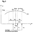
- Fig. 3 an example, actual time course of a vibrating transmission input speed or rotational speed ⁇ (t) over time is shown (reference numeral 30).
- the rotational speed ⁇ (t) is evaluated in each case.
- the clutch desired torque or the target allocation for the clutch travel is modulated, wherein the phase of this modulation is determined as a function of the phase of the rotational speed of the transmission input shaft.
- the actual local maximum of the rotational speed of the transmission input shaft is not given at the time t i , but rather at the time t roof . Accordingly, the actual local maximum of the rotational speed of the transmission input shaft is not ⁇ i , but ⁇ roof . As a result, there is an actual deviation between the phase of the rotational speed of the transmission input shaft and the phase of the modulated clutch travel.
- the vibration is caused by a modulation of the desired clutch travel and the target clutch torque.
- a second step the time deviation between the position of the local maximum of the transmission input rotational speed or rotational speed of the transmission input shaft determined in the first step and the actual position of this maximum of the transmission input rotational speed is determined.
- This deviation essentially corresponds to the deviation which is determined between the local maximum of the actual path and the actual local maximum of the transmission input rotational speed.
- the period of the modulated clutch travel is changed by the deviation ⁇ t for one period to achieve phase coincidence.
- Fig. 5 shows the steps of an exemplary method according to the invention in a schematic representation.
- step 40 it is determined and / or determined whether juddering vibrations are present in the drive train of a motor vehicle.
- step 42 a clutch travel modulation is started by which the juddering vibrations are to be counteracted.
- the modulation started in step 42 is such that a control alternates according to first and second time periods below.
- the control in first time periods is indicated by the step 44 and the control according to the second time intervals by the step 46.
- path mod Rampe_roch 1 Rampe_runter * k ausreg * A current * sin ⁇ pluck * t + ⁇ current .
- the Kupplungswegmodulation is thus carried out in response to a ramp function. This is in this example (ramp_high, 1, ramp_down).
- this ramp is started up at the beginning of the first time period and is shut down again at the end of the first time period.
- step 44 it is further provided that the amplitude A is actually updated at the sin zero crossing on the basis of the measured transmission input rotational speed.
- phase ⁇ currently remains constant.
- the first time segment may, for example, have a duration of 2 to 3 plucking periods.
- step 48 If this is the case, the method is ended in step 48. If this is not the case, after the step 44 has ended, the method is continued in step 46.
- step 46 the modulation of the clutch travel is interrupted so that the system can swing freely for a certain time. In particular, this is a time that is needed and / or used to re-determine the phase of the vibrations.
- step 44 the method is then continued in step 44.
- Fig. 6 shows the steps of an exemplary method according to the invention in a schematic representation.
- step 50 it is checked whether there are juddering vibrations in a drive train or it is determined that chattering vibrations are present in the drive train of a motor vehicle.
- step 42 it is begun to counteract these juddering vibrations, by a modulation of the torque transmittable by the clutch or according to the following context.
- M Mod M - k * ⁇ clutch disc / i corridor - ⁇ wheel
- this factor k is set up at the beginning ramped to its target value. This ramp is such that the target value of the factor k is reached after approximately one period of the juddering vibration.
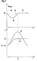
- Fig. 7 is in the upper half of a transmissible by a coupling device, modulated torque (curve 60) shown.
- curve 60 modulated torque
- Fig. 7 the angle of rotation of a predetermined drive train section shown (curve 62), which is given when no torque modulation is performed at a predetermined Rupfschwingung.
- curve 62 the angle of rotation of a predetermined drive train section
- the course 64 of the angle of rotation is shown, which occurs when the torque transmittable by the clutch is modulated according to the course 60.
- the juddering vibration has a substantially sinusoidal shape.
- the modulation of the transferable from the coupling device torque and the clutch travel is made so that the amplitude 66 of a first half-wave 68 is greater than the amplitude of a second half-wave or a non-existing wave 70th
- the profile of the half-wave 68 is set so that after the passage of the half-wave 68 or a corresponding Kupplungsweg- and / or torque modulation, the Rupfschwingung is substantially degraded.
- corresponding boundary conditions can be predetermined, based on which the course of the clutch torque modulation or the half-wave 68 is determined.
- the angle of rotation ⁇ 0 essentially corresponds to the angle of rotation which would be present if no juddering vibration were present in the drive train. So this is in particular a twist angle, which is due to a non-vibrating drive train load, if no self-excited vibrations are given.
- the curve 62 oscillates substantially by this angle of rotation ⁇ 0 .
- the value A ⁇ substantially corresponds to the amplitude exerted by the juddering vibration according to the curve 62 by the angle of rotation ⁇ 0 .
- the half-wave 64 corresponds to a function which can be expressed essentially as "- a * sin ( ⁇ * t).
- m 0 represents a constant
- ⁇ represents the angle of rotation
- d 2 ⁇ / dt represents the second time derivative of the angle of rotation
- conditions are defined in this design as an example, which should be given at the times "0" and "T / 2".
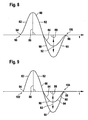
- the 8 and 9 show two exemplary courses of a sectionally modulated clutch torque over time.
- a modulated clutch torque can be used to counteract judder vibration in a powertrain.
- time axis used in the 8 and 9 is shown in vertical Direction is shifted.
- the course 80 of the modulated clutch torque has a first half-wave 82 as well as a second half-wave 84.
- the amplitude 86 of the first half-wave 82 is greater than the amplitude 88 of the second half-wave 84.
- This half-wave 90 is shown for comparison, although in another embodiment of the invention, the course of a second half-wave may also be as that of the half-wave 90th
- the designs according to the 8 and 9 differ in particular by the inlet and outlet of the respective half-waves 82, 84 of the vibrations.
- Fig. 8 is the inlet 94, which is given at the beginning of the period, essentially so that the time axis or a parallel to the time axis substantially in the form of a tangent to the inlet or the modulated clutch torque applies, as shown in the area 96.
- the modulated clutch torque runs according to Fig. 8 at the end of the period so that the time axis or a parallel to the time axis substantially in the form of a tangent to the outlet 98 and the modulated clutch torque applies, as shown in the area 100.
- Fig. 9 In the design according to Fig. 9 is the inlet 94 and the outlet 98 at the beginning or end of a period designed differently, in such a way that the time axis or an axis parallel thereto at an angle to the respective tangent in the region of the inlet 94 and outlet 98 is arranged. This is in areas 102 and 104 shown.
Landscapes
- Engineering & Computer Science (AREA)
- General Engineering & Computer Science (AREA)
- Mechanical Engineering (AREA)
- Physics & Mathematics (AREA)
- Fluid Mechanics (AREA)
- Aviation & Aerospace Engineering (AREA)
- Automation & Control Theory (AREA)
- Transportation (AREA)
- Acoustics & Sound (AREA)
- Hydraulic Clutches, Magnetic Clutches, Fluid Clutches, And Fluid Joints (AREA)
- Control Of Transmission Device (AREA)
- Soil Working Implements (AREA)
- Lenses (AREA)
- Inorganic Insulating Materials (AREA)
- Exhaust Silencers (AREA)
- Exhaust Gas After Treatment (AREA)
- Control Of Vehicle Engines Or Engines For Specific Uses (AREA)
Claims (65)
- Procédé pour diminuer les saccades dans un train d'entraînement d'un véhicule automobile, le train d'entraînement pouvant être sollicité par un système d'entraînement, par exemple un moteur à combustion interne, et présentant un système d'embrayage ainsi qu'un système de transmission, le procédé présentant les étapes qui consistent à :- déterminer la présence éventuelle de saccades et/ou constater la présence de saccades,- ajuster et en particulier ajuster automatiquement un système qui s'oppose aux saccades, ce système étant disposé dans le train d'entraînement ou étant accouplé à ce dernier de telle sorte qu'un ajustement de ce système modifie une valeur caractéristique de rotation, par exemple le couple de rotation ou la vitesse de rotation, associée à un composant du train d'entraînement et que cette modification modifie l'évolution temporelle des saccades,
caractérisé en ce que
le couple de rotation qui peut être transmis par le système d'embrayage et/ou le parcours d'embrayage sont modulés pour s'opposer aux saccades. - Procédé selon la revendication 1, caractérisé en ce que le couple de rotation qui peut être transmis par le système d'embrayage et/ou le parcours d'embrayage sont modulé de manière sinusoïdale.
- Procédé selon l'une des revendications précédentes, caractérisé en ce qu'il détermine au moins une valeur caractéristique prédéterminée de l'évolution temporelle des saccades et/ou une valeur caractéristique de rotation d'un composant du train d'entraînement, par exemple la vitesse de rotation à l'entrée de la transmission.
- Procédé selon l'une des revendications précédentes, caractérisé en ce que la phase, l'amplitude ou la durée de la période des saccades sont déterminées en fonction de la vitesse de rotation à l'entrée de la transmission.
- Procédé selon l'une des revendications précédentes, caractérisé en ce que la phase, l'amplitude ou la durée de la période de la modulation des vibrations du parcours d'embrayage et/ou du couple d'embrayage qui peut être transmis sont déterminées en fonction de la vitesse de rotation à l'entrée de la transmission.
- Procédé selon l'une des revendications 3 à 5, caractérisé en ce que la vitesse de rotation à l'entrée de la transmission est mesurée.
- Procédé selon l'une des revendications précédentes, caractérisé en ce que la vitesse de rotation à l'entrée de la transmission est mesurée de manière à délivrer des signaux de vitesse de rotation écartés les uns des autres dans le temps.
- Procédé selon l'une des revendications précédentes, caractérisé en ce que la période, la phase et/ou l'amplitude du couple de rotation modulé qui peut être transmis par le système d'embrayage, du parcours d'accouplement modulé et/ou des saccades sont déterminées en fonction d'au moins un extremum local et en particulier d'au moins un maximum local de la vitesse de rotation qui a été déterminée à l'entrée de la transmission.
- Procédé selon l'une des revendications précédentes, caractérisé en ce que la période, la phase et/ou l'amplitude du couple de rotation modulé qui peut être transmis par le système d'embrayage, du parcours d'accouplement modulé et/ou des saccades sont déterminées en fonction de la période, de la phase et/ou de l'amplitude qui ont été déterminées pour les saccades et/ou la vitesse de rotation à l'entrée de la transmission.
- Procédé selon l'une des revendications précédentes, caractérisé en ce que- dans une première étape, une première valeur caractéristique des saccades et/ou de l'évolution temporelle de la vitesse de rotation à l'entrée de la transmission sont déterminées au moyen d'une estimation, d'une mesure et/ou d'un calcul et- en ce que dans une deuxième étape, cette première valeur caractéristique est déterminée en fonction du résultat de la première étape pour améliorer et/ou vérifier la précision de la valeur caractéristique déterminée dans la première étape.
- Procédé selon la revendication 10, caractérisé en ce que la première valeur caractéristique est un extremum local de l'évolution temporelle des saccades et/ou de la vitesse de rotation à l'entrée de la transmission, ou la position dans le temps de cet extremum.
- Procédé selon l'une des revendications précédentes, caractérisé en ce que la vitesse de rotation à l'entrée de la transmission est mesurée et/ou évaluée de telle sorte que des signaux de vitesse de rotation situés à distance dans le temps soient délivrés, en ce que dans une première étape, la position dans le temps d'au moins un extremum local et en particulier d'un maximum local de ces valeurs de mesure est déterminée, cet extremum local étant en particulier celui qui est apparu en dernier lieu dans l'évolution temporelle, et en ce que dans une deuxième étape, la position effective d'un extremum local et en particulier d'un maximum local des saccades et/ou de la vitesse de rotation à l'entrée de la transmission est déterminée et/ou approchée de manière plus précise.
- Procédé selon la revendication 12, caractérisé en ce que la distance temporelle ou l'écart temporel entre l'extremum local, en particulier le maximum local, déterminé dans la première étape, et l'extremum local, en particulier le maximum local, déterminé dans la deuxième étape sont déterminés.
- Procédé selon l'une des revendications précédentes, caractérisé en ce que dans une première étape, le déphasage des saccades et/ou de l'évolution temporelle de la vitesse de rotation à l'entrée de la transmission est déterminé, et dans ce but on utilise en particulier un extremum local, en particulier un maximum local, déterminé dans la première étape, de la vitesse de rotation à l'entrée de la transmission qui est un extremum local situé à distance dans le temps des signaux de vitesse de rotation délivrés, en particulier des signaux de vitesse de rotation mesurés, et en ce que dans une deuxième étape, l'écart entre le déphasage déterminé dans la première étape et le déphasage effectif et/ou l'écart entre l'extremum local déterminé dans la première étape et l'extremum effectif sont déterminés.
- Procédé selon la revendication 14, caractérisé en ce que dans la détermination de l'écart, il tient compte du fait que la première étape a utilisé des signaux de vitesse de rotation situés à distance dans le temps et/ou des précisions de mesure qui découlent de la mesure de la vitesse de rotation effectuée dans la première étape.
- Procédé selon l'une des revendications 14 et 15, caractérisé en ce qu'une commande ou évaluation prédéterminée, en particulier une évaluation des valeurs de mesure, a lieu une fois pendant une fenêtre temporelle (Tint) prédéterminée dans laquelle une valeur de mesure ou une paire de valeurs de mesure prédéterminées d'une valeur caractéristique prédéterminée, par exemple la vitesse de rotation à l'entrée de la transmission, est fournie ou prise en compte dans cette fenêtre temporelle, cette situation étant prise en compte dans la détermination de l'écart.
- Procédé selon l'une des revendications 14 à 16, caractérisé en ce que la détermination de l'écart tient compte d'une éventuelle montée, essentiellement indépendante des saccades, de la vitesse de rotation à l'entrée de la transmission.
- Procédé selon l'une des revendications 13 à 17, caractérisé en ce que la détermination de l'écart utilise une valeur caractéristique, plusieurs valeurs caractéristiques ou toutes les valeurs caractéristiques parmi les suivantes :- une durée d'interruption Tint, la durée d'interruption Tint étant la durée d'une période au cours de laquelle une évaluation, en particulier une évaluation de la valeur de mesure de la vitesse angulaire de l'arbre d'entrée de la transmission, a lieu une fois et est préparée pour une valeur de mesure ou une paire de valeurs de mesure,- une médiane, la médiane indiquant le centre de gravité de paires prédéterminées de valeurs de mesure, en particulier d'attributions de la vitesse angulaire de l'arbre d'entrée de la transmission à des instants auxquels ces vitesses angulaires prévalent,- un instant (tmax) qui correspond à un extremum local, en particulier un maximum local, des signaux de vitesse de rotation ou de vitesse angulaire de l'arbre d'entrée de la transmission, délivrés à des intervalles de temps, qui ont été éventuellement constatés dans une première étape, ou qui leurs sont associés,- un extremum local, en particulier un maximum local (ωmax) qui correspond à des signaux délivrés à écart temporel de vitesse de rotation ou de vitesse angulaire de l'arbre d'entrée de la transmission et qui a éventuellement été constaté pendant une première étape,- l'amplitude (A) des saccades, et en particulier la dernière amplitude des saccades,- la fréquence des saccades (ωRupfen) / (2*π)),- l'augmentation totale (moyenne) de la vitesse angulaire de l'arbre d'entrée (B) de la transmission et- l'angle entre deux dents d'une sonde de position (ϕPuls).
- Procédé selon l'une des revendications 13 à 18, caractérisé en ce qu'un extremum local effectif, en particulier un maximum, de la vitesse angulaire de l'arbre d'entrée de la transmission est déterminé et/ou approché au moyen de l'écart déterminé, et/ou en ce que la phase effective de la vitesse angulaire de l'arbre d'entrée de la transmission qui se déplace également en oscillation pendant les saccades est déterminée.
- Procédé selon l'une des revendications 4, 5, 8, 9, 14, 19, caractérisé en ce que le déphasage déterminé dans la première étape, en particulier le déphasage de la vitesse angulaire de l'arbre d'entrée de la transmission et/ou des saccades, est utilisé d'abord pour la modulation du parcours de consigne de l'embrayage et/ou du couple de rotation qui peut être transmis par le système d'embrayage.
- Procédé selon l'une des revendications 4, 5, 8, 9, 14, 19, 20, caractérisé en ce que pour la modulation du parcours de consigne de l'embrayage et/ou du couple de rotation qui peut être transmis par le système d'embrayage, il utilise le déphasage de la vitesse de rotation, de la vitesse angulaire de l'arbre d'entrée dans la transmission et/ou des saccades, qui dans une deuxième étape est au moins approché du déphasage effectif vitesse de rotation à l'entrée de la transmission et/ou des saccades, et/ou l'écart.
- Procédé selon l'une des revendications 8 à 21, caractérisé en ce qu'il utilise l'écart temporel des positions temporelles d'un extremum, en particulier d'un maximum local, déterminé dans une première étape, de la vitesse de rotation à l'entrée de la transmission et une valeur d'un extremum local au moins approché de la position temporelle d'un extremum effectif, en particulier d'un maximum, pour modifier la durée de la période de la modulation du parcours de consigne d'embrayage et/ou du couple de rotation qui peut être transmis par le système d'embrayage, en particulier pour au moins approcher davantage le déphasage de ce parcours de consigne d'embrayage modulé et/ou du couple de rotation qui peut être transmis par le système d'embrayage du déphasage effectif de la vitesse de rotation de l'arbre d'entrée de la transmission.
- Procédé selon la revendication 22, caractérisé en ce que la durée de la période de la modulation du parcours de consigne de transmission et/ou du couple de rotation qui peut être transmis par le système d'embrayage est modifiée de manière à être prolongée ou raccourcie de cet écart pendant une période.
- Procédé selon l'une des revendications précédentes, caractérisé en ce que pour s'opposer aux saccades, le parcours de consigne d'embrayage et/ou le couple de rotation qui peut être transmis par le système d'embrayage sont modulés en fonction de l'extremum local, en particulier du maximum local, qui a été déterminé et/ou de sa position temporelle et/ou d'un écart déterminé.
- Procédé selon l'une des revendications précédentes, caractérisé en ce que cette modification de position est prédéterminée en fonction d'une fonction prédéterminée et en particulier d'une fonction temporelle qui présente une fonction de rampe.
- Procédé selon l'une des revendications précédentes, caractérisé en ce que la modification de la position du système s'oppose aux saccades dans des premiers intervalles de temps et en ce que la modification de la position du système est interrompue dans des deuxièmes intervalles de temps de telle sorte que le système puisse osciller librement pendant ces deuxièmes intervalles de temps.
- Procédé selon l'une des revendications 25 et 26, caractérisé en ce que le système est un système d'embrayage, le couple de rotation qui peut être transmis par le système d'embrayage et/ou le parcours d'embrayage, en particulier le parcours de consigne d'embrayage, étant modulés pour s'opposer aux saccades.
- Procédé selon l'une des revendications 25 à 27, caractérisé en ce que cette fonction en rampe présente une partie dans laquelle une rampe augmente d'une valeur initiale jusqu'à une certaine valeur, ainsi qu'un autre tronçon plus tardif dans lequel une rampe descend de cette valeur jusqu'à une valeur finale, en particulier à une valeur finale qui correspond à la valeur initiale.
- Procédé selon l'une des revendications 25 à 28, caractérisé en ce que cette fonction en rampe présente au moins une première partie dans laquelle une rampe monte d'une valeur initiale jusqu'à une certaine valeur, au moins une deuxième partie qui se raccorde à la première et au cours de laquelle la fonction en rampe est maintenue à cette valeur constante, ainsi qu'au moins une troisième partie qui se raccorde à la précédente et au cours de laquelle la fonction en rampe est amenée à descendre de cette valeur constante jusqu'à une valeur finale, en particulier une valeur finale qui correspond à la valeur initiale.
- Procédé selon la revendication 29, caractérisé en ce que la valeur constante est essentiellement égale à "un".
- Procédé selon l'une des revendications 25 à 30, caractérisé en ce que la valeur initiale et la valeur finale de la fonction en rampe sont toutes deux égales à "zéro".
- Procédé selon l'une des revendications 25 à 31, caractérisé en ce que le parcours d'embrayage modulé est déterminé en fonction d'un facteur de régulation et en particulier en fonction d'une constante de régulation.
- Procédé selon l'une des revendications 25 à 32, caractérisé en ce que le parcours d'embrayage modulé est déterminé en fonction de l'amplitude des saccades et en particulier en fonction de celle découverte en dernier lieu.
- Procédé selon l'une des revendications 25 à 33, caractérisé en ce que le parcours d'embrayage modulé est déterminé en fonction d'une fonction sinusoïdale, et en particulier en fonction d'une fonction sinusoïdale qui dépend de la fréquence des saccades, de la durée et/ou d'un déphasage déterminé entre les saccades et l'évolution de la modulation du parcours.
- Procédé selon la revendication 33 et la revendication 34, caractérisé en ce que le parcours d'embrayage modulé est déterminé en fonction d'une amplitude des saccades et en fonction d'une fonction sinusoïdale, cette amplitude étant actualisée lorsque la fonction sinusoïdale passe par zéro, en particulier en fonction de la vitesse de rotation à l'entrée de la transmission.
- Procédé selon l'une des revendications précédentes, caractérisé en ce que la modification de l'ajustement du dispositif et en particulier la modulation du parcours d'embrayage dans des premiers intervalles de temps alterne avec l'absence de modification de cet ajustement dans des deuxièmes intervalles de temps lorsque la présence de saccades est constatée, en particulier jusqu'à ce qu'il soit constaté que l'amplitude des saccades est inférieure à une valeur prédéterminée de débranchement.
- Procédé selon l'une des revendications 25 à 36, caractérisé en ce que la durée des premiers intervalles de temps est comprise entre une et cinq périodes des saccades et en particulier entre deux et trois périodes des saccades.
- Procédé selon l'une des revendications 25 à 37, caractérisé en ce que le parcours d'embrayage modulé est déterminé en fonction du déphasage entre les saccades et l'évolution de la modulation du parcours de consigne et/ou en fonction d'une fonction sinusoïdale qui dépend de ce déphasage, ce déphasage effectif étant actualisé dans des deuxièmes périodes de temps.
- Procédé selon l'une des revendications 25 à 38, caractérisé en ce que le parcours d'embrayage modulé est déterminé en fonction d'un déphasage entre les saccades et l'évolution de la modulation du parcours de consigne et/ou en fonction d'une fonction sinusoïdale qui dépend de ce déphasage, ce déphasage effectif étant considéré comme constant au cours de premières périodes de temps pour la modulation du parcours d'embrayage, en particulier en correspondance au moins partielle à une valeur qui a été déterminée pendant une deuxième période de temps précédente.
- Procédé selon la revendication 1, caractérisé en ce que ce train d'entraînement présente un système d'embrayage qui peut être utilisé en glissement, une modulation du couple de rotation qui peut être transmis par le système d'embrayage et/ou du parcours d'embrayage s'opposant aux saccades qui ont été déterminées, cette modulation étant telle qu'un couple de consigne d'embrayage modulé qui est déterminé comme étant la différence entre le couple d'embrayage non modulé et un produit est commandé, ce produit présentant en outre un premier facteur qui dépend de la vitesse angulaire d'un disque d'embrayage, de la vitesse angulaire d'un arbre d'entrée de la transmission, de la vitesse angulaire d'une roue du véhicule automobile et/ou d'un rapport de transmission associé au rapport engagé dans le système de transmission prévu dans le train d'entraînement, ce produit présentant un deuxième facteur qui est une constante de régulation, cette constante de régulation dépendant de valeurs caractéristiques du système oscillant du train d'entraînement et/ou de valeurs caractéristiques qui décrivent au moins implicitement la caractéristique de frottement du système d'embrayage.
- Procédé selon la revendication 1, caractérisé en ce que ce train d'entraînement présente un système d'embrayage qui peut être utilisé en glissement, une modulation du couple de rotation qui peut être transmis par le système d'embrayage et/ou du parcours d'embrayage s'opposant aux saccades qui ont été déterminées, cette modulation étant telle qu'un couple de consigne d'embrayage modulé qui est déterminé comme étant la différence entre le couple d'embrayage non modulé et un produit est commandé, ce produit présentant en outre un premier facteur qui dépend de la vitesse angulaire d'un disque d'embrayage, de la vitesse angulaire d'un arbre d'entrée de la transmission, de la vitesse angulaire d'une roue du véhicule automobile et/ou d'un rapport de transmission associé au rapport engagé dans le système de transmission prévu dans le train d'entraînement, ce produit présentant un deuxième facteur qui est une constante de régulation, cette constante de régulation dépendant du couple de consigne d'embrayage et/ou d'un couple nominal d'embrayage qui est déterminé en posant l'hypothèse d'une valeur de frottement nominale, et/ou d'une fonction d'un glissement moyen.
- Procédé selon l'une des revendications 40 ou 41, caractérisé en ce que la constante de régulation dépend d'une fonction qui décrit comment la valeur de frottement du dispositif d'embrayage varie en fonction du glissement du système d'embrayage et/ou de la dérivée par rapport au temps de cette fonction.
- Procédé selon l'une des revendications 40 à 42, caractérisé en ce que la constante de régulation dépend de la période T des saccades.
- Procédé selon l'une des revendications 40 à 43, caractérisé en ce que la constante de régulation dépend du couple d'inertie d'un disque d'embrayage et/ou de l'entrée de la transmission.
- Procédé selon l'une des revendications 40 à 44, caractérisé en ce que la constante de régulation dépend d'une valeur nominale du frottement du système d'embrayage.
- Procédé selon l'une des revendications 40 à 45, caractérisé en ce que la constante de régulation dépend du quotient de deux amplitudes successives des saccades, en particulier du logarithme de ce quotient.
- Procédé selon l'une des revendications 25, 28, 29, 31 ou 44, caractérisé en ce que la valeur cible de la rampe s'établit sensiblement au cours d'une période des saccades.
- Procédé selon la revendication 1, caractérisé en ce qu'un système d'embrayage qui peut fonctionner en glissement est disposé dans ce train d'entraînement, et dans lequel une modulation du couple de rotation qui peut être transmis par le système d'embrayage et/ou du parcours d'embrayage s'oppose aux saccades déterminées, cette modulation étant telle que la modulation est exécutée en différentes parties selon des caractéristiques différentes.
- Procédé selon la revendication 1, caractérisé en ce qu'un système d'embrayage qui peut fonctionner en glissement est disposé dans ce train d'entraînement, et dans lequel une modulation du couple de rotation qui peut être transmis par le système d'embrayage et/ou du parcours d'embrayage s'oppose aux saccades déterminées, cette modulation étant telle qu'elle est configurée de manière oscillante et présente une première demi-onde (68, 82) ainsi qu'éventuellement une deuxième demi-onde (70, 84), l'amplitude (66, 86) de la première demi-onde étant plus grande que l'amplitude (88) de la deuxième demi-onde (70, 84).
- Procédé selon la revendication 49, caractérisé en ce que la modulation est interrompue ou arrêtée après la deuxième demi-onde (70, 84) et en ce que la phase des saccades est déterminée, en particulier au moyen d'au moins un extremum local, par exemple un maximum local, des saccades et/ou de la vitesse de rotation à l'entrée de la transmission.
- Procédé selon la revendication 49, caractérisé en ce que l'amplitude (88) de la deuxième demi-onde (70, 84) est égale à "zéro".
- Procédé selon la revendication 50, caractérisé en ce que la modulation est interrompue ou terminée après la première demi-onde (68, 82) et en ce que la phase des saccades est déterminée, en particulier au moyen d'au moins un extremum local, par exemple un maximum local, des saccades et/ou de la vitesse de rotation à l'entrée de la transmission.
- Procédé selon l'une des revendications 49 à 52, caractérisé en ce que la première demi-onde (68, 82) et/ou la deuxième demi-onde (70, 84) sont des demi-ondes (68, 70, 82, 84) d'une oscillation sinusoïdale.
- Procédé selon l'une des revendications précédentes, caractérisé en ce que la modulation est lancée à un décalage de phase par rapport aux saccades.
- Procédé selon la revendication 54, caractérisé en ce que la modulation est lancée lorsqu'un extremum local, en particulier un maximum local, des saccades a été constaté.
- Procédé selon l'une des revendications précédentes, caractérisé en ce que la modulation est configurée de telle sorte qu'une tangente de l'évolution temporelle de la modulation du couple de rotation transmis et/ou du parcours d'embrayage au début et/ou à la fin d'une demi-onde (68, 70) est essentiellement parallèle à l'axe du temps.
- Procédé selon la revendication 1, caractérisé en ce qu'un système d'embrayage qui peut fonctionner en glissement est disposé dans ce train d'entraînement et en ce qu'une modulation du couple de rotation qui peut être transmis par le système d'embrayage et/ou du parcours d'embrayage s'oppose aux saccades déterminées, cette modulation étant telle que la modulation est déterminée en fonction des saccades, de valeurs caractéristiques qui décrivent les saccades et/ou d'une fonction qui décrit les saccades, ainsi qu'en fonction de conditions aux limites prédéterminées.
- Procédé selon la revendication 57, caractérisé en ce que les saccades sont décrites en particulier en fonction de l'angle de torsion d'une partie prédéterminée du train d'entraînement.
- Procédé selon l'une des revendications précédentes, caractérisé en ce que l'évolution de la modulation est prédéterminée en fonction de variables et en ce que ces variables sont définies au moins en partie à l'aide de conditions aux limites.
- Procédé selon l'une des revendications 57 à 59, caractérisé en ce qu'une condition aux limites est que l'angle de torsion à l'instant "zéro" correspond à la différence entre l'angle de torsion qui aurait prévalu dans un cas de sollicitation donné, compte non tenu des saccades, et l'amplitude angulaire des saccades.
- Procédé selon l'une des revendications 57 à 60, caractérisé en ce qu'une condition aux limites est que la dérivée temporelle de l'angle de torsion à l'instant "zéro" est égale à "zéro".
- Procédé selon l'une des revendications 57 à 61, caractérisé en ce qu'une condition aux limites est que l'angle de torsion à l'instant de la durée de la demi-période des saccades correspond à l'angle de torsion qui aurait prévalu dans un cas de sollicitation donné, compte non tenu des saccades.
- Procédé selon l'une des revendications 57 à 62, caractérisé en ce qu'une condition aux limites est que la dérivée temporelle de l'angle de torsion à l'instant de la demi-durée d'une période des saccades est égale à "zéro".
- Procédé selon l'une des revendications 57 à 63, caractérisé en ce que la durée de la période de la modulation du couple de rotation qui peut être transmis par le système d'embrayage et/ou du parcours d'embrayage correspond à la moitié de la durée d'une période des saccades.
- Procédé selon l'une des revendications 57 à 64, caractérisé en ce que le couple de rotation qui peut être transmis par le système d'embrayage et/ou le parcours d'embrayage a une valeur modulée selon une fonction a*sin(ω*t), a étant un facteur, ω le produit par 2π de la fréquence des oscillations de la modulation et t représentant le temps.
Applications Claiming Priority (3)
| Application Number | Priority Date | Filing Date | Title |
|---|---|---|---|
| DE10242225 | 2002-09-12 | ||
| DE10242225 | 2002-09-12 | ||
| PCT/DE2003/002989 WO2004027285A1 (fr) | 2002-09-12 | 2003-09-10 | Procede pour reduire des vibrations de grippage |
Publications (2)
| Publication Number | Publication Date |
|---|---|
| EP1540201A1 EP1540201A1 (fr) | 2005-06-15 |
| EP1540201B1 true EP1540201B1 (fr) | 2010-12-15 |
Family
ID=32009817
Family Applications (1)
| Application Number | Title | Priority Date | Filing Date |
|---|---|---|---|
| EP03753283A Revoked EP1540201B1 (fr) | 2002-09-12 | 2003-09-10 | Procede pour reduire des vibrations de grippage |
Country Status (10)
| Country | Link |
|---|---|
| US (1) | US7299120B2 (fr) |
| EP (1) | EP1540201B1 (fr) |
| JP (1) | JP2005538327A (fr) |
| KR (1) | KR101290352B1 (fr) |
| CN (1) | CN1682042B (fr) |
| AT (1) | ATE491900T1 (fr) |
| AU (1) | AU2003271524A1 (fr) |
| BR (1) | BR0306321A (fr) |
| DE (2) | DE10392932D2 (fr) |
| WO (1) | WO2004027285A1 (fr) |
Cited By (1)
| Publication number | Priority date | Publication date | Assignee | Title |
|---|---|---|---|---|
| DE102015205914A1 (de) | 2015-04-01 | 2016-10-06 | Volkswagen Aktiengesellschaft | Verfahren zum Kontrollieren von Rupfschwingungen in einem Antriebsstrang eines Kraftfahrzeugs, Schaltgetriebe und Antriebsstrang |
Families Citing this family (41)
| Publication number | Priority date | Publication date | Assignee | Title |
|---|---|---|---|---|
| JP3846438B2 (ja) * | 2003-03-17 | 2006-11-15 | トヨタ自動車株式会社 | 車両用摩擦係合装置の制御装置 |
| JP4525613B2 (ja) * | 2006-02-28 | 2010-08-18 | トヨタ自動車株式会社 | 車両用動力伝達装置の制御装置 |
| DE102006009608A1 (de) * | 2006-03-02 | 2007-09-06 | Zf Friedrichshafen Ag | Verfahren zur Steuerung bzw. Regelung einer drehmomentführenden Kupplung |
| DE102007006803B4 (de) | 2006-03-08 | 2019-04-18 | Schaeffler Technologies AG & Co. KG | Verfahren und Vorrichtung zum Vermindern von Rupfschwingungen in einem Kraftfahrzeugantriebsstrang |
| EP1832774A2 (fr) | 2006-03-08 | 2007-09-12 | LuK Lamellen und Kupplungsbau Beteiligungs KG | Procédé et dispositif destinés à réduire les vibrations dans la transmission d'un véhicule automobile |
| DE102006022692B4 (de) * | 2006-05-16 | 2008-07-10 | Volkswagen Ag | Vorrichtung und Verfahren zur Aktivierung und Deaktivierung von Funktionen eines Fahrzeugs |
| US9174645B2 (en) * | 2007-05-17 | 2015-11-03 | Fca Us Llc | Systems and methods for detecting and reducing high driveline torsional levels in automobile transmissions |
| WO2009003454A2 (fr) * | 2007-07-05 | 2009-01-08 | Luk Lamellen Und Kupplungsbau Beteiligungs Kg | Procédé et dispositif de régulation du glissement d'un embrayage de véhicule |
| US20090090592A1 (en) * | 2007-10-05 | 2009-04-09 | Gm Global Technology Operations, Inc. | High-Frequency Anti-Lock Clutch System and Method |
| FR2923566B1 (fr) * | 2007-11-09 | 2010-03-12 | Peugeot Citroen Automobiles Sa | Procede et dispositif de commande d'un embrayage d'une transmission a boite de vitesses mecanique pilotee permettant d'eviter les oscillations en phase de decollage |
| DE102008035556A1 (de) * | 2008-07-30 | 2010-02-04 | Bayerische Motoren Werke Aktiengesellschaft | Steuer- oder Regelsystem für ein zumindest zeitweise vierradgetriebenes Kraftfahrzeug |
| DE102008041884A1 (de) * | 2008-09-09 | 2010-03-11 | Zf Friedrichshafen Ag | Verfahren zum Erkennen und Kompensieren von Schwingungen bei einem Fahrzeug |
| US7942068B2 (en) * | 2009-03-11 | 2011-05-17 | Ge Infrastructure Sensing, Inc. | Method and system for multi-path ultrasonic flow rate measurement |
| US8682532B2 (en) | 2011-07-22 | 2014-03-25 | Honda Motor Co., Ltd. | Vehicle including friction control device and methods |
| DE102011114303A1 (de) * | 2011-09-23 | 2012-11-08 | Audi Ag | Verfahren zum Verringern einer mechanischen Belastung mindestens einer Komponente des Antriebsstrangs eines Kraftfahrzeugs sowie entsprechendes Kraftfahrzeug |
| DE102011084548A1 (de) * | 2011-10-14 | 2013-04-18 | Robert Bosch Gmbh | Aktive Dämpfungsregelung für ein Elektro- oder Hybridfahrzeug |
| DE112013001982A5 (de) * | 2012-04-11 | 2015-01-08 | Schaeffler Technologies Gmbh & Co. Kg | Verfahren zur Verminderung von Rupfschwingungen |
| US8961364B2 (en) * | 2012-05-07 | 2015-02-24 | Ford Global Technologies, Llc | Method and system to manage driveline oscillations with clutch pressure control |
| CN105074250B (zh) * | 2013-04-11 | 2018-01-12 | 舍弗勒技术股份两合公司 | 用于减小机动车辆的动力传动系中的摩擦离合器的拉拔振动的方法 |
| US9925972B2 (en) * | 2013-06-21 | 2018-03-27 | Ford Global Technologies, Llc | Method and system for reducing driveline NVH |
| JP6201210B2 (ja) | 2013-09-24 | 2017-09-27 | 日立オートモティブシステムズ株式会社 | 電動車両の制御装置及び電動車両の制御方法 |
| US9284903B2 (en) * | 2013-12-30 | 2016-03-15 | GM Global Technology Operations LLC | System and method for adjusting engine speed and/or engine load to improve fuel economy without causing vehicle vibration that is perceivable by a vehicle occupant |
| DE102014203804B4 (de) | 2014-03-03 | 2025-11-06 | Schaeffler Technologies AG & Co. KG | Dämpfung einer Rupfschwingung |
| DE112015001832A5 (de) * | 2014-04-16 | 2016-12-29 | Schaeffler Technologies AG & Co. KG | Verfahren zur Auslegung eines Softwaretilgers einer Kupplungssteuerung und Softwaretilger zur Dämpfung von Rupfschwingungen |
| JP6070630B2 (ja) * | 2014-05-16 | 2017-02-01 | トヨタ自動車株式会社 | 四輪駆動車両の制御装置 |
| KR101601445B1 (ko) * | 2014-07-04 | 2016-03-09 | 현대자동차주식회사 | 차량의 건식클러치 제어방법 |
| KR101601446B1 (ko) * | 2014-07-04 | 2016-03-09 | 현대자동차주식회사 | 차량의 건식클러치 제어방법 |
| DE102014222457A1 (de) | 2014-11-04 | 2016-05-04 | Schaeffler Technologies AG & Co. KG | Verfahren zur Ermittlung eines Übertragungsverhaltens eines Antriebsstrangs |
| DE102014224030A1 (de) * | 2014-11-25 | 2016-05-25 | Volkswagen Aktiengesellschaft | Verfahren zur Erkennung eines Längsruckelns eines Kraftfahrzeugs |
| DE102015002296B4 (de) | 2015-02-24 | 2020-02-20 | Audi Ag | Verfahren zum Betreiben eines Antriebsstrangs für ein Kraftfahrzeug sowie entsprechender Antriebsstrang |
| US9506509B1 (en) | 2015-09-10 | 2016-11-29 | Ford Global Technologies, Llc | Clutch control using dither |
| JP6587487B2 (ja) * | 2015-09-30 | 2019-10-09 | 倉敷化工株式会社 | アクティブ除振装置及びそのセンサの設置方法 |
| US10053109B2 (en) | 2016-02-26 | 2018-08-21 | Honda Motor Co., Ltd. | Systems and methods for controlling a vehicle including friction control device |
| KR102359278B1 (ko) | 2017-08-31 | 2022-02-08 | 주식회사 대동 | 캐빈형 작업차 |
| KR102645379B1 (ko) * | 2018-12-27 | 2024-03-07 | 현대트랜시스 주식회사 | 차량의 클러치 제어시스템 및 제어방법 |
| DE102019204402A1 (de) * | 2019-03-28 | 2020-10-01 | Zf Friedrichshafen Ag | Bestimmung eines Steuerstroms für ein Stetigventil |
| KR102719115B1 (ko) * | 2019-06-28 | 2024-10-17 | 현대자동차주식회사 | 차량의 클러치 제어장치 |
| DE102020206309B4 (de) | 2020-05-19 | 2024-01-25 | Magna Pt B.V. & Co. Kg | Vorrichtung und Verfahren zum Erkennen und Reduzieren einer Störschwingung bei einem Fahrzeug |
| KR20230123187A (ko) | 2022-02-16 | 2023-08-23 | 현대자동차주식회사 | 인공지능 활용 차량 저더 진단 방법 및 모바일 기반 gds |
| KR20240022014A (ko) | 2022-08-10 | 2024-02-20 | 현대자동차주식회사 | 실시간 저더 진단 기반 차량 클러치 수명 예측 방법 및 차량 저단 실시간 진단 시스템 |
| CN120868188B (zh) * | 2025-09-24 | 2025-12-09 | 嘉兴大学 | 一种行星排同轴减速器振动噪声优化方法 |
Family Cites Families (25)
| Publication number | Priority date | Publication date | Assignee | Title |
|---|---|---|---|---|
| US471376A (en) * | 1892-03-22 | Car-coupling | ||
| US575913A (en) * | 1897-01-26 | Paper box | ||
| JPS5712128A (en) * | 1980-06-24 | 1982-01-22 | Mitsubishi Motors Corp | Torque transmission apparatus |
| DE3404154A1 (de) * | 1984-02-07 | 1985-08-14 | Daimler-Benz Ag, 7000 Stuttgart | Regeleinrichtung, die eine gemischbildungsanlage einer brennkraftmaschine eines kraftfahrzeuges beeinflusst |
| JPH02135724U (fr) * | 1989-04-18 | 1990-11-13 | ||
| DE4009792C2 (de) * | 1990-03-27 | 1995-08-31 | Daimler Benz Ag | Verfahren zur Unterdrückung von Schwingungen im Antriebsstrang eines Kraftfahrzeugs |
| JPH0480934U (fr) * | 1990-11-22 | 1992-07-14 | ||
| DE4306277C2 (de) * | 1993-03-01 | 2000-11-02 | Leibinger Gmbh | Operationsmarkierungswerkzeug |
| DE59305651D1 (de) * | 1993-10-27 | 1997-04-10 | Siemens Ag | Verfahren zum Unterdrücken von Schwingungen des Antriebsstranges eines Kraftfahrzeugs durch Zündzeitpunktsteuerung |
| DE19536320C2 (de) * | 1995-09-29 | 1997-07-17 | Fichtel & Sachs Ag | Verfahren und Vorrichtung zum Ändern eines Nutzmoments in einem Antriebsstrang eines Kraftfahrzeugs |
| CN1071644C (zh) * | 1996-05-24 | 2001-09-26 | 杨泰和 | 分配式差动耦合复合动力系统 |
| DE19628789C2 (de) * | 1996-07-17 | 1998-05-28 | Daimler Benz Ag | Automatisch gesteuerte Kupplung |
| JPH10103388A (ja) * | 1996-09-26 | 1998-04-21 | Unisia Jecs Corp | 車両用クラッチの制御装置 |
| JPH10213155A (ja) * | 1997-01-31 | 1998-08-11 | Unisia Jecs Corp | クラッチの制御装置 |
| JPH11351276A (ja) * | 1998-06-05 | 1999-12-24 | Toyota Motor Corp | 摩擦クラッチ機構の制振装置 |
| AU1963600A (en) | 1998-11-18 | 2000-06-05 | Luk Lamellen Und Kupplungsbau Gmbh | Method and control device for controlling a motor vehicle fitted with a manual gearbox |
| US8498693B2 (en) * | 1999-02-02 | 2013-07-30 | Senorx, Inc. | Intracorporeal marker and marker delivery device |
| US20090216118A1 (en) * | 2007-07-26 | 2009-08-27 | Senorx, Inc. | Polysaccharide markers |
| DE19928516A1 (de) * | 1999-06-22 | 2000-12-28 | Bosch Gmbh Robert | Verfahren und Vorrichtung zur Steuerung der Antriebseinheit eines Fahrzeugs |
| DE19949449B4 (de) * | 1999-10-14 | 2005-11-03 | Daimlerchrysler Ag | Verfahren zur Dämpfung von Ruckelschwingungen |
| EP1173098A4 (fr) * | 2000-01-26 | 2004-10-13 | Heartport Inc | Inciseur vasculaire et procede |
| DE10035521B4 (de) * | 2000-07-21 | 2006-04-20 | Zf Sachs Ag | Verfahren und Vorrichtung zur Reduzierung von Lastwechselschwingungen im Antriebsstrang eines Kraftfahrzeugs |
| US6394965B1 (en) * | 2000-08-15 | 2002-05-28 | Carbon Medical Technologies, Inc. | Tissue marking using biocompatible microparticles |
| US7329414B2 (en) * | 2002-05-03 | 2008-02-12 | Biopsy Sciences, Llc | Biodegradable polymer for marking tissue and sealing tracts |
| US7988199B2 (en) * | 2007-09-24 | 2011-08-02 | Michele Welsh | Safety skin applique kit for identification of lost persons |
-
2003
- 2003-09-10 BR BR0306321-6A patent/BR0306321A/pt not_active IP Right Cessation
- 2003-09-10 KR KR1020057004203A patent/KR101290352B1/ko not_active Expired - Fee Related
- 2003-09-10 AT AT03753283T patent/ATE491900T1/de active
- 2003-09-10 DE DE10392932T patent/DE10392932D2/de not_active Expired - Fee Related
- 2003-09-10 AU AU2003271524A patent/AU2003271524A1/en not_active Abandoned
- 2003-09-10 WO PCT/DE2003/002989 patent/WO2004027285A1/fr not_active Ceased
- 2003-09-10 CN CN038217252A patent/CN1682042B/zh not_active Expired - Fee Related
- 2003-09-10 EP EP03753283A patent/EP1540201B1/fr not_active Revoked
- 2003-09-10 DE DE50313330T patent/DE50313330D1/de not_active Expired - Lifetime
- 2003-09-10 JP JP2004536850A patent/JP2005538327A/ja active Pending
-
2005
- 2005-03-11 US US10/906,907 patent/US7299120B2/en not_active Expired - Fee Related
Cited By (1)
| Publication number | Priority date | Publication date | Assignee | Title |
|---|---|---|---|---|
| DE102015205914A1 (de) | 2015-04-01 | 2016-10-06 | Volkswagen Aktiengesellschaft | Verfahren zum Kontrollieren von Rupfschwingungen in einem Antriebsstrang eines Kraftfahrzeugs, Schaltgetriebe und Antriebsstrang |
Also Published As
| Publication number | Publication date |
|---|---|
| EP1540201A1 (fr) | 2005-06-15 |
| US20050189192A1 (en) | 2005-09-01 |
| ATE491900T1 (de) | 2011-01-15 |
| DE50313330D1 (de) | 2011-01-27 |
| DE10392932D2 (de) | 2005-04-07 |
| AU2003271524A1 (en) | 2004-04-08 |
| KR20050057304A (ko) | 2005-06-16 |
| JP2005538327A (ja) | 2005-12-15 |
| WO2004027285A1 (fr) | 2004-04-01 |
| CN1682042A (zh) | 2005-10-12 |
| KR101290352B1 (ko) | 2013-07-26 |
| US7299120B2 (en) | 2007-11-20 |
| BR0306321A (pt) | 2004-09-28 |
| CN1682042B (zh) | 2011-01-26 |
Similar Documents
| Publication | Publication Date | Title |
|---|---|---|
| EP1540201B1 (fr) | Procede pour reduire des vibrations de grippage | |
| DE112008001539B4 (de) | Verfahren und Vorrichtung zum Regeln des Schlupfes einer Fahrzeugkupplung | |
| WO2003019029A1 (fr) | Procede et systeme de commande d'un embrayage a friction automatise dispose entre un moteur et une boite de vitesses d'un vehicule | |
| EP2016312A1 (fr) | Procédé et dispositif pour adapter la commande des embrayages d'une transmission à double embrayage | |
| EP2379390B1 (fr) | Procédé et dispositif pour le fonctionnement d'un véhicule hybride | |
| DE10323567A1 (de) | Verfahren und Vorrichtung zum Modulieren des von einer Fahrzeugkupplung übertragenen Moments | |
| DE19536320C2 (de) | Verfahren und Vorrichtung zum Ändern eines Nutzmoments in einem Antriebsstrang eines Kraftfahrzeugs | |
| EP1642051B1 (fr) | Procede de commande et de regulation d'un frein d'engrenage dans une boite de vitesses automatique d'un vehicule automobile | |
| EP3662183A1 (fr) | Procédé de fonctionnement d'une chaîne cinématique d'un véhicule à moteur, en particulier d'un véhicule automobile | |
| DE102011102400A1 (de) | Verfahren zur Glättung eines Getriebeeingangswellendrehzahlsignales eines Getriebes | |
| DE10057054B4 (de) | Verfahren zum Erkennen von Schwingungen | |
| DE10192542B4 (de) | Verfahren und Steuerungseinrichtung zur Steuerung von Betriebskennwerten eines Antriebsstranges | |
| WO2016141940A1 (fr) | Procédé d'adaptation d'un modèle d'embrayage d'un embrayage automatisé par adaptation d'un coefficient de frottement de l'embrayage | |
| DE102013112967A1 (de) | Verfahren zum Steuern eines Verbrennungsmotors | |
| DE10026332A1 (de) | Verfahren zur koordinierten Steuerung eines Fahrzeugmotors und einer Kupplung mittels einer Antriebsstrangsteuerung während eines Wechsels einer Getriebeübersetzung | |
| EP1617058A2 (fr) | Procédé de régulation de la stratégie de démarrage de moteurs à combustion | |
| DE10301869A1 (de) | Verfahren zur Schwingungsdämpfung eines Antriebsstrangs und Antriebsstrang | |
| DE102010024938A1 (de) | Verfahren zur Regelung eines Antriebsstrangs mit automatischer Reibungskupplung und Antriebsstrang hierzu | |
| DE102018106167B4 (de) | Verfahren zur Ansteuerung eines Hybridantriebsstranges eines Fahrzeugs | |
| WO2019105946A1 (fr) | Procédé de détermination de la pression de contact requise d'un frein | |
| DE102009050387A1 (de) | System und Verfahren zur Ermittlung einer Torsionswinkel-Änderung eines Antriebsstrangs | |
| DE102006045858A1 (de) | Verfahren zur Steuerung einer automatisierten Kupplung | |
| DE102005004224A1 (de) | Verfahren zur Steuerung des Anfahrvorganges in einem Antriebsstrang eines Fahrzeuges | |
| EP1188601B1 (fr) | Méthode de commande et de limitation du couple d'entrée d'une boíte de vitesses pendant le démarrage d'un véhicule | |
| EP1578635A1 (fr) | Procede et dispositif pour commander un embrayage a l'interieur de l'ensemble transmission d'un vehicule automobile |
Legal Events
| Date | Code | Title | Description |
|---|---|---|---|
| PUAI | Public reference made under article 153(3) epc to a published international application that has entered the european phase |
Free format text: ORIGINAL CODE: 0009012 |
|
| 17P | Request for examination filed |
Effective date: 20050412 |
|
| AK | Designated contracting states |
Kind code of ref document: A1 Designated state(s): AT BE BG CH CY CZ DE DK EE ES FI FR GB GR HU IE IT LI LU MC NL PT RO SE SI SK TR |
|
| AX | Request for extension of the european patent |
Extension state: AL LT LV MK |
|
| DAX | Request for extension of the european patent (deleted) | ||
| 17Q | First examination report despatched |
Effective date: 20070205 |
|
| GRAP | Despatch of communication of intention to grant a patent |
Free format text: ORIGINAL CODE: EPIDOSNIGR1 |
|
| RIC1 | Information provided on ipc code assigned before grant |
Ipc: F16F 15/00 20060101AFI20100602BHEP |
|
| GRAS | Grant fee paid |
Free format text: ORIGINAL CODE: EPIDOSNIGR3 |
|
| GRAA | (expected) grant |
Free format text: ORIGINAL CODE: 0009210 |
|
| AK | Designated contracting states |
Kind code of ref document: B1 Designated state(s): AT BE BG CH CY CZ DE DK EE ES FI FR GB GR HU IE IT LI LU MC NL PT RO SE SI SK TR |
|
| REG | Reference to a national code |
Ref country code: GB Ref legal event code: FG4D Free format text: NOT ENGLISH Ref country code: CH Ref legal event code: EP |
|
| REG | Reference to a national code |
Ref country code: IE Ref legal event code: FG4D |
|
| REF | Corresponds to: |
Ref document number: 50313330 Country of ref document: DE Date of ref document: 20110127 Kind code of ref document: P |
|
| REG | Reference to a national code |
Ref country code: NL Ref legal event code: VDEP Effective date: 20101215 |
|
| PG25 | Lapsed in a contracting state [announced via postgrant information from national office to epo] |
Ref country code: SE Free format text: LAPSE BECAUSE OF FAILURE TO SUBMIT A TRANSLATION OF THE DESCRIPTION OR TO PAY THE FEE WITHIN THE PRESCRIBED TIME-LIMIT Effective date: 20101215 Ref country code: CY Free format text: LAPSE BECAUSE OF FAILURE TO SUBMIT A TRANSLATION OF THE DESCRIPTION OR TO PAY THE FEE WITHIN THE PRESCRIBED TIME-LIMIT Effective date: 20101215 Ref country code: NL Free format text: LAPSE BECAUSE OF FAILURE TO SUBMIT A TRANSLATION OF THE DESCRIPTION OR TO PAY THE FEE WITHIN THE PRESCRIBED TIME-LIMIT Effective date: 20101215 Ref country code: BG Free format text: LAPSE BECAUSE OF FAILURE TO SUBMIT A TRANSLATION OF THE DESCRIPTION OR TO PAY THE FEE WITHIN THE PRESCRIBED TIME-LIMIT Effective date: 20110315 Ref country code: FI Free format text: LAPSE BECAUSE OF FAILURE TO SUBMIT A TRANSLATION OF THE DESCRIPTION OR TO PAY THE FEE WITHIN THE PRESCRIBED TIME-LIMIT Effective date: 20101215 Ref country code: SI Free format text: LAPSE BECAUSE OF FAILURE TO SUBMIT A TRANSLATION OF THE DESCRIPTION OR TO PAY THE FEE WITHIN THE PRESCRIBED TIME-LIMIT Effective date: 20101215 |
|
| REG | Reference to a national code |
Ref country code: IE Ref legal event code: FD4D |
|
| PG25 | Lapsed in a contracting state [announced via postgrant information from national office to epo] |
Ref country code: PT Free format text: LAPSE BECAUSE OF FAILURE TO SUBMIT A TRANSLATION OF THE DESCRIPTION OR TO PAY THE FEE WITHIN THE PRESCRIBED TIME-LIMIT Effective date: 20110415 Ref country code: GR Free format text: LAPSE BECAUSE OF FAILURE TO SUBMIT A TRANSLATION OF THE DESCRIPTION OR TO PAY THE FEE WITHIN THE PRESCRIBED TIME-LIMIT Effective date: 20110316 Ref country code: EE Free format text: LAPSE BECAUSE OF FAILURE TO SUBMIT A TRANSLATION OF THE DESCRIPTION OR TO PAY THE FEE WITHIN THE PRESCRIBED TIME-LIMIT Effective date: 20101215 Ref country code: CZ Free format text: LAPSE BECAUSE OF FAILURE TO SUBMIT A TRANSLATION OF THE DESCRIPTION OR TO PAY THE FEE WITHIN THE PRESCRIBED TIME-LIMIT Effective date: 20101215 Ref country code: IE Free format text: LAPSE BECAUSE OF FAILURE TO SUBMIT A TRANSLATION OF THE DESCRIPTION OR TO PAY THE FEE WITHIN THE PRESCRIBED TIME-LIMIT Effective date: 20101215 Ref country code: ES Free format text: LAPSE BECAUSE OF FAILURE TO SUBMIT A TRANSLATION OF THE DESCRIPTION OR TO PAY THE FEE WITHIN THE PRESCRIBED TIME-LIMIT Effective date: 20110326 |
|
| PG25 | Lapsed in a contracting state [announced via postgrant information from national office to epo] |
Ref country code: SK Free format text: LAPSE BECAUSE OF FAILURE TO SUBMIT A TRANSLATION OF THE DESCRIPTION OR TO PAY THE FEE WITHIN THE PRESCRIBED TIME-LIMIT Effective date: 20101215 Ref country code: RO Free format text: LAPSE BECAUSE OF FAILURE TO SUBMIT A TRANSLATION OF THE DESCRIPTION OR TO PAY THE FEE WITHIN THE PRESCRIBED TIME-LIMIT Effective date: 20101215 |
|
| PLBI | Opposition filed |
Free format text: ORIGINAL CODE: 0009260 |
|
| PLAX | Notice of opposition and request to file observation + time limit sent |
Free format text: ORIGINAL CODE: EPIDOSNOBS2 |
|
| 26 | Opposition filed |
Opponent name: ZF FRIEDRICHSHAFEN AG Effective date: 20110915 |
|
| PG25 | Lapsed in a contracting state [announced via postgrant information from national office to epo] |
Ref country code: DK Free format text: LAPSE BECAUSE OF FAILURE TO SUBMIT A TRANSLATION OF THE DESCRIPTION OR TO PAY THE FEE WITHIN THE PRESCRIBED TIME-LIMIT Effective date: 20101215 |
|
| REG | Reference to a national code |
Ref country code: DE Ref legal event code: R026 Ref document number: 50313330 Country of ref document: DE Effective date: 20110915 |
|
| PG25 | Lapsed in a contracting state [announced via postgrant information from national office to epo] |
Ref country code: IT Free format text: LAPSE BECAUSE OF FAILURE TO SUBMIT A TRANSLATION OF THE DESCRIPTION OR TO PAY THE FEE WITHIN THE PRESCRIBED TIME-LIMIT Effective date: 20101215 |
|
| RAP2 | Party data changed (patent owner data changed or rights of a patent transferred) |
Owner name: SCHAEFFLER TECHNOLOGIES AG & CO. KG |
|
| REG | Reference to a national code |
Ref country code: CH Ref legal event code: PFA Owner name: SCHAEFFLER TECHNOLOGIES AG & CO. KG Free format text: SCHAEFFLER TECHNOLOGIES GMBH & CO. KG#INDUSTRIESTRASSE 1-3#91074 HERZOGENAURACH (DE) -TRANSFER TO- SCHAEFFLER TECHNOLOGIES AG & CO. KG#INDUSTRIESTRASSE 1-3#91074 HERZOGENAURACH (DE) |
|
| PLBB | Reply of patent proprietor to notice(s) of opposition received |
Free format text: ORIGINAL CODE: EPIDOSNOBS3 |
|
| BERE | Be: lapsed |
Owner name: SCHAEFFLER TECHNOLOGIES G.M.B.H. & CO. KG Effective date: 20110930 |
|
| PG25 | Lapsed in a contracting state [announced via postgrant information from national office to epo] |
Ref country code: MC Free format text: LAPSE BECAUSE OF NON-PAYMENT OF DUE FEES Effective date: 20110930 |
|
| REG | Reference to a national code |
Ref country code: CH Ref legal event code: PL |
|
| GBPC | Gb: european patent ceased through non-payment of renewal fee |
Effective date: 20110910 |
|
| PG25 | Lapsed in a contracting state [announced via postgrant information from national office to epo] |
Ref country code: BE Free format text: LAPSE BECAUSE OF NON-PAYMENT OF DUE FEES Effective date: 20110930 |
|
| PG25 | Lapsed in a contracting state [announced via postgrant information from national office to epo] |
Ref country code: LI Free format text: LAPSE BECAUSE OF NON-PAYMENT OF DUE FEES Effective date: 20110930 Ref country code: CH Free format text: LAPSE BECAUSE OF NON-PAYMENT OF DUE FEES Effective date: 20110930 |
|
| PG25 | Lapsed in a contracting state [announced via postgrant information from national office to epo] |
Ref country code: GB Free format text: LAPSE BECAUSE OF NON-PAYMENT OF DUE FEES Effective date: 20110910 |
|
| REG | Reference to a national code |
Ref country code: DE Ref legal event code: R081 Ref document number: 50313330 Country of ref document: DE Owner name: SCHAEFFLER TECHNOLOGIES AG & CO. KG, DE Free format text: FORMER OWNER: SCHAEFFLER TECHNOLOGIES GMBH & CO. KG, 91074 HERZOGENAURACH, DE Effective date: 20120828 |
|
| REG | Reference to a national code |
Ref country code: DE Ref legal event code: R103 Ref document number: 50313330 Country of ref document: DE Ref country code: DE Ref legal event code: R064 Ref document number: 50313330 Country of ref document: DE |
|
| REG | Reference to a national code |
Ref country code: AT Ref legal event code: MM01 Ref document number: 491900 Country of ref document: AT Kind code of ref document: T Effective date: 20110910 |
|
| RDAE | Information deleted related to despatch of communication that patent is revoked |
Free format text: ORIGINAL CODE: EPIDOSDREV1 |
|
| RDAF | Communication despatched that patent is revoked |
Free format text: ORIGINAL CODE: EPIDOSNREV1 |
|
| RDAF | Communication despatched that patent is revoked |
Free format text: ORIGINAL CODE: EPIDOSNREV1 |
|
| PG25 | Lapsed in a contracting state [announced via postgrant information from national office to epo] |
Ref country code: AT Free format text: LAPSE BECAUSE OF NON-PAYMENT OF DUE FEES Effective date: 20110910 |
|
| PGFP | Annual fee paid to national office [announced via postgrant information from national office to epo] |
Ref country code: FR Payment date: 20121017 Year of fee payment: 10 Ref country code: DE Payment date: 20121130 Year of fee payment: 10 |
|
| RDAG | Patent revoked |
Free format text: ORIGINAL CODE: 0009271 |
|
| STAA | Information on the status of an ep patent application or granted ep patent |
Free format text: STATUS: PATENT REVOKED |
|
| PG25 | Lapsed in a contracting state [announced via postgrant information from national office to epo] |
Ref country code: LU Free format text: LAPSE BECAUSE OF NON-PAYMENT OF DUE FEES Effective date: 20110910 |
|
| 27W | Patent revoked |
Effective date: 20121211 |
|
| REG | Reference to a national code |
Ref country code: DE Ref legal event code: R107 Ref document number: 50313330 Country of ref document: DE Effective date: 20130808 |
|
| REG | Reference to a national code |
Ref country code: AT Ref legal event code: MA03 Ref document number: 491900 Country of ref document: AT Kind code of ref document: T Effective date: 20121211 |
|
| PG25 | Lapsed in a contracting state [announced via postgrant information from national office to epo] |
Ref country code: HU Free format text: LAPSE BECAUSE OF FAILURE TO SUBMIT A TRANSLATION OF THE DESCRIPTION OR TO PAY THE FEE WITHIN THE PRESCRIBED TIME-LIMIT Effective date: 20101215 |
|
| P01 | Opt-out of the competence of the unified patent court (upc) registered |
Effective date: 20230523 |