EP1539403B1 - Vorrichtung zum stranggiessen von metallen, insbesondere von stahlwerkstoffen, zu langprodukten in einer mehrstrang-giessanlage - Google Patents
Vorrichtung zum stranggiessen von metallen, insbesondere von stahlwerkstoffen, zu langprodukten in einer mehrstrang-giessanlage Download PDFInfo
- Publication number
- EP1539403B1 EP1539403B1 EP03798146.1A EP03798146A EP1539403B1 EP 1539403 B1 EP1539403 B1 EP 1539403B1 EP 03798146 A EP03798146 A EP 03798146A EP 1539403 B1 EP1539403 B1 EP 1539403B1
- Authority
- EP
- European Patent Office
- Prior art keywords
- continuous casting
- casting
- oscillatory
- frame
- leaf spring
- Prior art date
- Legal status (The legal status is an assumption and is not a legal conclusion. Google has not performed a legal analysis and makes no representation as to the accuracy of the status listed.)
- Revoked
Links
- 238000009749 continuous casting Methods 0.000 title claims description 26
- 238000005266 casting Methods 0.000 title claims description 25
- 229910000831 Steel Inorganic materials 0.000 title claims description 4
- 229910052751 metal Inorganic materials 0.000 title claims description 4
- 239000002184 metal Substances 0.000 title claims description 4
- 150000002739 metals Chemical class 0.000 title claims description 4
- 239000010959 steel Substances 0.000 title claims description 4
- 239000000463 material Substances 0.000 title claims description 3
- 239000002826 coolant Substances 0.000 claims description 14
- 239000000725 suspension Substances 0.000 claims description 13
- 230000003534 oscillatory effect Effects 0.000 claims description 9
- XLYOFNOQVPJJNP-UHFFFAOYSA-N water Substances O XLYOFNOQVPJJNP-UHFFFAOYSA-N 0.000 claims description 6
- -1 of steel materials Chemical class 0.000 claims 1
- 230000010355 oscillation Effects 0.000 description 14
- 238000009434 installation Methods 0.000 description 4
- 230000001681 protective effect Effects 0.000 description 4
- 241001295925 Gegenes Species 0.000 description 2
- 238000001816 cooling Methods 0.000 description 2
- 230000001360 synchronised effect Effects 0.000 description 2
- RYGMFSIKBFXOCR-UHFFFAOYSA-N Copper Chemical compound [Cu] RYGMFSIKBFXOCR-UHFFFAOYSA-N 0.000 description 1
- 238000006243 chemical reaction Methods 0.000 description 1
- 229910052802 copper Inorganic materials 0.000 description 1
- 239000010949 copper Substances 0.000 description 1
- 239000007788 liquid Substances 0.000 description 1
- 238000000034 method Methods 0.000 description 1
- 238000000465 moulding Methods 0.000 description 1
- 238000003756 stirring Methods 0.000 description 1
Images


Classifications
-
- B—PERFORMING OPERATIONS; TRANSPORTING
- B22—CASTING; POWDER METALLURGY
- B22D—CASTING OF METALS; CASTING OF OTHER SUBSTANCES BY THE SAME PROCESSES OR DEVICES
- B22D11/00—Continuous casting of metals, i.e. casting in indefinite lengths
- B22D11/04—Continuous casting of metals, i.e. casting in indefinite lengths into open-ended moulds
- B22D11/053—Means for oscillating the moulds
-
- B—PERFORMING OPERATIONS; TRANSPORTING
- B22—CASTING; POWDER METALLURGY
- B22D—CASTING OF METALS; CASTING OF OTHER SUBSTANCES BY THE SAME PROCESSES OR DEVICES
- B22D11/00—Continuous casting of metals, i.e. casting in indefinite lengths
- B22D11/04—Continuous casting of metals, i.e. casting in indefinite lengths into open-ended moulds
- B22D11/0403—Multiple moulds
-
- B—PERFORMING OPERATIONS; TRANSPORTING
- B22—CASTING; POWDER METALLURGY
- B22D—CASTING OF METALS; CASTING OF OTHER SUBSTANCES BY THE SAME PROCESSES OR DEVICES
- B22D11/00—Continuous casting of metals, i.e. casting in indefinite lengths
- B22D11/04—Continuous casting of metals, i.e. casting in indefinite lengths into open-ended moulds
- B22D11/055—Cooling the moulds
-
- B—PERFORMING OPERATIONS; TRANSPORTING
- B22—CASTING; POWDER METALLURGY
- B22D—CASTING OF METALS; CASTING OF OTHER SUBSTANCES BY THE SAME PROCESSES OR DEVICES
- B22D11/00—Continuous casting of metals, i.e. casting in indefinite lengths
- B22D11/12—Accessories for subsequent treating or working cast stock in situ
Definitions
- the invention relates to a device for continuous casting of metals, in particular of steel materials, to long products in a multi-strand casting, with several continuous casting molds, which are each stored separately in an oscillating drivable oscillating frame in the casting, arranged by means of both sides of the cast strand leaf spring pairs, the extending transversely to the casting direction, is mounted for guidance and weight compensation on a foundation frame.
- a device for continuous casting of steel which consists of a casting mold oscillating in the casting direction, which is mounted transversely to the casting direction extending, clamped at both ends clamped and connected to a fixed to a support frame, designed as a servo hydraulic cylinder Oszillatlonsantrieb.
- the servo-hydraulic cylinders are arranged in a laid-by the continuous casting mold longitudinal side plane laterally adjacent to the continuous casting mold with the support frame firmly connected, the continuous casting mold is attached to the springs in one point and the free ends of the springs are in firm connection with the support frame.
- it is a so-called resonant mold, in which the spring force is adjusted to the mass of the mold such that the device oscillates in the resonance range.
- the present invention relates to so-called multi-strand casters, in which several casting strands are produced side by side at the same time.
- multi-strand casters efforts are made to minimize the strand spacing from cast strand to cast strand, i. from mold center to mold center.
- the costs are thereby reduced and, in the case of conversions of existing plants, changes can still be made subsequently.
- a stirring coil which influences the liquid core of the cast strand, can subsequently also be installed.
- the invention is based on the object, even in so-called.
- Resonant molds which are referred to at the beginning and whose essential feature is leaf spring packages to achieve structurally least possible strand spacing between the casting strands.
- the stated object is achieved in that in the initially described device on an elongated foundation frame In Strand running direction two successively arranged, formed in the form of compact flat boxes housing are fixed, in which run upper and lower leaf spring pairs transverse to the strand direction and that attack on the leaf spring pairs Oszillationsantriebe, wherein a front oscillating drive to the rear oscillating drive operates synchronized.
- the advantage is in such a transverse arrangement by crossing the cast strand or the strand running direction relative to the previous longitudinal arrangement a significant space and space savings, so that the distance from cast strand to cast strand, can be kept as small as possible.
- the sequential arrangement of the flat boxes with the oscillating drives in the casting direction in a crossing transverse course of the leaf springs, transverse to the strand running or strand, allows to create a sufficiently large space for the continuous casting mold to be installed between the two flat boxes. At the same time sufficient space for the installation of the so-called. Zero support roller segment is obtained. Almost the entire strand spacing "A" can be exploited.
- the front oscillation drive is set to the rear oscillation drive for a curved course of the casting strand with different strokes.
- the rear oscillating drive is to be set to a higher stroke compared to the front oscillating drive.
- oscillating drives consist of hydraulic drive units.
- the oscillation drives can be arranged in protected areas below the foundation frame.
- the flat boxes consists of two in line running direction behind one another rectangular frame for each two leaf spring pairs with the height spaced leaf springs and that between the rectangular frame Kokillenauflage a frame is arranged swinging.
- the two rectangular frames for the mold support frame simultaneously form a guide.
- the special protection for the drives is achieved in that the oscillation drive units are each arranged in the center plane of the casting strand below the two rectangular frame and between longitudinal beams of the foundation frame. In addition to the protected position, the fastening points are thereby advantageous,
- the suspension elements consist of a rotatably mounted on the longitudinal beams, two-armed levers with formed at one end of the lever attachment trough and connected to the other end of the lever Justiermittein.
- the design of the device is further developed in that a water chuck plate for supplying the continuous casting mold with cooling medium is arranged on the rear flat box and that the cooling medium supply and the cooling medium discharge run backwards away from the cast strand.
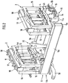
- a multi-strand caster ( Fig. 1 ) with a plurality of casting strands 3 running parallel in the casting direction 1 for the casting strands by a continuous casting mold (not shown) and support roll scaffolds in segmental shape (not shown) are for long products such as billets, bloom (pre-block), round or profile cross sections, the continuous casting molds einzein arranged side by side.
- Each of the continuous casting molds is stored separately in an oscillatingly drivable oscillating frame 2 in the casting direction 1.
- a swing frame 2 is by means of leaf springs 4 ( Fig. 2 ) is connected to the continuous casting mold or the mold table. The oscillatory movements take place in the casting direction 1 as a sinusoidal movement.
- the oscillation frequency and the oscillation height are coordinated.
- the leaf spring pairs 4a and 4b extend transversely to the casting direction 1, crossing the cast strand 3, and serve for guidance and for Gewiohtskompensation on a foundation frame fifth
- each foundation frame 5 is executed in strand direction 1 as an elongated rectangle.
- the foundation frame 5 is formed in each case from longitudinal bars 5a and 5b.
- each flat box 6 which extends transversely to the cast strand 3 in its longitudinal extent and bridges the gap between the two longitudinal bars 5a and 5b.
- Each flat box 6 consists of a closed housing 6a, wherein a rear flat boxes 6b and a front flat box 6c is formed with the required distance for installation of a continuous casting mold.
- the leaf springs to be described in more detail 4 are on the base frame 8, of which two are in each case parallel and spaced, the leaf springs to be described in more detail 4 as upper and lower leaf spring pairs 4a and 4b transverse to the strand direction 1, joints forming attached.
- a water tensioning plate 9 is provided for cooling the continuous casting mold with a cooling medium feed 10 formed from below.
- each Flachkestens 6 Is with open housings 6a, ie with removed protective cover 7 in Fig. 2 represents.
- Each flat box 6, ie always two pairs of upper leaf spring pairs 4a and lower leaf spring pairs 4b is associated with an oscillating drive 11 which is fastened via a connection bridge 12.
- the resulting front oscillating drive 11 a and the rear oscillating drive 11 b are synchronized and thereby cause unequal strokes but the same frequency a curve course.
- the oscillation drives 11 a and 11 b are designed for example as hydraulic oscillation drive units 14 and therefore via hydraulic lines 15 fed.
- a flat box 6 of two in strand direction 1 ( Fig. 1 ) arranged one behind the other, parallel rectangular frame 16 for each leaf spring pair 4a, 4b formed with height-spaced leaf springs 4 and between the rectangular frame 16 each a mold support frame 17 is arranged swingably.
- Each of the mold support frames 17 carries two mold support surfaces 18 disposed in the ends.
- the oscillation drive units 14 are located in the middle plane 19 (FIG. Fig. 1 ) of the casting strands 3 below the two rectangular frame 16 and between the longitudinal beams 5a, 5b of the foundation frame fifth
- Fig. 1 and 2 are in the foundation frame 5 between the longitudinal beams 5a, 5b suspension elements 20 for the suspension of a (not shown) Support roller segment stored, which encloses the casting strands 3 in the course behind the continuous casting mold.
- the suspension elements 20 consist of a rotatably mounted on the longitudinal beams 5a, 5b, two-armed levers 21 with a lever at a end 21a ( Fig. 3 ) formed hook-on depression 22 and connected to the other end of the lever 21b adjusting means 23 to determine the exact position of the suspended support roller segment.
- each of the compact flat boxes 6 contains two base frames 8 between each of which is the swing frame 2.
- the four mold support surfaces 18 visible.
- the adjusting means 23 for the two-armed lever 21 with the hulls 22 can be seen.
- remote protection covers 7 the view of a base frame 8, which receives an upper leaf spring pair 4a and a lower leaf spring pair 4b, and released on the connecting bridge 12.
- the view is directed perpendicular to the oscillation drive 11, the hydraulic lines 15 can be seen.
- the rectangular frame 16 is surmounted by a certain amount of the mold support frame 17 with the mold support surfaces 18.
- the cooling medium supply 10 and the cooling medium discharge 24 are arranged on the rear side of the device.
Landscapes
- Engineering & Computer Science (AREA)
- Mechanical Engineering (AREA)
- Continuous Casting (AREA)
Description
- Die Erfindung betrifft eine Vorrichtung zum Stranggießen von Metallen, insbesondere von Stahlwerkstoffen, zu Langprodukten in einer Mehrstrang-Gießanlage, mit mehreren Stranggießkokillen, die jeweils getrennt in einem in Gießrichtung oszillierend antreibbaren Schwingrahmen gelagert sind, der mittels beidseitig zum Gießstrang angeordneten Blattfeder-Paaren, die sich quer zur Gießrichtung erstrecken, zur Führung und Gewichtskompensation auf einem Fundamentrahmen gelagert ist.
- Aus der
EP 0 468 607 B2 Ist eine flüssigkeitsgekühlte Kokille zum Stranggießen von Metallen nach dem Oberbegriff von Anspruch 1 bekannt, mit der Knüppel-, Bloom- und Rundstränge mittels einer Rohrkokille gegossen werden. Dazu wird die Masse der Kokille für die einzelnen Strangformate in Betracht gezogen und festgestellt, dass für Brammenformate das Gewicht der Kokille bei ca. 30 t liege und das Gewicht einer Kokille für Rund- und Rechteckstränge bei 1,3 bis 2,5 t. Der Vorschlag beschäftigt sich dann mit der Reduzierung der Kokillen-Gewichte, um höhere Schwingungszahlen bei geringstmöglichem Kraftbedarf zu erreichen. - Aus der
US 4,195,684 sind eine Vorrichtung und ein Verfahren bekannt, wobei eine Mehrzahl von Kokillen durch einen Oszillationsmechanismus in Oszillation versetzt wird, wobei der Oszillatlonsmechanlsmus unabhängig vom Strangzwiachenraum angeordnet Ist, der lediglich von den Abmessungen einer Kupferplatte und eines Wasserkühlmantels für jede Kokille abhängt. Die Gussprodukte, die die Kokillen verlassen, werden mittels einer Mehrzahl von Treibrollen mit koaxial ineinandergreifenden Wellen abgezogen. Hierdurch kann der Zwischenraum zwischen den einzelnen Strängen vermindert werden, wodurch der Raumbedarf zur Instalüerung einer solchen Vorrichtung herabgesetzt werden kann. - Aus der
US 5,771,957 ist eine Einrichtung zum Stranggießen von Stahl bekannt, die aus einer in Gießrichtung oszillierenden Stranggießkokille besteht, die an quer zur Gießrichtung sich erstreckenden, beidendig eingespannten Federn gelagert und mit einem an einem Tragrahmen fest verbundenen, als Servo-Hydraulikzylinder ausgebildeten Oszillatlonsantrieb verbunden Ist. Die Servo-Hydraulikzylinder sind in einer durch die Stranggießkokille gelegten Längsschnittebene seitlich neben der Stranggießkokille angeordnet mit dem Tragrahmen spielfrei fest verbunden, wobei die Stranggießkokille an den Federn in einem Punkt befestigt ist und die freien Enden der Federn mit dem Tragrahmen In fester Verbindung stehen. Bei der Einrichtung gemaßUS 5,771,957 handelt es sich um eine sogenannte Resonanzkokille, bei der die Federstärke auf die Masse der Kokille derart abgestimmt ist, dass die Einrichtung im Resonanzbereich schwingt. - Demgegenüber bezieht sich die vorliegende Erfindung auf sog, Mehrstrang-Gießanlagen, bei der mehrere Gießstränge nebeneinander gleichzeitig erzeugt werden. Bei solchen Mehrstrang-Gießanlagen ist man bestrebt, einen möglichst kleinen Strangabstand von Gießstrang, zu Gießstrang, d.h. von Kokillenmitte zu Kokillenmitte zu erzielen. Bei neu zu bauenden Stranggießanlagen werden dadurch die Kosten reduziert und bei Umbauten bestehender Anlagen können nachträglich noch Änderungen durchgeführt werden. So kann bspw. nachträglich noch eine Rührspule, die den flüssigen Kern des Gießstranges beeinflusst, eingebaut werden.
- Der Erfindung liegt die Aufgabe zugrunde, auch bei sog. Resonanzkokillen, die eingangs bezeichnet sind und deren wesentliches Merkmal Blattfeder-Pakete sind, konstruktiv geringstmögliche Strangabstände zwischen den Gießsträngen zu erzielen. Die gestellte Aufgabe wird erfindungsgemäß dadurch gelöst, dass bei der eingangs bezeichneten Vorrichtung auf einem länglichen Fundamentrahmen In Stranglaufrichtung zwei hintereinander angeordnete, in Form von kompakten Flachkästen ausgebildete Gehäuse befestigt sind, in denen obere und untere Blattfeder-Paare quer zur Stranglaufrichtung verlaufen und dass an den Blattfeder-Paaren Oszillationsantriebe angreifen, wobei ein vorderer Oszillationsantrieb zum hinteren Oszillationsantrieb synchronisiert arbeitet. Der Vorteil ist bei einer solchen Quer-Anordnung durch Kreuzen des Gießstrangs bzw. der Stranglaufrichtung gegenüber der bisherigen Längs-Anordnung eine erhebliche Platz- und Raumersparnis, so dass der Abstand von Gießstrang zu Gießstrang, so klein wie möglich gehalten werden kann. Die Hintereinander-Anordnung der Flachkästen mit den Oszillationsantrieben in Gießrichtung bei einem kreuzenden Querverlauf der Blattfedern, quer zur Stranglaufrichtung bzw. Strangader, ermöglicht dabei, einen ausreichend großen Raum für die einzubauende Stranggießkokille zwischen den beiden Flachkästen zu schaffen. Gleichzeitig wird auch genügend Freiraum für den Einbau des sog. Null-Stützrollen-Segmentes gewonnen. Nahezu der gesamte Strangabstand "A" kann ausgenutzt werden.
- Nach weiteren Merkmalen wird vorgeschlagen, dass der vordere Oszillationsantrieb zu dem hinteren Oszillationsantrieb für einen Bogenverlauf des Gießstrangs mit unterschiedlichen Hüben eingestellt ist. Der hintere Oszilletionsantrieb ist dabei auf einen höheren Hub gegenüber dem vorderen Oszillationsantrieb einzustellen.
- Ein anderer Vorteil besteht darin, dass die Oszillationsantriebe aus hydraulischen Antriebseinheiten bestehen. Die Oszillationsantriebe können In geschützten Räumen unterhalb des Fundamentrahmens angeordnet werden.
- Weitere Merkmale sind, dass der Flachkästen aus zwei in Stranglaufrichtung hintereinanderliegenden Rechteckrahmen für jeweils zwei Blattfeder-Paare mit der Höhe beabstandeten Blattfedern besteht und dass zwischen den Rechteckrahmen ein Kokillenauflage-Rahmen schwingbar angeordnet ist. Dadurch bilden die beiden Rechteckrahmen für den Kokillenauflage-Rahmen gleichzeitig eine Führung.
- Der besondere Schutz für die Antriebe wird dadurch erzielt, dass die Oszillations-Antriebseinheiten jeweils in der Mitten-Ebene des Gießstrangs unterhalb den beiden Rechteckrahmen und zwischen Längsholmen des Fundamentrahmens angeordnet sind. Neben der geschützten Lage sind dadurch die Befestigungsstellen vorteilhaft,
- Andere Merkmale ergeben sich dadurch, dass im Fundamentrahmen zwischen den Längsholmen Einhänge-Elemente für die Aufhängung eines Stützrollen-Segmentes gelagert sind. Dadurch wird der Einbau vor der Montage der Stranggießkokille begünstigt.
- In einer Weiterbildung ist vorgesehen, dass die Einhänge-Elemente aus an einem auf den Längsholmen drehgelagerten, zweiarmigen Hebeln mit an einem Hebelende ausgebildeter Einhänge-Mulde und am anderen Hebelende angeschlossenen Justiermittein bestehen.
- Die Gestaltung der Vorrichtung ist ferner dadurch weiterentwickelt, dass eine Wasserspannplatte zur Versorgung der Stranggießkokille mit Kühlmedium auf dem hinteren Flachkasten angeordnet ist und dass die Kühlmedium-Zuführung und die Kühlmedium-Abführung nach hinten vom Gießstrang weg verlaufen.
- In der Zeichnung sind Ausführungsbeispiele der Erfindung dargestellt, die nachfolgend näher erläutert werden.
- Es zelgen:
- Fig. 1
- eine perspektivische Darstellung der Vorrichtung in Gesamtansicht,
- Fig. 2
- die perspektivische Darstellung gemäß
Fig. 1 ohne Schutzabdeckungen, - Fig. 3
- eine Seitenansicht in der Ebene, ohne den ersten Gießstrang,
- Fig. 4
- eine Draufsicht auf die Vorrichtung,
- Fig. 5
- eine Vorderansicht gegen die Vorrichtung bei abgenommener Schutzabdeckung, und
- Fig. 6
- eine Ansicht von unten gegen die Vorrichtung.
- In einer Mehrstrang-Gießanlage (
Fig. 1 ) mit mehreren In Gießrichtung 1 parallel verlaufenden Gießsträngen 3 für die Gießstränge durch jeweils eine Stranggießkokille (nicht gezeichnet) und Stützrollengerüste in Segmentform (nicht gezeichnet) gebildet sind, sind für Langprodukte, wie z.B. Knüppel, Bloom (Vor-block-), Rund- oder ProfilQuerschnitte, die Stranggießkokillen einzein nebeneinander angeordnet. Jede der Stranggießkokillen ist getrennt in einem in Gießrichtung 1 oszillierend antreibbaren Schwingrahmen 2 gelagert. Ein Schwingrahmen 2 ist mittels Blattfedern 4 (Fig. 2 ) mit der Stranggießkokille oder dem Kokillentisch verbunden. Die Schwingbewegungen erfolgen in Gießrichtung 1 als sinusförmige Bewegung. In den meisten Fällen wird dabei eine größere Geschwindigkeit während der Abwärtsbewegung der Stranggießkokille als die Geschwindigkeit des Gießstrangs 3 ist, eingehalten. Die Oszillationsfrequenz und die Schwingungshöhe sind aufeinander abgestimmt. Die Blattfeder-Paare 4a und 4b erstrecken sich quer zur Gießrichtung 1, den Gießstrang 3 kreuzend, und dienen zur Führung und zur Gewiohtskompensation auf einem Fundamentrahmen 5. - Um mehrere der Gießstränge 3 nebeneinander so eng wie möglich unterbringen zu können, d.h. um klein zu haltende Abstände "A" zu erreichen (
Fig. 1 ), ist jeder Fundamentrahmen 5 in Stranglaufrichtung 1 als längliches Rechteck ausgeführt. Der Fundamentrahmen 5 Ist Jeweils aus Längsholmen 5a und 5b gebildet. - Am hinteren Ende und am vorderen Ende des Fundamentrahmens 5 befindet sich jeweils ein kompakter Flachkasten 6, der in seiner Längserstreckung quer zum Gießstrang 3 verläuft und den Zwischenraum der beiden Längsholme 5a und 5b überbrückt. Jeder Flachkasten 6 besteht aus einem geschlossenen Gehäuse 6a, wobei ein hinterer Flachkästen 6b und ein vorderer Flachkasten 6c mit dem erforderlichen Abstand zum Einbau einer Stranggießkokille gebildet ist.
- Jeder Flachkasten 6 bildet das Gehäuse 6a zusammen mit beidseitigen Schutzabdeckungen 7. Im Innern des Gehäuses 6a sind am Grundrahmen 8, von denen jeweils zwei parallel und beabstandet sind, die noch näher zu beschreibenden Blattfedern 4. als obere und untere Blattfeder-Paare 4a und 4b quer zur Stranglaufrichtung 1, Gelenke bildend, befestigt. Zwischen den Grundrahmen 8 ist eine Wasserspannplatte 9 zur Kühlung der Stranggießkokille mit von unten gestalteter Kühlmedium-Zuführung 10 vorgesehen.
- Die Ausbildung jedes Flachkestens 6 Ist bei geöffneten Gehäusen 6a, d.h. bei entfernter Schutzabdeckung 7 in
Fig. 2 darstellt. Jedem Flachkasten 6, d.h. immer zwei Paaren von oberen Blattfederpaaren 4a und unteren Blattfederpaaren 4b Ist ein Oszillationsantrieb 11 zugeordnet, der über eine Verbindungsbrücke 12 befestigt Ist. Der sich daraus ergebende vordere Oszillationsantrieb 11 a und der hintere Oszillationsantrieb 11 b sind synchronisiert und bewirken dadurch bei ungleichen Hüben aber gleicher Frequenz einen Bogenverlauf 13. Die Oszillations-Antriebe 11a und 11 b sind z.B. als hydraulische Oszillations-Antriebseinheiten 14 ausgeführt und daher über Hydraulikleitungen 15 gespeist. - Wie weiterhin aus
Fig. 2 ersichtlich ist, wird ein Flachkasten 6 aus zwei in Stranglaufrichtung 1 (Fig. 1 ) hintereinander liegende, parallel verlaufende Rechteck-Rahmen 16 für jeweils ein Blattfeder-Paar 4a, 4b mit in der Höhe beabstandete Blattfedern 4 gebildet und zwischen den Rechteck-Rahmen 16 ist jeweils ein Kokillen-Auflagerahmen 17 schwingbar angeordnet. Jeder der Kokillen-Auflagerahmen 17 trägt zwei in den Enden angeordnete Kokillen-Stützflächen 18. - Die Oszillations-Antriebseinheiten 14 befinden sich in der Mitten-Ebene 19 (
Fig. 1 ) der Gießstränge 3 unterhalb den beiden Rechteck-Rahmen 16 und zwischen den Längsholmen 5a, 5b des Fundamentrahmens 5. - Gemäß den
Fig. 1 und2 sind Im Fundamentrahmen 5 zwischen den Längsholmen 5a, 5b Einhänge-Elemente 20 für die Aufhängung eines (weiter nicht gezeigten) Stützrollen-Segmentes gelagert, das die Gießstränge 3 Im Verlauf hinter der Stranggießkokille umschließt. Die Einhänge-Elemente 20 bestehen aus einem auf den Längsholmen 5a, 5b drehgelagerten, zweiarmigen Hebeln 21 mit einer an einem Hebelende 21a (Fig. 3 ) ausgebildeten Einhänge-Mulde 22 und an dem anderen Hebelende 21b angeschlossenen Justiermitteln 23, um die genaue Lage des eingehängten Stützrollen-Segmentes festzulegen. - Gemäß
Fig. 3 In Verbindung mitFig. 4 , weist der hintere Flachlsasten 6b die Wasserspannplatte 9 zur Versorgung der Stranggießkokille mit Kühlmedium auf. Außerdem ist ersichtlich, dass von dieser hinteren Seite der Vorrichtung die Kühlmedium-Zuführung 10 und eine Kühlmedium-Abführung 24 nach hinten vom heißen Gießstrang 3 abgewandt verläuft. - In der Draufsicht der
Fig. 4 sind die beidseitig angeordnete Kühlmedium-Zuführung 10 und die Kühlmedium-Abführung 24 sichtbar, ferner die Hydraulikleitungen 15 für den Oszillationsantrieb 11. Jeder der kompakten Flachkästen 6 enthält zwei Grundrahmen 8. Zwischen diesen liegt jeweils der Schwingrahmen 2. Außerdem sind die vier Kokillen-Stützflächen 18 sichtbar. Ebenso sind die Justiermittel 23 für die zweiarmigen Hebel 21 mit den Einhängemulden 22 zu sehen. - In der Vorderansicht der
Fig. 5 ist bei entfernten Schutzabdeckungen 7 der Blick auf einen Grundrahmen 8, der ein oberes Blattfeder-Paar 4a und ein unteres Blattfeder-Paar 4b aufnimmt, und auf die Verbindungsbrücke 12 freigegeben. Außerdem ist der Blick senkrecht auf den Oszillationsantrieb 11 gerichtet, dessen Hydraulikleitungen 15 zu sehen sind. Der Rechteckrahmen 16 wird um ein bestimmtes Maß von dem Kokillen-Auflagerahmen 17 mit den Kokillen-Stützflächen 18 überragt. Die Kühlmedium-Zuführung 10 und die Kühlmedium-Abführung 24 sind auf der hinteren Seite der Vorrichtung angeordnet. - In der Ansicht von unten,
Fig. 6 , sind die hydraulischen Oszillations-Antriebseinheiten 14 von unten her sichtbar, Außerdem fällt der Blick auf die Hydraulikleitungen 15, die sich auf beiden Seiten des Fundamentrahmens 5 mit den Längsholmen 5a und 5b befinden. Ebenso sind die Justiermittel 23 (mit den hier nicht sichtbaren Einhängemulden 22) für ein Stützrollen-Segment von unten sichtbar. -
- 1 Gießrichtung , Stranglaufrichtung
- 2 Schwingrahmen
- 3 Gießstrang
- 4 Blattfedern
- 4a oberes Blattfeder-Paar
- 4b unteres Blattfeder-Paar
- 5 Fundamentrahmen
- 5a Längsholm
- 5b Längsholm
-
- 6 kompakter Flachkasten
- 6a Gehäuse
- 6b hinterer Flachkasten
- 6c vorderer Flachkasten
- 7 Schutzabdeckung
- 8 Grundrahmen
- 9 Wasserspannplatte
- 10 Kühlmedium-Zuführung
- 11 Oszillationsantrieb
- 11 a vorderer Oszillatlonsantrieb
- 11b hinterer Oszillationsantrieb
- 12 Verbindungsbrücke
- 13 Bogenverlauf des Gießstrangs
- 14 hydraulische Oszillations-Antriebseinheit
- 15 Hydraulikleitungen
- 16 Rechteckrahmen
- 17 Kokillen-Auflagerahmen
- 18 Kokillen-Stützfläche
- 19 Mitten-Ebene des Gießstrangs
- 20 Einhänge-Element
- 21 zweiarmiger Hebel
- 21 a Hebelende
- 21b Hebelende
- 22 Einhänge-Mulde
- 23 Justiermittel
- 24 Kühlmedium-Abführung
Claims (8)
- Vorrichtung zum Stranggießen von Metallen, insbesondere von Stahlwerkstoffen, zu Langprodukten in einer Mehrstrang-Gießanlage, mit mehreren Stranggießkokillen, die jeweils getrennt in einem in Gießrichtung (1) oszillierend antreibbaren Schwingrahmen (2) gelagert sind, der mittels beidseitig zum Gießstrang (3) angeordneten oberen und unteren etwa horizontalen Blattfeder-Paaren (4) zur Führung und
Gewichtskompensation auf einem Fundamentrahmen gelagert ist, dadurch gekennzeichnet,
dass auf einem länglichen Fundamentrahmen (5) in Stranglaufrichtung (1) zwei hintereinander angeordnete, In Form von kompakten Flachkästen (6) ausgebildete Gehäuse (6a) befestigt sind, in denen die oberen und unteren Blattfeder-Paare (4a; 4b) quer zur Stranglaufrichtung (1) verlaufen und dass an den Blattfeder-Paaren (4a; 4b) Oszillationsantriebe (11) angreifen, wobei ein vorderer Oszillationsantrieb (11 a) zum hinteren Oszillationsantrieb (11b) synchronisiert arbeitet. - Vorrichtung nach Anspruch 1,
dadurch gekennzeichnet,
dass der vordere Oszillationsantrieb (11a) zu dem hinteren Oszillatlonsantrieb (11b) für einen Bogenverlauf (13) des Gießstrangs (3) mit unterschiedlichen Hüben eingestellt ist - Vorrichtung nach einem der Ansprüche 1 oder 2,
dadurch gekennzeichnet,
die Oszillationsantriebe (11a; 11b) aus hydraulischen Antriebseinheiten (14) bestehen. - Vorrichtung nach einem der Ansprüche 1 bis 3,
dadurch gekennzeichnet,
dass der Flachkasten (6) aus zwei in Stranglaufrichtung (1) hintereinanderliegenden Rechteckrahmen (16) für jeweils zwei Blattfeder-Paare (4a;4b) mit in der Höhe beabstandeten Blattfedern (4) besteht und dass zwischen den Rechteckrahmen (16) ein Kokillenauflage-Rahmen (17) schwingbar angeordnet ist. - Vorrichtung nach einem der Ansprüche 1 bis 4,
dadurch gekennzeichnet,
dass die Oszillations-Antriebseinheiten (14) jeweils in der Mitten-Ebene (19) des Gießstranges (3) unterhalb den beiden Rechteckrahmen (16) und zwischen Längsholmen (5a; 5b) des Fundamentrahmens (5) angeordnet sind. - Vorrichtung nach einem der Ansprüche 1 bis 5
dadurch gekennzeichnet,
dass Im Fundamentrahmen (5) zwischen den Längsholmen (5a; 5b) Einhänge-Elemente (20) für die Aufhängung eines Stützrollen-Segmentes gelagert sind. - Vorrichtung nach Anspruch 6,
dadurch gekennzeichnet,
dass die Einhänge-Elemente (20) aus an einem auf den Längsholmen (5a; 5b) drehgelagerten, zweiarmigen Hebeln (21) mit an einem Hebelende (21a) ausgebildeter Einhänge-Mulde (22) und am anderen Hebelende (21b) angeschlossenen Justiermitteln (23) bestehen. - Vorrichtung nach einem der Ansprüche 1 bis 7,
dadurch gekennzeichnet,
dass eine Wasserspannplatte (9) zur Versorgung der Stranggießkokille mit Kühlmedium auf dem hinteren Flachkasten (6b) angeordnet ist und dass die Kühlmedium-Zuführung (10) und die Kühlmedium-Abführung (24) nach hinten vom Gießstrang (3) weg verlaufen.
Applications Claiming Priority (3)
| Application Number | Priority Date | Filing Date | Title |
|---|---|---|---|
| DE10244596A DE10244596B4 (de) | 2002-09-21 | 2002-09-21 | Vorrichtung zum Stranggießen von Metallen, insbesondere von Stahlwerkstoffen, zu Langprodukten in einer Mehrstrang-Gießanlage |
| DE10244596 | 2002-09-21 | ||
| PCT/EP2003/009710 WO2004028723A1 (de) | 2002-09-21 | 2003-09-02 | Vorrichtung zum stranggiessen von metallen, insbesondere von stahlwerkstoffen, zu langprodukten in einer mehrstrang-giessanlage |
Publications (2)
| Publication Number | Publication Date |
|---|---|
| EP1539403A1 EP1539403A1 (de) | 2005-06-15 |
| EP1539403B1 true EP1539403B1 (de) | 2017-01-04 |
Family
ID=31969553
Family Applications (1)
| Application Number | Title | Priority Date | Filing Date |
|---|---|---|---|
| EP03798146.1A Revoked EP1539403B1 (de) | 2002-09-21 | 2003-09-02 | Vorrichtung zum stranggiessen von metallen, insbesondere von stahlwerkstoffen, zu langprodukten in einer mehrstrang-giessanlage |
Country Status (10)
| Country | Link |
|---|---|
| US (1) | US7036557B2 (de) |
| EP (1) | EP1539403B1 (de) |
| JP (1) | JP4272158B2 (de) |
| KR (1) | KR101031610B1 (de) |
| CN (1) | CN100584486C (de) |
| AU (1) | AU2003266344A1 (de) |
| CA (1) | CA2499270C (de) |
| DE (1) | DE10244596B4 (de) |
| TW (1) | TWI279267B (de) |
| WO (1) | WO2004028723A1 (de) |
Families Citing this family (8)
| Publication number | Priority date | Publication date | Assignee | Title |
|---|---|---|---|---|
| DE102004018602A1 (de) * | 2004-04-16 | 2005-11-03 | Sms Demag Ag | Oszillationsvorrichtung für Stranggießkokillen zum Gießen von flüssigem Metall, insbesondere von flüssigem Stahlwerkstoff |
| DE102005019295A1 (de) * | 2004-07-06 | 2006-02-02 | Sms Demag Ag | Vorrichtung für die Stützung und Oszillation einer Stranggiesskokille von flüssigen Metallen, insbesondere von flüssigen Stahlwerkstoffen und Verfahren zum Montieren und Demontieren sowie Instandhalten |
| DE102005017226A1 (de) * | 2004-07-06 | 2006-02-02 | Sms Demag Ag | Vorrichtung für die Stützung und Oszillation einer Stranggießkokille zum Gießen von flüssigem Metall, insbesondere von flüssigem Stahlwerkstoff |
| DE102008015827A1 (de) * | 2008-03-27 | 2009-10-01 | Sms Siemag Aktiengesellschaft | Vorrichtung für die Stützung und Oszillation einer Stranggießkokille |
| AT508395B1 (de) * | 2009-06-16 | 2014-08-15 | Tbr Casting Technologies Gmbh | Mittel zum oszillieren einer stranggiesskokille |
| EP2905093B1 (de) * | 2014-02-07 | 2018-08-29 | SMS Concast AG | Kokillenanordnung zum Stranggiessen von metallischen Produkten |
| CN114309502A (zh) * | 2021-12-24 | 2022-04-12 | 衡阳镭目科技有限责任公司 | 一种单元式单驱动结晶器振动装置 |
| CN115178716B (zh) * | 2022-06-13 | 2026-02-03 | 湖北中钢联冶金工程有限公司 | 一种结晶器用振动机构 |
Citations (12)
| Publication number | Priority date | Publication date | Assignee | Title |
|---|---|---|---|---|
| US4195684A (en) | 1975-12-18 | 1980-04-01 | Ishikawajima-Harima Jukogyo Kabushiki Kaisha | Apparatus for multi-strand continuous casting |
| DE3706720A1 (de) | 1987-03-02 | 1988-09-15 | Voest Alpine Ag | Stranggiessanlage mit zwei nebeneinander angeordneten druchlaufkokillen |
| EP0468607B1 (de) | 1990-07-23 | 1995-04-19 | MANNESMANN Aktiengesellschaft | Flüssigkeitsgekühlte Kokille für das Stranggiessen von Metallen |
| WO1995015232A1 (de) | 1993-12-03 | 1995-06-08 | Mannesmann Ag | Einrichtung zum stranggiessen von stahl |
| DE4444941A1 (de) | 1993-12-20 | 1995-06-22 | Voest Alpine Ind Anlagen | Stranggießkokille |
| US5623983A (en) | 1994-12-21 | 1997-04-29 | Voest-Alpine Industrieanlagenbau Gmbh | Continuous casting mold |
| US5642769A (en) | 1994-12-21 | 1997-07-01 | Voest-Alpine Industrieanlagenbau Gmbh | Continuous casting mold |
| WO1999012676A1 (de) | 1997-09-08 | 1999-03-18 | Voest-Alpine Industrieanlagenbau Gmbh | Stranggiesseinrichtung |
| EP0953391A1 (de) | 1998-04-21 | 1999-11-03 | Sms Schloemann-Siemag Aktiengesellschaft | Hubtisch mit Oszillationsantrieb für eine Stranggiesseinrichtung |
| US6167941B1 (en) | 1997-12-06 | 2001-01-02 | Sms Schloemann-Siemag Ag | Support structure for oscillating continuous casting mold |
| DE10024514A1 (de) | 1999-06-08 | 2001-01-04 | Voest Alpine Ind Anlagen | Stranggießanlage |
| WO2001085370A1 (de) | 2000-05-10 | 2001-11-15 | Sms Demag Aktiengesellschaft | Vorrichtung zum stranggiessen von metallen, insbesondere von stahl |
Family Cites Families (2)
| Publication number | Priority date | Publication date | Assignee | Title |
|---|---|---|---|---|
| CA1316325C (en) * | 1987-08-29 | 1993-04-20 | Masatsugu Uehara | Method of oscillating continuous casting mold at high frequencies and mold oscillated by such method |
| CN1223915A (zh) * | 1997-12-06 | 1999-07-28 | Sms舒路曼-斯玛公司 | 振动式结晶器的支架 |
-
2002
- 2002-09-21 DE DE10244596A patent/DE10244596B4/de not_active Expired - Fee Related
-
2003
- 2003-09-01 TW TW092124064A patent/TWI279267B/zh not_active IP Right Cessation
- 2003-09-02 AU AU2003266344A patent/AU2003266344A1/en not_active Abandoned
- 2003-09-02 CA CA2499270A patent/CA2499270C/en not_active Expired - Fee Related
- 2003-09-02 US US10/528,380 patent/US7036557B2/en not_active Expired - Lifetime
- 2003-09-02 CN CN03822459A patent/CN100584486C/zh not_active Expired - Fee Related
- 2003-09-02 JP JP2004538859A patent/JP4272158B2/ja not_active Expired - Fee Related
- 2003-09-02 EP EP03798146.1A patent/EP1539403B1/de not_active Revoked
- 2003-09-02 KR KR1020057004823A patent/KR101031610B1/ko not_active Expired - Fee Related
- 2003-09-02 WO PCT/EP2003/009710 patent/WO2004028723A1/de not_active Ceased
Patent Citations (14)
| Publication number | Priority date | Publication date | Assignee | Title |
|---|---|---|---|---|
| US4195684A (en) | 1975-12-18 | 1980-04-01 | Ishikawajima-Harima Jukogyo Kabushiki Kaisha | Apparatus for multi-strand continuous casting |
| DE3706720A1 (de) | 1987-03-02 | 1988-09-15 | Voest Alpine Ag | Stranggiessanlage mit zwei nebeneinander angeordneten druchlaufkokillen |
| EP0468607B1 (de) | 1990-07-23 | 1995-04-19 | MANNESMANN Aktiengesellschaft | Flüssigkeitsgekühlte Kokille für das Stranggiessen von Metallen |
| WO1995015232A1 (de) | 1993-12-03 | 1995-06-08 | Mannesmann Ag | Einrichtung zum stranggiessen von stahl |
| US5771957A (en) | 1993-12-03 | 1998-06-30 | Mannesmann Aktiengesellschaft | Device for the continuous casting of steel |
| DE4444941A1 (de) | 1993-12-20 | 1995-06-22 | Voest Alpine Ind Anlagen | Stranggießkokille |
| US5642769A (en) | 1994-12-21 | 1997-07-01 | Voest-Alpine Industrieanlagenbau Gmbh | Continuous casting mold |
| US5623983A (en) | 1994-12-21 | 1997-04-29 | Voest-Alpine Industrieanlagenbau Gmbh | Continuous casting mold |
| WO1999012676A1 (de) | 1997-09-08 | 1999-03-18 | Voest-Alpine Industrieanlagenbau Gmbh | Stranggiesseinrichtung |
| US6167941B1 (en) | 1997-12-06 | 2001-01-02 | Sms Schloemann-Siemag Ag | Support structure for oscillating continuous casting mold |
| EP0953391A1 (de) | 1998-04-21 | 1999-11-03 | Sms Schloemann-Siemag Aktiengesellschaft | Hubtisch mit Oszillationsantrieb für eine Stranggiesseinrichtung |
| DE10024514A1 (de) | 1999-06-08 | 2001-01-04 | Voest Alpine Ind Anlagen | Stranggießanlage |
| AT408625B (de) | 1999-06-08 | 2002-01-25 | Voest Alpine Ind Anlagen | Stranggiessanlage |
| WO2001085370A1 (de) | 2000-05-10 | 2001-11-15 | Sms Demag Aktiengesellschaft | Vorrichtung zum stranggiessen von metallen, insbesondere von stahl |
Non-Patent Citations (7)
| Title |
|---|
| "VOEST-ALPINE Industrieanlagenbau GmbH, Continuous Casting Division", May 1999, article "Product Info Billet/Bloom Caster, DYNAFLEX-Oscillator for Billet & Bloom Casters", XP055424638 |
| F. LEINGRUBER ET AL.: "High-Performance Machine Head - A Success Story", BILLET/BLOOM CASTING SESSION, no. 34, June 2000 (2000-06-01), pages 1 - 4, XP055424558 |
| H. HÖDL ET AL.: "VAINOX - Latest Developments in Stainless Steel Casting Technologies", SLAB CASTING SESSION - PAPER NO. 15, CONTINUOUS CASTING CONFERENCE (CCC) 2000, no. 15, June 2000 (2000-06-01), Linz/ Austria (E2e), pages 1 - 17, XP55424668 |
| O. L. MANHÄES WAGNER ET AL.: "Casting Solutions for High Productivity and High Quality at CSN", SLAB CASTING SESSION - PAPER NO. 19, CONTINUOUS CASTING CONFERENCE (CCC) 2000, no. 19, June 2000 (2000-06-01), Linz/ Austria (E2c), pages 1 - 6, XP055424627 |
| T. HARALDSON ET AL.: "Modernisation of Slab Casters at SSAB Tunnplät", ASSOCIATION OF IRON AND STEEL ENGINEERS, 1998, Sweden (E2b3), XP055424623 |
| T. HARALDSON ET AL.: "Modernisation of the slab casters at SSAB Tunnplät", STEEL TIMES, January 2001 (2001-01-01), pages 26 - 27, XP055424572 |
| T. HARALDSON ET AL.: "SSAB Tunnplät - Luleä - DYNAFLEX Oscillator and Hydraulic Width-Adjustable Mold", SLAB CASTING SESSION - PAPER NO. 18, CONTINUOUS CASTING CONFERENCE (CCC) 2000, no. 18, June 2000 (2000-06-01), Linz/ Austria (E2b1), pages 1 - 6, XP055424564 |
Also Published As
| Publication number | Publication date |
|---|---|
| TW200404627A (en) | 2004-04-01 |
| AU2003266344A1 (en) | 2004-04-19 |
| US7036557B2 (en) | 2006-05-02 |
| EP1539403A1 (de) | 2005-06-15 |
| JP2005538852A (ja) | 2005-12-22 |
| KR20050057510A (ko) | 2005-06-16 |
| JP4272158B2 (ja) | 2009-06-03 |
| WO2004028723A1 (de) | 2004-04-08 |
| CA2499270A1 (en) | 2004-04-08 |
| DE10244596A1 (de) | 2004-04-01 |
| CN100584486C (zh) | 2010-01-27 |
| CA2499270C (en) | 2010-11-16 |
| TWI279267B (en) | 2007-04-21 |
| CN1681612A (zh) | 2005-10-12 |
| KR101031610B1 (ko) | 2011-04-28 |
| US20060048915A1 (en) | 2006-03-09 |
| DE10244596B4 (de) | 2011-12-29 |
Similar Documents
| Publication | Publication Date | Title |
|---|---|---|
| DE4341719C1 (de) | Einrichtung zum Stranggießen von Stahl | |
| EP0468607A1 (de) | Flüssigkeitsgekühlte Kokille für das Stranggiessen von Metallen | |
| EP1539403B1 (de) | Vorrichtung zum stranggiessen von metallen, insbesondere von stahlwerkstoffen, zu langprodukten in einer mehrstrang-giessanlage | |
| EP1763414B1 (de) | Vorrichtung für die stützung und oszillation einer stranggiesskokille zum stranggiessen von flüssigen metallen, insbesondere von flüssigen stahlwerkstoffen und verfahren zum montieren oder demontieren sowie instandhalten | |
| DE2021780C3 (de) | Verfahren zur Anpassung der Bogenfühning eines aus einer Stranggießkokille austretenden Stranges und Vorrichtung dazu | |
| EP1370379B1 (de) | Verfahren zum giessen und unmittelbar anschliessendem walzen und eine vorrichtung zur stützung, führung und verformung eines metall-, insbesondere eines stahlstranges | |
| DE4444941C3 (de) | Stranggießkokille | |
| DE1558220B2 (de) | Lagerung von Walzen fur die Form änderung eines aus einer Stranggießkokille kommenden metallischen Stranges | |
| EP1750871A1 (de) | Vorrichtung für die aufnahme einer stranggiesskokille auf einem hubtisch zum giessen von flüssigen metallen, insbesondere von flüssigen stahlwerkstoffen | |
| DE10024514C5 (de) | Stranggießanlage | |
| EP1029616B1 (de) | Vorrichtung zum Oszillieren einer Stranggiesskokille | |
| EP2275216B1 (de) | Mittel zum Oszillieren einer Stanggiesskolille | |
| EP1991379B1 (de) | Stranggiessanlage und verfahren zum betreiben einer stranggiessanlage | |
| DE60223996T2 (de) | Vorrichtung zur Herstellung von Rohblöcken aus einem Nichteisenmetall durch Stranggiessen. | |
| DE2733864A1 (de) | Vorrichtung zum kontinuierlichen giessen mehrerer straenge | |
| DE1758982A1 (de) | Laengsgeteilte Durchlaufgiessform fuer Metall,insbesondere Strahlstranggiessanlagen | |
| EP3354370B1 (de) | Oszillationssystem für eine stranggiesskokille, und verfahren zum erzeugen einer oszillationsbewegung einer stranggiesskokille | |
| DE2146963A1 (de) | Fuhrungsrollenanordnung fur Strang gußmaschine | |
| EP0041196A2 (de) | Verfahren und Vorrichtung zum Oszillieren einer Stranggiesskokille | |
| EP1057556B1 (de) | Stranggiesskokille zum Stranggiessen von vorzugsweise Dünnbrammen aus Stahl | |
| EP0946318A1 (de) | Verfahren und anlage zum stranggiessen von dünnbrammen | |
| DE2947869A1 (de) | Einrichtung und verfahren zum elektromagnetischen ruehren des sumpfes in einer stahlstranggiessanlage | |
| DE4447941B4 (de) | Stranggießkokille | |
| EP0068208B1 (de) | Stahlstranggiessanlage | |
| DE3407139A1 (de) | Fuehrungseinrichtung an den giessbaendern einer doppelbandstranggiesskokille |
Legal Events
| Date | Code | Title | Description |
|---|---|---|---|
| PUAI | Public reference made under article 153(3) epc to a published international application that has entered the european phase |
Free format text: ORIGINAL CODE: 0009012 |
|
| 17P | Request for examination filed |
Effective date: 20050205 |
|
| AK | Designated contracting states |
Kind code of ref document: A1 Designated state(s): AT BE BG CH CY CZ DE DK EE ES FI FR GB GR HU IE IT LI LU MC NL PT RO SE SI SK TR |
|
| AX | Request for extension of the european patent |
Extension state: AL LT LV MK |
|
| DAX | Request for extension of the european patent (deleted) | ||
| RAP1 | Party data changed (applicant data changed or rights of an application transferred) |
Owner name: SMS SIEMAG AG |
|
| 17Q | First examination report despatched |
Effective date: 20120625 |
|
| RAP1 | Party data changed (applicant data changed or rights of an application transferred) |
Owner name: SMS GROUP GMBH |
|
| GRAP | Despatch of communication of intention to grant a patent |
Free format text: ORIGINAL CODE: EPIDOSNIGR1 |
|
| INTG | Intention to grant announced |
Effective date: 20160729 |
|
| STAA | Information on the status of an ep patent application or granted ep patent |
Free format text: STATUS: GRANT OF PATENT IS INTENDED |
|
| GRAS | Grant fee paid |
Free format text: ORIGINAL CODE: EPIDOSNIGR3 |
|
| GRAA | (expected) grant |
Free format text: ORIGINAL CODE: 0009210 |
|
| STAA | Information on the status of an ep patent application or granted ep patent |
Free format text: STATUS: THE PATENT HAS BEEN GRANTED |
|
| AK | Designated contracting states |
Kind code of ref document: B1 Designated state(s): AT BE BG CH CY CZ DE DK EE ES FI FR GB GR HU IE IT LI LU MC NL PT RO SE SI SK TR |
|
| REG | Reference to a national code |
Ref country code: GB Ref legal event code: FG4D Free format text: NOT ENGLISH |
|
| REG | Reference to a national code |
Ref country code: CH Ref legal event code: EP |
|
| REG | Reference to a national code |
Ref country code: AT Ref legal event code: REF Ref document number: 858737 Country of ref document: AT Kind code of ref document: T Effective date: 20170115 |
|
| REG | Reference to a national code |
Ref country code: IE Ref legal event code: FG4D Free format text: LANGUAGE OF EP DOCUMENT: GERMAN |
|
| REG | Reference to a national code |
Ref country code: DE Ref legal event code: R096 Ref document number: 50315607 Country of ref document: DE |
|
| REG | Reference to a national code |
Ref country code: NL Ref legal event code: MP Effective date: 20170104 |
|
| PG25 | Lapsed in a contracting state [announced via postgrant information from national office to epo] |
Ref country code: NL Free format text: LAPSE BECAUSE OF FAILURE TO SUBMIT A TRANSLATION OF THE DESCRIPTION OR TO PAY THE FEE WITHIN THE PRESCRIBED TIME-LIMIT Effective date: 20170104 |
|
| PG25 | Lapsed in a contracting state [announced via postgrant information from national office to epo] |
Ref country code: GR Free format text: LAPSE BECAUSE OF FAILURE TO SUBMIT A TRANSLATION OF THE DESCRIPTION OR TO PAY THE FEE WITHIN THE PRESCRIBED TIME-LIMIT Effective date: 20170405 Ref country code: FI Free format text: LAPSE BECAUSE OF FAILURE TO SUBMIT A TRANSLATION OF THE DESCRIPTION OR TO PAY THE FEE WITHIN THE PRESCRIBED TIME-LIMIT Effective date: 20170104 |
|
| PG25 | Lapsed in a contracting state [announced via postgrant information from national office to epo] |
Ref country code: ES Free format text: LAPSE BECAUSE OF FAILURE TO SUBMIT A TRANSLATION OF THE DESCRIPTION OR TO PAY THE FEE WITHIN THE PRESCRIBED TIME-LIMIT Effective date: 20170104 Ref country code: SE Free format text: LAPSE BECAUSE OF FAILURE TO SUBMIT A TRANSLATION OF THE DESCRIPTION OR TO PAY THE FEE WITHIN THE PRESCRIBED TIME-LIMIT Effective date: 20170104 Ref country code: BG Free format text: LAPSE BECAUSE OF FAILURE TO SUBMIT A TRANSLATION OF THE DESCRIPTION OR TO PAY THE FEE WITHIN THE PRESCRIBED TIME-LIMIT Effective date: 20170404 Ref country code: PT Free format text: LAPSE BECAUSE OF FAILURE TO SUBMIT A TRANSLATION OF THE DESCRIPTION OR TO PAY THE FEE WITHIN THE PRESCRIBED TIME-LIMIT Effective date: 20170504 |
|
| REG | Reference to a national code |
Ref country code: DE Ref legal event code: R026 Ref document number: 50315607 Country of ref document: DE |
|
| PLBI | Opposition filed |
Free format text: ORIGINAL CODE: 0009260 |
|
| PG25 | Lapsed in a contracting state [announced via postgrant information from national office to epo] |
Ref country code: RO Free format text: LAPSE BECAUSE OF FAILURE TO SUBMIT A TRANSLATION OF THE DESCRIPTION OR TO PAY THE FEE WITHIN THE PRESCRIBED TIME-LIMIT Effective date: 20170104 Ref country code: EE Free format text: LAPSE BECAUSE OF FAILURE TO SUBMIT A TRANSLATION OF THE DESCRIPTION OR TO PAY THE FEE WITHIN THE PRESCRIBED TIME-LIMIT Effective date: 20170104 Ref country code: CZ Free format text: LAPSE BECAUSE OF FAILURE TO SUBMIT A TRANSLATION OF THE DESCRIPTION OR TO PAY THE FEE WITHIN THE PRESCRIBED TIME-LIMIT Effective date: 20170104 Ref country code: SK Free format text: LAPSE BECAUSE OF FAILURE TO SUBMIT A TRANSLATION OF THE DESCRIPTION OR TO PAY THE FEE WITHIN THE PRESCRIBED TIME-LIMIT Effective date: 20170104 |
|
| 26 | Opposition filed |
Opponent name: PRIMETALS TECHNOLOGIES AUSTRIA GMBH Effective date: 20171003 |
|
| PLAX | Notice of opposition and request to file observation + time limit sent |
Free format text: ORIGINAL CODE: EPIDOSNOBS2 |
|
| PG25 | Lapsed in a contracting state [announced via postgrant information from national office to epo] |
Ref country code: DK Free format text: LAPSE BECAUSE OF FAILURE TO SUBMIT A TRANSLATION OF THE DESCRIPTION OR TO PAY THE FEE WITHIN THE PRESCRIBED TIME-LIMIT Effective date: 20170104 |
|
| PG25 | Lapsed in a contracting state [announced via postgrant information from national office to epo] |
Ref country code: SI Free format text: LAPSE BECAUSE OF FAILURE TO SUBMIT A TRANSLATION OF THE DESCRIPTION OR TO PAY THE FEE WITHIN THE PRESCRIBED TIME-LIMIT Effective date: 20170104 |
|
| PLBB | Reply of patent proprietor to notice(s) of opposition received |
Free format text: ORIGINAL CODE: EPIDOSNOBS3 |
|
| REG | Reference to a national code |
Ref country code: CH Ref legal event code: PL |
|
| GBPC | Gb: european patent ceased through non-payment of renewal fee |
Effective date: 20170902 |
|
| PG25 | Lapsed in a contracting state [announced via postgrant information from national office to epo] |
Ref country code: MC Free format text: LAPSE BECAUSE OF FAILURE TO SUBMIT A TRANSLATION OF THE DESCRIPTION OR TO PAY THE FEE WITHIN THE PRESCRIBED TIME-LIMIT Effective date: 20170104 |
|
| REG | Reference to a national code |
Ref country code: IE Ref legal event code: MM4A |
|
| REG | Reference to a national code |
Ref country code: BE Ref legal event code: MM Effective date: 20170930 |
|
| PG25 | Lapsed in a contracting state [announced via postgrant information from national office to epo] |
Ref country code: LU Free format text: LAPSE BECAUSE OF NON-PAYMENT OF DUE FEES Effective date: 20170902 |
|
| REG | Reference to a national code |
Ref country code: FR Ref legal event code: ST Effective date: 20180531 |
|
| PG25 | Lapsed in a contracting state [announced via postgrant information from national office to epo] |
Ref country code: CH Free format text: LAPSE BECAUSE OF NON-PAYMENT OF DUE FEES Effective date: 20170930 Ref country code: GB Free format text: LAPSE BECAUSE OF NON-PAYMENT OF DUE FEES Effective date: 20170902 Ref country code: LI Free format text: LAPSE BECAUSE OF NON-PAYMENT OF DUE FEES Effective date: 20170930 Ref country code: IE Free format text: LAPSE BECAUSE OF NON-PAYMENT OF DUE FEES Effective date: 20170902 |
|
| PG25 | Lapsed in a contracting state [announced via postgrant information from national office to epo] |
Ref country code: FR Free format text: LAPSE BECAUSE OF NON-PAYMENT OF DUE FEES Effective date: 20171002 Ref country code: BE Free format text: LAPSE BECAUSE OF NON-PAYMENT OF DUE FEES Effective date: 20170930 |
|
| PGFP | Annual fee paid to national office [announced via postgrant information from national office to epo] |
Ref country code: DE Payment date: 20180920 Year of fee payment: 16 Ref country code: IT Payment date: 20180925 Year of fee payment: 16 |
|
| PGFP | Annual fee paid to national office [announced via postgrant information from national office to epo] |
Ref country code: AT Payment date: 20180920 Year of fee payment: 16 |
|
| REG | Reference to a national code |
Ref country code: DE Ref legal event code: R064 Ref document number: 50315607 Country of ref document: DE Ref country code: DE Ref legal event code: R103 Ref document number: 50315607 Country of ref document: DE |
|
| RDAF | Communication despatched that patent is revoked |
Free format text: ORIGINAL CODE: EPIDOSNREV1 |
|
| PG25 | Lapsed in a contracting state [announced via postgrant information from national office to epo] |
Ref country code: HU Free format text: LAPSE BECAUSE OF FAILURE TO SUBMIT A TRANSLATION OF THE DESCRIPTION OR TO PAY THE FEE WITHIN THE PRESCRIBED TIME-LIMIT; INVALID AB INITIO Effective date: 20030902 |
|
| RDAG | Patent revoked |
Free format text: ORIGINAL CODE: 0009271 |
|
| STAA | Information on the status of an ep patent application or granted ep patent |
Free format text: STATUS: PATENT REVOKED |
|
| 27W | Patent revoked |
Effective date: 20190320 |
|
| REG | Reference to a national code |
Ref country code: AT Ref legal event code: MA03 Ref document number: 858737 Country of ref document: AT Kind code of ref document: T Effective date: 20190320 |
|
| PG25 | Lapsed in a contracting state [announced via postgrant information from national office to epo] |
Ref country code: CY Free format text: LAPSE BECAUSE OF FAILURE TO SUBMIT A TRANSLATION OF THE DESCRIPTION OR TO PAY THE FEE WITHIN THE PRESCRIBED TIME-LIMIT Effective date: 20170104 |
|
| PG25 | Lapsed in a contracting state [announced via postgrant information from national office to epo] |
Ref country code: TR Free format text: LAPSE BECAUSE OF FAILURE TO SUBMIT A TRANSLATION OF THE DESCRIPTION OR TO PAY THE FEE WITHIN THE PRESCRIBED TIME-LIMIT Effective date: 20170104 |