EP1538848A1 - Bildverarbeitungseinrichtung - Google Patents
Bildverarbeitungseinrichtung Download PDFInfo
- Publication number
- EP1538848A1 EP1538848A1 EP03748522A EP03748522A EP1538848A1 EP 1538848 A1 EP1538848 A1 EP 1538848A1 EP 03748522 A EP03748522 A EP 03748522A EP 03748522 A EP03748522 A EP 03748522A EP 1538848 A1 EP1538848 A1 EP 1538848A1
- Authority
- EP
- European Patent Office
- Prior art keywords
- correction
- color
- accordance
- image
- intensity
- Prior art date
- Legal status (The legal status is an assumption and is not a legal conclusion. Google has not performed a legal analysis and makes no representation as to the accuracy of the status listed.)
- Withdrawn
Links
Images








Classifications
-
- H—ELECTRICITY
- H04—ELECTRIC COMMUNICATION TECHNIQUE
- H04N—PICTORIAL COMMUNICATION, e.g. TELEVISION
- H04N1/00—Scanning, transmission or reproduction of documents or the like, e.g. facsimile transmission; Details thereof
- H04N1/46—Colour picture communication systems
- H04N1/56—Processing of colour picture signals
- H04N1/60—Colour correction or control
- H04N1/62—Retouching, i.e. modification of isolated colours only or in isolated picture areas only
-
- H—ELECTRICITY
- H04—ELECTRIC COMMUNICATION TECHNIQUE
- H04N—PICTORIAL COMMUNICATION, e.g. TELEVISION
- H04N1/00—Scanning, transmission or reproduction of documents or the like, e.g. facsimile transmission; Details thereof
- H04N1/46—Colour picture communication systems
- H04N1/56—Processing of colour picture signals
- H04N1/60—Colour correction or control
- H04N1/62—Retouching, i.e. modification of isolated colours only or in isolated picture areas only
- H04N1/628—Memory colours, e.g. skin or sky
-
- H—ELECTRICITY
- H04—ELECTRIC COMMUNICATION TECHNIQUE
- H04N—PICTORIAL COMMUNICATION, e.g. TELEVISION
- H04N23/00—Cameras or camera modules comprising electronic image sensors; Control thereof
- H04N23/80—Camera processing pipelines; Components thereof
- H04N23/84—Camera processing pipelines; Components thereof for processing colour signals
- H04N23/86—Camera processing pipelines; Components thereof for processing colour signals for controlling the colour saturation of colour signals, e.g. automatic chroma control circuits
-
- H—ELECTRICITY
- H04—ELECTRIC COMMUNICATION TECHNIQUE
- H04N—PICTORIAL COMMUNICATION, e.g. TELEVISION
- H04N9/00—Details of colour television systems
- H04N9/64—Circuits for processing colour signals
- H04N9/643—Hue control means, e.g. flesh tone control
Definitions
- the present invention relates to an image processing apparatus, an image processing method, a program, a recording medium, a printer apparatus, a television receiver, a projector apparatus, a photographing apparatus and a mobile communication terminal. More particularly, the present invention relates to a memory color correction technology of automatically converting the color in a specific region of an input image signal into a more desirable color, and is widely applicable to output devices, such as a display and a printer, input devices, such as a digital camera and a digital camcorder, and PC application software being used for photographic image databases and retouching.
- the color correction technologies required for numerous full-color devices such as a camera, a display and a printer, more specifically, the color correction technologies of correcting the inherent characteristics of devices, such as the spectroscopic characteristic of a CCD in a camera and the spectroscopic characteristic of ink in a printer, were being developed, the correction accuracy of the above-mentioned color correction was insufficient; on the assumption of this, the technologies conventionally referred to as selective color adjustment and memory color correction were intended to correct improper color reproduction owing to the insufficient accuracy.
- Japanese Laid-open Patent Application No. Sho 62-281062 the color in the skin color region having the largest number of pixels is corrected to a desirable skin color, wherein the number of pixels in the skin color region of an image is counted and the execution of correction is switched depending on whether the number of pixels in the skin color region exceeds a predetermined value or not.
- the correction target region is narrowed with respect to hue and saturation, whereby correction not extended to regions other than the correction region is attained.
- correction/no-correction is switched using the number of pixels in a skin color region; however, when the number of pixels in the skin color region is few, correction is not carried out, and when the number of pixels is large, correction is carried out for the color in the skin color region by the same amount. More specifically, the color judged to be inside the skin color region is subjected to the same amount of correction in the same direction regardless of whether the color is deviated in either direction from the reference color being set empirically. Hence, there is a color that is corrected in a direction opposite to the desirable direction. Such a color becomes discontinuous at the boundary of the region and causes color jumping.
- a correction region and the weight of correction are calculated according to the product of hue and saturation weighting functions, and hue, saturation and luminance are corrected by the amount proportional to the weight.
- Color continuity can be maintained by gently setting the weighting function in a wide range; however, the correction direction inside the correction region is still the same direction, and there is a color that is corrected in a direction opposed to the desirable correction direction.
- a correction region and the weight of correction are calculated using the minimum value of two weighting functions being orthogonal in a chromaticity plane, and the hue, saturation and luminance are shifted by the amount proportional to the weight, whereby it can be expected to have an effect of memory color correction; however, because the correction is carried out in a rectangular region in the chromaticity plane, it is difficult to narrow the regions of skin color and sky blue necessarily and sufficiently; if the effect is exerted, a side effect of correcting colors that should not be changed essentially is caused. In addition, if the size of the rectangular region is made smaller, the influence to colors other than the target color can be avoided, but changes in hue and saturation occurs in the target color, whereby the effect of memory color correction is lost.
- the above-mentioned inventions are not intended to carry out memory color correction not having side effects almost completely, but they are intended to shift such nearly similar colors in this way. Since the color correction technologies of correcting the inherent characteristics of devices were being developed as described above, the correction accuracy of the above-mentioned color correction was insufficient; on the assumption of this, the color regions unable to be corrected properly because of such reasons were corrected as a whole; it seems that there were no higher requests in those days.
- the present invention is intended to provide an image processing apparatus, an image processing method, a program, a recording medium, a printer, a television receiver, a projector apparatus, a photographing apparatus and a mobile communication terminal not causing a side effect of correcting colors that should not be subjected to memory color correction essentially.
- the present invention is intended to provide an image processing apparatus, an image processing method, a program, a recording medium, a printer, a television receiver, a projector apparatus, a photographing apparatus and a mobile communication terminal capable of avoiding correcting other objects included in the memory color region that should be corrected essentially but accidentally having colors close to the color to be corrected.
- the present invention is intended to provide an image processing apparatus, an image processing method, a program, a recording medium, a printer, a television receiver, a projector, a photographing apparatus and a mobile communication terminal not making gradation discontinuous and not causing color jumping.
- a first invention of the present invention is an image processing apparatus of correcting the color of a predetermined range of a pixel signal for each pixel included in an input image signal, comprising:
- a second invention of the present invention is an image processing apparatus of correcting the color of a predetermined range of a pixel signal for each pixel included in an input image signal, comprising:
- a third invention of the present invention is the image processing apparatus in accordance with the first invention of the present invention, wherein said color conversion means comprises:
- a fourth invention of the present invention is an image processing apparatus in accordance with the second invention of the present invention, wherein said color conversion means comprises:
- a fifth invention of the present invention is an image processing apparatus in accordance with the fourth invention of the present invention, wherein said intensity determination means comprises:
- a sixth invention of the present invention is the image processing apparatus in accordance with the fourth invention of the present invention, wherein said intensity determination means comprises:
- a seventh invention of the present invention is the image processing apparatus in accordance with the fourth invention of the present invention, wherein said intensity determination means comprises:
- an eighth invention of the present invention is the image processing apparatus in accordance with the third or fourth invention of the present invention, wherein said correction means corrects each of said two chromaticity components to a value obtained when each of said two chromaticity components and two target chromaticity values output from said target color setting means are internally divided depending on said correction intensity.
- a ninth invention of the present invention is the image processing apparatus in accordance with the third or fourth invention of the present invention, wherein said correction means has second polar coordinate conversion means of converting said two chromaticity components into a hue signal and a saturation signal, and said correction means corrects said hue signal and said saturation signal output from said second polar coordinate conversion means to a value obtained when said hue signal and said saturation signal and the target hue signal and the target saturation signal output from said target color setting means are internally divided depending on said correction intensity.
- a 10th invention of the present invention is the image processing apparatus in accordance with the third or fourth invention of the present invention, wherein said intensity determination means outputs a hue correction intensity for hue correction and a saturation correction intensity for saturation correction, said correction means has second polar coordinate conversion means of converting said two chromaticity components into a hue signal and a saturation signal, hue correction means of correcting said hue signal having been converted to a value obtained when said hue signal and the target hue value output from said target color setting means are internally divided depending on said hue correction intensity, and saturation correction means of correcting said saturation signal having been converted to a value obtained when said side signal and the target saturation value output from said target color setting means are internally divided depending on said saturation correction intensity.
- an 11th invention of the present invention is the image processing apparatus in accordance with the third invention of the present invention, wherein said correction degree setting means determines said correction degree according to said input image signal and photographic information at the time when an input image is taken.
- a 12th invention of the present invention is the image processing apparatus in accordance with the 11th invention of the present invention, wherein said correction degree setting means comprises:
- a 13th invention of the present invention is the image processing apparatus in accordance with the 12th invention of the present invention, wherein said image identification means and said photographic information identification means identify whether a person is included in an image or not.
- a 14th invention of the present invention is the image processing apparatus in accordance with the 12th invention of the present invention, wherein said image identification means and said photographic information identification means identify whether the sky is included in an image or not.
- a 15th invention of the present invention is the image processing apparatus in accordance with the 12th invention of the present invention, wherein said image identification means and said photographic information identification means identify whether green plants are included in an image or not.
- a 16th invention of the present invention is the image processing apparatus in accordance with the first or second invention of the present invention, comprising:
- a 17th invention of the present invention is an image processing method of correcting the color of a predetermined range of a pixel signal for each pixel included in an input image signal, comprising:
- an 18th invention of the present invention is an image processing method of correcting the color of a predetermined range of a pixel signal for each pixel included in an input image signal, comprising:
- a 19th invention of the present invention is a program of the image processing apparatus in accordance with the first invention of the present invention, the program being used to operate a computer as:
- a 20th invention of the present invention is a program of the image processing apparatus in accordance with the second invention of the present invention, the program being used to operate a computer as:
- a 21st invention of the present invention is a recording medium having a program in accordance with the 19th or 20th invention of the present invention, said recording medium being processable using a computer.
- a 22nd invention of the present invention is a printer comprising:
- a 23rd invention of the present invention is a television receiver comprising:
- a 24th invention of the present invention is a projector apparatus comprising:
- a 25th invention of the present invention is a photographing apparatus comprising:
- a 26th invention of the present invention is a mobile communication terminal comprising:
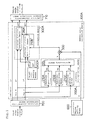
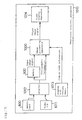
- FIG. 1 is a block diagram showing a schematic configuration of an image processing apparatus in accordance with Embodiment 1 of the present invention.
- the image processing apparatus in accordance with this embodiment is configured as a unit of carrying out the memory color correction of skin color and installed in a color printer wherein a memory card storing images taken using a digital camera is input and digital photographs are printed.
- a card reader, a JPEG development processor, a page memory, a print engine, etc. not shown, other than the devices shown in this block diagram, are present.
- input and output pixel signals are (R, G, B) signals
- luminance chromaticity signals are (L*, a*, b*).
- Numeral 100A designates a memory color correction means
- numeral 700 designates a luminance chromaticity conversion means of converting pixel signals comprising (R, G, B) into luminance chromaticity signals (L*, a*, b*)
- numeral 710 designates a luminance chromaticity inverse conversion means of converting (L*, a*, b*)* corrected using the memory color correction means 100A into (R1, G1, B1)
- numeral 600 designates a correction degree setting means of setting correction degree K depending on which memory color correction is carried out using a means not shown in this embodiment.
- the correction degree setting means 600 will be described later.
- the memory color correction means 100A comprises an intensity determination means 200A of determining correction intensity W according to (L*, a*, b*), a target color setting means 400A of setting target chromaticity (a0*, b0*) for memory color correction, a multiplication means 500 of multiplying correction intensity W by the correction degree K, and a correction means 300A of bringing the chromaticity signals (a*, b*) output from the luminance chromaticity conversion means 700 to the chromaticity values (a0*, b0*) set using the target color setting means 400A depending on the output of the multiplication means 500.
- the intensity determination means 200A comprises three function generation means 210A, 210B and 210C and a synthesizing means 220, and the correction means 300A comprises two internal division means 310A and 310B.
- the image processing apparatus in accordance with this embodiment carries out the memory color correction of an input image signal.
- colors that should be or are desired to be like these psychologically such as skin color and the green of trees
- memory colors colors that should be or are desired to be like these psychologically, such as skin color and the green of trees.
- the image processing apparatus in accordance with this embodiment corrects, for example, the human skin color of the input image signal so as to become close to the memory color.
- the input (R, G, B) signals are converted into a luminance signal L* and two chromaticity signals (a*, b*) using the luminance chromaticity conversion means 700.
- the L*, a* and b* signals are processed using the function generation means 210C, 210A and 210B formed of a look-up table (hereinafter referred to as LUT), and correction intensities WL, Wa and Wb respectively independent in axial directions are output.
- these correction intensities WL, Wa and Wb are synthesized using the synthesizing means 220 and converted into correction intensity W.
- the synthesizing means 220 in accordance with this embodiment carries out operation of outputting the minimum value of WL, Wa and Wb.
- the weight W for a skin color region can be determined fairly flexibly using the three one-dimensional function generation means 210A, 210B and 210C.
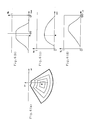
- FIGS. 2(d), 2(b) and 2(c) show an example of the LUT for the L* and (a*, b*) signals, and the positive value ranges of the correction intensities WL, Wa and Wb determine the skin color regions in respective axial directions.
- FIG.2(a) shows the skin color region determined using the three-dimensional correction intensity W synthesized using the synthesizing means 220 in the (a*, b*) plane.
- the skin color region in FIG. 2(a) is the region of the (a*, b*) plane in which the correction intensity W has a positive value.
- the skin color region is shown, but the correction intensity W is not shown.
- the size of the skin color region is determined on the basis of the statistics of various human skin colors actually photographed, and the magnitude of the weight on each axis inside the region is created by considering the pull-in degree to the target color (a0*, b0*) for the above-mentioned numerous images.
- the skin color region occupies a considerably wide range of the first quadrant of the (a*, b*) plane when various skin colors are considered; however, since the end portions of the range are set so that the correction intensity W decreases gradually, the influence to colors deviated from the skin color is relatively small, whereby no turn-back occurs in the (a*, b*) plane and continuous gradation can be obtained.
- the function generation means 210C having the characteristic of FIG. 2(d) is effective in reducing the side effects of skin color correction.
- the correction intensity W is determined for the color indicated by ⁇ is described using FIG. 2. Since the color indicated by ⁇ is fairly bright and a skin color close to yellow and a considerably dark color, the correction intensity WL in the luminance direction has the smallest value, and this becomes the correction intensity W, resulting in relatively weak correction. Since the correction intensity W is determined in consideration of not only the chromaticity signals (a*, b*) but also the luminance signal L as described above, the side effects generated when a very dark skin color is corrected can be reduced.
- the luminance signal L* is not corrected, but only the chromaticity signals (a*, b*) are corrected. Since the luminance signal is apt to be conspicuous in the disturbance in gradation visually, the change in color is apt to directly lead to side effects wherein false contours and unnatural gradation are caused owing to the disturbance in gradation; if the luminance of the skin color portion is desired to be changed, it can be changed naturally using known technologies, such as gradation correction and gamma correction, other than the memory color correction. In a similar method, it is of course possible to carry out moderate correction for luminance in a range wherein the side effects can be ignored.
- the correction means 300A in accordance with this embodiment carries out internal division operation for the chromaticity signals (a*, b*) and the target chromaticity values (a0*, b0*) using the correction intensity W according to the following expressions.
- (b1*) (1 - W)(b*) + W(b0*)
- the correction degree K set using the correction degree setting means 600 is set according to the instruction of a user via the user interface of the controller of a printer not shown. For example, in the case of an image including no persons or in the case that faithful color reproduction is desired without carrying out memory color correction, a value close to 0 is set; in other cases, a value close to 1 is set.
- the multiplication means 500 operates to adjust the correction intensity W output from the intensity determination means 200A in proportion to the above-mentioned correction degree K. For example, the multiplication means 500 adjusts the correction intensity W to the product of the above-mentioned correction degree K and the correction intensity W output from the intensity determination means 200A.
- the above-mentioned internal division operation is carried out at the correction means 300A.
- the correction degree K when the user sets the correction degree K at 0, memory color correction becomes completely inoperative. Furthermore, when the user sets the correction degree K at 1, sufficient memory color correction is carried out.
- the memory color correction of skin color is taken as an example and described; however, the embodiment can also be used for the correction of other colors as a matter of course.
- (L*, a*, b*) are used as luminance and chromaticity signals; however, other than these, numerous luminance chromaticity color spaces, such as (L*, u*, v*), (Y, Cb, Cr), (Y, R-Y, B-Y) and (Y, U, V), can be used, whereby color spaces that can be narrowed easily according to the kinds of memory colors can be used.
- the correction means 300A is configured to correct only chromaticity signals; however, it can also have a similar configuration for the luminance signal.
- the synthesizing means 220 comprises a minimum value detection circuit that outputs the minimum of the three signals; however, known various nonlinear circuits having a similar effect, such as the arithmetic product of the three correction intensities, for example, can be used.
- the correction degree setting means 600 can carry out setting by various automatic setting other than manual setting conducted by the above-mentioned user.
- a means capable of changing the magnitude of the correction intensity W depending on the magnitude of the correction degree K, not carrying out multiplication may also be used.
- a minimum value detection circuit or the like can also be used.
- the intensity determination means 200A and the correction means 300A in accordance with this embodiment are examples of color conversion means in accordance with the present invention
- the correction degree setting means 600, the intensity determination means 200A, the multiplication means 500 and the correction means 300A in accordance with this embodiment are examples of the color conversion means in accordance with the present invention
- the function generation means 210A in accordance with this embodiment is an example of a second function generation means in accordance with the present invention
- the function generation means 210B in accordance with this embodiment is an example of a third function generation means in accordance with the present invention
- the function generation means 210C in accordance with this embodiment is an example of a first function generation means in accordance with the present invention
- the correction intensity Wa in accordance with this embodiment is an example of a candidate of a second correction intensity in accordance with the present invention
- the correction intensity Wb in accordance with this embodiment is an example of a candidate of a third correction intensity in accordance with the present invention
- the correction intensity WL in accordance with this embodiment is an
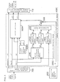
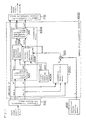
- FIG. 3 is a block diagram showing a schematic configuration of an image processing apparatus in accordance with Embodiment 2 of the present invention.
- This embodiment has uses similar to those of the above-mentioned Embodiment 1, and is configured as a unit of carrying out the memory color correction of skin color and installed inside a color printer.
- a card reader, a JPEG development processor, a page memory, a print engine, etc., not shown, other than the devices shown in this block diagram, are present.
- input and output pixel signals are (R, G, B) signals
- luminance chromaticity signals are (L*, a*, b*).
- Numeral 100B designates a memory color correction means
- numeral 700 designates a luminance chromaticity conversion means
- numeral 710 designates a luminance chromaticity inverse conversion means
- numeral 600 designates a correction degree setting means; the same components as those in accordance with Embodiment 1 are designated using the same reference numerals, and their detailed descriptions are omitted.
- the memory color correction means 100B comprises an intensity determination means 200B of determining correction intensity W according to (L*, a*, b*), a target color setting means 400A of setting target chromaticity (a0*, b0*) for memory color correction, a multiplication means 500 of multiplying correction intensity W by correction degree K, and a correction means 300A of bringing the chromaticity signals (a*, b*) output from the luminance chromaticity conversion means 700 to the chromaticity values (a0*, b0*) set using the target color setting means 400A depending on the output of the multiplication means 500.
- the intensity determination means 200B comprises a two-dimensional function generation means 211, a function generation means 210C and a synthesizing means 221.
- correction intensity WL is output from the function generation means 210C formed of an LUT, and with respect to the chromaticity signals (a*, b*), correction intensity Wc is output from the two-dimensional function generation means 211.
- the synthesizing means 221 carries out operation of outputting the minimum value of WL and Wc.
- correction means 300A and the correction degree setting means 600 are similar to those in accordance with Embodiment 1 and their descriptions are omitted.
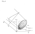
- FIG. 4 is an explanatory view showing an example of the two-dimensional function generation means 211 of generating the correction intensity Wc in the (a*, b*) plane.
- the ellipse drawn in a thick line and represented by region 2 in the figure indicates a skin color region, and smaller ellipses indicate correction intensity Wc using contour lines.
- the region 2 is a region wherein the correction intensity Wc has a positive value.
- the upper left graph one-dimensionally shows the cross section of the ellipse sectioned in the longitudinal-axis direction of the ellipse.
- Mark ⁇ in the figure indicates the target color (a0*, b0*).
- the rectangle drawn in a dotted line and represented by region 1 shows the skin color region described in Embodiment 1 for the purpose of comparison.
- the two-dimensional function generation means 211 in accordance with Embodiment 2 is suited for narrowing various skin colors to a necessary and sufficient form. Furthermore, as a skin color becomes nearer to the end of the skin color region indicated by the ellipse drawn in the thick line, the correction intensity Wc becomes smaller gradually; hence, even if a color other than the skin color desired to be corrected is present inside this region, its influence is relatively small. Still further, no turn-back occurs in the (a*, b*) plane, and continuous gradation can be obtained.
- a shape obtained by horizontally cutting an inclined elliptical cone at a predetermined height is obtained by calculation in advance and stored in the two-dimensional LUT.
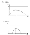
- FIG. 18(a) is an explanatory view of the turn-back in the case of one dimension wherein one output corresponds to two outputs.
- FIG. 8(b) is an explanatory view of the turn-back in the (a*, b*) plane.
- the memory color correction of skin color is taken as an example and described; however, the embodiment can also be used for correction of other colors as a matter of course.
- (L*, a*, b*) are used as luminance and chromaticity signals; however, other than these, numerous luminance chromaticity-based color spaces, such as (L*, u*, v*), (Y, Cb, Cr), (Y, R-Y, B-Y) and (Y, U, V), can be used, whereby color spaces that can be narrowed easily according to the kinds of memory colors can be used.
- the two-dimensional function generation means has been described using the function of an elliptical shape; however, a free shape can be used actually depending on the distribution of a target color, and as a function generating method, a method of using mathematical expression calculation, other than the two-dimensional LUT, can also be used.
- the correction means 300A is configured to correct only chromaticity signals; however, it can also have a similar configuration for the luminance signals.
- the synthesizing means 221 comprises a minimum value detection circuit that outputs the minimum of the two signals; however, known various nonlinear circuits having a similar effect, such as an arithmetic product of the two correction intensities, for example, can be used.
- the correction degree setting means 600 can carry out setting by various automatic setting other than manual setting conducted by the above-mentioned user.
- a means capable of changing the magnitude of the correction intensity W depending on the magnitude of the correction degree K, not carrying out multiplication may also be used.
- a minimum value detection circuit or the like can also be used. The details of the correction degree setting means 600 will be described later.
- the intensity determination means 200B and the correction means 300A in accordance with this embodiment are examples of the color conversion means in accordance with the present invention
- the correction degree setting means 600, the intensity determination means 200B and the correction means 300A in accordance with this embodiment are examples of the color conversion means in accordance with the present invention
- the function generation means 210C in accordance with this embodiment is an example of the first function generation means in accordance with the present invention
- the correction intensity WL in accordance with this embodiment is an example of the first correction intensity in accordance with the present invention
- the correction intensity Wc in accordance with this embodiment is an example of the second correction intensity in accordance with the present invention
- the correction intensity W in accordance with this embodiment is an example of the correction intensity in accordance with the present invention.
- FIG. 5 is a block diagram showing a schematic configuration of an image processing apparatus in accordance with Embodiment 3 of the present invention.
- This embodiment has uses similar to those of the above-mentioned embodiments, and is configured as a unit of carrying out the memory color correction of sky blue.
- a card reader, a JPEG development processor, a page memory, a print engine, etc., not shown, other than the devices shown in this block diagram, are present.
- input and output pixel signals are (R, G, B) signals
- luminance chromaticity signals are (L*, a*, b*).
- Numeral 100C designates a memory color correction means
- numeral 700 designates a luminance chromaticity conversion means
- numeral 710 designates a luminance chromaticity inverse conversion means
- numeral 600 designates a correction degree setting means; the same components as those in accordance with the above-mentioned embodiments are designated using the same reference numerals, and their detailed descriptions are omitted.
- the memory color correction means 100C comprises an intensity determination means 200C of determining correction intensity W according to (L*, a*, b*), a target color setting means 400A of setting target chromaticity (a0*, b0*) for sky blue, and a correction means 300A of bringing the signals to the chromaticity values (a0*, b0*) set using the target color setting means 400A depending on the correction intensity W.
- Numeral 230 designates a polar coordinate conversion means of converting the chromaticity signals (a*, b*) into hue and sat represented in the polar coordinate system
- numeral 210D designates a function generation means of outputting correction intensity Wh on the hue axis
- 210E designates a function generation means of outputting correction intensity Ws on the saturation axis
- 210C designates a function generation means of outputting correction intensity WL on the luminance axis
- numeral 222 designates a synthesizing means of synthesizing three correction intensities.
- correction intensity WL is output using the function generation means 210C formed of an LUT, and the chromaticity signals (a*, b*) are converted using the polar coordinate conversion means 230 such that hue is represented by angle and sat is represented by length.
- Hue is converted into correction intensity Wh in the hue direction using the function generation means 210D, and sat is converted into a correction intensity Ws in the saturation direction using the function generation means 210E.
- FIGS. 6(d), 6(b) and 6(c) show examples of the LUTs constituting function generation means for luminance L*, hue and sat, respectively.
- the positive value ranges of the correction intensities WL, Wh and Ws determine the sky blue regions in respective axial directions.
- FIG. 6(a) shows the sky blue region determined using the three-dimensional correction intensity W synthesized using the synthesizing means 222 in the (a*, b*) plane, the thick line indicates the sky blue region, and the correction intensity W is shown using thin contour lines.
- Mark ⁇ indicates a target color (a0*, b0*).
- the size of the sky blue region is determined on the basis of the statistics of extracted colors obtained by extracting sky portions from various landscape images taken actually.
- colors with a wide range of hue, exceeding 90 degrees in hue, from a color close to cyan to a color close to violet, are present, and colors with a wide range of saturation, from a color close to an achromatic color of an obscured sky to a bright color of a clear sky in a southern country are present.
- the setting of the correction intensity in the chromaticity plate in the orthogonal coordinate system and the setting in the polar coordinate system are different significantly; hence, it is almost impossible to carry out the setting in the orthogonal coordinate system, and it is found that the setting should preferably be carried out in the polar coordinate system.
- the end portion of the fan-shaped range is set so that the correction intensity decreases gradually, whereby the wide range of sky blue can be covered properly, and natural gradation with no turn-back can be attained.
- the function generation means 210C having the characteristic of FIG. 6(d) is effective in reducing the side effects of the memory color correction of sky blue. It is actually confirmed that the influence on objects of dark blue, not sky blue, is relieved significantly by the effect of the function generation means 210C.
- the luminance signal L* is not corrected, but only the chromaticity signals (a*, b*) are corrected. Since the luminance signal is apt to be conspicuous in the disturbance in gradation visually, the change in color is apt to directly lead to side effects wherein false contours and unnatural gradation are caused by the disturbance in gradation; if the luminance of the sky blue portion is desired to be changed, it can be changed naturally using known technologies, such as gradation correction and gamma correction, other than the memory color correction. It is of course possible to carry out moderate correction for luminance in a range wherein the side effects can be ignored.
- the memory color correction of sky blue is taken as an example and described; however, the embodiment can be used for the correction of other colors as a matter of course.
- the green of plants, such as trees and grass has a wide range in hue, as in sky blue, and also has a wide range in saturation.
- (L*, a*, b*) are used as luminance and chromaticity signals; however, other than these, numerous luminance chromaticity color spaces, such as (L*, u*, v*), (Y, Cb, Cr), (Y, R-Y, B-Y) and (Y, U, V), can be used, whereby color spaces that can be narrowed easily according to the kinds of memory colors can be used.
- the correction means 300A is configured to correct only chromaticity signals; however, it can also have a similar configuration for the luminance signals.
- the synthesizing means 222 comprises a minimum value detection circuit that outputs the minimum of the two signals; however, known various nonlinear circuits having a similar effect, such as an arithmetic product of the two correction intensities, for example, can be used.
- the correction degree setting means 600 can carry out setting by various automatic setting other than manual setting conducted by the above-mentioned user.
- a means capable of changing the magnitude of the correction intensity W depending on the magnitude of the correction degree K, not carrying out multiplication may also be used.
- a minimum value detection circuit or the like can also be used. The details of the correction degree setting means 600 will be described later.
- the intensity determination means 200C and the correction means 300A in accordance with this embodiment are examples of the color conversion means in accordance with the present invention
- the correction degree setting means 600, the intensity determination means 200C and the correction means 300A in accordance with this embodiment are examples of the color conversion means in accordance with the present invention
- the function generation means 210C in accordance with this embodiment is an example of the first function generation means in accordance with the present invention
- the function generation means 210D in accordance with this embodiment is an example of the second function generation means in accordance with the present invention
- the function generation means 210E in accordance with this embodiment is an example of the third function generation means in accordance with the present invention
- the correction intensity WL in accordance with this embodiment is an example of a candidate of the first correction intensity in accordance with the present invention
- the correction intensity Wh in accordance with this embodiment is an example of a candidate of the second correction intensity in accordance with the present invention
- the correction intensity Ws in accordance with this embodiment is an example of the third correction intensity in accordance
- FIG. 7 is a block diagram showing a schematic configuration of an image processing apparatus in accordance with Embodiment 4 of the present invention. This embodiment is configured as a unit of carrying out the memory color correction of sky blue, as in Embodiment 3.
- Numeral 100D designates a memory color correction means
- numeral 700 designates a luminance chromaticity conversion means
- numeral 710 designates a luminance chromaticity inverse conversion means
- the memory color correction means 100D comprises the following.
- Numeral 200C designates an intensity determination means
- numeral 300B designates a correction means of carrying out correction in the polar coordinate system
- numeral 400B designates a target color setting means of setting a target color, that is, target hue hue0 and target saturation sat0, in the polar coordinate system.
- correction means 300B comprises the following.
- Numeral 320 designates a polar coordinate conversion means
- 310A and 310B designate internal division means of internally dividing the hue and sat output from the polar coordinate conversion means 320
- numeral 330 designates an orthogonal coordinate conversion means of carrying out inverse conversion from the polar coordinate system to the orthogonal coordinate system.
- the intensity determination means 200C similar to that of Embodiment 3 first outputs the correction intensity W of a sky blue region on the basis of the chromaticity signals (a*, b*) and the luminance signal L* output from the luminance chromaticity conversion means 700. At the same time, the chromaticity signals (a*, b*) are converted into hue and sat using the polar coordinate conversion means 230.
- the internal division means 310A internally divides the hue signal hue and the hue signal hue0 of the target color using the correction intensity W and outputs as hue1.
- the internal division means 310B internally divides the saturation signal sat and the saturation signal sat0 of the target color using the correction intensity W and outputs as sat1.
- hue and sat, not corrected are output when W is 0; when W is 1, hue0 and sat0, representing the target sky blue, are output.
- the hue1 and sat1 subjected to memory color correction are returned to the chromaticity signals (a1*, b1*) subjected to memory color correction using orthogonal coordinate conversion means 330.
- the region of sky blue has a very wide range.
- the correction intensity is obtained using the hue and saturation axes obtained when chromaticity values are subjected to polar coordinate conversion in Embodiment 3; however, in a similar way, the correction means 300B is also required to carry out natural correction of sky blue having the wide range.
- FIG. 8 is an explanatory view showing the effect of the correction means 300B in accordance with this embodiment.
- Mark ⁇ indicates a target color
- mark ⁇ indicates an input color.
- the correction means 300A in accordance with the above-mentioned embodiments is used, an internal division of 50% in the orthogonal coordinate system is obtained, and the color indicated by mark ⁇ is output.
- the hue becomes 50% in terms of angle, and the saturation is internally divided into 50% in terms of distance from the origin, whereby the color indicated by mark ⁇ is output.
- the correction amount of hue becomes insufficient, and the saturation always becomes fairly low.
- the luminance signal L* is not corrected either; however, moderate correction can also be carried out for luminance using a similar method in a range of not causing side effects.
- the memory color correction of sky blue is taken as an example and described; however, the embodiment can also be used for correction of other colors as a matter of course.
- the memory color correction of the green of plants, such as trees and grass excellent results can also be obtained as in the case of sky blue.
- (L*, a*, b*) are used as luminance and chromaticity signals; however, other than these, numerous luminance chromaticity color spaces, such as (L*, u*, v*), (Y, Cb, Cr), (Y, R-Y, B-Y) and (Y, U, V), can be used, whereby color spaces that can be narrowed easily according to the kinds of memory colors can be used.
- the adjustment of the correction degree K using the correction degree setting means is omitted; however, the adjustment can be added using a method similar to that of the above-mentioned embodiment as a matter of course.
- the details of the correction degree setting means 600 will be described later.
- the intensity determination means 200C and the correction means 300B in accordance with this embodiment are examples of the color conversion means in accordance with the present invention
- the correction degree setting means 600, the intensity determination means 200C, the multiplication means 500 and the correction means 300B in accordance with this embodiment are examples of the color conversion means in accordance with the present invention
- the polar coordinate conversion means 320 in accordance with this embodiment is an example of a second polar coordinate conversion means in accordance with the present invention.
- FIG. 9 is a block diagram showing a schematic configuration of an image processing apparatus in accordance with Embodiment 5 of the present invention. This embodiment is configured as a unit of carrying out the memory color correction of sky blue, as in Embodiments 3 and 4.
- Numeral 100E designates a memory color correction means
- numeral 700 designates a luminance chromaticity conversion means
- numeral 710 designates a luminance chromaticity inverse conversion means
- the memory color correction means 100E comprises the following.
- Numeral 201C and 202C each designate an intensity determination means
- numeral 300B designates a correction means of carrying out correction in the polar coordinate system
- numeral 400B designates a target color setting means of setting a target color, that is, target hue hue0 and target saturation sat0.
- correction means 300B comprises a polar coordinate conversion means 320, internal division means 310A and 310B and an orthogonal coordinate conversion means 330.
- the image processing apparatus in accordance with Embodiment 5 is characterized in that it is equipped with two separate means, an intensity determination means 201C of determining correction intensity W1 for carrying out hue correction and an intensity determination means 202C of determining correction intensity W2 for carrying out saturation correction using the correction means 300B.
- the intensity determination means 201C and the intensity determination means 202C are the same in configuration as the intensity determination means 200C shown in FIG. 5, but are different in the contents of the LUTs of the function generation means 210C, 210D and 210E.
- the memory color correction of sky blue operates so that the hue close to cyan is rotated in the positive direction, and the hue close to violet is rotated in the negative direction, whereby the sky blue is pulled to the hue of the target blue.
- the saturation of sky blue having too high saturation is lowered, and the saturation of sky blue having too low saturation is raised, whereby the sky blue is pulled so as to have the saturation of the target color.
- the above-mentioned saturation region is excluded from the correction range.
- the color of a cloudless sky is subjected to correction and is changed so as to have the target hue; however, the color of the sky slightly appearing from between the boundaries of clouds remains in the original color; hence, the naturalness as an image is impaired, the image becomes an artificial composite image, and the image quality improving effect of the memory color correction is impaired.
- the intensity determination means 201C for hue correction sets the correction intensity W1 being used for carrying out correction in a wide range from the above-mentioned low saturation region to the high saturation region
- the intensity determination means 202C of saturation correction sets the correction intensity W2 being used for excluding the low saturation region from the target of correction. It is effective to exclude the high saturation region from the target of correction at the same time, from a viewpoint of not lowering the saturation of bright sky blue.
- FIG. 10(a) shows an example of the saturation-use function generation means 210E constituting the intensity determination means 201C
- FIG. 10(b) shows an example of the saturation-use function generation means 210E constituting the intensity determination means 202C.
- the range of saturation sat wherein the intensity has a positive value in the saturation-use function generation means 210E of the intensity determination means 201C of generating intensity W1 for carrying out hue correction is wider than that in the saturation-use function generation means 210E of the intensity determination means 202C of generating intensity W2 for carrying out saturation correction.
- hue-use function generation means 210C and the luminance-use function generation means 210E those shown in FIGS. 6(b) and 6(d) are used. Their effects can be raised further by their respective independent optimization as a matter of course.
- the luminance signal L* is not corrected either; however, moderate correction can also be carried out for luminance using a similar method in a range of not causing side effects.
- the memory color correction of sky blue is taken as an example and described; however, the embodiment can also be used for correction of other colors as a matter of course.
- the memory color correction of the green of plants, such as trees and grass excellent results can also be obtained as in the case of sky blue.
- (L*, a*, b*) are used as luminance and chromaticity signals; however, other than these, numerous luminance chromaticity color spaces, such as (L*, u*, v*), (Y, Cb, Cr), (Y, R-Y, B-Y) and (Y, U, V), can be used, whereby color spaces that can be narrowed easily according to the kinds of memory colors can be used.
- the adjustment of the correction degree K using the correction degree setting means is omitted; however, the adjustment can be added using a method similar to that of the above-mentioned embodiment as a matter of course.
- the intensity determination means 202C, the intensity determination means 201C and the correction means 300B in accordance with this embodiment are examples of the color conversion means in accordance with the present invention;
- the correction intensity W1 in accordance with this embodiment is an example of a hue correction intensity in accordance with the present invention;
- the correction intensity W2 in accordance with this embodiment is an example of a saturation correction intensity in accordance with the present invention;
- the polar coordinate conversion means 320 in accordance with this embodiment is an example of the second polar coordinate conversion means in accordance with the present invention;
- the internal division operation means 310A in accordance with this embodiment is an example of the hue correction means in accordance with the present invention;
- the internal division operation means 310B in accordance with this embodiment is an example of the saturation correction means in accordance with the present invention.
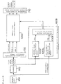
- FIG. 11 is a block diagram showing a schematic configuration of an image processing apparatus in accordance with Embodiment 6 of the present invention. This embodiment is configured as a unit of carrying out the memory color correction of sky blue, as in Embodiments 3, 4 and 5.
- numeral 800 designates a memory card in which photographed images and photographic information obtained at the time of photographing are recorded
- numeral 900 designates a memory in which images read out from the memory card 800 are stored
- numeral 700 designates a luminance chromaticity conversion means
- numeral 600A designates a correction degree setting means
- numeral 100F designates a memory color correction means
- numeral 710 designates a luminance chromaticity inverse conversion means
- the correction degree setting means 600A comprises a sky image identification means 610A of obtaining reliability TSa of including the sky in an image according to an image signal, a photographic information identification means 620A of obtaining reliability TSb of including the sky in an image according to the photographic information, and a correction degree determination means 630A of determining correction degree K according to the reliability TSa output from the sky image identification means 610A and the reliability TSb output from the photographic information identification means 620A.
- the sky image identification means 610A comprises a region information calculation means 611 of calculating a characteristic amount of each region obtained by dividing an image vertically and horizontally, a sky region candidate detection means 612 of judging wherein each region is a sky region candidate or not, and a sky region distribution judgment means 613 of obtaining the reliability TSa of including the sky according to the distribution of the sky region candidates.
- Photographed image data recorded in the memory card 800 is divided into an image signal and photographic information, and the image signal is recorded in the memory 900, and the photographic information is input to the photographic information identification means 620A.
- the photographic information includes various conditions and the preset values of a camera during photographing, which are recorded in the memory card 800 using the camera together with the image signal during photographing of an image; for example, incidental information regarding photographing conditions specified in Exif serving as an image file format standard for digital still cameras corresponds to this.
- the photographic information identification means 620A judges the possibility of including the sky in an object according to the photographic information. At this time, the distance to the object, the light source during photographing, photographic scene information and photographing time are used as the photographic information. In the case that only some of the above are recorded as the photographic information, identification is carried out according to only the photographic information.
- recognition is made as to whether the distance to the object is either one of macro view, near view, distant view and unknown view, and in the cases other than macro view, it is judged that there is a possibility that the sky may be included.
- photographic scene information recognition is made as to whether the scene is a night scene or not. In the cases other than a night scene, it is judged that there is a possibility that the sky may be included.
- photographing time recognition is made as to whether the time is either daytime or nighttime.
- the photographing time cannot be used directly for the judgment as to whether the sky is included or not; however, in the case of nighttime, it is judged that the sky is not included so that side effects on an image of the sky photographed during nighttime is avoided in memory color correction.
- a fluorescent lamp, an incandescent lamp and the like are included as a light source that can be judged as indoor light; however, a certain type of fluorescent lamp has a color temperature close to that of daylight; in this case, it is difficult to estimate the light source.
- the incandescent lamp relatively significantly differs from daylight in terms of color temperature, and its estimation is easy. In the case that the light source during photographing is significantly different from daylight in terms of color temperature as described above, there is a high possibility that the light source of a camera may be estimated properly, and it can thus be judged that the possibility of including the sky is significantly low.
- the reliability TSb of including the sky in an image according to the final photographic information is obtained using the fuzzy inference. Examples of fuzzy control rules at this time are shown below.
- the fuzzy inference has been used to obtain the reliability TSb of including the sky in an image according to the photographic information
- a means capable of changing the magnitude of the reliability TSb by reflecting multiple pieces of photographic information may be used.
- the table of the reliability TSb for the combination of all the photographic information may also be used.
- the brightness of an object is estimated according to the shutter speed and the aperture value; in the case that the brightness is higher than a certain value, it can be judged that there is a possibility that the sky may be included in the object.
- the brightness to be judged according to the photographing time can also be changed.
- the fact that the brightness to be judged according to the photographing time is changed means that the threshold value for judging whether the photographing environment is bright or not is changed.
- the threshold value for judging whether the photographing environment is bright or not can be set higher, and during nighttime, this threshold value can be set lower.
- the photographing time is divided into morning time, daytime, evening time and nighttime, and the operation of the memory color correction may be switched respectively.
- the judgment of morning time and evening time can be carried out by obtaining the sunrise time and sunset time of a photographing date.
- the sunrise time and sunset time can also be obtained regardless of district using the GPS information regarding the photographing site.
- the identification may be carried out using all the above-mentioned photographic information, or the identification may be carried out using part of the photographic information.
- the region information calculation means 611 roughly divides an image signal output from the memory 900 into regions vertically and horizontally according to the coordinates in the image, and calculates region information comprising the average luminance, average hue and average saturation for each region. At this time, the calculation is carried out while the image signal inside the region is thinned out for high-speed processing.
- the sky region candidate detection means 612 judges whether a sky region is present in each region according to the region information, that is, the output signal of the region information calculation means 611. More specifically, average R value Rmean, average G value Gmean and average B value Bmean are calculated in each region according to the average luminance Lmean, average hue and average saturation.
- the detection is carried out in a range wider than the range of the color to be actually subjected to color correction using the memory color correction means 100F, and the processing is easy; because of these reasons, the sky region candidates are judged by comparing Rmean, Gmean and Bmean.
- sky region candidate C is judged according to the next logical expression for each region using the threshold value Lth of a certain luminance level.
- C (Bmean > Rmean) && (Bmean > Gmean) && (Lmean > Lth)
- && means logical AND operation.
- A&&B (A and B are logical expressions) becomes 1 when both A and B are 1, and becomes 1 when both of A and B are not 1 and when either one of A and B is not 1.
- a simple method of using the magnitude relationship of the average values (R, G, B) for sky region candidate detection is adopted; however, other than this, it may be possible to adopt a method wherein the average (R, G, B) values are weighted and then compared or a method wherein a function similar to the narrowing of the target color region in the above-mentioned embodiments is used.
- luminance chromaticity color spaces such as (L*, a*, b*), (L*, u*, v*), (Y, Cb, Cr), (Y, R-Y, B-Y) and (Y, U, V), other than (R, G, B), can also be used.
- the degree of identifying whether a roughly divided region is the sky or not can be fine-adjusted by adjusting the weights, whereby the accuracy of identifying whether the roughly divided region is the sky or not can be raised by setting proper weights.
- the functions used in the above-mentioned embodiments are applied to the average luminance Lmean, average hue and average saturation in a roughly divided region, respectively, to obtain the respective intensities of the average luminance Lmean, average hue and average saturation.
- the minimum value of these intensities is used as the overall intensity of the average luminance Lmean, average hue and average saturation.
- the overall intensity has a positive value, it is judged that the sky is included in the roughly divided region; in the case that this overall intensity is 0, it is judged that the sky is not included in the roughly divided region. Whether the roughly divided region includes the sky or not can also be identified by using this method.
- the sky region distribution judgment means 613 calculates the product of the sky region candidate information output from the sky region candidate detection means 612 and a predetermined sky region judgment mask for each region, and the reliability TSa of including the sky in an image according to the image information is obtained from the sum thereof.
- FIG. 12(c) shows an example of the sky region judgment mask in which these are reflected.
- the sky region judgment mask is formed of binary values, and the lower central portion of the image is excluded from the target for sky region judgment; however, for example, it may be possible to use a configuration wherein each region is weighted so that the upper portion of the image is weighted heavily and the lower portion is weighted lightly.
- the sky region judgment mask can also be changed according to the information.
- the operation of the sky region candidate detection means 610A can also be changed according to the judgment results from the photographic information. For example, since the sky is not used as a main object usually, a sky region judgment mask of using regions other than the object region as the sky region judgment target can also be obtained by using information regarding the position and region of the object in the photographic information.
- FIG. 12(a) shows a color image to be input, and this case is an conceptual view of a landscape image wherein the sky is photographed in the upper portion of the image and a lake is photographed in the lower portion of the image.
- FIG. 12(b) shows the result obtained when the image is divided into regions of three blocks in the vertical direction and four blocks in the horizontal direction and sky region candidate detection is carried out.
- FIG. 12(c) shows a sky region judgment mask, and FIG. 12(d) shows the result obtained when this judgment mask is applied to the result of FIG. 12(b).
- the correction degree determination means 630A determines the final correction degree K as the product of the reliability TSa of including the sky in the image according to the image signal output from the sky image identification means 610A and the reliability TSb of including the sky in the image according to the photographic information output from the photographic information identification means 620A.
- the photographic information identification means 620A does not output the reliability TSb, and the correction degree determination means determines the correction degree K by using only the reliability TSa.
- the luminance chromaticity conversion means 700 converts the image signal output from the memory into luminance chromaticity signals.
- the memory color correction means 100F carries out memory color correction for the luminance chromaticity signals output from the luminance chromaticity conversion means 700 depending on the correction degree K output from the correction degree determination means 630A.
- the correction degree determination means 630A may use continuous values as the correction degree K, as in this embodiment, or may turn on/off memory color correction by adopting binarization using a threshold value. In the case of a means capable of changing the magnitude of the correction degree K depending on the magnitude of the reliabilities TSa and Tsb, multiplication may not be used.
- the correction degree K is used for memory color correction in this embodiment; however, other than this, it can also be used for white balance adjustment and gradation correction. In this case, it becomes possible that proper effects are obtained by changing information derived from the photographic information and image depending on the contents of image processing to be carried out.
- a configuration in the case that sky blue is corrected is shown; however, correction of other colors can also be carried out by properly configuring the image identification means and the photographic identification means.
- This embodiment can be applied to, for example, a case of correcting the green of plants, such as trees and grass.
- multiple colors in one image can also be corrected by using a configuration having multiple correction degree setting means and multiple memory color correction means.
- correction degree setting means 600A and the memory color correction means 100F in accordance with this embodiment are examples of the color conversion means in accordance with the present invention.
- the sky image identification means 610A in accordance with this embodiment is an example of the image identification means in accordance with the present invention.
- FIG. 13 is a block diagram showing a schematic configuration of an image processing apparatus in accordance with Embodiment 7 of the present invention. This embodiment is configured as a unit of carrying out the memory color correction of skin color, as in the above-mentioned Embodiments 1 and 2.
- numeral 800 designates a memory card in which photographed images and photographic information obtained at the time of photographing are recorded
- numeral 900 designates a memory in which images read out from the memory card 800 are stored
- numeral 700 designates a luminance chromaticity conversion means
- numeral 600B designates a correction degree setting means
- numeral 100G designates a memory color correction means
- numeral 710 designates a luminance chromaticity inverse conversion means
- the correction degree setting means 600B comprises a sky image identification means 610B of obtaining reliability TPa of including a person in an image according to an image signal, a photographic information identification means 620B of obtaining reliability TPb of including a person in an image according to photographic information, and a correction degree determination means 630B of determining correction degree K according to the reliability TPa output from the sky image identification means 610B and the reliability TPb output from the photographic information identification means 620B.
- Photographed image data recorded in the memory card 800 is divided into an image signal and photographic information, and the image signal is recorded in the memory 900, and the photographic information is input to the photographic information identification means 620B.
- the photographic information includes various conditions and the preset values of a camera during photographing, which are recorded in the memory card 800 using the camera together with the image signal during photographing of an image; for example, incidental information regarding photographing conditions specified in Exif serving as an image file format standard for digital still cameras corresponds to this.
- the photographic information identification means 620B judges the possibility of including a person in an object according to the photographic information. At this time, photographic scene information and the distance to the object are used as the photographic information.
- the photographic scene information is a person, it is judged that there is a high possibility that a person may be included in an object.
- the distance to an object is judged as macro photographing or distant view, it is judged that there is a low possibility that a person may be included in the object as an object. This is because in macro photographing, a small object is photographed, and the object is rarely a person, and because even if a person is photographed in distant view, its rate in the image is small, and it is estimated that the person is not a main object.
- the reliability TPb of including a person in an image according to final photographic information is obtained on the basis of the fuzzy inference as in the above-mentioned Embodiment 6 since there is a possibility that a person may be included in an object obtained from respective photographic information.
- the identification may be carried out using all the above-mentioned photographic information, or the identification may be carried using part of the photographic information.
- the person image identification means 610B obtains the reliability TPa of including a person in an object according to an input image signal. For this purpose, a method wherein an image is divided into multiple regions and the judgment as to whether the color in each region is skin color or not can be adopted, as in Embodiment 6, or various known means of making judgment on the basis of the distribution of colors included in an image and the like can be used.
- the target regions of an image subjected to person recognition can be set according to the information indicating the position and region of an object and the information of the distance to the object in the photographic information.
- the correction degree determination means 630B determines the final correction degree K as the product of the reliability TPa of including a person in the image according to the image information output from the person image identification means and the reliability TPb of including a person in the image according to the photographic information output from the photographic information identification means 620B.
- the photographic information identification means 620A does not output the reliability TPb, and the correction degree determination means determines the correction degree K by using only the reliability TPa.
- the correction degree K may be binarized using a threshold value, or a means other than multiplication may also be used.
- the luminance chromaticity conversion means 700 converts the image signal output from the memory into luminance chromaticity signals.
- the memory color correction means 100G carries out memory color correction for the luminance chromaticity signals output from the luminance chromaticity conversion means 700 depending on the correction degree K output from the correction degree determination means 630B.
- the correction degree K is used for memory color correction in this embodiment; however, other than this, it can also be used for white balance adjustment and gradation correction. In this case, it becomes possible that proper effects are obtained by changing information derived from the photographic information and image depending on the contents of image processing to be carried out.
- multiple colors in one image can also be corrected by using a configuration having multiple correction degree setting means and multiple memory color correction means.
- correction degree setting means 600B and the memory color correction means 100G in accordance with this embodiment are examples of the color conversion means in accordance with the present invention; and the person image identification means 610B in accordance with this embodiment is an example of the image identification means in accordance with the present invention.
- the contents described in the above-mentioned embodiments are not limited to hardware mounting but can be configured by software processing as a matter of course.
- the software processing is not limited to only real-time processing; for example, a configuration wherein the results obtained by preprocessing in accordance with the above-mentioned embodiments are stored in a three-dimensional look-up table (3DLUT) in which R, G and B are referred to as addresses and the 3DLUT is referred to during real-time processing, such as printing, is possible as a matter of course.
- 3DLUT three-dimensional look-up table
- image processing results including memory color correction can be obtained without enlarging the scale of hardware by storing the results obtained when the memory color correction described in this embodiment is carried out together in the 3DLUT being used for other purposes, such as color correction for printing.
- conformation to the correction degree being given in real time can be attained by internally dividing the respective reference results of an LUT including memory color correction and an LUT not including memory color correction by the correction degree.
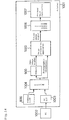
- FIGS. 14 to 17 are configuration diagrams of devices incorporating an image processing apparatus in accordance with this embodiment.
- Embodiment 8 application examples in which the image processing apparatuses described in the above-mentioned respective embodiments are incorporated in various devices will be described.
- the components described in the above-mentioned respective embodiments are designated using the same numerals, and their descriptions are omitted.
- FIG. 14 shows a printer 1001
- FIG. 15 shows a television receiver (or projector) 1010
- FIG. 16 shows a video movie camera (or digital camera) 1020
- FIG. 17 shows a portable telephone 1030.
- the image processing apparatuses described in the above-mentioned respective embodiments are incorporated. These devices will be described below.
- the printer 1001 is an apparatus of printing input image data transmitted from a personal computer (hereinafter referred to as PC) 1002 on printing media, such as paper media.
- PC personal computer
- the printer 1001 comprises a memory card 800, a memory 900, an image processing apparatus 1000, a PC I/F 1003, a selector 1004, a color conversion means 1006 and a printer head controller 1007.
- the memory card 800 and the memory 900 have been described in the above-mentioned embodiments.
- the image processing apparatus 100 is the image processing apparatus described in either one of the above-mentioned embodiments.
- the PC I/F 1003 is an interface through which commands and data, such as image signals, are transmitted between the printer driver, not shown, of the PC 1002 and the printer 1001.
- the selector 1004 is a means of carrying out switching as to whether image data is input from the memory card 800 or image data is input from the PC 1002 via the PC I/F 1003.
- the color conversion means 1006 is a means of converting output image signals serving as color signals, such as RGB, subjected to memory color correction using the image processing apparatus 1000 into CMY signals serving as print data.
- C, M and Y are cyan, magenta and yellow, corresponding to the three primary colors in the printer.
- the printer head controller 1007 is a means of controlling the printer head, not shown, of the printer 1001.
- the PC I/F 1003 receives the transmitted image data and outputs the data to the selector 1004.
- the selector 1004 receives the image data transmitted from the PC I/F 1003 and stores the data in the memory 900. In addition, the selector 1004 outputs various pieces of photographic information stored in the header of the image data, for example. As the various pieces of photographic information, the various pieces of photographic information described in the header portion of an image file created using the digital camera are used. In addition, in the case that printing is carried out from the PC 1002, the setting (photo, CG, graph, etc.) of the printer driver of the PC 1002 is also used as photographic information. This setting of the printer driver is also output to the image processing apparatus 1000. The image processing apparatus 1000 obtains a correction degree by also using this kind of information other than pixel signals.
- the image processing apparatus 1000 reads an input image signal from the memory 900 and carries out memory color conversion, described in the above-mentioned embodiments, for the input image signal by also using the photographic information output from the selector 1004.
- the correction degree described in the above-mentioned embodiments can be determined by also using the setting information of the printer driver. For example, in the case that the setting of the printer driver is photo, the correction degree obtained in the above-mentioned embodiments is directly used, and in the case of CG or graph, the correction degree is set at 0 or at a smallest value.
- the image processing apparatus 1000 outputs an image signal subjected to memory color conversion to the color conversion means 1006 as an output image signal.
- the color conversion means 1006 converts the output image signal output from the image processing apparatus 1000 and serving as color signals, such as RGB, into CMY signals serving as print data, and the image signal converted into the CMY signals is printed on printing media using the printer head, not shown, of the printer 1001 under the control of the printer head controller 1007.
- the selector 1004 reads the image data stored in the memory card 800, stores the data in the memory 900 and outputs various photographic information described in the header portion of an image file created using the digital camera to the image processing apparatus 1000.
- the setting information of the printer driver is not used. Except for this, the subsequent operation is similar to that in the case that image data is transmitted from the PC 1002, and its detailed descriptions are omitted.
- the printer 1001 in accordance with this embodiment is an example of a printer apparatus in accordance with the present invention
- the PC I/F 1003 in accordance with this embodiment is an example of an input means in accordance with the present invention
- the printer head controller 1007 in accordance with this embodiment is an example of a printing means in accordance with the present invention.
- the television receiver (or projector) 1010 shown in FIG. 15 will be described.
- video data received using the receiving circuit of receiving broadcast waves is input to a video I/F 1011.
- image data transmitted from a PC is input to the video I/F 1011.
- the image data transmitted from an apparatus other than the PC such as a video cassette recorder or a DVD player, may also be input to the video I/F 1011.
- the video display apparatus 1014 thereof comprises a cathode-ray tube, a liquid crystal display apparatus, a plasma display apparatus or the like, and in the case of the projector, it comprises a projection display apparatus or the like.
- FIG. 15 Other components of the configuration shown in FIG. 15 are common to the television receiver and the projector. Hence, in the subsequent description, the device shown in FIG. 15 is described as the television receiver 1010; however, the subsequent description can also be applied similarly to the projector.
- the television receiver 1010 comprises an image processing apparatus 1000, a memory card 800, a memory 900, the video I/F 1011, a selector 1012, a display mode setting means 1013 and the video display apparatus 1014.
- the video I/F 1011 is an interface through which such image data as described above is input.
- the selector 1012 is a means of reading image data from the memory card 800 or of reading image data from the video I/F 1011.
- the display mode setting means 1013 is a means of setting the display mode.
- the video display apparatus 1014 is a means of displaying video images.
- the display mode setting means 1013 has an operation panel not shown, and the display mode is set by user operation on the operation panel. In the case of moving images, movie, natural, dynamic, etc. are set as the display modes. Furthermore, in the case of still images, photo, presentation, etc. are set.
- the display mode setting means 1013 outputs the display mode information having been set to the image processing apparatus 1000.
- image data transmitted through broadcast waves from a broadcasting station is received using a receiving circuit, not shown, constituting the television receiver 1010 and demodulated.
- the demodulated image data is output to the video I/F 1011.
- the selector 1012 receives the image data from the video I/F 1011 and stores the image data in the memory 900 once. In addition, the selector 1012 outputs the photographic information held in the header of the image data or the like to the image processing apparatus 1000.
- the image processing apparatus 1000 carries out memory color correction as in the case of the above-mentioned printer 1001.
- the correction degree described in the above-mentioned embodiments can be determined by also using the display mode information set using the display mode setting means 1013.
- the image processing apparatus 1000 sets the correction degree at a small value when the display mode information is movie, or sets the correction degree at a large value when the display mode information is dynamic, or sets the correction degree at an intermediate value between the value for movie and the value for dynamic when the display mode information is natural.
- the image processing apparatus 1000 sets the correction degree at a large value when the display mode information is photo, or sets the correction degree at a small value when the display mode information is presentation.
- the image processing apparatus 1000 outputs an image signal subjected to memory color correction to the video display apparatus 1014 as an output image signal. After receiving the output image signal, the video display apparatus 1014 displays them on a liquid crystal display apparatus, for example.
- the selector 1012 reads image data stored in the memory card 800, stores the data in the memory 900 and outputs the photographic information stored in the header of the image data or the like to the image processing apparatus 1000. Since the subsequent operation is similar to that in the case that the image data is transmitted from the video I/F 1011, its detailed descriptions are omitted.
- the image processing apparatus 1000 in the television receiver 1010, it is possible to display moving images and still images subjected to optimum automatic color adjustment according to memory colors.
- the television receiver 1010 in accordance with this embodiment is an example of a television receiver in accordance with the present invention
- the video display apparatus 1014 in accordance with this embodiment is an example of a display means in accordance with the present invention
- the projector 1010 in accordance with this embodiment is an example of a projector in accordance with the present invention
- the video I/F 1011 in accordance with this embodiment is an example of the input means in accordance with the present invention
- the video display apparatus 1014 in accordance with this embodiment is an example of a projection means in accordance with the present invention.
- the video movie camera (or digital camera) 1020 shown in FIG. 16 will be described.
- photographed moving images are recorded on tape 1028, an optical disc 1029 or the like; however, in some video movie cameras, photographed still images are recorded in the memory card 1027.
- photographed still images are mainly recorded in the memory card 1027.
- FIG. 16 Other components of the configuration shown in FIG. 16 are common to the video movie camera and the digital camera. Hence, in the subsequent description, the apparatus shown in FIG. 15 is described as the video movie camera 1020; however, the subsequent description can also be applied similarly to the digital camera.
- the video movie camera 1020 comprises an image processing apparatus 1000, a CCD 1021, an A/D 1022, a memory 1023, a camera controller 1024, a photographing mode setting section 1025, an encoding means 1026, a memory card 1027, a tape 1028 and an optical disc 1029.
- the CCD 1021 is a means of taking images and outputting analog image signals.
- the A/D 1022 is a means of converting the analog image signals output from the CCD 1021 into digital image signals.
- the memory 1023 is a means of storing image data output from the A/D 1022.
- the camera controller 1024 is a means of controlling the camera section including the CCD 1021, photographic optical system, etc.
- the photographing mode setting section 1025 is a means of setting photographing modes.
- the encoding means 1026 is a means of compressing and encoding image data subjected to memory color conversion using the image processing apparatus 1000.
- the memory card 1027 is a means of mainly storing image data of still images.
- the tape 1028 is a tape medium of mainly storing image data of moving images.
- the optical disc 1029 is an optical storage medium of mainly storing image data of moving images.
- the photographing mode setting means 1025 has a user interface not shown, and the photographing mode is set by user operation on the interface.
- the photographing mode setting means 1025 outputs the photographing mode information having been set to the image processing apparatus 1000.
- the camera controller 1024 controls the camera section including the CCD 1021, the photographic optical system, etc. when the photographing button is pressed.
- the CCD 1021 takes images and outputs the images having been taken to the A/D 1022 as electrical signals under the control of the camera controller 1024.
- the A/D 1022 converts the analog image signals output from the CCD 1021 into digital signals.
- the image data output from the A/D 1022 is stored once in the memory 1023.
- the image processing apparatus 1000 reads the image data stored in the memory 1023 and carries out memory color conversion.
- the correction degree described in the above-mentioned embodiments can be determined by also using the photographing mode information having been set using the photographing mode setting section 1025 or the like.
- the correction degree can be obtained as described in the above-mentioned embodiments by also using information based on the user interface of the camera itself, such as strobe light ON/OFF, and camera control information (focus, iris, etc.) as information other than pixel signals.
- the image data subjected to memory color conversion using the image processing apparatus 1001 is compressed and encoded using the encoding means 1026 and stored in the memory card 1027, the tape 1028 or the optical disc 1029.
- the image processing apparatus 1000 in the video movie camera 1020, it is possible to take images subjected to optimum automatic color adjustment according to memory colors and to store the images on a tape medium.
- the image processing apparatus 1000 in the digital camera 1020 it is possible to take images subjected to optimum automatic color adjustment according to memory colors and to store the images as files.
- the video movie camera 1020 in accordance with this embodiment is an example of a photographing apparatus in accordance with the present invention
- the digital camera 1020 in accordance with this embodiment is an example of the photographing apparatus in accordance with the present invention
- the CCD 1021 is an example of a photographing means in accordance with the present invention.
- the portable telephone 1030 comprises an image processing apparatus 1000, a wireless communication section 1031, a memory card 1032, a CCD 1021, an A/D 1022, a selector 1035, a memory 1038, a camera controller 1024, a photographing mode setting section 1025, an encoding means 1026, a memory card 1027 and a video display apparatus 1040.
- the wireless communication section 1031 is a circuit having a transmission circuit of outputting transmission waves to an antenna and a receiving circuit of inputting received signals converted into electrical signals using the antenna and of demodulating image data and audio data included in the received signals.
- the memory card 1032 is a memory in which the image data received using the wireless communication section 1031 is stored.
- the selector 1035 is a means of carrying out switching as to whether the image data stored in the memory card 1032 is input or the image data taken using the CCD 1021 is input via the A/D 1022.
- the memory 1036 is a means of temporarily storing the image data output from the selector 1035.
- the video display apparatus 1040 is a means of displaying the output image signal subjected to memory color conversion using the image processing apparatus 1000 and comprises a liquid crystal display apparatus or the like.
- the CCD 1021, the A/D 1022, the camera controller 1024, the photographing mode setting section 1025, the encoding means 1026 and the memory card 1027 are similar to those of the video movie camera 1020 described referring to FIG. 16.
- memory card 1032 and the memory card 1027 are shown in FIG. 17 as memory cards, the memory card 1032 and the memory card 1027 may be the same memory card.
- the receiving circuit, not shown, of the wireless communication section 1031 receives image data attached to e-mail and stores the data in the memory card 1032.
- the selector 1035 reads the image data from the memory card 1032 and temporarily stores the data in the memory 1036.
- the image processing apparatus 1000 reads the image data temporarily stored in the memory card 1032 and carries out memory color conversion.
- the output image signal subjected to memory color conversion using the image processing apparatus 1000 is compressed and encoded using the encoding means 1026 and stored in the memory card 1027.
- the output image signal subjected to memory color conversion using the image processing apparatus 1000 is displayed using the video display apparatus 1040, such as a liquid crystal display apparatus.
- the operation of subjecting the image data taken using the CCD 1021 to memory color conversion is similar to that of the video movie camera 1020 shown in FIG. 16, and its description is omitted.
- the correction degree can be obtained by using various photographic information described in the header of an image file transmitted so as to be attached to e-mail or the like, or information based on the camera user interface of the photographing mode setting section 1025 and camera control information (focus, iris, etc.) as information other than pixel signals.
- the image processing apparatus 1000 in the portable telephone 1030, it is possible to display images subjected to optimum automatic color adjustment according to memory colors on a compact display or to store them in the memory card.
- the portable telephone 1030 in accordance with this embodiment is an example of a mobile communication terminal in accordance with the present invention
- the wireless communication section 1031 in accordance with this embodiment is an example of a wireless communication circuit in accordance with the present invention
- the video display apparatus 1040 in accordance with this embodiment is an example of the display means in accordance with the present invention.
- the program of the present invention is a program that carries out the functions of all or part of the means (or apparatuses, devices, etc.) of the above-mentioned image processing apparatus of the present invention using a computer and operates in cooperation with the computer.
- the recording medium of the present invention is a recording medium having a program that carries out all or part of the functions of all or part of the means (or apparatuses, devices, etc.) of the above-mentioned image processing apparatus of the present invention using a computer, the medium is readable using the computer, and the above-mentioned program having been read from the recording medium is used to carry out the above-mentioned functions in cooperation with the above-mentioned computer.
- part of the means (or apparatuses, devices, etc.) of the present invention is one or several means in the multiple means thereof.
- the above-mentioned “the functions of the means (or apparatuses, devices, etc.)" of the present invention are all or part of the functions of the above-mentioned means.
- one utilization form of the program of the present invention may be an embodiment that is recorded on a recording medium readable by a computer and operates in cooperation with the computer.
- another utilization form of the program of the present invention may be an embodiment that is transmitted through a transmission medium, is read by a computer and operates in cooperation with the computer.
- the recording medium includes ROM and the like
- the transmission medium includes a transmission medium, such as the Internet, light, electric wave, sound wave, etc.
- the above-mentioned computer of the present invention is not limited to pure hardware, such as a CPU, but may include firmware, OS and peripheral devices.
- the configuration of the present invention may be attained by software or by hardware.
- the present invention can provide an image processing apparatus, an image processing method, a program, a program recording medium, a digital camera, a digital camcorder, a television receiver, a printer and a mobile communication terminal not causing a side effect of correcting colors that should not be subjected to memory color correction essentially.
- the present invention can provide an image processing apparatus, an image processing method, a program, a program recording medium, a digital camera, a digital camcorder, a television receiver, a printer and a mobile communication terminal capable of avoiding correcting other objects included in the memory color region that should be corrected essentially but accidentally having colors close to the color to be corrected.
- the present invention can provide an image processing apparatus, an image processing method, a program, a program recording medium, a digital camera, a digital camcorder, a television receiver, a printer and a mobile communication terminal not making gradation discontinuous and not causing color jumping.
Landscapes
- Engineering & Computer Science (AREA)
- Multimedia (AREA)
- Signal Processing (AREA)
- Facsimile Image Signal Circuits (AREA)
- Image Processing (AREA)
- Color Image Communication Systems (AREA)
- Processing Of Color Television Signals (AREA)
Applications Claiming Priority (3)
| Application Number | Priority Date | Filing Date | Title |
|---|---|---|---|
| JP2002266717 | 2002-09-12 | ||
| JP2002266717 | 2002-09-12 | ||
| PCT/JP2003/011604 WO2004032524A1 (ja) | 2002-09-12 | 2003-09-11 | 画像処理装置 |
Publications (2)
| Publication Number | Publication Date |
|---|---|
| EP1538848A1 true EP1538848A1 (de) | 2005-06-08 |
| EP1538848A4 EP1538848A4 (de) | 2009-04-15 |
Family
ID=32063477
Family Applications (1)
| Application Number | Title | Priority Date | Filing Date |
|---|---|---|---|
| EP03748522A Withdrawn EP1538848A4 (de) | 2002-09-12 | 2003-09-11 | Bildverarbeitungseinrichtung |
Country Status (4)
| Country | Link |
|---|---|
| US (1) | US7583403B2 (de) |
| EP (1) | EP1538848A4 (de) |
| JP (1) | JP4040625B2 (de) |
| WO (1) | WO2004032524A1 (de) |
Cited By (5)
| Publication number | Priority date | Publication date | Assignee | Title |
|---|---|---|---|---|
| EP1729526A3 (de) * | 2005-06-01 | 2007-03-21 | Sony Corporation | Verfahren und Vorrichtung zum Einstellen der Farbe durch die Verwendung von einem dreidimensionalen Kennfeld |
| EP1617681A4 (de) * | 2003-03-27 | 2009-07-08 | Sony Corp | Abbildungseinrichtung |
| EP2350975A4 (de) * | 2008-11-25 | 2012-04-11 | Hewlett Packard Development Co | Modifikation von speicherfarben in digitalbildern |
| US8466930B2 (en) | 2007-10-05 | 2013-06-18 | Sharp Kabushiki Kaisha | Color adjustment circuit |
| EP2323411A4 (de) * | 2008-08-29 | 2013-10-02 | Sharp Kk | Bildanzeigevorrichtung |
Families Citing this family (63)
| Publication number | Priority date | Publication date | Assignee | Title |
|---|---|---|---|---|
| US20040181815A1 (en) * | 2001-11-19 | 2004-09-16 | Hull Jonathan J. | Printer with radio or television program extraction and formating |
| US7861169B2 (en) * | 2001-11-19 | 2010-12-28 | Ricoh Co. Ltd. | Multimedia print driver dialog interfaces |
| US7747655B2 (en) * | 2001-11-19 | 2010-06-29 | Ricoh Co. Ltd. | Printable representations for time-based media |
| JP4409159B2 (ja) * | 2002-10-22 | 2010-02-03 | 富士フイルム株式会社 | デジタルプリントシステム及びデジタルプリント |
| JP2005108230A (ja) * | 2003-09-25 | 2005-04-21 | Ricoh Co Ltd | オーディオ/ビデオコンテンツ認識・処理機能内蔵印刷システム |
| US8077341B2 (en) * | 2003-09-25 | 2011-12-13 | Ricoh Co., Ltd. | Printer with audio or video receiver, recorder, and real-time content-based processing logic |
| US7864352B2 (en) * | 2003-09-25 | 2011-01-04 | Ricoh Co. Ltd. | Printer with multimedia server |
| JP2005210208A (ja) * | 2004-01-20 | 2005-08-04 | Fuji Xerox Co Ltd | 画像処理装置、画像処理方法、およびプログラム |
| US8000525B2 (en) * | 2004-02-25 | 2011-08-16 | Panasonic Corporation | Image processing device, image processing system, image processing method, image processing program, and integrated circuit device |
| US8274666B2 (en) * | 2004-03-30 | 2012-09-25 | Ricoh Co., Ltd. | Projector/printer for displaying or printing of documents |
| JP2005328277A (ja) * | 2004-05-13 | 2005-11-24 | Sony Corp | 信号処理装置および方法、記録媒体、並びにプログラム |
| JP3901173B2 (ja) * | 2004-06-07 | 2007-04-04 | セイコーエプソン株式会社 | 画像処理装置、画像処理方法及び画像処理プログラム |
| US7570809B1 (en) * | 2004-07-03 | 2009-08-04 | Hrl Laboratories, Llc | Method for automatic color balancing in digital images |
| JP4324043B2 (ja) * | 2004-07-15 | 2009-09-02 | キヤノン株式会社 | 画像処理装置およびその方法 |
| JP4324044B2 (ja) | 2004-07-15 | 2009-09-02 | キヤノン株式会社 | 画像処理装置およびその方法 |
| JP2006148607A (ja) * | 2004-11-19 | 2006-06-08 | Sony Corp | 画像処理装置および画像処理方法 |
| JPWO2006059573A1 (ja) * | 2004-12-02 | 2008-06-05 | 松下電器産業株式会社 | 色彩調整装置及び方法 |
| US7936919B2 (en) | 2005-01-18 | 2011-05-03 | Fujifilm Corporation | Correction of color balance of face images depending upon whether image is color or monochrome |
| JP4594225B2 (ja) * | 2005-01-18 | 2010-12-08 | 富士フイルム株式会社 | 画像補正装置および方法,ならびに画像補正プログラム |
| EP1865709A4 (de) * | 2005-03-29 | 2010-07-07 | Panasonic Corp | Bildanzeige und bildanzeigeverfahren |
| TWI309136B (en) * | 2005-12-01 | 2009-04-21 | Novatek Microelectronics Corp | Apparatus for adjusting specific color attributes and method thereof |
| JP4635892B2 (ja) * | 2006-02-09 | 2011-02-23 | セイコーエプソン株式会社 | プロジェクションシステム、プロジェクタ、画像処理プログラム、および、画像処理プログラムを記録した記録媒体 |
| US20070247647A1 (en) * | 2006-04-21 | 2007-10-25 | Daniel Pettigrew | 3D lut techniques for color correcting images |
| US8022964B2 (en) * | 2006-04-21 | 2011-09-20 | Apple Inc. | 3D histogram and other user interface elements for color correcting images |
| US7693341B2 (en) * | 2006-04-21 | 2010-04-06 | Apple Inc. | Workflows for color correcting images |
| JP4656006B2 (ja) | 2006-06-05 | 2011-03-23 | 富士ゼロックス株式会社 | 色変換装置及び色変換プログラム |
| US8630031B1 (en) | 2006-06-27 | 2014-01-14 | Marvell International Ltd. | Color adjustment for a scanned image |
| US7821580B2 (en) * | 2006-08-15 | 2010-10-26 | Lsi Corporation | Contour free point operation for video skin tone correction |
| KR100834765B1 (ko) * | 2006-12-07 | 2008-06-05 | 삼성전자주식회사 | 선호색을 재현하는 장치 및 방법 |
| KR100886339B1 (ko) * | 2007-01-09 | 2009-03-03 | 삼성전자주식회사 | 영상의 속성에 기초한 영상 분류 방법 및 장치 |
| JP5067852B2 (ja) * | 2007-08-10 | 2012-11-07 | キヤノン株式会社 | 画像処理方法及び画像処理装置 |
| JP2009105632A (ja) * | 2007-10-23 | 2009-05-14 | Sharp Corp | 肌色補正画像処理装置及び方法 |
| US8897524B2 (en) * | 2007-10-29 | 2014-11-25 | Ramot At Tel-Aviv University Ltd. | Method and device for processing computerized tomography images |
| JP2009118421A (ja) * | 2007-11-09 | 2009-05-28 | Toshiba Corp | 映像表示装置及び映像表示方法 |
| KR100949791B1 (ko) * | 2007-12-18 | 2010-03-30 | 이동기 | 오프-타겟 효과를 최소화하고 RNAi 기구를 포화시키지않는 신규한 siRNA 구조 및 그 용도 |
| EP2235677A1 (de) * | 2007-12-20 | 2010-10-06 | Ramot at Tel-Aviv University Ltd. | Verfahren und vorrichtung zum verarbeiten von bildern |
| JP4893827B2 (ja) * | 2008-02-15 | 2012-03-07 | パナソニック株式会社 | カラーマネージメントモジュール、カラーマネージメント装置、集積回路、表示装置、及びカラーマネージメント方法 |
| JP5251629B2 (ja) * | 2008-05-20 | 2013-07-31 | 株式会社リコー | 画像処理装置、撮像装置、画像処理方法、及び、コンピュータプログラム |
| JP5157856B2 (ja) * | 2008-12-03 | 2013-03-06 | セイコーエプソン株式会社 | 印刷制御装置、印刷システムおよび印刷制御プログラム |
| US20100158357A1 (en) * | 2008-12-19 | 2010-06-24 | Qualcomm Incorporated | Image processing method and system of skin color enhancement |
| CN101860765B (zh) * | 2009-04-13 | 2012-03-14 | 鸿富锦精密工业(深圳)有限公司 | 白平衡调整方法 |
| CN102292991B (zh) * | 2009-05-15 | 2014-10-08 | 夏普株式会社 | 图像处理装置和图像处理方法 |
| JP4900419B2 (ja) * | 2009-05-20 | 2012-03-21 | カシオ計算機株式会社 | 画像処理装置、及び画像処理プログラム |
| CN101930533B (zh) * | 2009-06-19 | 2013-11-13 | 株式会社理光 | 在图像采集设备中进行天空检测的装置和方法 |
| JP5325135B2 (ja) * | 2010-02-12 | 2013-10-23 | パナソニック株式会社 | 色補正装置、映像表示装置及び色補正方法 |
| KR20110138095A (ko) * | 2010-06-18 | 2011-12-26 | 삼성전자주식회사 | 터치 시스템에서 좌표 보정 방법 및 장치 |
| EP2601636A1 (de) | 2010-08-05 | 2013-06-12 | Ramot at Tel Aviv University, Ltd. | Verfahren und system zur verarbeitung eines bildes mit verschiedenen massstäben |
| EP2432212A1 (de) * | 2010-09-21 | 2012-03-21 | Océ-Technologies B.V. | Verfahren zur Änderung einer Farbe in einem elektronischen Rasterbild |
| EP2434764A1 (de) * | 2010-09-23 | 2012-03-28 | Thomson Licensing | Anpassung von 3D-Videoinhalt |
| JP5100874B1 (ja) * | 2011-08-31 | 2012-12-19 | 株式会社東芝 | 映像処理装置および映像処理方法 |
| JP5829107B2 (ja) | 2011-11-16 | 2015-12-09 | ルネサスエレクトロニクス株式会社 | 画像処理装置、画像処理方法、及びプログラム |
| US8923567B2 (en) * | 2011-12-19 | 2014-12-30 | General Electric Company | Apparatus and method for predicting solar irradiance variation |
| US9854970B2 (en) * | 2012-02-21 | 2018-01-02 | Massachusetts Eye & Ear Infirmary | Calculating conjunctival redness |
| US8929650B2 (en) * | 2012-11-28 | 2015-01-06 | International Business Machines Corporation | Image color correction |
| KR102158844B1 (ko) * | 2014-01-03 | 2020-09-22 | 삼성전자주식회사 | 영상 처리 장치, 영상 처리 방법, 및 컴퓨터 판독가능 기록매체 |
| US10004395B2 (en) | 2014-05-02 | 2018-06-26 | Massachusetts Eye And Ear Infirmary | Grading corneal fluorescein staining |
| JP2016151955A (ja) | 2015-02-18 | 2016-08-22 | キヤノン株式会社 | 画像処理装置、撮像装置、距離計測装置、および画像処理方法 |
| ES2877178T3 (es) * | 2015-10-23 | 2021-11-16 | Novartis Ag | Procesos informáticos tras una versión mejorada de AQUA |
| KR20230010842A (ko) * | 2017-11-06 | 2023-01-19 | 에이조 가부시키가이샤 | 화상처리장치, 화상처리방법 및 화상처리 프로그램을 기록한 기록 매체 |
| CN113348432A (zh) * | 2019-04-03 | 2021-09-03 | 深圳市柔宇科技股份有限公司 | 一种书写控制方法、书写板、手写输入装置和存储介质 |
| CN113556525B (zh) * | 2020-04-23 | 2023-08-15 | 深圳市万普拉斯科技有限公司 | 色温调整方法、装置、计算机设备和存储介质 |
| US12536631B2 (en) * | 2023-06-23 | 2026-01-27 | Domus Diagnostics, Inc. | System and method for enhancing visualization of colorimetric assay readouts |
| WO2026006918A1 (en) * | 2024-07-03 | 2026-01-08 | Eli Sciences Inc. | Assay result image capturing and analysis system and method |
Family Cites Families (22)
| Publication number | Priority date | Publication date | Assignee | Title |
|---|---|---|---|---|
| JPS62195982A (ja) * | 1986-02-24 | 1987-08-29 | Konishiroku Photo Ind Co Ltd | カラ−画像デ−タの圧縮方法及びその再生方法 |
| US5130935A (en) | 1986-03-31 | 1992-07-14 | Canon Kabushiki Kaisha | Color image processing apparatus for extracting image data having predetermined color information from among inputted image data and for correcting inputted image data in response to the extracted image data |
| JPH0789368B2 (ja) | 1986-05-30 | 1995-09-27 | キヤノン株式会社 | 画像処理装置 |
| JP2537997B2 (ja) | 1988-09-30 | 1996-09-25 | 松下電器産業株式会社 | 色調整装置 |
| JPH02309887A (ja) | 1989-05-25 | 1990-12-25 | Canon Inc | 色信号補正装置 |
| JPH0678320A (ja) * | 1992-08-25 | 1994-03-18 | Matsushita Electric Ind Co Ltd | 色調整装置 |
| JP3344057B2 (ja) | 1994-02-21 | 2002-11-11 | 三菱電機株式会社 | 映像信号処理装置 |
| JP3370770B2 (ja) | 1994-04-15 | 2003-01-27 | 松下電器産業株式会社 | 映像信号の肌色再生回路 |
| US5572599A (en) * | 1994-07-11 | 1996-11-05 | Xerox Corporation | Monochrome to full color scaleable image processing system for printing systems and machines |
| JP2000217127A (ja) | 1999-01-26 | 2000-08-04 | Matsushita Electric Ind Co Ltd | 肌色補正装置 |
| JP2001016605A (ja) * | 1999-07-01 | 2001-01-19 | Fujitsu General Ltd | ディジタル色補正回路 |
| JP2001186323A (ja) | 1999-12-24 | 2001-07-06 | Fuji Photo Film Co Ltd | 証明写真システム及び画像処理方法 |
| JP2001238128A (ja) | 2000-02-22 | 2001-08-31 | Olympus Optical Co Ltd | 画像処理装置 |
| US6738510B2 (en) * | 2000-02-22 | 2004-05-18 | Olympus Optical Co., Ltd. | Image processing apparatus |
| US6477271B1 (en) * | 2000-04-07 | 2002-11-05 | Avid Technology, Inc. | Secondary color modification of a digital image |
| JP2002016939A (ja) | 2000-04-28 | 2002-01-18 | Fuji Photo Film Co Ltd | 画像処理方法および装置並びに記録媒体 |
| JP3561680B2 (ja) | 2000-07-14 | 2004-09-02 | 三洋電機株式会社 | ディジタルカメラ |
| JP2002033934A (ja) * | 2000-07-18 | 2002-01-31 | Fuji Photo Film Co Ltd | 画像処理装置及び方法 |
| JP2002041000A (ja) | 2000-07-26 | 2002-02-08 | Sharp Corp | 液晶表示装置およびその色補正方法 |
| JP2002118177A (ja) | 2000-10-11 | 2002-04-19 | Toshiba Corp | 半導体装置及びその製造方法 |
| JP2002218480A (ja) | 2001-01-23 | 2002-08-02 | Minolta Co Ltd | 画像撮影装置 |
| US7170633B2 (en) | 2001-01-23 | 2007-01-30 | Minolta Co., Ltd. | Imaging apparatus |
-
2003
- 2003-09-11 JP JP2004541221A patent/JP4040625B2/ja not_active Expired - Fee Related
- 2003-09-11 WO PCT/JP2003/011604 patent/WO2004032524A1/ja not_active Ceased
- 2003-09-11 US US10/527,661 patent/US7583403B2/en not_active Expired - Fee Related
- 2003-09-11 EP EP03748522A patent/EP1538848A4/de not_active Withdrawn
Cited By (7)
| Publication number | Priority date | Publication date | Assignee | Title |
|---|---|---|---|---|
| EP1617681A4 (de) * | 2003-03-27 | 2009-07-08 | Sony Corp | Abbildungseinrichtung |
| EP1729526A3 (de) * | 2005-06-01 | 2007-03-21 | Sony Corporation | Verfahren und Vorrichtung zum Einstellen der Farbe durch die Verwendung von einem dreidimensionalen Kennfeld |
| US8223410B2 (en) | 2005-06-01 | 2012-07-17 | Sony Corporation | Imaging device and method of processing imaging result in imaging device |
| US8466930B2 (en) | 2007-10-05 | 2013-06-18 | Sharp Kabushiki Kaisha | Color adjustment circuit |
| EP2323411A4 (de) * | 2008-08-29 | 2013-10-02 | Sharp Kk | Bildanzeigevorrichtung |
| EP2350975A4 (de) * | 2008-11-25 | 2012-04-11 | Hewlett Packard Development Co | Modifikation von speicherfarben in digitalbildern |
| US8761505B2 (en) | 2008-11-25 | 2014-06-24 | Hewlett-Packard Development Company, L.P. | Modification of memory colors in digital images |
Also Published As
| Publication number | Publication date |
|---|---|
| WO2004032524A1 (ja) | 2004-04-15 |
| US7583403B2 (en) | 2009-09-01 |
| JPWO2004032524A1 (ja) | 2006-02-02 |
| US20060013478A1 (en) | 2006-01-19 |
| JP4040625B2 (ja) | 2008-01-30 |
| EP1538848A4 (de) | 2009-04-15 |
Similar Documents
| Publication | Publication Date | Title |
|---|---|---|
| US7583403B2 (en) | Image processing device | |
| JP4194133B2 (ja) | 画像処理方法及び装置及び記憶媒体 | |
| JP4006347B2 (ja) | 画像処理装置、画像処理システム、画像処理方法、記憶媒体、及びプログラム | |
| US7460168B2 (en) | Image processing apparatus for generating a wide dynamic range image | |
| JP2907120B2 (ja) | 赤目検出補正装置 | |
| US7315657B2 (en) | Image processing apparatus, image processing method, computer program and storage medium | |
| US8488015B2 (en) | Camera using preview image to select exposure | |
| US8135215B2 (en) | Correction of color balance of face images | |
| US6504952B1 (en) | Image processing method and apparatus | |
| US8749661B2 (en) | Imaging compositions of multiple images having different image ranges | |
| US20090185049A1 (en) | Image processing apparatus and image processing method and image capturing apparatus | |
| EP1558022A2 (de) | Bildverarbeitungsvorrichtung, -verfahren und -programm, BIlderfassungsvorrichtung und Bilddatenausgabeverfahren und -programm | |
| JP4274383B2 (ja) | 画像処理装置 | |
| JP2005210495A (ja) | 画像処理装置、画像処理方法及び画像処理プログラム | |
| JP3950551B2 (ja) | 画像処理方法、装置および記録媒体 | |
| JP2002368982A (ja) | 画像処理装置および画像処理方法および記録媒体 | |
| JP2000013625A (ja) | 画像処理方法、装置および記録媒体 | |
| JP4052001B2 (ja) | 画像処理装置および方法、記録媒体、並びにプログラム | |
| JP3817371B2 (ja) | 画像処理方法、装置および記録媒体 | |
| JP2007221678A (ja) | 撮像装置、画像処理装置、画像処理方法及び画像処理プログラム | |
| JP2007311895A (ja) | 撮像装置、画像処理装置、画像処理方法及び画像処理プログラム | |
| JP4402041B2 (ja) | 画像処理方法及び装置及び記憶媒体 | |
| JP3539883B2 (ja) | 画像処理方法および装置、記録媒体、撮像装置並びに画像再生装置 | |
| JP2007318320A (ja) | 画像処理装置、撮影装置、画像処理方法及び画像処理プログラム | |
| JP2007293686A (ja) | 撮像装置、画像処理装置、画像処理方法及び画像処理プログラム |
Legal Events
| Date | Code | Title | Description |
|---|---|---|---|
| PUAI | Public reference made under article 153(3) epc to a published international application that has entered the european phase |
Free format text: ORIGINAL CODE: 0009012 |
|
| 17P | Request for examination filed |
Effective date: 20050310 |
|
| AK | Designated contracting states |
Kind code of ref document: A1 Designated state(s): AT BE BG CH CY CZ DE DK EE ES FI FR GB GR HU IE IT LI LU MC NL PT RO SE SI SK TR |
|
| RBV | Designated contracting states (corrected) |
Designated state(s): DE FR GB |
|
| RAP1 | Party data changed (applicant data changed or rights of an application transferred) |
Owner name: PANASONIC CORPORATION |
|
| A4 | Supplementary search report drawn up and despatched |
Effective date: 20090317 |
|
| 17Q | First examination report despatched |
Effective date: 20091216 |
|
| STAA | Information on the status of an ep patent application or granted ep patent |
Free format text: STATUS: THE APPLICATION IS DEEMED TO BE WITHDRAWN |
|
| 18D | Application deemed to be withdrawn |
Effective date: 20120321 |